BULLETIN NO. SERVICE PARTS LIST 54-26-2800
2
BULLETIN NO. 54-26-2800 SERVICE PARTS LIST FIG. PART NO. DESCRIPTION OF PART NO. REQ. 1 34-60-0725 'C' Retaining Ring (1) 2 45-88-1881 Washer (1) 3 40-50-1470 Spring (1) 4 45-22-2643 Sleeve (1) 5 40-50-0012 Anvil Spring (1) 6 34-60-0002 Retaining Ring (1) 26 --------------- Planetary Gear (3) 37 45-30-0022 Rubber Cushion (4) 38 --------------- Right Housing Halve (Cover) (1) 39 12-20-0076 Service Nameplate (1) 40 06-82-7236 M3 x 16mm Pan Hd. ST T-10 TP Screw (8) 41 06-82-0013 M3 x 38mm Pan Hd. ST T-10 TP Screw (2) 44 06-82-0130 6-32 x 5/16" Pan Hd. T-15 Machine Scr (2) 46 --------------- Left Housing Halve (Support) (1) 51 45-24-0013 Forward/Reverse Shuttle (1) 52 42-55-2753 Blow Molded Carrying Case (1) 53 02-02-0170 3.5mm Steel Ball (1) 54 42-92-0054 Gear Case Cover (1) 55 14-30-0021 Gearcase Assy. with Sleeve & Bearing (1) 56 14-46-0024 Pulse Unit (Sealed System) (1) 57 14-30-0121 Gearcase End Cap Assembly w/ Gears (1) 58 44-66-0011 Gearcase End Cap Assembly (1) 59 31-44-0049 Housing Kit (1) 60 43-72-0046 Bit Holder Kit (1) 61 16-07-0031 Rotor Assembly (1) CATALOG NO. 2760-20 REVISED BULLETIN SPECIFY CATALOG NO. AND SERIAL NO. WHEN ORDERING PARTS M18™ FUEL™ SURGE™ 1/4" HEX HYDRAULIC DRIVER STARTING SERIAL NO. DATE May 2019 WIRING INSTRUCTION H16A SEE PAGE 2 EXAMPLE: Component Parts (Small #) Are Included When Ordering The Assembly (Large #). 0 00 MILWAUKEE TOOL l www.milwaukeetool.com 13135 W. Lisbon Road, Brookfield, Wisc. 53005 Drwg. 2 52 26 1 2 4 3 5 6 54 40(8x) 38 44(2x) 41(2x) 51 61 62 64 46 44 56 60 44 63 44 39 53 58 38 46 37 (4x) 53 5 56 NOTE: Assemble the three planet gears (26) on the posts of the pulse unit (56). Place the gearcase end cap (58) onto the pulse unit. Turn the anvil on the pulse unit to rotate the gears to seat the end cap properly. Align the tab on the end cap with the notch in the gear case to install. 59 37 38 39 46 55 54 57 26 58 26 58 56 FIG. PART NO. DESCRIPTION OF PART NO. REQ. 62 14-20-0044 Electronics Assembly Consisting of: On-Off Switch, Main PCBA, Stator, LED, HV Protection, Selector PCBA and Battery Connector Block (1) 63 42-70-0059 Belt Clip Kit (1) 64 45-24-0017 Speed Selector Assembly (1) NOTE: Place Anvil Spring (5) onto anvil of Pulse Unit (56) with curled end inserted into slot of anvil as shown. Place Steel Ball (53) in anvil slot in front of spring. Place Rubber Cushions (37) into slots of Housing Halves (38 and 46) as shown. FIG. LUBRICATION Use Type 'J' Grease, No. 49-08-4220 (1 lb. can) 57,61 When servicing Pinion of the Rotor Assembly (61), the inside cavity and gearing system of Gearcase End Cap Assy. (57): 90-95% of the old grease must be removed prior to any new grease being added. 4 Place a very light coating of grease on the ID of the sleeve. 55 Coat inside sleeve and bearing on front gearcase with grease. 56 Place a dab of grease in the ball slot of anvil on pulse unit. 26,56 On the rear of the pulse unit, heavily coat the three gears and the pins they ride on with grease. 58 Place a heavy coat of grease to teeth on inside cavity of the gear case end cap. 61 Coat pinion of rotor assembly with grease. Side slots on gear case cover (54) lock onto raised bosses of gear case assembly (55). Sharp side of retaining ring (6) to face up towards sleeve.
Transcript of BULLETIN NO. SERVICE PARTS LIST 54-26-2800

BULLETIN NO.54-26-2800SERVICE PARTS LIST
FIG. PART NO. DESCRIPTION OF PART NO. REQ. 1 34-60-0725 'C' Retaining Ring (1) 2 45-88-1881 Washer (1) 3 40-50-1470 Spring (1) 4 45-22-2643 Sleeve (1) 5 40-50-0012 Anvil Spring (1) 6 34-60-0002 Retaining Ring (1) 26 --------------- Planetary Gear (3) 37 45-30-0022 Rubber Cushion (4) 38 --------------- Right Housing Halve (Cover) (1) 39 12-20-0076 Service Nameplate (1) 40 06-82-7236 M3 x 16mm Pan Hd. ST T-10 TP Screw (8) 41 06-82-0013 M3 x 38mm Pan Hd. ST T-10 TP Screw (2) 44 06-82-0130 6-32 x 5/16" Pan Hd. T-15 Machine Scr (2) 46 --------------- Left Housing Halve (Support) (1) 51 45-24-0013 Forward/Reverse Shuttle (1) 52 42-55-2753 Blow Molded Carrying Case (1) 53 02-02-0170 3.5mm Steel Ball (1) 54 42-92-0054 Gear Case Cover (1) 55 14-30-0021 Gearcase Assy. with Sleeve & Bearing (1) 56 14-46-0024 Pulse Unit (Sealed System) (1) 57 14-30-0121 Gearcase End Cap Assembly w/ Gears (1) 58 44-66-0011 Gearcase End Cap Assembly (1) 59 31-44-0049 Housing Kit (1) 60 43-72-0046 Bit Holder Kit (1) 61 16-07-0031 Rotor Assembly (1)
CATALOG NO. 2760-20
REVISED BULLETINSPECIFY CATALOG NO. AND SERIAL NO. WHEN ORDERING PARTS
M18™ FUEL™ SURGE™ 1/4" HEX HYDRAULIC DRIVERSTARTING SERIAL NO.
DATEMay 2019
WIRING INSTRUCTIONH16A SEE PAGE 2
EXAMPLE:Component Parts (Small #) Are Included When Ordering The Assembly (Large #).
000
MILWAUKEE TOOL l www.milwaukeetool.com13135 W. Lisbon Road, Brookfield, Wisc. 53005
Drwg. 2
52
26
12
43
56
54
40(8x)
38
44(2x)
41(2x)
51
6162
64
46
44
56
60 44
63 44
39
53
58
38 4637
(4x)
53
5
56
NOTE:Assemble the three planet gears (26) on the posts of the pulse unit (56). Place the gearcase end cap (58) onto the pulse unit. Turn the anvil on the pulse unit to rotate the gears to seat the end cap properly. Align the tab on the end cap with the notch in the gear case to install.
59 37 38 39 46
55 54
57 2658
26
58
56
FIG. PART NO. DESCRIPTION OF PART NO. REQ. 62 14-20-0044 Electronics Assembly Consisting of: On-Off Switch, Main PCBA, Stator, LED, HV Protection, Selector PCBA and Battery Connector Block (1) 63 42-70-0059 Belt Clip Kit (1) 64 45-24-0017 Speed Selector Assembly (1)
NOTE:Place Anvil Spring (5) onto anvil of Pulse Unit (56) with curled end inserted into slot of anvil as shown. Place Steel Ball (53) in anvil slot in front of spring.
Place Rubber Cushions (37)into slots of Housing Halves(38 and 46) as shown.
FIG. LUBRICATION Use Type 'J' Grease, No. 49-08-4220 (1 lb. can) 57,61 When servicing Pinion of the Rotor Assembly (61), the inside cavity and gearing system of Gearcase End Cap Assy. (57): 90-95% of the old grease must be removed prior to any new grease being added.
4 Place a very light coating of grease on the ID of the sleeve. 55 Coat inside sleeve and bearing on front gearcase with grease. 56 Place a dab of grease in the ball slot of anvil on pulse unit. 26,56 On the rear of the pulse unit, heavily coat the three gears and the pins they ride on with grease. 58 Place a heavy coat of grease to teeth on inside cavity of the gear case end cap. 61 Coat pinion of rotor assembly with grease.
Side slots on gear case cover (54) lock onto raised bosses of gear case assembly (55).
Sharp side of retainingring (6) to face uptowards sleeve.
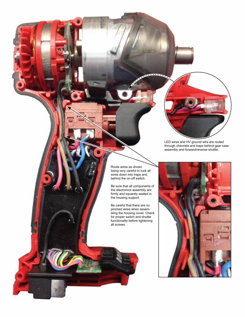
LED wires and HV ground wire are routed through channels and traps behind gear case assembly and forward/reverse shuttle.
Route wires as shownbeing very careful to tuck allwires down into traps and behind the on-off switch.
Be sure that all components of the electronics assembly are firmly and squarely seated in the housing support.
Be careful that there are no pinched wires when assem-bling the housing cover. Check for proper switch and shuttle functionality before tightening all screws.