Bulletin No. CUB7N-D Drawing No. LP0825 Tel +1 (717) 767 ...
8
1 1.64 (41.6) 0.87 (22.1) 1.10 (27.9) 2.00 (50.8) 2.17 (55) With Wires With Terminal Block l 0.35" (8.9 mm) HIGH LCD DIGITS, REFLECTIVE OR TRANSMISSIVE WITH YELLOW/GREEN OR RED BACKLIGHTING (6-26 VDC power supply required for version with LED backlighting) l INTERNAL LITHIUM BATTERY PROVIDES UP TO 7 YEARS OF TYPICAL UNINTERRUPTED OPERATION l COUNT SPEEDS UP TO 10KHZ l 9 PROGRAMMABLE TIME RANGES l CONTACT, LOGIC, OPEN COLLECTOR, OR HIGH VOLTAGE INPUTS l STANDARD WIRE CONNECTIONS OR OPTIONAL PLUG-IN TERMINAL BLOCK l NEMA 4X/IP65 SEALED FRONT BEZEL THAT FITS 1/32 DIN CUT-OUT DESCRIPTION The CUB7 series is an 8-digit lithium battery powered miniature counter or timer with large 0.35" (8.9 mm) high digits. It has an LCD read-out available in Positive Imagine Reflective, Negative Image Transmissive with yellow/green or red backlighting. The backlight versions require an external 6-26 VDC power supply. The CUB7 series is housed in a lightweight, high impact plastic case with a clear viewing window. The sealed front panel with silicon rubber keypad meets NEMA 4X/IP65 specification for wash-down and/or dusty environments, when properly installed with supplied panel gasket and mounting clip. Both counter and timer CUB7 models are available with a low voltage input (28 VDC max) or an isolated high voltage input (50-250 VDC/VAC). The low voltage input has DIP switch selections for SINKING or SOURCING along with a HIGH/LOW FREQUENCY selection (low frequency for contact inputs). Both units have front panel keypads that can be used to reset the display. The keypad can be enabled/disabled via a single DIP switch. The standard unit uses 22 gauge wires for external connections, an optional plug-in terminal block is available. SAFETY SUMMARY All safety related regulations, local codes and instructions that appear in the literature or on equipment must be observed to ensure personal safety and to prevent damage to either the instrument or equipment connected to it. If equipment is used in a manner not specified by the manufacturer, the protection provided by the equipment may be impaired. SPECIFICATIONS 1. DISPLAY: 8-digit LCD, 0.35" (8.90 mm) high digits 2. POWER: Non-replaceable internal 3.6 VDC lithium battery provides 7 years of typical continuous operation (high count speeds in SNK mode & extreme ambient temperatures will decrease battery life, use of SRC mode can extend battery life) OPTIONAL LED BACKLIGHT POWER: 6-26 VDC @ 25 mA max. Must use an NEC Class 2 or Limited Power Source (LPS) rated power supply. Note: External power shall incorporate disconnecting device (switch or circuit breaker) and provide Double/Reinforced isolation from MAINS supply. 3. LOW VOLTAGE INPUT: COUNTERS: CUB7CCS0, CUB7CCR0, CUB7CCG0 SNK mode (DIP switch 1 off, internal pull-up to battery) V IN High Min = 1.25 VDC; V IN Low Max = 0.45 VDC I IN Max = 8 µA; V IN Max = 3.6 VDC Count Speed: (count on negative edge) High freq mode (DIP switch 2 off): max 5 kHz @ 50% duty cycle Low freq mode (DIP switch 2 on): max 30 Hz @ 50% duty cycle Note: The three models listed above may be used for count inputs with 10-50 VAC signals when using a VCM10000 converter module. DIP switches must be set for SNK and Low frequency. SRC mode (DIP switch 1 on, internal 20 kW pull-down to common) V IN High Min = 1.25 VDC; V IN Low Max = 0.45 VDC I IN Max = 5 mA; V IN Max = 28 VDC Count Speed: (count on negative edge) High freq mode (DIP switch 2 off): max 10 kHz @ 50% duty cycle Low freq mode (DIP switch 2 on): max 50 Hz @ 50% duty cycle TIMERS: Models: CUB7TCS0, CUB7TCR0, CUB7TCG0 For these models, the unit will time when the CUB7 input is low. SNK mode (DIP switch 1 off, internal pull-up to battery) V IN High Min = 1.25 VDC; V IN Low Max = 0.45 VDC I IN Max = 8 µA; V IN Max = 3.6 VDC Note: The three models listed above may be used with 10-50 VAC MODEL CUB7 – MINIATURE ELECTRONIC 8 DIGIT COUNTER or TIMER DIMENSIONS In inches (mm) Note: Recommended minimum clearance (behind the panel) for mounting clip installation is 2.1" (53.4) H x 5.5" (140) W. Bulletin No. CUB7N-D Drawing No. LP0825 Released 09/12 Tel +1 (717) 767-6511 Fax +1 (717) 764-0839 www.redlion.net C US LISTED U L R 3RSD PROCESS CONTROL EQUIPMENT CAUTION: Risk of Danger. Read complete instructions prior to installation and operation of the unit. CAUTION: Risk of electric shock.
Transcript of Bulletin No. CUB7N-D Drawing No. LP0825 Tel +1 (717) 767 ...

1
1.64 (41.6)
0.87(22.1)
1.10(27.9)
2.00 (50.8) 2.17 (55)
With Wires With Terminal Block
l 0.35" (8.9 mm) HIGH LCD DIGITS, REFLECTIVE OR TRANSMISSIVE WITH YELLOW/GREEN OR RED BACKLIGHTING (6-26 VDC power supply required for version with LED backlighting)
l INTERNAL LITHIUM BATTERY PROVIDES UP TO 7 YEARS OF TYPICAL UNINTERRUPTED OPERATION
l COUNT SPEEDS UP TO 10KHZ
l 9 PROGRAMMABLE TIME RANGES
l CONTACT, LOGIC, OPEN COLLECTOR, OR HIGH VOLTAGE INPUTS
l STANDARD WIRE CONNECTIONS OR OPTIONAL PLUG-IN TERMINAL BLOCK
l NEMA 4X/IP65 SEALED FRONT BEZEL THAT FITS 1/32 DIN CUT-OUT
DESCRIPTIONThe CUB7 series is an 8-digit lithium battery powered miniature counter or
timer with large 0.35" (8.9 mm) high digits. It has an LCD read-out available in Positive Imagine Reflective, Negative Image Transmissive with yellow/green or red backlighting. The backlight versions require an external 6-26 VDC power supply. The CUB7 series is housed in a lightweight, high impact plastic case with a clear viewing window. The sealed front panel with silicon rubber keypad meets NEMA 4X/IP65 specification for wash-down and/or dusty environments, when properly installed with supplied panel gasket and mounting clip.
Both counter and timer CUB7 models are available with a low voltage input (28 VDC max) or an isolated high voltage input (50-250 VDC/VAC). The low voltage input has DIP switch selections for SINKING or SOURCING along with a HIGH/LOW FREQUENCY selection (low frequency for contact inputs). Both units have front panel keypads that can be used to reset the display. The keypad can be enabled/disabled via a single DIP switch. The standard unit uses 22 gauge wires for external connections, an optional plug-in terminal block is available.
SAFETY SUMMARYAll safety related regulations, local codes and instructions that appear in the
literature or on equipment must be observed to ensure personal safety and to prevent damage to either the instrument or equipment connected to it. If equipment is used in a manner not specified by the manufacturer, the protection provided by the equipment may be impaired.
SPECIFICATIONS1. DISPLAY: 8-digit LCD, 0.35" (8.90 mm) high digits2. POWER: Non-replaceable internal 3.6 VDC lithium battery provides 7 years
of typical continuous operation (high count speeds in SNK mode & extreme ambient temperatures will decrease battery life, use of SRC mode can extend battery life)OPTIONAL LED BACKLIGHT POWER: 6-26 VDC @ 25 mA max.
Must use an NEC Class 2 or Limited Power Source (LPS) rated power supply.Note: External power shall incorporate disconnecting device (switch or circuit
breaker) and provide Double/Reinforced isolation from MAINS supply.3. LOW VOLTAGE INPUT:
COUNTERS: CUB7CCS0, CUB7CCR0, CUB7CCG0SNK mode (DIP switch 1 off, internal pull-up to battery)
VIN High Min = 1.25 VDC; VIN Low Max = 0.45 VDCIIN Max = 8 µA; VIN Max = 3.6 VDCCount Speed: (count on negative edge)
High freq mode (DIP switch 2 off): max 5 kHz @ 50% duty cycleLow freq mode (DIP switch 2 on): max 30 Hz @ 50% duty cycle
Note: The three models listed above may be used for count inputs with 10-50 VAC signals when using a VCM10000 converter module. DIP switches must be set for SNK and Low frequency.
SRC mode (DIP switch 1 on, internal 20 kW pull-down to common)VIN High Min = 1.25 VDC; VIN Low Max = 0.45 VDCIIN Max = 5 mA; VIN Max = 28 VDCCount Speed: (count on negative edge)
High freq mode (DIP switch 2 off): max 10 kHz @ 50% duty cycleLow freq mode (DIP switch 2 on): max 50 Hz @ 50% duty cycle
TIMERS: Models: CUB7TCS0, CUB7TCR0, CUB7TCG0 For these models, the unit will time when the CUB7 input is low.SNK mode (DIP switch 1 off, internal pull-up to battery)
VIN High Min = 1.25 VDC; VIN Low Max = 0.45 VDCIIN Max = 8 µA; VIN Max = 3.6 VDCNote: The three models listed above may be used with 10-50 VAC
MODEL CUB7 – MINIATURE ELECTRONIC 8 DIGIT COUNTER or TIMER
DIMENSIONS In inches (mm) Note: Recommended minimum clearance (behind the panel) for mounting clip installation is 2.1" (53.4) H x 5.5" (140) W.
Bulletin No. CUB7N-D
Drawing No. LP0825
Released 09/12
Tel +1 (717) 767-6511
Fax +1 (717) 764-0839
www.redlion.net
C US LISTEDULR
3RSDPROCESS CONTROL EQUIPMENT
CAUTION: Risk of Danger.Read complete instructions prior to
installation and operation of the unit.
CAUTION: Risk of electric shock.
2
Ordering infOrmatiOn
Accessories Part NumbersTYPE DESCRIPTION PART NUMBER USED WITH
Plug-in Terminal Block
3 Position Terminal Block TB100003 CUB7CCS0, CUB7TCS0, CUB7TCS1
4 Position Terminal Block TB100004CUB7CCG0, CUB7TCG0, CUB7TCG1, CUB7CCR0, CUB7TCR0, CUB7TCR1, CUB7CVS0, CUB7TVS0
5 Position Terminal Block TB100005 CUB7CVG0, CUB7TVG0, CUB7CVR0, CUB7TVR0
Enclosure * CUB7 Enclosure ENC13000
Base Mount * CUB7 Base Mount BMK80000
See Wiring the Meter section to determine the terminal block needed.* Enclosure and base mount will NOT function with plug-in terminal block option.
CUB7 0
C - LOW VOLTAGE +28 VDC maxV - HIGH VOLTAGE 50-250 VAC/DC
S - REFLECTIVER - REDG - GREEN
C
signals when using a VCM10000 converter module.SRC mode (DIP switch 1 on, internal 20 kW pull-down to common)
VIN High Min = 1.25 VDC; VIN Low Max = 0.45 VDCIIN Max = 5 mA; VIN Max = 28 VDC
Models: CUB7TCS1, CUB7TCR1, CUB7TCG1 For these models, the unit will time when the CUB7 input is high.SNK mode (DIP switch 1 off - DO NOT USE) SRC mode (DIP switch 1 on, internal 20 kW pull-down to common)
VIN High Min = 1.25 VDC; VIN Low Max = 0.45 VDCIIN Max = 5 mA; VIN Max = 28 VDC
4. HIGH VOLTAGE INPUT: COUNTERS: CUB7CVS0, CUB7CVR0, and CUB7CVG0
The unit adds one count with voltage presentVIN Range = 50-250 VDC/VAC 50/60 Hz, 5 mA maxIsolation: 2500 VAC 1 min
TIMERS: CUB7TVS0, CUB7TVR0, and CUB7TVG0Unit will time with voltage presentVIN Range = 50-250 VDC/VAC 50/60 Hz, 5 mA maxIsolation: 2500 VAC 1 min
5. RESET INPUT: VIN Low Max = 1.5 VDC (internal pull-up to battery)IIN Max = 20 µA5 msec min (active low)
Note: Reset input is active low to clear display to zero6. TIMER ACCURACY:
CUB7TV: 0.03% +100 msec per RUN terminal activationCUB7TC low freq/snk setup: 0.03% +1 msec per RUN terminal activationCUB7TC high freq/snk setup: 0.03% -1 msec per RUN terminal activation
7. ENVIRONMENTAL CONDITIONS:Operating Temperature: 0 to 50 °CStorage Temperature: -30 to 80 °CVibration according to IEC 68-2-6: Operational 5 to 500 Hz, in X, Y, Z
direction for 1.5 hours, 5 g.Shock according to IEC 68-2-27: Operational 30 g, 11 msec in 3 directions.Operating and Storage Humidity: 85% max. (non-condensing)
8. CONNECTIONS: 22 gauge wire; wire length minimum 10"OPTIONAL TERMINAL BLOCKS: Wire clamping terminals
Wire Strip Length: 0.275" (7 mm)Wire Gage: 24-16 AWG copper wire
9. CONSTRUCTION: High impact plastic case with clear viewing window. The front panel meets NEMA 4X/IP65 requirements for outdoor use when properly installed. Installation Category II, Pollution Degree 2. Panel gasket and mounting clip are included.
10. CERTIFICATIONS AND COMPLIANCES:SAFETYUL Listed, File # E179259, UL508
Type 4X Outdoor Enclosure rating (Face only), UL50IEC 61010-1, EN 61010-1: Safety requirements for electrical equipment
for measurement, control, and laboratory use, Part 1.IP65 Enclosure rating (Face only), IEC 529
ELECTROMAGNETIC COMPATIBILITYEmissions and Immunity to EN 61326:2006: Electrical Equipment for
Measurement, Control and Laboratory use.Immunity to Industrial Locations:Electrostatic discharge EN 61000-4-2 Criterion A
4 kV contact discharge8 kV air discharge
Electromagnetic RF fields EN 61000-4-3 Criterion A10 V/m (80 MHz to 1 GHz)3 V/m (1.4 GHz to 2 GHz)1 V/m (2 GHz to 2.7 GHz)
Fast transients (burst) EN 61000-4-4 Criterion A2 kV power1 kV I/O signal
Surge EN 61000-4-5 Criterion Apower 1 kV L to L,
2 kV L to GRF conducted interference EN 61000-4-6 Criterion A
3 VrmsPower freq magnetic fields EN 61000-4-8 Criterion A
30 A/mAC power EN 61000-4-11
Voltage dip Criterion A0% during 1 cycle40% during 10/12 cycle70% during 25/30 cycle
Short interruptions Criterion B0% during 250/300 cycles
Emissions:Emissions EN 55011 Class BNotes:
1. Criterion A: Normal operation within specified limits.2. Criterion B: Temporary loss of performance from which the unit self-
recovers.Refer to the EMC Installation Guidelines section of the bulletin for
additional information.11. WEIGHT: 0.11 lbs. (0.05 Kg)
COUNTERS
CUB7 0
C - LOW VOLTAGE +28 VDC maxV - HIGH VOLTAGE 50-250 VAC/DC
S - REFLECTIVER - REDG - GREEN
T
0 - USE WITH LOW VOLTAGE TO TIME WHEN INPUT IS LOW USE WITH HIGH VOLTAGE TO TIME WHEN INPUT IS HIGH
1 - VALID ONLY WITH LOW VOLTAGE (C) USE WITH 28 VDC (SRC MODE) TO TIME WHEN INPUT IS HIGH
TIMERS

3
1.0 installing the meterINSTALLATION ENVIRONMENT
The unit should be installed in a location that does not exceed the maximum operating temperature and provides good air circulation. Placing the unit near devices that generate excessive heat should be avoided.
The bezel should be cleaned only with a soft cloth and neutral soap product. Do NOT use solvents.
Continuous exposure to direct sunlight may accelerate the aging process of the bezel. Do not use tools of any kind (screwdrivers, pens, pencils, etc.) to operate the keypad of the unit.
InstallationThe CUB7 series of products meets NEMA 4X/IP65 requirements for
outdoor use, when properly installed. The units are intended to be mounted into an enclosed panel. The viewing window and reset button are factory sealed for a washdown environment. A sponge rubber gasket and mounting clip are provided for installing the unit in the panel cut-out.
The following procedure assures proper installation:1. Cut panel opening to specified dimensions. Remove burrs and clean around
panel opening.2. Carefully remove and discard the center section of the gasket. Slide the panel
gasket over the rear of the unit to the back of the bezel. Insert the mounting screws onto both sides of mounting clip. The tip of the screw should NOT project from the hole in the mounting clip.
3. Install the CUB7 unit through the panel cut-out until the front bezel flange contacts the panel.
4. Slide the mounting clip over the rear of the unit until the clip is against the back of the panel. The mounting clip has latching features which engage into mating features on the CUB7 housing.
Note: It is necessary to hold the unit in place when sliding mounting clip into position.
5. Alternately tighten each screw to ensure uniform gasket pressure. Visually inspect the front panel gasket. The gasket should be compressed to about 75 to 80% of its original thickness. If not, gradually turn mounting screws to further compress gasket.
6. If gasket is not adequately compressed and the mounting screws can no longer be turned, loosen mounting screws, and check that mounting clip is latched as close as possible to the panel.
7. Repeat from step #5 for tightening mounting screws.
Latching Feature
Bezel
Gasket
MountingClip
MountingScrew
0.88
1.77
(22.2 )
(45 )+0.024-0.000
+0.6-0.0 +0.012
-0.000+0.3-0.0

4
4.0 resetting the displayThe display may be reset to zero via the front RST key, the remote reset input
or both.The front RST key must be enabled for front panel reset. DIP switch # 3 on
the low voltage input units or the single DIP switch on the high voltage input units. (See 2.0 Setting the DIP Switches for switch location)
The remote reset is activated via an external momentary contact closure between the reset input (blue wire) and the common (black wire). When the optional terminal blocks are used, see 5.0 Wiring The Meter, for the appropriate reset input terminal and the common terminal.
3.0 prOgramming the time rangeThe CUB7 Timer has 9 time ranges. To change ranges, enable the front
keypad with the DIP switch and press the SEL key. The currently programmed time range will be displayed (example 2222222.2 = time range 2). To change the range, press the RST key. The ranges will cycle from 0-8 and back to 0. To enter your time range, press the SEL key and the unit will retain the current time range and return back to normal.
DISPLAY DURING PROGRAMMING TIMER RANGE
00000.000 0.001 SEC111111.11 0.01 SEC2222222.2 0.1 SEC333333333 1 SEC4444444.4 0.1 MIN555555555 1 MIN666666.66 0.01 HR7777777.7 0.1 HR88888888 1 HR
SEL RST
85374216
2.0 setting the dip switches
Low voltage input units have 3 DIP switches that must be positioned appropriately prior to wiring.
High voltage input units have 1 DIP switch to enable or disable the front bezel keypad.
Rear of Unit
Bottom of Unit
Low Voltage Input Unit
ON
SR
CS
NK
KE
Y E
NK
EY
DIS
LO F
RE
QH
I FR
EQ
1 2 3
Rear of Unit
Bottom of Unit
High Voltage Input Unit
ON
KE
Y E
NK
EY
DIS
1
Note: Placing the KEY DISABLE/ENABLE DIP switch in the OFF position, disables all front panel keys.

5
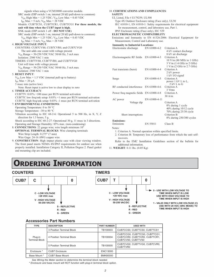
5.0 wiring the meterWIRING OVERVIEW
Electrical connections are made to the #22 AWG colored wires protruding from the rear of the unit. When using the optional terminal block, the #22 AWG colored wires are cut off and electrical connections are made via screwless type terminal block. All conductors should conform to the meter’s voltage and current ratings. All cabling and wire terminations should conform to appropriate standards of good installation, local codes and regulations. It is recommended that the backlight power supplied to the meter (DC or AC) be protected by a fuse or circuit breaker.
EMC INSTALLATION GUIDELINESAlthough this meter is designed with a high degree of immunity to Electro-
Magnetic Interference (EMI), proper installation and wiring methods must be followed to ensure compatibility in each application. The type of the electrical noise, source or coupling method into the meter may be different for various installations. The meter becomes more immune to EMI with fewer I/O connections. Cable length, routing, and shield termination are very important and can mean the difference between a successful or troublesome installation. Listed below are some EMC guidelines for successful installation in an industrial environment.1. The meter should be mounted in a metal enclosure, which is properly
connected to protective earth.2. Use shielded (screened) cables for all Signal and Control inputs. The shield
(screen) pigtail connection should be made as short as possible. The connection point for the shield depends somewhat upon the application. Listed below are the recommended methods of connecting the shield, in order of their effectiveness.a. Connect the shield only at the panel where the unit is mounted to earth
ground (protective earth).b. Connect the shield to earth ground at both ends of the cable, usually when
the noise source frequency is above 1 MHz.c. Connect the shield to common of the meter and leave the other end of the
shield unconnected and insulated from earth ground.
3. Never run Signal or Control cables in the same conduit or raceway with AC power lines, conductors feeding motors, solenoids, SCR controls, and heaters, etc. The cables should be ran in metal conduit that is properly grounded. This is especially useful in applications where cable runs are long and portable two-way radios are used in close proximity or if the installation is near a commercial radio transmitter.
4. Signal or Control cables within an enclosure should be routed as far as possible from contactors, control relays, transformers, and other noisy components.
5. In extremely high EMI environments, the use of external EMI suppression devices, such as ferrite suppression cores, is effective. Install them on Signal and Control cables as close to the unit as possible. Loop the cable through the core several times or use multiple cores on each cable for additional protection. Install line filters on the power input cable to the unit to suppress power line interference. Install them near the power entry point of the enclosure. The following EMI suppression devices (or equivalent) are recommended:
Ferrite Suppression Cores for signal and control cables:Fair-Rite # 0443167251 (RLC# FCOR0000)TDK # ZCAT3035-1330ASteward # 28B2029-0A0
Line Filters for input power cables:Schaffner # FN610-1/07 (RLC# LFIL0000)Schaffner # FN670-1.8/07Corcom # 1 VR3
Note: Reference manufacturer’s instructions when installing a line filter.6. Long cable runs are more susceptible to EMI pickup than short cable runs.
Therefore, keep cable runs as short as possible.7. Switching of inductive loads produces high EMI. Use of snubbers across
inductive loads suppresses EMI. Snubber: RLC# SNUB0000.
USING THE COLOR CODED WIRESThe low voltage input units will contain three or four color coded wires
depending on the backlight power requirements.The high voltage input units will contain (2) orange wires and an additional
two or three wires depending on the backlight power requirements.The tables define the function of each colored wire.
LOW VOLTAGE INPUTWire Colors
WHITE BLUE BLACK RED
Low Voltage Input Reset Common +Backlight Power
HIGH VOLTAGE INPUTWire Colors
ORANGE ORANGE BLUE BLACK RED
High Voltage Input
High Voltage Input Reset Common +Backlight
Power
TERMINAL BLOCK OPTION
1 2 3 4 51 2 3 1 2 3 4CONNECTIONS: Wire clamping terminals
Wire Strip Length: 0.275" (7 mm)Wire Gage: 24-16 AWG copper wire

6
SR
CLO
FR
EQ
KE
Y E
NK
EY
DIS
HI F
RE
Q
21
SN
K
ON
*3
LV IN
PU
T
1
RE
SE
T
+BA
CK
LIG
HT
PO
WE
R
CO
MM
ON
32 4OptionalBacklightPower
+
−
SR
CLO
FR
EQ
KE
Y E
NK
EY
DIS
HI F
RE
Q
21
SN
K
ON
*3
1 32 4OptionalBacklightPower
+V+
−
LV IN
PU
T
RE
SE
T
+BA
CK
LIG
HT
PO
WE
R
CO
MM
ON
SR
CLO
FR
EQ
KE
Y E
NK
EY
DIS
HI F
RE
Q
21
SN
K
ON
*3
1 32 4OptionalBacklightPower
+
−
LV IN
PU
T
RE
SE
T
+BA
CK
LIG
HT
PO
WE
R
CO
MM
ON
KE
Y E
NLO
FR
EQ
SR
CS
NK
HI F
RE
QK
EY
DIS
1
ON
32*
1 32 4OptionalBacklightPower
+
−
LV IN
PU
T
RE
SE
T
+BA
CK
LIG
HT
PO
WE
R
CO
MM
ON
SR
CLO
FR
EQ
KE
Y E
NK
EY
DIS
HI F
RE
Q
21
SN
K
ON
*3
1 32 4
LV IN
PU
T
RE
SE
T
+BA
CK
LIG
HT
PO
WE
R
CO
MM
ON
OptionalBacklightPower
+V+
−
KE
Y E
NK
EY
DIS
ON
*3
HV
INP
UT
2
RE
SE
T
+BA
CK
LIG
HT
PO
WE
R
CO
MM
ON
43 5
HV
INP
UT
1OptionalBacklightPower
50-250VDC/VAC +
−
Current Sourcing Output Logic OutputCurrent Sinking Output
Switch/Contact Sourcing Output High Voltage Switch/Contact Sinking Output
Switch position is application dependent. Shaded area for high voltage applications.
SideLatches
USING THE OPTIONAL TERMINAL BLOCK1. Remove the rear cover. Refer to Figure 1. A small slotted screwdriver is
required to release the side latches. Insert the screwdriver tip between the rear cover and the side of the unit. Leverage the screwdriver away from the case to unlatch the side latch and slightly lift the rear cover. Pinch the corners to hold the rear cover in place. Remove the screwdriver and repeat the same procedure on the other side of the rear cover. When both side latches are released, slide the rear cover from the unit and the wires.
2. For safety concerns, the wires should be cut off completely flush with the PC board to prevent a short.
3. Break out the break away tab(s) as required. Remove the left tab only for 3 position terminal block or both tabs for 4 and 5 position terminal blocks.
4. Reinstall the rear cover into CUB7 unit.5. Mount the CUB7 into the panel (refer to 1.0 Installing The Meter)6. Push the keyed terminal block onto the exposed PC board. The left most
terminal, next to the DIP switch(s) is terminal #1.
Note: Wire sizes 16-24 AWG may be used with 0.25" length exposed. The screwless type terminal block requires a small slotted screwdriver engaged in the upper slot to open the wire clamp in the lower larger slot. Removing the screwdriver will lock the wire clamp unto the wire.
Wires must be cut off completely flush with PC board.
DIP Switch(s)
Cut Wires Internally(If using Optional
Terminal Block) Side Latches
Break-out Tab or Tabs(If using Optional
Terminal Block)
Rear Cover
Mounting Clip
OptionalTerminal Block
Open & LockWire Clamp
Terminal #1
Figure 1

7
This page intentionally left blank.

8
LIMITED WARRANTYThe Company warrants the products it manufactures against defects in materials and
workmanship for a period limited to two years from the date of shipment, provided the products have been stored, handled, installed, and used under proper conditions. The Company’s liability under this limited warranty shall extend only to the repair or replacement of a defective product, at The Company’s option. The Company disclaims all liability for any affirmation, promise or representation with respect to the products.
The customer agrees to hold Red Lion Controls harmless from, defend, and indemnify RLC against damages, claims, and expenses arising out of subsequent sales of RLC products or products containing components manufactured by RLC and based upon personal injuries, deaths, property damage, lost profits, and other matters which Buyer, its employees, or sub-contractors are or may be to any extent liable, including without limitation penalties imposed by the Consumer Product Safety Act (P.L. 92-573) and liability imposed upon any person pursuant to the Magnuson-Moss Warranty Act (P.L. 93-637), as now in effect or as amended hereafter.
No warranties expressed or implied are created with respect to The Company’s products except those expressly contained herein. The Customer acknowledges the disclaimers and limitations contained herein and relies on no other warranties or affirmations.
Red Lion ControlsHeadquarters20 Willow Springs CircleYork PA 17406Tel +1 (717) 767-6511Fax +1 (717) 764-0839
Red Lion ControlsChina
Unit 101, XinAn PlazaBuilding 13, No.99 Tianzhou Road
ShangHai, P.R. China 200223Tel +86 21 6113-3688Fax +86 21 6113-3683
Red Lion ControlsEurope
Printerweg 10NL - 3821 AD AmersfoortTel +31 (0) 334 723 225Fax +31 (0) 334 893 793
Red Lion ControlsIndia
201-B, 2nd Floor, Park CentraOpp 32 Mile Stone, Sector-30
Gurgaon-122002 Haryana, IndiaTel +91 984 487 0503