Bulletin B-207G Bell & Gossett - pumpfundamentals.com€¦ · Consult your local Bell & Gossett...
12
• For hydronic heating and cooling systems, industrial, pressure boosting and general pumping applications • High efficiency, low operating costs • Easy maintenance • Seal options Series 1510 Centrifugal Pumps – Technical Bulletin Bulletin B-207G Bell & Gossett Equipment Selection Program Bell & Gossett Part of the
Transcript of Bulletin B-207G Bell & Gossett - pumpfundamentals.com€¦ · Consult your local Bell & Gossett...
• For hydronic heating and cooling systems, industrial,pressure boosting and general pumping applications
• High efficiency, low operating costs
• Easy maintenance
• Seal options
Series 1510Centrifugal Pumps –Technical Bulletin
Bulletin B-207G
Bell & Gossett
Equipment Selection Program
Bell & GossettPart of the
Pressure = Head (Feet) x Specific Gravity(PSI) 2.31
Head = Pressure (PSI) x 2.31(Feet) Specific Gravity
Vacuum = Dynamic Suction Lift (Feet) x .883 (Inches of Mercury) x Specific Gravity
Horsepower = GPM x Head (Feet) x Specific Gravity(Brake) 3960 x Pump Efficiency
Horsepower = GPM x Head (Feet) x Specific Gravity(Water) 3960
Efficiency = Horsepower (Water) x 100 Per Cent(Pump) Horsepower (Brake)
NPSH = Positive Factors – Negative Factors(Available)
GPM Capacity Ft. Head BHP
ImpellerDiameterChange
SpeedChange
2
Table of ContentsUseful Pump Formulas . . . . . . . . . . . . . . . . . . . . . . . . . . . . . . . . . . . . . . . . . . 2
Standard Features . . . . . . . . . . . . . . . . . . . . . . . . . . . . . . . . . . . . . . . . . . . . . . 3
Technical Data . . . . . . . . . . . . . . . . . . . . . . . . . . . . . . . . . . . . . . . . . . . . . . . . 4
Materials of Construction . . . . . . . . . . . . . . . . . . . . . . . . . . . . . . . . . . . . . . . . 5
Selection Charts . . . . . . . . . . . . . . . . . . . . . . . . . . . . . . . . . . . . . . . . . . . . . . . 6
Performance Curves . . . . . . . . . . . . . . . . . . . . . . . . . . . . . . . . . . . . . . . . . . . . 7
Centrifugal Pump Dimensions . . . . . . . . . . . . . . . . . . . . . . . . . . . . . . . . . . . . . 8-9
The B&G End Suction Pump System . . . . . . . . . . . . . . . . . . . . . . . . . . . . . . . . 10
Typical Specifications . . . . . . . . . . . . . . . . . . . . . . . . . . . . . . . . . . . . . . . . . . . 11
Useful Pump Formulas
Affinity Laws: Effect of change of speed or impeller diameter on centrifugal pumps.
Where Q = GPM, H = Head, P = BHP, D = Impeller Dia., RPM = Pump Speed
Q2 = Q1D2
D1
Q2 = Q1RPM2
RPM1H2 = ( )2
H1RPM2
RPM1P2 = ( )3
P1RPM2
RPM1
P2 = ( )3
P1D2
D1H2 = ( )2
H1D2
D1
3
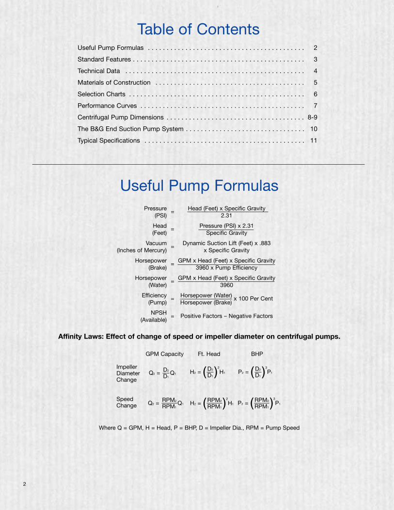
Take away these seven standard features and you’ll have a pump like everyone else’s.
TRUE BACK PULLOUTA B&G standard in design and construction. Ease in service isassured, while piping and motor remain undisturbed. Extendeddelays for repairs are virtually eliminated.
INTERNALLY SELF-FLUSHING MECHANICAL SEALThis design is way ahead of its time. This unique seal design isproven in many years of service. It requires no special externalflushing provisions, since the design provides for constantefficient flushing action internally.
This standard feature ensures maximum seal face lubrication,heat dissipation and debris removal without vulnerable, externalflush tubing. The internal flushing action passes two and a half tothree times the flow over the seal faces — compared to a fewGPM for conventional, stuffing-box designed pumps.
SOLID-FOOT MOUNTED VOLUTEAll Series 1510 pumps are provided as standard with an integral-ly cast volute foot located directly beneath the pump volute. Thisintegrally cast foot ensures that the alignment between the voluteand motor assembly is maintained. Without solid supportbeneath the volute, the piping weight alone will cause distortionwhich can lead to premature failure of the bearings, shaft andmechanical seal. This feature is equally important on hot waterapplications. The Series 1510 volute foot provides a solidfoundation and eliminates the deflections which would otherwiseexist within an unsupported overhung volute during the normalthermal expansion of the system piping against the volute.
HEAVY DUTY, RUGGED BASEPLATEThe Bell & Gossett fabricated heavy duty baseplate is supplied asstandard on every Series 1510 pump. Unlike rolled steel and “C”channel baseplates, the Series 1510 baseplate provides a heavyduty saddle assembly, full seam welds, closed baseplate endsand an open top to provide ease of access for proper equipmentgrouting.
COMPUTER CONTROLLEDIMPELLER BALANCING1510 impellers are balanced to HI/ANSI 1.1-1.5-1994 section1.4.6.1.3.1, balance grade G6.3 standards. This method of com-puter balancing Impellers provides for quiet, efficient, vibrationfree performance. Diameters are computer selected at the factoryto furnish assurance that your capacity requirements will be met.
CENTER DROP-OUT SPACER COUPLINGUnlike conventional jaw type or rigid style couplings, a centerdrop-out spacer coupling allows removal of the bearing frameand rotating element without disturbing the pump end pipe align-ment or motor electrical connections.
ANSI/OSHA-COMPLIANT COUPLING GUARDThe coupler guard complies with ANSI B15.1, Section 8 andOSHA 1910.219. The guard offers increased protection againstpotential injuries and is standard on all 1510 pumps. The guardsinclude slotted viewing windows for easy inspection.
4
Technical Data
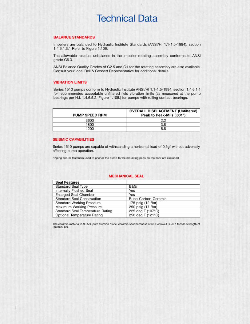
BALANCE STANDARDS
Impellers are balanced to Hydraulic Institute Standards (ANSI/HI 1.1-1.5-1994), section1.4.6.1.3.1 Refer to Figure 1.106.
The allowable residual unbalance in the impeller rotating assembly conforms to ANSIgrade G6.3.
ANSI Balance Quality Grades of G2.5 and G1 for the rotating assembly are also available.Consult your local Bell & Gossett Representative for additional details.
VIBRATION LIMITS
Series 1510 pumps conform to Hydraulic Institute ANSI/HI 1.1-1.5-1994, section 1.4.6.1.1for recommended acceptable unfiltered field vibration limits (as measured at the pumpbearings per H.I. 1.4.6.5.2, Figure 1.108.) for pumps with rolling contact bearings.
OVERALL DISPLACEMENT (Unfiltered)PUMP SPEED RPM Peak to Peak-Mils (.001")
3600 2.21800 3.81200 5.8
SEISMIC CAPABILITIES
Series 1510 pumps are capable of withstanding a horizontal load of 0.5g* without adverselyaffecting pump operation.
*Piping and/or fasteners used to anchor the pump to the mounting pads on the floor are excluded.
MECHANICAL SEAL
The ceramic material is 99.5% pure alumina oxide, ceramic seat hardness of 68 Rockwell C, or a tensile strength of300,000 psi.
Seal FeaturesStandard Seal Type B&GInternally Flushed Seal YesEnlarged Seal Chamber YesStandard Seal Construction Buna-Carbon-CeramicStandard Working Pressure 175 psig (12 Bar)Maximum Working Pressure 250 psig (17 Bar)Standard Seal Temperature Rating 225 deg F (107°C)Optional Temperature Rating 250 deg F (121°C)
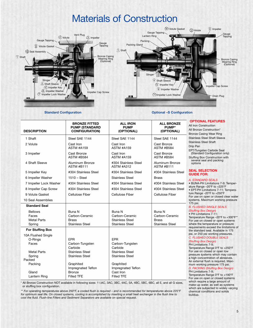
BRONZE FITTED ALL IRON ALL BRONZEPUMP (STANDARD PUMP PUMP*
DESCRIPTION CONFIGURATION) (OPTIONAL) (OPTIONAL)
11 Shaft Steel SAE 1144 Steel SAE 1144 Steel SAE 1144
12 Volute Cast Iron Cast Iron Cast BronzeASTM #A159 ASTM #A159 ASTM #B584
13 Impeller Cast Bronze Cast Iron Cast BronzeASTM #B584 ASTM #A159 ASTM #B584
14 Shaft Sleeve Aluminum Bronze #304 Stainless Steel Aluminum BronzeASTM #B111 ASTM #A312 ASTM #B111
15 Impeller Key #304 Stainless Steel #304 Stainless Steel #304 Stainless Steel
16 Impeller Washer 1510 – Steel Stainless Steel Brass
17 Impeller Lock Washer #304 Stainless Steel #304 Stainless Steel #304 Stainless Steel
18 Impeller Cap Screw #304 Stainless Steel #304 Stainless Steel #304 Stainless Steel
19 Volute Gasket Cellulose Fiber Cellulose Fiber Cellulose Fiber
10 Seal Assemblies
Standard Seal
Bellows Buna N Buna N Buna NFaces Carbon-Ceramic Carbon-Ceramic Carbon-CeramicMetal Parts Brass Stainless Steel BrassSpring Stainless Steel Stainless Steel Stainless Steel
For Stuffing Box
10A Flushed SingleO-Rings EPR EPRFaces Carbon-Tungsten Carbon-Tungsten
Carbide CarbideMetal Parts Stainless Steel Stainless SteelSpring Stainless Steel Stainless Steel
PackedPacking Graphited Graphited
Impregnated Teflon Impregnated TeflonGland Bronze Cast IronLantern Ring Filled TFE Filled TFE
5
OPTIONAL FEATURESAll Iron ConstructionAll Bronze Construction*Bronze Casing Wear RingStainless Steel Shaft SleeveStainless Steel ShaftDrip PanEPT/Tungsten Carbide Seal
(Standard Configuration only)Stuffing Box Construction with
several seal and packingoptions
SEAL SELECTION GUIDE FOR:
A. STANDARD SEALS• BUNA-PH Limitations 7-9; Temper-ature Range –20°F to +225°F • EPT-PH Limitations 7-11; Tempera-ture Range –20°F to +250°FFor use on open or closed clear watersystems. Maximum working pressure175 psi.B. FLUSHED SINGLE SEALS(Stuffing Box Design)• PH Limitations 7-11;Temperature Range –20°F to +300°F**For use on closed or open systemswhere the temperature or pressurerequirements exceed the limitations ofthe standard seal. Available in 175psi, or 250 psi working pressures.C. FLUSHED DOUBLE SEALS(Stuffing Box Design)PH Limitations 7-9; Temperature Range 0°F to +250°FFor use on closed or open low pressure systems which may containa high concentration of abrasives. An external flush is required. Maxi-mum working pressure 175 psi.D. PACKING (Stuffing Box Design)PH Limitations 7-9; Temperature Range 0°F to +190°FFor use on open or closed systemswhich require a large amount ofmake-up water, as well as systemswhich are subjected to widely varyingchemical conditions and solidsbuildup.
* All Bronze Construction NOT available in following sizes: 11/2AC, 3AC, 3BC, 4AC, 5A, 4BC, 5BC, 6BC, all E, and all G sizes,or stuffing box configuration.
Materials of Construction
10
ä
Vent PlugVolute
Gauge Tapping
Volute Gasket
Seal Assembly
Shaft
Impeller
GaugeTapping
Bronze CasingWearing Ring
(Optional)
Impeller Cap Screw
Slinger
Shaft SleeveImpeller Key
Impeller WasherImpeller Lock Washer
4
56
7
1
9
2 3
ä
ä
ä
ä
ä
ä
ä
ä
ä
äää
ä
ä
ä
VoluteGauge Tapping
Volute Gasket
Shaft
Impeller
GaugeTapping
Bronze CasingWearing Ring
(Optional)
Impeller Cap Screw
Drain Plug
Slinger
Shaft Sleeve
Impeller Key
Impeller Washer
Impeller Lock Washer
4
5
6
7
1
92 3
ä
ä
ä
äLantern Ring
Packing
Packing Gland
äää
ä
ä
ä
ä
ä
ää
ä
ä
ä ä
Standard Configuration Optional –S Configuration
** For operating temperatures above 250°F, a cooled flush is required – and is recommended for temperatures above 225°F for optimum seal life. On closed systems, cooling is accomplished by inserting a small heat exchanger in the flush line to cool the fluid. Flush-line Filters and Sediment Separators are available on special request.
6
Selection Charts
10 20 30 40 50 60 70 80 90 100200
300400
500600
700800
9001000
20003000
40005000
10 20 30 40 50 60 70 80 90 100200
300400
500600
700800
9001000
20003000
40005000
5
10
20
30
40
50
60708090
100
200
300
400
500
TO
TAL
HE
AD
, ft.
of
wat
er
CAPACITY, gpm
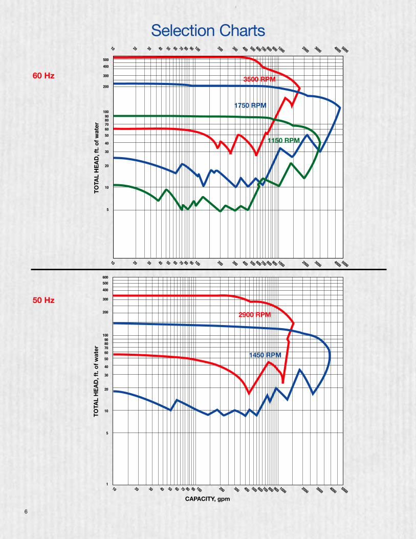
3500 RPM
1750 RPM
1150 RPM
10 20 30 40 50 60 70 80 90 100200
300400
500600
700800
9001000
20003000
40005000
CAPACITY, gpm
5
1
10
20
30
40
50
60708090
100
200
300
400
500
600
TO
TAL
HE
AD
, ft.
of
wat
er
2900 RPM
1450 RPM
60 Hz
50 Hz
560
520
480
440
400
360
320
280
240
200
160
120
80
40
CAPACITY IN U.S. GALLONS PER MINUTE
TOTA
L HE
AD, F
EET
050 100150
200250
300350
400450
5001000
15002000
2500
7
220
200
180
160
140
120
100
80
60
40
20
CAPACITY IN U.S. GALLONS PER MINUTE
0
20 40 60 80 100
120140160180200
400
600
800
100012001400160018002000
4000
5000
TOTA
L HE
AD, F
EET
2G
3G
4GB5G 6G
8G6E
6BC5BC4BC3BC
4AC3AC2AC
2BC
2E 3E 4E
5A
5E
112 BC
212 BB
114 BC
114 AC 11
2 AC21
2 AB
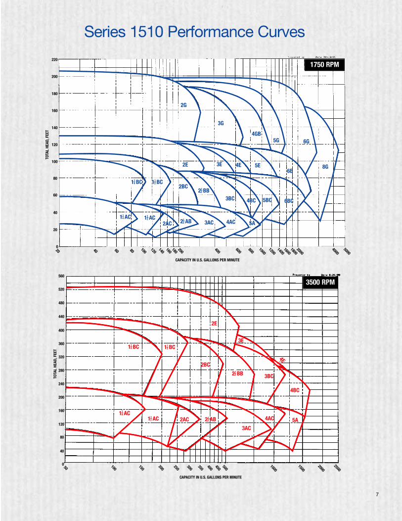
1750 RPM
Series 1510 Performance Curves
3E
2BC
2E
2AC
3BC
4BC
4E
5A4AC
3AC
114 BC
114 AC
112 BC
212 BB
212 AB11
2 AC
3500 RPM
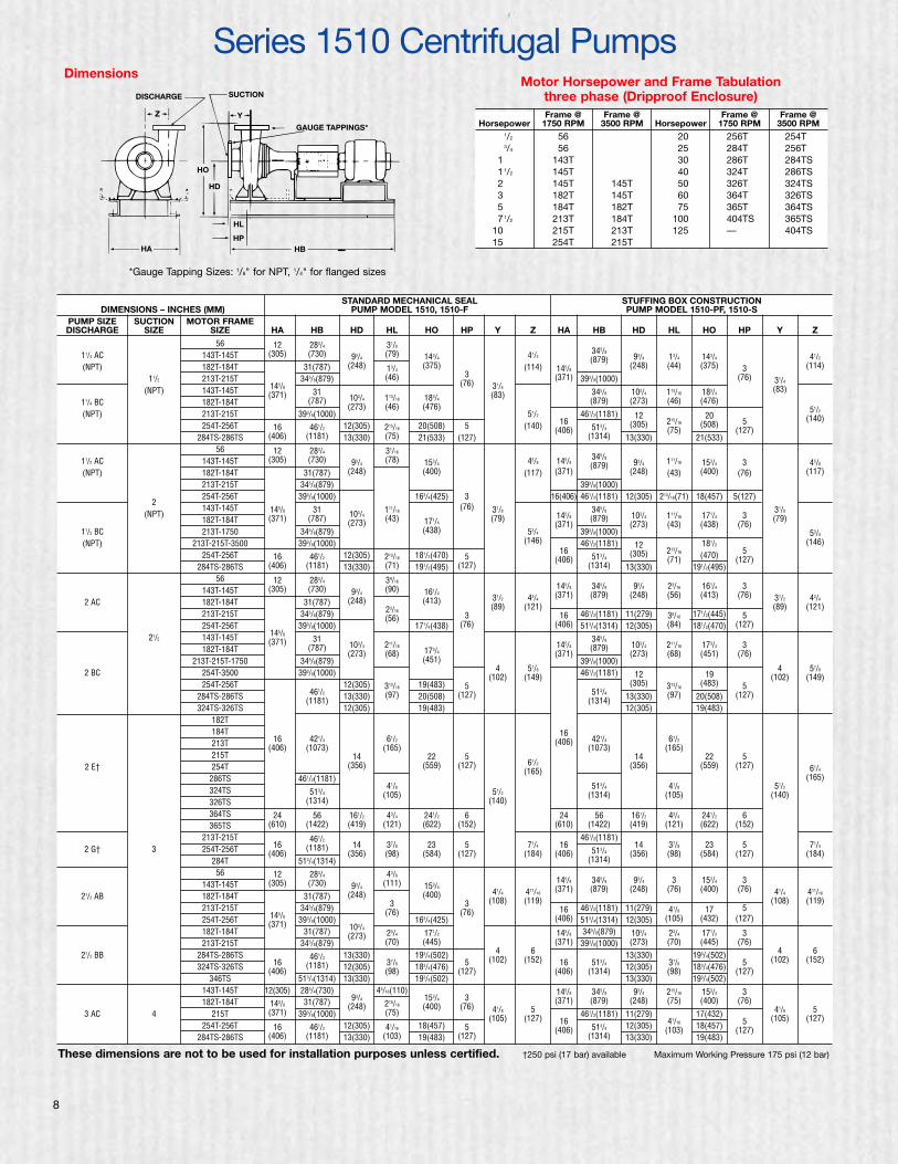
STANDARD MECHANICAL SEAL STUFFING BOX CONSTRUCTIONDIMENSIONS – INCHES (MM) PUMP MODEL 1510, 1510-F PUMP MODEL 1510-PF, 1510-S
PUMP SIZE SUCTION MOTOR FRAMEDISCHARGE SIZE SIZE HA HB HD HL HO HP Y Z HA HB HD HL HO HP Y Z
56 12 283/4 31/8
11/4 AC 143T-145T (305) (730) 93/4(79) 143/4 41/2
345/893/4 13/4 143/4 41/2
(NPT) 182T-184T 31(787) (248) 13/4(375) (114) 145/8
(879)(248) (44) (375) 3 (114)
11/2 213T-215T 345/8(879) (46) 3 (371) 393/8(1000) (76) 31/4
(NPT) 143T-145T 145/831
(76) 31/4345/8 103/4 113/16 183/4
(83)
11/4 BC 182T-184T(371)
(787) 103/4 113/16 183/4(83)
(879) (273) (46) (476)
(NPT) 213T-215T 393/8(1000)(273) (46) (476)
51/2 461/2(1181) 12 2051/2
254T-256T 16 461/2 12(305) 215/16 20(508) 5 (140) 16513/4
(305) 215/16 (508) 5 (140)
284TS-286TS (406) (1181) 13(330) (75) 21(533) (127)(406)
(1314) 13(330)(75)
21(533)(127)
56 12 283/4 31/16
11/2 AC 143T-145T (305) (730) 93/4(78) 153/4 45/8 145/8
345/893/4 111/16 153/4 3 45/8
(NPT) 182T-184T 31(787) (248) (400) (117) (371)(879)
(248) (43) (400) (76) (117)
213T-215T 345/8(879) 393/8(1000)254T-256T 393/8(1000) 163/4(425) 3 16(406) 461/2(1181) 12(305) 213/16(71) 18(457) 5(127)
2143T-145T 145/8 31 111/16
(76) 31/8 345/8 31/8(NPT)182T-184T (371) (787) 103/4 (43) 171/4
(79) 145/8 (879) 103/4 111/16 171/4 3 (79)
11/2 BC 213T-1750 345/8(879)(273)
(438) 53/4
(371)393/8(1000)
(273) (43) (438) (76)53/4
(NPT) 213T-215T-3500 393/8(1000) (146) 461/2(1181) 12 181/2 (146)
254T-256T 16 461/2 12(305) 213/16 181/2(470) 516
513/4(305) 213/16 (470) 5
284TS-286TS (406) (1181) 13(330) (71) 191/2(495) (127)(406)
(1314) 13(330)(71)
191/2(495)(127)
56 12 283/4 39/16145/8 345/8 93/4 23/16 161/4 3143T-145T (305) (730) 93/4
(90) 161/4 (371) (879) (248) (56) (413) (76)2 AC 182T-184T 31(787) (248) (413) 31/2 43/4 31/2 43/4
213T-215T 345/8(879) 23/163
(89) (121)16 461/2(1181) 11(279) 35/16 171/2(445) 5
(89) (121)
254T-256T 393/8(1000)(56)
171/4(438) (76) (406) 513/4(1314) 12(305) (84) 181/2(470) (127)
21/2 143T-145T 145/831 345/8
182T-184T(371)
(787) 103/4 211/16173/4
145/8 (879) 103/4 211/16 173/4 3
213T-215T-1750 345/8(879)(273) (68)
(451)(371)
393/8(1000)(273) (68) (451) (76)
2 BC 254T-3500 393/8(1000) 4 57/8 461/2(1181) 12 194 57/8
254T-256T 12(305) 313/16 19(483) 5(102) (149)
(305) 313/16(483) 5
(102) (149)
284TS-286TS 461/2 13(330) (97) 20(508) (127) 513/4 13(330) (97) 20(508) (127)
324TS-326TS(1181)
12(305) 19(483)(1314)
12(305) 19(483)182T184T 16213T 16 421/4 61/2 (406) 421/4 61/2
215T(406) (1073)
14(165)
22 561/2
(1073)14
(165)22 5
2 E† 254T (356) (559) (127)(165)
(356) (559) (127) 61/4
286TS 461/2(1181) (165)
324TS 513/441/8
51/2513/4 41/8 51/2
326TS (1314)(105)
(140)(1314) (105) (140)
364TS 24 56 161/2 43/4 241/2 6 24 56 161/2 43/4 241/2 6365TS (610) (1422) (419) (121) (622) (152) (610) (1422) (419) (121) (622) (152)
213T-215T 461/2 461/2(1181)2 G† 3 254T-256T 16 (1181) 14 37/8 23 5 71/4 16
513/414 37/8 23 5 71/4
284T(406)
513/4(1314)(356) (98) (584) (127) (184) (406)
(1314)(356) (98) (584) (127) (184)
56 12 283/4 43/8
143T-145T (305) (730) 93/4(111) 153/4
145/8 345/8 93/4 3 153/4 3
21/2 AB 182T-184T 31(787) (248) (400) 41/4 411/16(371) (879) (248) (76) (400) (76) 41/4 411/16
213T-215T 345/8(879) 3 3 (108) (119)16 461/2(1181) 11(279) 41/8 17 5
(108) (119)
254T-256T 145/8 393/8(1000)(76)
163/4(425)(76)
(406) 513/4(1314) 12(305) (105) (432) (127)
182T-184T(371)
31(787) 103/423/4 171/2 145/8 345/8(879) 103/4 23/4 171/2 3
213T-215T 345/8(879)(273)
(70) (445) (371) 393/8(1000) (273) (70) (445) (76)
21/2 BB 284TS-286TS 461/2 13(330) 193/4(502) 4 6 13(330) 193/4(502) 4 6
324TS-326TS 16 (1181) 12(305) 37/8 183/4(476) 5 (102) (152) 16 513/4 12(305) 37/8 183/4(476) 5 (102) (152)
346TS(406)
513/4(1314) 13(330)(98)
193/4(502)(127) (406) (1314)
13(330)(98)
193/4(502)(127)
143T-145T 12(305) 283/4(730) 45/16(110) 145/8 345/8 93/4 215/16 153/4 3182T-184T 145/8 31(787) 93/4
215/16153/4 3 (371) (879) (248) (75) (400) (76)
3 AC 4 215T (371) 393/8(1000)(248)
(75)(400) (76) 41/8 5 461/2(1181) 11(279) 17(432) 41/8 5
254T-256T 16 461/2 12(305) 41/16 18(457) 5(105) (127) 16
513/4 12(305) 41/16 18(457) 5 (105) (127)
284TS-286TS (406) (1181) 13(330) (103) 19(483) (127)(406)
(1314) 13(330)(103)
19(483)(127)
Series 1510 Centrifugal Pumps
Frame @ Frame @ Frame @ Frame @Horsepower 1750 RPM 3500 RPM Horsepower 1750 RPM 3500 RPM
.1/2 56 20 256T 254T
.3/4 56 25 284T 256T1. 143T 30 286T 284TS1.1/2 145T 40 324T 286TS2. 145T 145T 50 326T 324TS3. 182T 145T 60 364T 326TS5. 184T 182T 75 365T 364TS7.1/2 213T 184T 100 404TS 365TS
10. 215T 213T 125 — 404TS15. 254T 215T
DISCHARGE
Z
HA
HD
HL
HP
HO
Y
SUCTION
GAUGE TAPPINGS*
HB
DimensionsMotor Horsepower and Frame Tabulation
three phase (Dripproof Enclosure)
These dimensions are not to be used for installation purposes unless certified. †250 psi (17 bar) available Maximum Working Pressure 175 psi (12 bar)
*Gauge Tapping Sizes: 1/8" for NPT, 1/4" for flanged sizes
8

9
STANDARD MECHANICAL SEAL STUFFING BOX CONSTRUCTIONDIMENSIONS – INCHES (MM) PUMP MODEL 1510, 1510-F PUMP MODEL 1510-PF, 1510-S
PUMP SIZE SUCTION MOTOR FRAMEDISCHARGE SIZE SIZE HA HB HD HL HO HP Y Z HA HB HD HL HO HP Y Z
182T-184T 31(787) 145/8 345/8(879) 103/4 311/16 181/4 3
3 BC213T-215T 145/8 345/8(870) 103/4 311/16 181/4 3 (371) 393/8(1000) (273) (94) (464) (76)
254T(371)
393/8(1000)(273) (94) (464) (76) 43/4 61/8 461/2(1181) 12(305) 191/2(495) 43/4 61/8
284TS-286TS 461/2 13(330) 413/16 201/2(521)(121) (156) 16
513/4 13(330) 413/16 201/2(521) 5 (121) (156)
324TS-326TS (1181) 12(305) (122) 191/2(495)(406)
(1314) 12(305)(122)
191/2(495)(127)
184T213T-215T 16 421/4 611/16 5 421/4 611/16
3 E†254T
(406) (1073) 14 (170) 231/2(127) 16 (1073) 14 (170) 231/2 5
4256T 461/2(1181)
(356)45/16
(597) 51/2 73/8(406)
513/4
(356)45/16
(597) (127) 51/2 73/8
326TS 513/4(1314) (110)(140) (187)
(1314) (110)(140) (187)
364TS-365TS 24 56 161/2 415/16 26 6 24 56 161/2 415/16 26 6404TS (610) (1422) (419) (125) (660) (152) (610) (1422) (419) (125) (660) (152)
213T-215T 461/2 461/2(1181)
3 G†254T-256T 16 (1181) 14 41/8 231/2 5 55/8 8 16 14 41/8 231/2 5 55/8 8284T-286T (406) 513/4
(356) (105) (597) (127) (143) (203) (406) 513/4 (356) (105) (597) (127) (143) (203)
324T (1314)(1314)
145T 31 145/8 345/8
182T-184T 145/8(787) 103/4 45/16 181/4 3 (371) (879) 103/4 45/16 181/4 3
213T (371) 345/8(870) (273) (110) (464) (76) 393/8(1000)(273) (110) (464) (76)
4 AC† 215T 393/8(1000) 415/16 53/4 461/2(1181) 12 191/2415/16 53/4
254T-256T 12(305) 191/2(495)(125) (146)
(305) 57/16(495)
(125) (146)
284TS-286TS 16 461/2 13(330) 57/16 201/2(521) 516
513/4 13(330) (138) 201/2(521)324TS-326TS
(406) (1181)12(305)
(138)191/2(495)
(127)(406)
(1314)12(305) 191/2(495) 5
213T-215T 145/8 345/8(870) 123/4 4 203/4 3 461/2(1181)(127)
254T (371) 393/8(1000) (324) (102) (527) (76) 513/414 51/8 22 5 7
256T 461/2(1314)
(356) (130) (559) (127) (178)
4 BC 286TS 16 (1181) 14 51/8 22 5 5 7
324TS-326TS(406)
513/4(1314)(356) (130) (559) (127) (127) (178)
5 364TS-365TS 24 56 161/2 53/4 241/2 6404TS (610) (1422) (419) (146) (622) (152)
213T-215T 421/4 611/16 421/4 611/16
254T (1073) (170) (1073) (170)
256T 16 461/2(1181) 14 233/4 5 16 14 233/4 5
4 E† 284T-286T(406)
513/4
(356) 45/16(603) (127) 59/16 71/4
(406) 513/4(356) 45/16
(603) (127) 59/16 71/4
324TS-326TS (1314)(110) (141) (184) (1314) (110) (141) (184)
364TS-365TS 24 56 161/2 415/16 261/4 6 24 56 161/2 415/16 261/4 6404TS (610) (1422) (419) (125) (667) (152) (610) (1422) (419) (125) (667) (152)
213T-215T 461/2 461/2(1181)
4 GB254T-256T 16 (1181) 15 53/8 25 5 6 89/16 16 15 53/8 25 5 6 89/16
284T-286T (406) 513/4(381) (137) (635) (127) (152) (217) (406) 513/4 (381) (137) (635) (127) (152) (217)
324T (1314)(1314)
182T-184T 145/8 31(787) 123/4 53/4 211/4 3 145/8 345/8(879) 123/4 53/4 211/4 3213T-215T (371) 345/8(870) (324) (146) (540) (76) (371) 393/8(1000) (324) (146) (540) (76)
5 A†254T-256T 461/2 513/16 61/4 513/16 61/4
284TS-286TS (1181) 14 67/8 221/2(148) (159) 513/4 14 67/8 221/2
(148) (159)
324TS-326TS 513/4(356) (175) (572) (1314) (356) (175) (572)
364TS (1314)
213T-215T 49/16 461/2(1181)
5 BC†254T 16 461/2 (116) 25
56 71/2
1667/16 25
56 71/2
256T(406) (1181)
67/16(635)
(127)(152) (191)
(406)15 (164) (635)
(127)(152) (191)
284T 513/4(1314) 15 (164) 513/4(381)
6 254T-256T 461/2(1181)(381)
(1314)
5 E† 284T-286T 513/447/16 251/2 57/16 715/16 47/16 251/2 57/16 715/16
324T (1314)(113) (648) (138) (202) (113) (648) (138) (202)
254T-256T284T-286T 24 56 161/2 57/16 291/2 6 6 9 24 56 161/2 57/16 291/2 6 6 95 G†324T-326T (610) (1422) (419) (138) (749) (152) (152) (229) (610) (1422) (419) (138) (749) (152) (152) (229)
364T-365T254T-256T 461/2(1181)
6 BC† 284T-286T 16513/4
15 83/8 251/2 5 7 81/4 16 513/4 15 83/8 251/2 5 7 81/4
324T-326T(406)
(1314)(381) (213) (648) (127) (178) (210) (406) (1314) (381) (213) (648) (127) (178) (210)
254T-256T
6 E†284T-286T 24 56 161/2 6 271/2 6 61/8 81/2 24 56 161/2 6 271/2 6 61/8 81/2
324T-326T (610) (1422) (419) (152) (699) (152) (156) (216) (610) (1422) (419) (152) (699) (152) (156) (216)
364T“L” FRAME – TO AND INCLUDING 121/2" IMPELLER
8256T
284T-286T324T-326T 24 56 161/2 61/4 301/2 6 61/2 95/16 24 56 161/2 61/4 301/2 6 61/2 95/16
6 G†* 364T-365T(610) (1422) (419) (159) (775) (152) (165) (237) (610) (1422) (419) (159) (775) (152) (165) (237)
404TS“XL” FRAME – 125/8" IMPELLER AND LARGER
365TS 26 591/4 17 61/2 31 6 61/2 95/16 26 591/4 17 61/2 31 6 61/2 95/16
404TS-405TS (660) (1505) (432) (165) (787) (152) (165) (237) (660) (1505) (432) (165) (787) (152) (165) (237)
N/A
Series 1510 Centrifugal Pumps cont.’d
8G ONLYSTUFFING BOX CONSTRUCTION
DIMENSIONS – INCHES (MM) PUMP MODEL 1510-SPUMP SIZE SUCTION MOTOR FRAMEDISCHARGE SIZE SIZE HA HB HD HL HO HP Y
8G 10 284T-445TS 28 70 181/4 .44 35.7 11/4 43/4
(203) (254) (711) (1778) (464) (11) (907) (32) (121)
These dimensions are not to be used for installation purposes unless certified. †250 psi (17 bar) available Maximum Working Pressure 175 psi (12 bar)*131/2" impeller for 1450 RPM service with “L” frame.
Flanges are: 125# ANSI - Standard HA
4
HO
YDISCHARGE
HM
HP
HDHL
HB
SUCTION
10
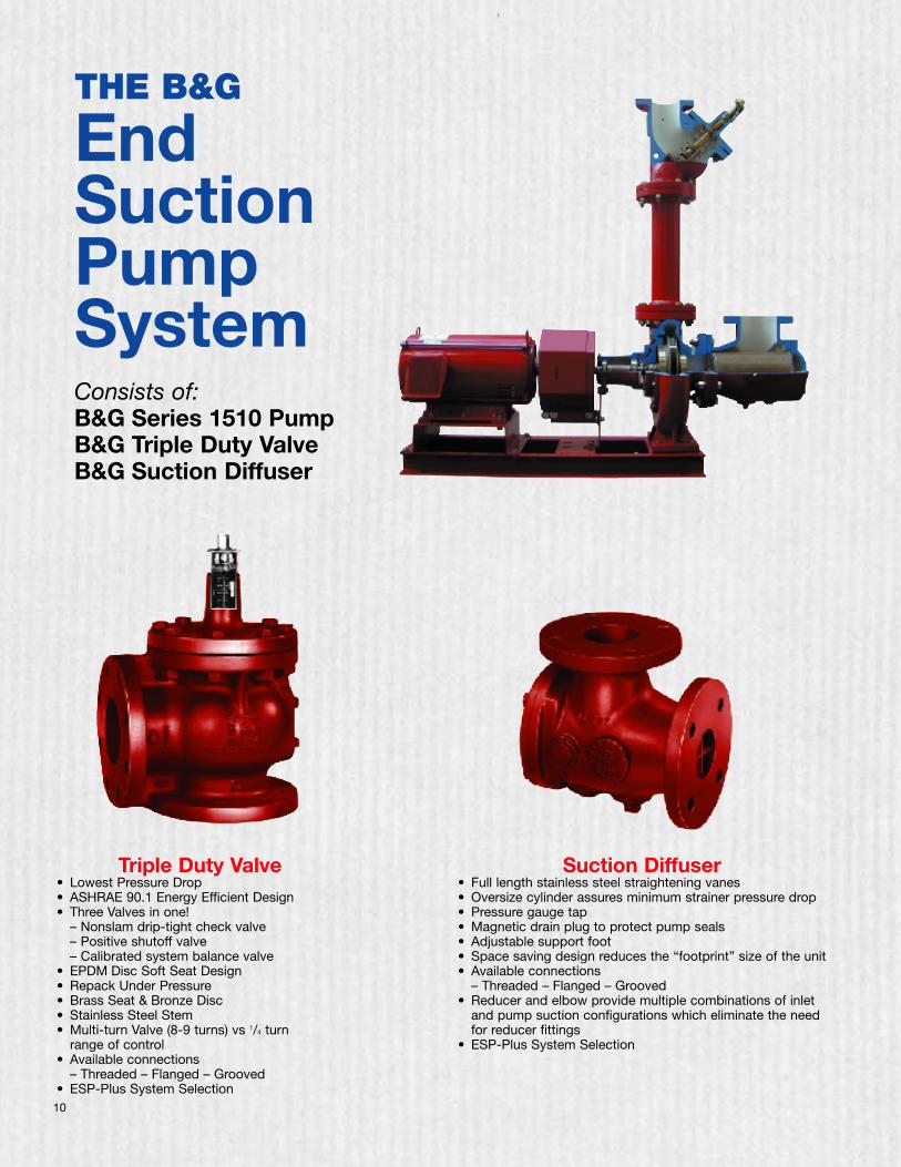
THE B&G
EndSuctionPumpSystemConsists of:B&G Series 1510 PumpB&G Triple Duty ValveB&G Suction Diffuser
Suction Diffuser• Full length stainless steel straightening vanes• Oversize cylinder assures minimum strainer pressure drop• Pressure gauge tap• Magnetic drain plug to protect pump seals• Adjustable support foot• Space saving design reduces the “footprint” size of the unit• Available connections
– Threaded – Flanged – Grooved• Reducer and elbow provide multiple combinations of inlet
and pump suction configurations which eliminate the needfor reducer fittings
• ESP-Plus System Selection
Triple Duty Valve• Lowest Pressure Drop• ASHRAE 90.1 Energy Efficient Design• Three Valves in one!
– Nonslam drip-tight check valve– Positive shutoff valve– Calibrated system balance valve
• EPDM Disc Soft Seat Design• Repack Under Pressure• Brass Seat & Bronze Disc• Stainless Steel Stem• Multi-turn Valve (8-9 turns) vs 1/4 turn
range of control• Available connections
– Threaded – Flanged – Grooved• ESP-Plus System Selection
11
Typical Specification for Series 1510Base Mounted, Flexible Coupled,End-Suction PumpsFurnish and install pumps with performance characteristics asshown on plans. Pumps shall be base mounted, single stage,end suction design with a foot mounted volute to allow removaland service of the entire rotating assembly without disturbingthe pump piping, electrical motor connections or pump to motoralignment.
Pump volute shall be Class 30 cast iron with integrally-castpedestal support feet. The impeller shall be cast bronzeenclosed type, balanced to ANSI/HI 1.1-1.5-1994, section1.4.6.1.3.1, figure 1.106, balance grade G6.3 and keyed to theshaft and secured by a locking capscrew.
The liquid cavity shall be sealed off at the pump shaft by aninternally-flushed mechanical seal with ceramic seal seat andcarbon seal ring, suitable for continuous operation at 225°F(107°C). A replaceable bronze shaft sleeve shall completelycover the wetted area under the seal.
Pump shall be rated for minimum of 175 psi (12 bar) workingpressure. Volute shall have gauge tappings at the suction anddischarge nozzles and vent and drain tappings at the top andbottom.
The pump(s) vibration limits shall conform to Hydraulic InstituteANSI/HI 1.1-1.5-1994, section 1.4.6.1.1 for recommend accept-able unfiltered field vibration limits (as measured perHI 1.4.6.5.2, Figures 1.108) for pumps with rolling contactbearings.
Baseplate shall be of structural steel or fabricated steelchannel with fully enclosed sides and ends, and securelywelded cross members. Grouting area shall be fully open. Thecombined pump and motor baseplate shall be sufficiently stiffas to limit the susceptibility of vibration. The minimum baseplatestiffness shall conform to ANSI/HI 1.3.4-1997 for HorizontalBaseplate Design standards.
The seismic capability of the pump shall allow it to withstand ahorizontal load of 0.5g, excluding piping and/or fasteners usedto anchor the pump to mounting pads or to the floor, withoutadversely affecting pump operation.
A flexible type, center drop-out design coupler, capableof absorbing torsional vibration, shall be employed betweenthe pump and motor. Pumps for variable speed applicationshall be provided with a suitable coupler sleeve. The couplingshall be shielded by a dual rated ANSI B15.1, Section 8 &OSHA 1910.219 compliant coupling guard and contain viewingwindows for inspection of the coupling.
Motor shall meet NEMA and EPACT ’92 (where applicable)specifications and shall be of the size, voltage and enclosurecalled for on the plans. Pump and motor shall be factoryaligned, and shall be realigned by the contractor per factoryrecommendations after installation.
The pump(s) selected shall conform to ANSI/HI 9.6.3.1standards for Preferred Operating Region (POR) unless other-wise approved by the engineer. The pump NPSH shall conformto the ANSI/HI 9.6.1-1997 standards for Centrifugal and VerticalPumps for NPSH Margin.
Each pump shall be factory hydrostatically tested per HydraulicInstitute standards. It shall then be thoroughly cleaned andpainted with at least one coat of high grade paint prior toshipment.
The pump(s) shall be manufactured, assembled and tested in anISO 9001 approved facility.
Pumps shall be Series 1510 as manufactured by ITT Bell &Gossett or equal.