
Bull ESCALA PL 820R - Bull On-line Support...
155
Bull ESCALA PL 820R Installation Guide 86 A1 19EG 01 ORDER REFERENCE
-
Upload
truongmien -
Category
Documents
-
view
217 -
download
0
Transcript of Bull ESCALA PL 820R - Bull On-line Support...

Bull ESCALA PL 820RInstallation Guide
86 A1 19EG 01ORDER REFERENCE


Bull ESCALA PL 820RInstallation Guide
Hardware
May 2003
BULL CEDOC357 AVENUE PATTONB.P.2084549008 ANGERS CEDEX 01FRANCE
86 A1 19EG 01ORDER REFERENCE

The following copyright notice protects this book under the Copyright laws of the United States of Americaand other countries which prohibit such actions as, but not limited to, copying, distributing, modifying, andmaking derivative works.
Copyright Bull S.A. 1992, 2003
Printed in France
Suggestions and criticisms concerning the form, content, and presentation ofthis book are invited. A form is provided at the end of this book for this purpose.
To order additional copies of this book or other Bull Technical Publications, youare invited to use the Ordering Form also provided at the end of this book.
Trademarks and Acknowledgements
We acknowledge the right of proprietors of trademarks mentioned in this book.
AIX� is a registered trademark of International Business Machines Corporation, and is being used underlicence.
UNIX is a registered trademark in the United States of America and other countries licensed exclusively throughthe Open Group.
Linux is a registered trademark of Linus Torvalds.
The information in this document is subject to change without notice. Groupe Bull will not be liable for errorscontained herein, or for incidental or consequential damages in connection with the use of this material.
iiiPreface
Safety Notices
A danger notice indicates the presence of a hazard that has the potential of causing deathor serious personal injury. Danger notices appear on the following pages:
• on page iv
• on page 1-4
• on page 1-18
• on page 4-1
A caution notice indicates the presence of a hazard that has the potential of causingmoderate or minor personal injury. Caution notices appear on the following pages:
• on page iv
• on page v
• on page 1-4
• on page 1-8
• on page 1-19
• on page 4-1
For a translation of the safety notices contained in this book, see the System Unit SafetyInformation, order number 86 X1 11WD.
Rack Safety Instructions• Do not install this unit in a rack where the internal rack ambient temperatures will exceed
40 degrees C.
• Do not install this unit in a rack where the air flow is compromised. Any side, front orback of the unit used for air flow through the unit must not be in direct contact with therack.
• Care should be taken to ensure that a hazardous condition is not created due to unevenmechanical loading when installing this unit in a rack. If the rack has a stabilizer it mustbe firmly attached before installing or removing this unit.
• Consideration should be given to the connection of the equipment to the supply circuit sothat overloading of circuits does not compromise the supply wiring or overcurrentprotection. To provide the correct power connection to the rack, refer to the rating labelslocated on the equipment in the rack to determine the total power requirement for thesupply circuit.
• An electrical outlet that is not correctly wired could place hazardous voltage on the metalparts of the system or the devices that attach to the system. It is the responsibility of thecustomer to ensure that the outlet is correctly wired and grounded to prevent anelectrical shock.
iv ESCALA PL820R Installation Guide
Electrical SafetyObserve the following safety instructions anytime you are connecting or disconnectingdevices attached to the workstation.
DANGER!An electrical outlet that is not correctly wired could place hazardous voltage on metalparts of the system or the devices that attach to the system. It is the responsibility ofthe customer to ensure that the outlet is correctly wired and grounded to prevent anelectrical shock.
Before installing or removing signal cables, ensure that the power cables for thesystem unit and all attached devices are unplugged.
When adding or removing any additional devices to or from the system, ensure thatthe power cables for those devices are unplugged before the signal cables areconnected. If possible, disconnect all power cables from the existing system beforeyou add a device.
Use one hand, when possible, to connect or disconnect signal cables to prevent apossible shock from touching two surfaces with different electrical potentials.
During an electrical storm, do not connect cables for display stations, printers,telephones, or station protectors for communications lines.
DANGER!To prevent electrical shock hazard, disconnect all power cables from the electricaloutlet before relocating the system.
Caution:This product is equipped with a three–wire power cable and plug for the user’ssafety. Use this power cable with a properly grounded electrical outlet to avoidelectrical shock.
Caution:This unit has more than one power supply cord. To reduce the risk of electricalshock, disconnect two power supply cords before servicing.
Caution:This unit weighs more than 55 kg (121.2 pounds). Material handling systems such aslevers, slings, or lifts are required to safely move it. When this is not possible,specially trained persons or services (such as riggers or movers) must be used.
vPreface
Laser Safety Information
Caution:This product may contain a CD–ROM, DVD–ROM, or laser module on a PCI card,which are class 1 laser products.
Laser ComplianceAll lasers are certified in the U.S. to conform to the requirements of DHHS 21 CFRSubchapter J for class 1 laser products. Outside the U.S., they are certified to be incompliance with the IEC 825 (first edition 1984) as a class 1 laser product. Consult the labelon each part for laser certification numbers and approval information.
Caution:All laser modules are designed so that there is never any human access to laserradiation above a class 1 level during normal operation, user maintenance, orprescribed service conditions. Data processing environments can contain equipmenttransmitting on system links with laser modules that operate at greater than class 1power levels. For this reason, never look into the end of an optical fiber cable or openreceptacle. Only trained service personnel should perform the inspection or repair ofoptical fiber cable assemblies and receptacles.

vi ESCALA PL820R Installation Guide
Data Integrity and Verification
These computer systems contain mechanisms designed to reduce the possibility ofundetected data corruption or loss. This risk, however, cannot be eliminated. Userswho experience unplanned outages, system failures, power fluctuations or outages,or component failures must verify the accuracy of operations performed and datasaved or transmitted by the system at or near the time of the outage or failure. Inaddition, users must establish procedures to ensure that there is independent dataverification before relying on such data in sensitive or critical operations. Usersshould periodically check our support websites for updated information and fixesapplicable to the system and related software.
viiPreface
About This Book
This book provides information on how to set up and cable the server, install and removeoptions, and verify server operation.
ISO 9000ISO 9001 registered quality systems were used in the development and manufacturing ofthis product.
HighlightingThe following highlighting conventions are used in this book:
Bold Identifies commands, subroutines, keywords, files, structures,directories, and other items whose names are predefined by thesystem. Also identifies graphical objects such as buttons, labels, andicons that the user selects.
Italics Identifies parameters whose actual names or values are to be suppliedby the user.
Monospace Identifies examples of specific data values, examples of text similar towhat you might see displayed, examples of portions of program codesimilar to what you might write as a programmer, messages from thesystem, or information you should actually type.
Related PublicationsThe following publications provide related information:
• The System Unit Safety Information, order number 86 X1 11WD, contains translations ofsafety information used throughout this book.
• The HMC Installation and Operations Guide, order number 86 A1 83EF, providesinformation to system administrators on how to install and use a Hardware ManagementConsole (HMC) to manage a system.
• The ESCALA PL820R Service Guide, order number 86 A1 21EG, contains referenceinformation, maintenance analysis procedures (MAPs), error codes, removal andreplacement procedures, and a parts catalog.
• The ESCALA PL820R User’s Guide, order number 86 A1 20EG, contains information onhow to use the system, use diagnostics, use service aids, and verify system operations.
• The D10 I/O Drawer Installation Guide, order number 86 A1 32EG, contains informationabout installing the D10 I/O Drawer.
• The D20 I/O Drawer Installation Guide, order number 86 A1 39EG, contains informationabout installing the D20 I/O Drawer.
• The Diagnostic Information for Multiple Bus Systems, order number 86 A1 26HX,contains diagnostic information, service request numbers (SRNs), and failing functioncodes (FFCs).

viii ESCALA PL820R Installation Guide
• The Adapters Information for Multiple Bus Systems, order number 86 A1 27HX, containsinformation about adapters, devices, and cables for your server. This manual is intendedto supplement the service information found in the Diagnostic Information for MultipleBus Systems.
• The Site Preparation for Rack Systems, order number 86 A1 30PX, contains informationto help you plan your installation.
ixPreface
Table of Contents
Safety Notices iii. . . . . . . . . . . . . . . . . . . . . . . . . . . . . . . . . . . . . . . . . . . . . . . . . . . . . . . . . . Rack Safety Instructions iii. . . . . . . . . . . . . . . . . . . . . . . . . . . . . . . . . . . . . . . . . . . . . . . . . . Electrical Safety iv. . . . . . . . . . . . . . . . . . . . . . . . . . . . . . . . . . . . . . . . . . . . . . . . . . . . . . . . . Laser Safety Information v. . . . . . . . . . . . . . . . . . . . . . . . . . . . . . . . . . . . . . . . . . . . . . . . . .
Laser Compliance v. . . . . . . . . . . . . . . . . . . . . . . . . . . . . . . . . . . . . . . . . . . . . . . . . . . . .
Data Integrity and Verification vi. . . . . . . . . . . . . . . . . . . . . . . . . . . . . . . . . . . . . . . . . . .
About This Book vii. . . . . . . . . . . . . . . . . . . . . . . . . . . . . . . . . . . . . . . . . . . . . . . . . . . . . . . . ISO 9000 vii. . . . . . . . . . . . . . . . . . . . . . . . . . . . . . . . . . . . . . . . . . . . . . . . . . . . . . . . . . . . . . . Highlighting vii. . . . . . . . . . . . . . . . . . . . . . . . . . . . . . . . . . . . . . . . . . . . . . . . . . . . . . . . . . . . . Related Publications vii. . . . . . . . . . . . . . . . . . . . . . . . . . . . . . . . . . . . . . . . . . . . . . . . . . . . .
Chapter 1. Installing the ESCALA PL820R 1-1. . . . . . . . . . . . . . . . . . . . . . . . . . . . . . . . ESCALA PL820R Overview 1-1. . . . . . . . . . . . . . . . . . . . . . . . . . . . . . . . . . . . . . . . . . . . . . Before You Begin 1-2. . . . . . . . . . . . . . . . . . . . . . . . . . . . . . . . . . . . . . . . . . . . . . . . . . . . . . . . Step 1. Check Your Inventory 1-2. . . . . . . . . . . . . . . . . . . . . . . . . . . . . . . . . . . . . . . . . . . . . . Step 2. Read the Safety Notices 1-4. . . . . . . . . . . . . . . . . . . . . . . . . . . . . . . . . . . . . . . . . . . Step 3. Attach the Mounting Hardware to the Rack Enclosure 1-5. . . . . . . . . . . . . . . . . . Step 4. Install the System in the Rack Enclosure 1-8. . . . . . . . . . . . . . . . . . . . . . . . . . . . . Step 5. Are All of the Features Installed? 1-10. . . . . . . . . . . . . . . . . . . . . . . . . . . . . . . . . . . . Step 6. Position the Display 1-10. . . . . . . . . . . . . . . . . . . . . . . . . . . . . . . . . . . . . . . . . . . . . . . Step 7. Check Your Display or Console Type 1-11. . . . . . . . . . . . . . . . . . . . . . . . . . . . . . . . Step 8. Connecting to a Hardware Management Console (HMC) 1-11. . . . . . . . . . . . . . . Step 9. Attach the Display Cable Toroid 1-12. . . . . . . . . . . . . . . . . . . . . . . . . . . . . . . . . . . . . Step 10. Connect the Graphics Display 1-12. . . . . . . . . . . . . . . . . . . . . . . . . . . . . . . . . . . . . Step 11. Connect the Keyboard and Mouse (When Using a Graphics Display) 1-13. . . Step 12. Connect the Serial and Parallel Devices 1-14. . . . . . . . . . . . . . . . . . . . . . . . . . . . Step 13. Connect the Adapter Cables 1-16. . . . . . . . . . . . . . . . . . . . . . . . . . . . . . . . . . . . . . Step 14. Connect the External SCSI Device 1-16. . . . . . . . . . . . . . . . . . . . . . . . . . . . . . . . . Step 15. Are You Using the Rack Indicator Feature? 1-17. . . . . . . . . . . . . . . . . . . . . . . . . . Step 16. Are You Using an Ethernet Connection? 1-18. . . . . . . . . . . . . . . . . . . . . . . . . . . . Step 17. Connect the Power Cords to the Server 1-18. . . . . . . . . . . . . . . . . . . . . . . . . . . . . Step 18. Route the Cables 1-19. . . . . . . . . . . . . . . . . . . . . . . . . . . . . . . . . . . . . . . . . . . . . . . . Step 19. Connect the Power Cords 1-20. . . . . . . . . . . . . . . . . . . . . . . . . . . . . . . . . . . . . . . . . Step 20. What is the Next Step? 1-21. . . . . . . . . . . . . . . . . . . . . . . . . . . . . . . . . . . . . . . . . . .
Chapter 2. Verifying the Hardware Operation 2-1. . . . . . . . . . . . . . . . . . . . . . . . . . . . . . Considerations Before Running This Procedure 2-1. . . . . . . . . . . . . . . . . . . . . . . . . . . . . .
Power Procedures 2-1. . . . . . . . . . . . . . . . . . . . . . . . . . . . . . . . . . . . . . . . . . . . . . . . . . . . . Using the HMC to Load the Online Diagnostics in Service Mode 2-4. . . . . . . . . . . . . . . Using the HMC to Load the Standalone Diagnostics from CD–ROM 2-4. . . . . . . . . . . . Loading the Online Diagnostics on a System without an HMC Attached 2-5. . . . . . . . . Loading the Standalone Diagnostics on a System without an HMC Attached 2-5. . . . . Running Standalone Diagnostics from a Network Installation Management (NIM) Server withan HMC Attached to the System 2-6. . . . . . . . . . . . . . . . . . . . . . . . . . . . . . . . . . . . . . . . . . .
NIM Server Configuration 2-6. . . . . . . . . . . . . . . . . . . . . . . . . . . . . . . . . . . . . . . . . . . . . . . Client Configuration and Booting Standalone Diagnostics from the NIM Server 2-7
Running System Verification 2-8. . . . . . . . . . . . . . . . . . . . . . . . . . . . . . . . . . . . . . . . . . . . . . . Performing Additional System Verification 2-8. . . . . . . . . . . . . . . . . . . . . . . . . . . . . . . . . . .

x ESCALA PL820R Installation Guide
Stopping the Diagnostics 2-8. . . . . . . . . . . . . . . . . . . . . . . . . . . . . . . . . . . . . . . . . . . . . . . . . Verify that the Latest Firmware and Adapter and Drive Microcode are Installed 2-9. . . Verify that the Latest HMC Software is Installed 2-9. . . . . . . . . . . . . . . . . . . . . . . . . . . . . . Verify Partition Standby and Full System Partition Power Options 2-9. . . . . . . . . . . . . . Final Installation Tasks 2-10. . . . . . . . . . . . . . . . . . . . . . . . . . . . . . . . . . . . . . . . . . . . . . . . . . .
Complete System Records and Installation Procedure 2-10. . . . . . . . . . . . . . . . . . . . . . Configure the Network 2-10. . . . . . . . . . . . . . . . . . . . . . . . . . . . . . . . . . . . . . . . . . . . . . . . .
Chapter 3. Completing the Installation 3-1. . . . . . . . . . . . . . . . . . . . . . . . . . . . . . . . . . . . Step 1. Bezels and Doors 3-1. . . . . . . . . . . . . . . . . . . . . . . . . . . . . . . . . . . . . . . . . . . . . . . . . Step 2. Complete Installation Checklists 3-1. . . . . . . . . . . . . . . . . . . . . . . . . . . . . . . . . . . .
TTY Terminal Console and the System is Not Partitioned 3-1. . . . . . . . . . . . . . . . . . . Graphics Terminal Console and the System is Not Partitioned 3-2. . . . . . . . . . . . . . . HMC–Managed System Using a Single Full System Partition 3-3. . . . . . . . . . . . . . . . HMC–Managed System with Multiple Partitions 3-5. . . . . . . . . . . . . . . . . . . . . . . . . . .
Chapter 4. Installing Options for the ESCALA PL 820R 4-1. . . . . . . . . . . . . . . . . . . . Safety Considerations 4-1. . . . . . . . . . . . . . . . . . . . . . . . . . . . . . . . . . . . . . . . . . . . . . . . . . . . Handling Static–Sensitive Devices 4-2. . . . . . . . . . . . . . . . . . . . . . . . . . . . . . . . . . . . . . . . . Color Coded Indicators 4-2. . . . . . . . . . . . . . . . . . . . . . . . . . . . . . . . . . . . . . . . . . . . . . . . . . . Stopping the System 4-3. . . . . . . . . . . . . . . . . . . . . . . . . . . . . . . . . . . . . . . . . . . . . . . . . . . . . Disk Drive Options 4-3. . . . . . . . . . . . . . . . . . . . . . . . . . . . . . . . . . . . . . . . . . . . . . . . . . . . . . .
Preinstallation Considerations for Disk Drives 4-4. . . . . . . . . . . . . . . . . . . . . . . . . . . . . Installing Hot–Plug SCSI Disk Drives 4-4. . . . . . . . . . . . . . . . . . . . . . . . . . . . . . . . . . . . . Removing Hot–Plug SCSI Disk Drives 4-6. . . . . . . . . . . . . . . . . . . . . . . . . . . . . . . . . . . . Configuring and Deconfiguring SCSI Hot–Swap Disk Drives 4-7. . . . . . . . . . . . . . . .
Installing Media Drives 4-8. . . . . . . . . . . . . . . . . . . . . . . . . . . . . . . . . . . . . . . . . . . . . . . . . . . Installing a Drive in the Optional Media Position 4-8. . . . . . . . . . . . . . . . . . . . . . . . . . .
PCI Adapters 4-9. . . . . . . . . . . . . . . . . . . . . . . . . . . . . . . . . . . . . . . . . . . . . . . . . . . . . . . . . . . . Non–Hot–Pluggable PCI Adapter 4-10. . . . . . . . . . . . . . . . . . . . . . . . . . . . . . . . . . . . . . . . Hot–Pluggable PCI Adapter 4-12. . . . . . . . . . . . . . . . . . . . . . . . . . . . . . . . . . . . . . . . . . . . . PCI Adapter or Blank Filler Removal from a Cassette Assembly 4-15. . . . . . . . . . . . . Replacing an Adapter in a PCI Adapter Cassette 4-25. . . . . . . . . . . . . . . . . . . . . . . . . . Short Adapter or Blank Filler Installation 4-29. . . . . . . . . . . . . . . . . . . . . . . . . . . . . . . . . . Long Adapter Installation 4-43. . . . . . . . . . . . . . . . . . . . . . . . . . . . . . . . . . . . . . . . . . . . . . . Replacing a Hot–Pluggable PCI Adapter 4-57. . . . . . . . . . . . . . . . . . . . . . . . . . . . . . . . .
Appendix A. Communications Statements A-1. . . . . . . . . . . . . . . . . . . . . . . . . . . . . . . . Federal Communications Commission (FCC) Statement A-1. . . . . . . . . . . . . . . . . . . . . . European Union (EU) Statement A-1. . . . . . . . . . . . . . . . . . . . . . . . . . . . . . . . . . . . . . . . . . . International Electrotechnical Commission (IEC) Statement A-1. . . . . . . . . . . . . . . . . . . United Kingdom Telecommunications Safety Requirements A-2. . . . . . . . . . . . . . . . . . . Avis de conformité aux normes du ministère des Communications du Canada A-2. . . Canadian Department of Communications Compliance Statement A-2. . . . . . . . . . . . . VCCI Statement A-2. . . . . . . . . . . . . . . . . . . . . . . . . . . . . . . . . . . . . . . . . . . . . . . . . . . . . . . . . Electromagnetic Interference (EMI) Statement – Taiwan A-3. . . . . . . . . . . . . . . . . . . . . . Radio Protection for Germany A-3. . . . . . . . . . . . . . . . . . . . . . . . . . . . . . . . . . . . . . . . . . . . .
Appendix B. Environmental Notices B-1. . . . . . . . . . . . . . . . . . . . . . . . . . . . . . . . . . . . . . Product Recycling and Disposal B-1. . . . . . . . . . . . . . . . . . . . . . . . . . . . . . . . . . . . . . . . . . . Acoustical Noise Emissions B-2. . . . . . . . . . . . . . . . . . . . . . . . . . . . . . . . . . . . . . . . . . . . . . .
Declared Acoustical Noise Emissions B-2. . . . . . . . . . . . . . . . . . . . . . . . . . . . . . . . . . . .
xiPreface
Appendix C. PCI Adapter Placement Reference C-1. . . . . . . . . . . . . . . . . . . . . . . . . . . Logical Partition (LPAR) Considerations C-1. . . . . . . . . . . . . . . . . . . . . . . . . . . . . . . . . . . . PL820R Adapter Placement Guide C-2. . . . . . . . . . . . . . . . . . . . . . . . . . . . . . . . . . . . . . . . .
Appendix D. Subsystem Positioning and Cabling D-1. . . . . . . . . . . . . . . . . . . . . . . . . SPCN Cabling D-1. . . . . . . . . . . . . . . . . . . . . . . . . . . . . . . . . . . . . . . . . . . . . . . . . . . . . . . . . . .
One I/O Subsystem, Two I/O Subsystems D-1. . . . . . . . . . . . . . . . . . . . . . . . . . . . . . . . Four I/O Subsystems, Eight I/O Subsystems D-2. . . . . . . . . . . . . . . . . . . . . . . . . . . . . .
RIO Cabling D-4. . . . . . . . . . . . . . . . . . . . . . . . . . . . . . . . . . . . . . . . . . . . . . . . . . . . . . . . . . . . . One I/O Subsystem or Two I/O Subsystems D-4. . . . . . . . . . . . . . . . . . . . . . . . . . . . . . Three I/O Subsystems or Four I/O Subsystems D-5. . . . . . . . . . . . . . . . . . . . . . . . . . . . Eight I/O Subsystems with Two RIO Loops D-7. . . . . . . . . . . . . . . . . . . . . . . . . . . . . . .
Hardware Management Console (HMC) to the HMC Connector D-8. . . . . . . . . . . . . . . . Optional 8–Port or 128–Port Async Adapters D-8. . . . . . . . . . . . . . . . . . . . . . . . . . . . . .
Appendix E. Service Processor Setup and Test E-1. . . . . . . . . . . . . . . . . . . . . . . . . . . Service Processor Setup Checklist E-1. . . . . . . . . . . . . . . . . . . . . . . . . . . . . . . . . . . . . . . . . Testing the Setup E-1. . . . . . . . . . . . . . . . . . . . . . . . . . . . . . . . . . . . . . . . . . . . . . . . . . . . . . . .
Testing Call–In E-2. . . . . . . . . . . . . . . . . . . . . . . . . . . . . . . . . . . . . . . . . . . . . . . . . . . . . . . . Testing Call–Out E-2. . . . . . . . . . . . . . . . . . . . . . . . . . . . . . . . . . . . . . . . . . . . . . . . . . . . . . . Serial Port Configuration E-2. . . . . . . . . . . . . . . . . . . . . . . . . . . . . . . . . . . . . . . . . . . . . . .
Appendix F. Firmware Updates F-1. . . . . . . . . . . . . . . . . . . . . . . . . . . . . . . . . . . . . . . . . . General Information on System Firmware Updates F-1. . . . . . . . . . . . . . . . . . . . . . . . . . . Determining the Level of Firmware on the System F-1. . . . . . . . . . . . . . . . . . . . . . . . . . . . Updating System Firmware From the Service Processor Menus F-2. . . . . . . . . . . . . . . Updating System Firmware from a NIM Server F-2. . . . . . . . . . . . . . . . . . . . . . . . . . . . . . . Recovery Mode F-2. . . . . . . . . . . . . . . . . . . . . . . . . . . . . . . . . . . . . . . . . . . . . . . . . . . . . . . . . .
Appendix G. System Records G-1. . . . . . . . . . . . . . . . . . . . . . . . . . . . . . . . . . . . . . . . . . . . Record the Identification Numbers G-1. . . . . . . . . . . . . . . . . . . . . . . . . . . . . . . . . . . . . . . . . Device Records G-2. . . . . . . . . . . . . . . . . . . . . . . . . . . . . . . . . . . . . . . . . . . . . . . . . . . . . . . . .
Index X-1. . . . . . . . . . . . . . . . . . . . . . . . . . . . . . . . . . . . . . . . . . . . . . . . . . . . . . . . . . . . . . . . . .

xii ESCALA PL820R Installation Guide
1-1Installing the Escala PL820R
Chapter 1. Installing the ESCALA PL820R
Use the procedures in this chapter to set up your ESCALA PL820R.
Note: This procedure explains how to attach the mounting hardware to the rackenclosure. If your ESCALA PL820R was preinstalled in the rack, performthe rack–installation procedures as described in the T00 and T42 RackInstallation and Service Guide, order number 86 A1 94KX.
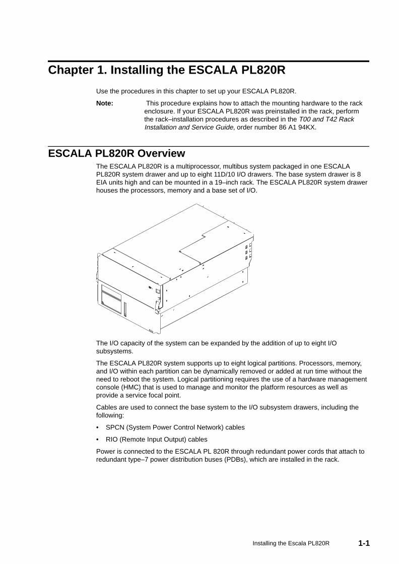
ESCALA PL820R OverviewThe ESCALA PL820R is a multiprocessor, multibus system packaged in one ESCALAPL820R system drawer and up to eight 11D/10 I/O drawers. The base system drawer is 8EIA units high and can be mounted in a 19–inch rack. The ESCALA PL820R system drawerhouses the processors, memory and a base set of I/O.
The I/O capacity of the system can be expanded by the addition of up to eight I/Osubsystems.
The ESCALA PL820R system supports up to eight logical partitions. Processors, memory,and I/O within each partition can be dynamically removed or added at run time without theneed to reboot the system. Logical partitioning requires the use of a hardware managementconsole (HMC) that is used to manage and monitor the platform resources as well asprovide a service focal point.
Cables are used to connect the base system to the I/O subsystem drawers, including thefollowing:
• SPCN (System Power Control Network) cables
• RIO (Remote Input Output) cables
Power is connected to the ESCALA PL 820R through redundant power cords that attach toredundant type–7 power distribution buses (PDBs), which are installed in the rack.
1-2 Escala PL820R Installation Guide
Before You BeginTo ensure that all of the installation steps are complete, the installer should use the followinginstallation checklists during the installation process. The customer’s choice of systemconsole options and partition configurations determines which of the following checklists touse. At the appropriate points in the installation steps, you will be referred to the applicablechecklist.
Note: If the system you are installing will be managed by an HMC, and the HMC is notinstalled and functional, see the Hardware Management Console Installation andOperations Guide, order number 86 A1 83EF, for instructions on installing the HMC.Install the HMC, then return here and continue with this procedure.
• TTY Terminal Console and the System is Not Partitioned on page 3-1
• Graphics Terminal Console and the System is Not Partitioned on page 3-2
• HMC–Managed System Using a Single Full System Partition on page 3-3
• HMC–Managed System with Multiple Partitions on page 3-5
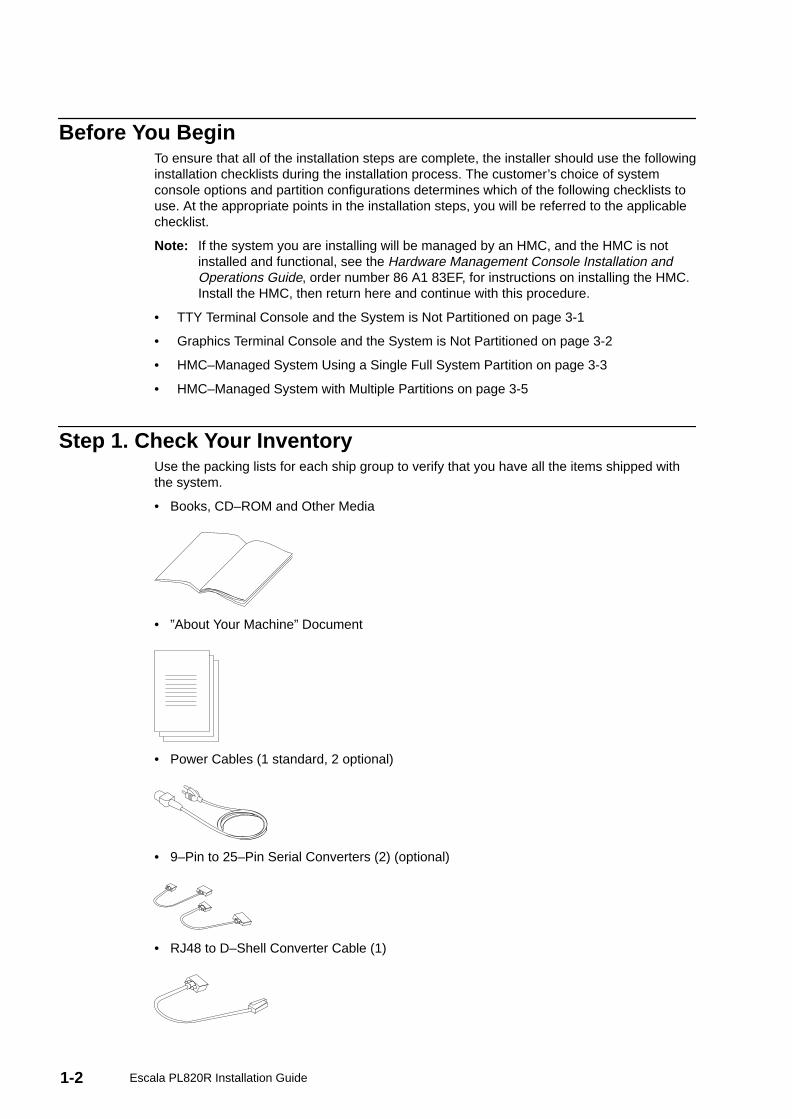
Step 1. Check Your InventoryUse the packing lists for each ship group to verify that you have all the items shipped withthe system.
• Books, CD–ROM and Other Media
• ”About Your Machine” Document
• Power Cables (1 standard, 2 optional)
• 9–Pin to 25–Pin Serial Converters (2) (optional)
• RJ48 to D–Shell Converter Cable (1)
1-3Installing the Escala PL820R
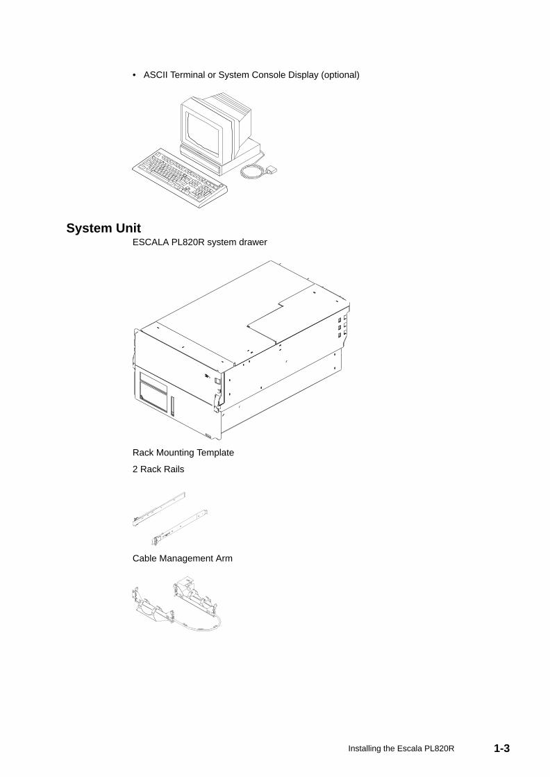
• ASCII Terminal or System Console Display (optional)
System UnitESCALA PL820R system drawer
Rack Mounting Template
2 Rack Rails
Cable Management Arm
1-4 Escala PL820R Installation Guide
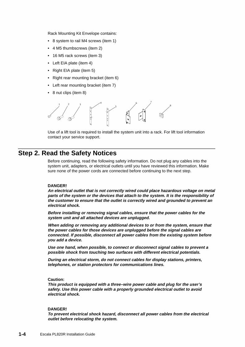
Rack Mounting Kit Envelope contains:
• 8 system to rail M4 screws (item 1)
• 4 M5 thumbscrews (item 2)
• 16 M5 rack screws (item 3)
• Left EIA plate (item 4)
• Right EIA plate (item 5)
• Right rear mounting bracket (item 6)
• Left rear mounting bracket (item 7)
• 8 nut clips (item 8)
1 2 34
56 7
8
Use of a lift tool is required to install the system unit into a rack. For lift tool informationcontact your service support.
Step 2. Read the Safety NoticesBefore continuing, read the following safety information. Do not plug any cables into thesystem unit, adapters, or electrical outlets until you have reviewed this information. Makesure none of the power cords are connected before continuing to the next step.
DANGER!An electrical outlet that is not correctly wired could place hazardous voltage on metalparts of the system or the devices that attach to the system. It is the responsibility ofthe customer to ensure that the outlet is correctly wired and grounded to prevent anelectrical shock.
Before installing or removing signal cables, ensure that the power cables for thesystem unit and all attached devices are unplugged.
When adding or removing any additional devices to or from the system, ensure thatthe power cables for those devices are unplugged before the signal cables areconnected. If possible, disconnect all power cables from the existing system beforeyou add a device.
Use one hand, when possible, to connect or disconnect signal cables to prevent apossible shock from touching two surfaces with different electrical potentials.
During an electrical storm, do not connect cables for display stations, printers,telephones, or station protectors for communications lines.
Caution:This product is equipped with a three–wire power cable and plug for the user’ssafety. Use this power cable with a properly grounded electrical outlet to avoidelectrical shock.
DANGER!To prevent electrical shock hazard, disconnect all power cables from the electricaloutlet before relocating the system.
1-5Installing the Escala PL820R
Step 3. Attach the Mounting Hardware to the Rack EnclosureTo attach the mounting hardware, you will need the following items:
• Rack–Mounting Template
• 2 Rack Rails
• Cable Management Arm
• Rack–Mounting Kit Envelope
• Screwdriver or Nutdriver
1. Install the slide–rails and the cable management arm on the mounting rails of the rackenclosure.
Note: If you do not have the rail template, go to Rail Positioning Without aTemplate on page 1-8.You must align the rack slide rails correctly.Otherwise, the installation cannot be completed successfully.
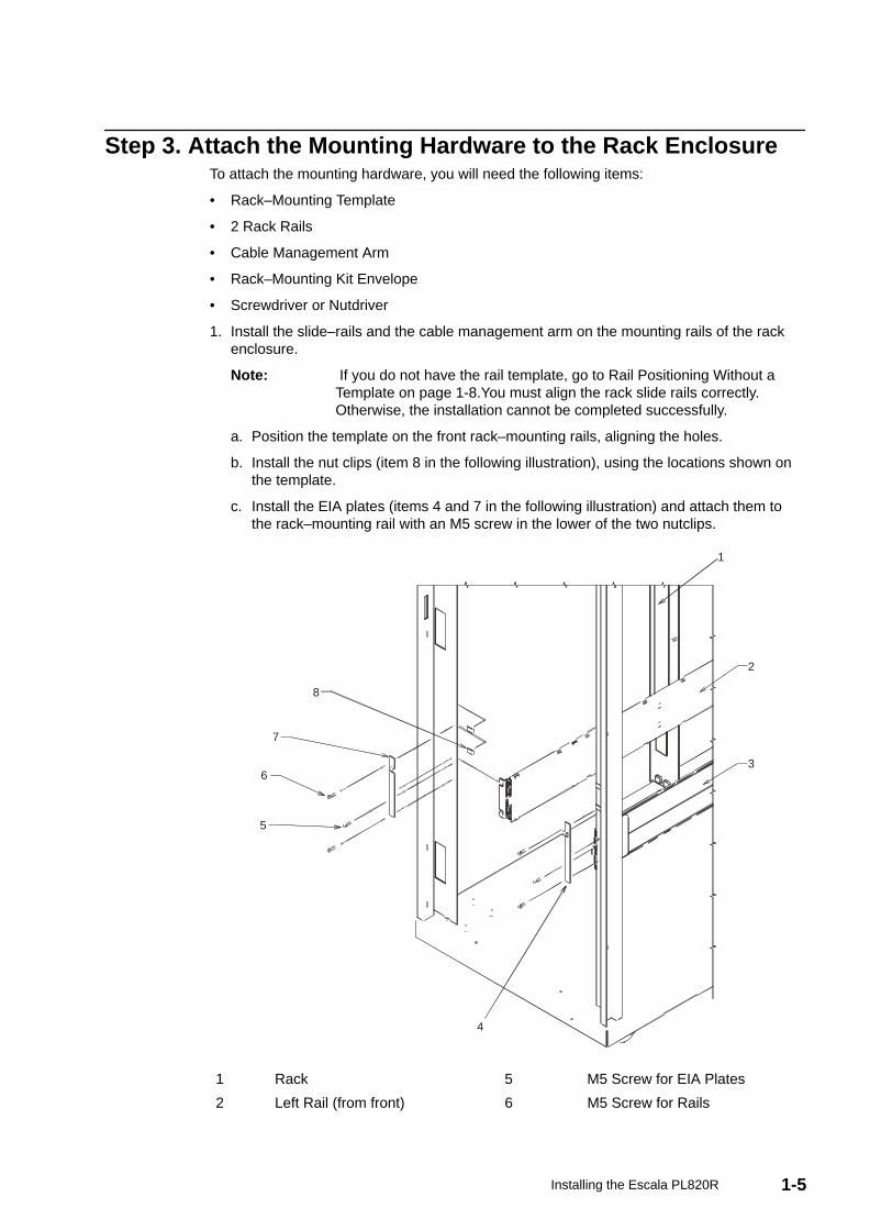
a. Position the template on the front rack–mounting rails, aligning the holes.
b. Install the nut clips (item 8 in the following illustration), using the locations shown onthe template.
c. Install the EIA plates (items 4 and 7 in the following illustration) and attach them tothe rack–mounting rail with an M5 screw in the lower of the two nutclips.
8
7
5
6
4
3
2
1
1 Rack 5 M5 Screw for EIA Plates
2 Left Rail (from front) 6 M5 Screw for Rails
1-6 Escala PL820R Installation Guide
3 Right Rail (from front) 7 Left EIA Plate (from front)
4 Right EIA Plate (from front) 8 M5 Nut Clip
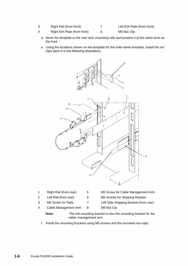
d. Move the template to the rear rack–mounting rails and position it at the same level asthe front.
e. Using the locations shown on the template for the hold–down brackets, install the nutclips (item 8 in the following illustration).
1
4
5
6
7 81
2
3
1 Right Rail (from rear) 5 M5 Screw for Cable Management Arm
2 Left Rail (from rear) 6 M5 Screws for Shipping Bracket
3 M5 Screw for Rails 7 Left Side Shipping Bracket (from rear)
4 Cable Management Arm 8 M5 Nut Cip
Note: The left mounting bracket is also the mounting bracket for thecable–management arm.
f. Install the mounting brackets using M5 screws and the mounted nut–clips.
1-7Installing the Escala PL820R
2. Attach the slide rails to the rack.
a. Insert the left slide–rail so that the pin on the rear end of the slide–rail engages theappropriate hole in the rear–mounting rail. Refer to the template for the alignmenthole. The front end of the slide rail has an L–shape channel in the front flange that fitsover the pin on the EIA plate. Secure the front and rear ends of each slide rail using atotal of eight M5 screws.
b. Perform the step above for the right slide–rail.
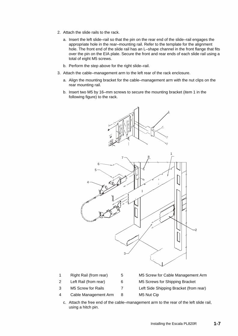
3. Attach the cable–management arm to the left rear of the rack enclosure.
a. Align the mounting bracket for the cable–management arm with the nut clips on therear mounting rail.
b. Insert two M5 by 16–mm screws to secure the mounting bracket (item 1 in thefollowing figure) to the rack.
1
4
5
6
7 81
2
3
1 Right Rail (from rear) 5 M5 Screw for Cable Management Arm
2 Left Rail (from rear) 6 M5 Screws for Shipping Bracket
3 M5 Screw for Rails 7 Left Side Shipping Bracket (from rear)
4 Cable Management Arm 8 M5 Nut Cip
c. Attach the free end of the cable–management arm to the rear of the left slide rail,using a hitch pin.
1-8 Escala PL820R Installation Guide
Rail Positioning Without a TemplateIf you do not have a rack–mounting template, do the following:
1. Determine where in the rack to place the system unit. The system unit you are about toinstall measures 8 EIA units high. Make note of the EIA location number.
Note : An EIA unit on your rack consists of a grouping of three holes.
2. Facing the front of the rack and working from the right side, place a self–adhesive dotnext to the top hole of the bottom EIA unit.
Note: The self–adhesive dots are used to aid in identifying locations on therack. If you no longer have any of the dots, use some other form ofmarking tool to aid you in identifying hole locations (for example, tape, amarker, or pencil).
3. Place another self–adhesive dot next to the top hole of the above EIA unit.
Note : If you are counting the holes, begin with the hole identified by the firstdot and count up four holes. Place the second dot next to the fourthhole.
4. Secure a nut clip to the rack four holes up from the top dot (bottom hole of the top EIAunit). The nut clip aids in securing your system drawer to the rack while in transit.
Notes :
a. If you are counting the holes, begin with the hole identified by the top dot and countup four holes. Place the nut clip next to the fourth hole.
b. Whenever a populated rack is being moved, secure the system drawers with tworetaining thumbscrews threaded through the nut clips. This action secures the systemfront bezel and system chassis to the rack.
c. When counting from the nut clip to the bottom dot, there is an 8–hole span.
5. Repeat this process for the left side of the rack.
Step 4. Install the System in the Rack EnclosureCaution:The stabilizer must be firmly attached to the bottom front of the rack to prevent therack from turning over when the drawers are pulled out of the rack. Do not pull out orinstall any drawer or feature if the stabilizer is not attached to the rack.
Attention: When installing this unit in a rack, ensure that a hazardous condition is notcreated due to uneven mechanical loading. If the rack has a stabilizer, the stablilizer mustbe firmly attached before installing or removing this unit.
Attention: This procedure requires use of a lift tool.
1. Mount the server on the slide rails as follows.
a. Extend the slide rails fully from the rack until the slide rails lock.
b. Using a lift tool, lift the server and position it so that the rails align with the rack–railholes.
c. Slide the server backward or forward as necessary until the rail holes align with theholes in the side of the server.
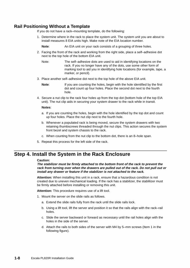
d. Attach the rails to both sides of the server with M4 by 5–mm screws (Item 1 in thefollowing figure).
1-9Installing the Escala PL820R
1
1 M4 by 5–mm Screws
2. Press the safety latches on the slide rails, and slide the server about halfway into therack enclosure.
Note: When the server is fully extended, safety latches on the slide rails lockinto place. This action prevents the server from being accidentally pulledout too far. To release the safety latches, press the latches from insidethe rack.
3. Slide the server fully into the rack enclosure until the slide latches on the front chassisbrackets click into place.
Note: To release the server, release the left and right slide latches and pull theserver forward.
1-10 Escala PL820R Installation Guide
1
1
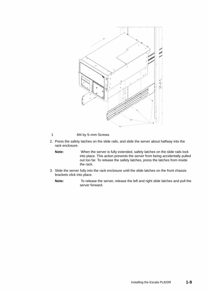
1 Slide Latches
4. (Optional) For additional security, such as needed when transporting the rack, fasten theserver to the rack enclosure by inserting an M5 screw through the chassis bracket,mounting rail, and cage nut on each side. Also, a thumb screw can be used with thehold–down brackets on the rear of the rack to secure the rear of the server.
Step 5. Are All of the Features Installed?The D10 I/O Subsystem is a 19–inch rack–mountable expansion drawer that is designed tobe attached to the ESCALA PL820R system drawer. Two 11D/10 drawers can fit side byside in a single 4U rack enclosure. If you are installing these I/O drawers, refer to theInstallation Guide for the D10 D10 I/O Drawer Installation Guide, order number 86 A1 32EGfor more information.
The D20 I/O Subsystem is a 19–inch rack–mountable expansion drawer that also can beattached to the 386/50 system drawer. A single D20 occupies a full 19” 4U rack position. Ifyou are installing these I/O drawers, refer to the D20 I/O Drawer Installation Guide, ordernumber 86 A1 39EG, for more information.
If you have internal options that are not installed, install them now. Refer to Chapter 4,Installing Options for the ESCALA PL820R and then return here.
Step 6. Position the DisplayIf your system will be connected to a graphics display, position the display at or near itsinstalled location. Place the display or ASCII terminal in a stable and sturdy location.
1-11Installing the Escala PL820R
Step 7. Check Your Display or Console TypeIf you are using an ASCII terminal and keyboard as the console for this system, and do nothave a graphics display to connect, continue with Step 12. Connect the Serial and ParallelDevices on page 1-14.
If you are using a graphics display with a keyboard and mouse, continue with Step 9. Attachthe Display Cable Toroid on page 1-12.
If you are connecting to a Hardware Management Console (HMC), continue with Step 8.Connecting to a Hardware Management Console (HMC) on page 1-11.
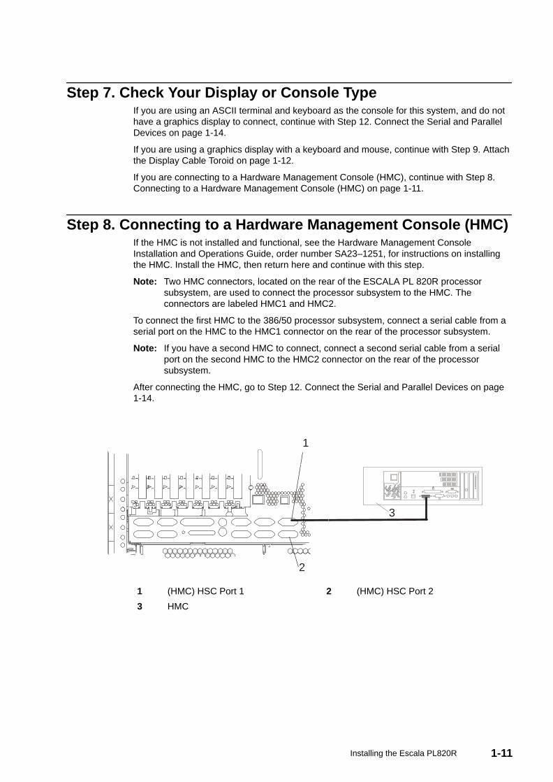
Step 8. Connecting to a Hardware Management Console (HMC)If the HMC is not installed and functional, see the Hardware Management ConsoleInstallation and Operations Guide, order number SA23–1251, for instructions on installingthe HMC. Install the HMC, then return here and continue with this step.
Note: Two HMC connectors, located on the rear of the ESCALA PL 820R processorsubsystem, are used to connect the processor subsystem to the HMC. Theconnectors are labeled HMC1 and HMC2.
To connect the first HMC to the 386/50 processor subsystem, connect a serial cable from aserial port on the HMC to the HMC1 connector on the rear of the processor subsystem.
Note: If you have a second HMC to connect, connect a second serial cable from a serialport on the second HMC to the HMC2 connector on the rear of the processorsubsystem.
After connecting the HMC, go to Step 12. Connect the Serial and Parallel Devices on page1-14.
1
2
3
1 (HMC) HSC Port 1 2 (HMC) HSC Port 2
3 HMC
1-12 Escala PL820R Installation Guide
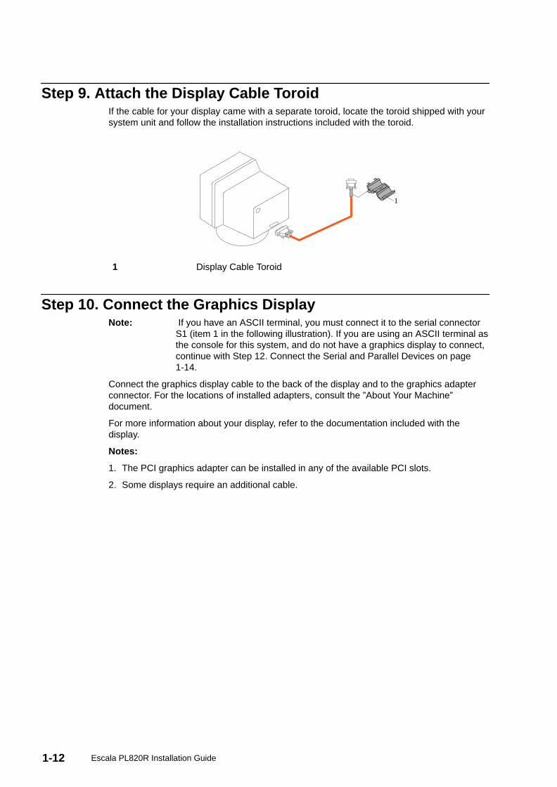
Step 9. Attach the Display Cable ToroidIf the cable for your display came with a separate toroid, locate the toroid shipped with yoursystem unit and follow the installation instructions included with the toroid.
1
1 Display Cable Toroid
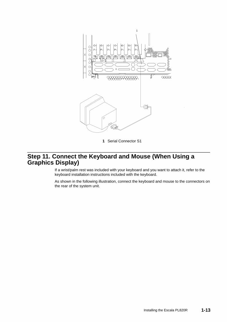
Step 10. Connect the Graphics DisplayNote: If you have an ASCII terminal, you must connect it to the serial connector
S1 (item 1 in the following illustration). If you are using an ASCII terminal asthe console for this system, and do not have a graphics display to connect,continue with Step 12. Connect the Serial and Parallel Devices on page1-14.
Connect the graphics display cable to the back of the display and to the graphics adapterconnector. For the locations of installed adapters, consult the ”About Your Machine”document.
For more information about your display, refer to the documentation included with thedisplay.
Notes:
1. The PCI graphics adapter can be installed in any of the available PCI slots.
2. Some displays require an additional cable.
1-13Installing the Escala PL820R
1
1 Serial Connector S1
Step 11. Connect the Keyboard and Mouse (When Using aGraphics Display)
If a wrist/palm rest was included with your keyboard and you want to attach it, refer to thekeyboard installation instructions included with the keyboard.
As shown in the following illustration, connect the keyboard and mouse to the connectors onthe rear of the system unit.
1-14 Escala PL820R Installation Guide
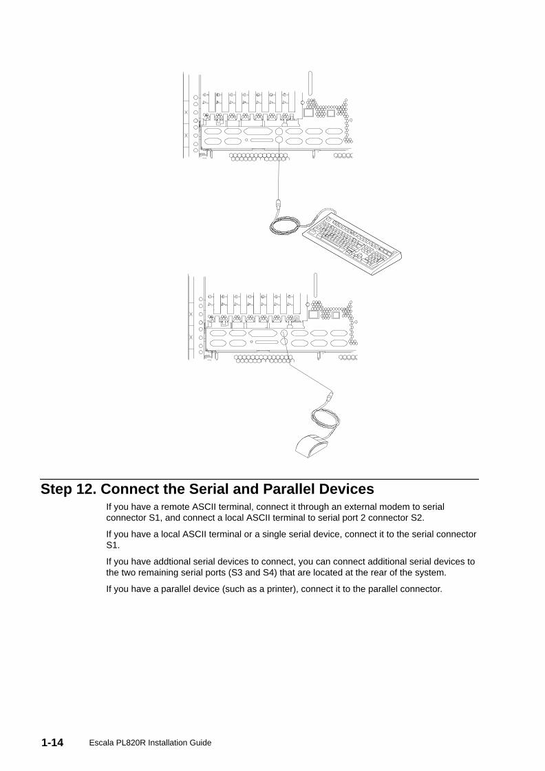
Step 12. Connect the Serial and Parallel DevicesIf you have a remote ASCII terminal, connect it through an external modem to serialconnector S1, and connect a local ASCII terminal to serial port 2 connector S2.
If you have a local ASCII terminal or a single serial device, connect it to the serial connectorS1.
If you have addtional serial devices to connect, you can connect additional serial devices tothe two remaining serial ports (S3 and S4) that are located at the rear of the system.
If you have a parallel device (such as a printer), connect it to the parallel connector.
1-15Installing the Escala PL820R
1 3 42
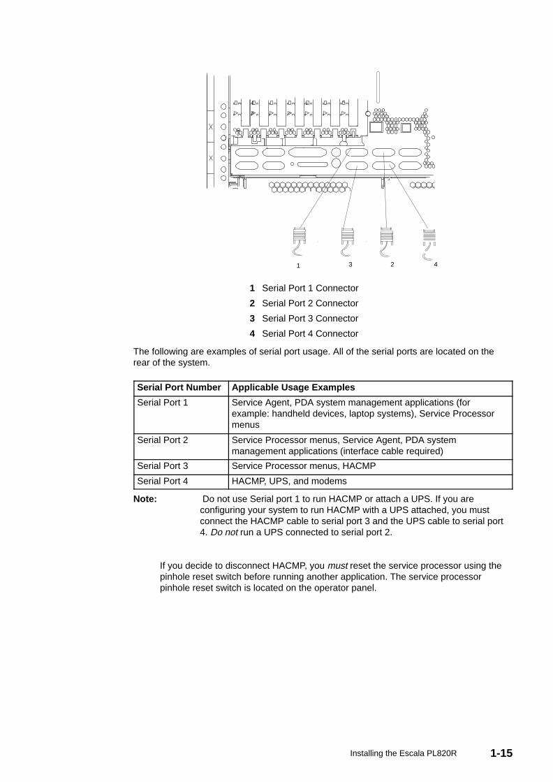
1 Serial Port 1 Connector
2 Serial Port 2 Connector
3 Serial Port 3 Connector
4 Serial Port 4 Connector
The following are examples of serial port usage. All of the serial ports are located on therear of the system.
Serial Port Number Applicable Usage Examples
Serial Port 1 Service Agent, PDA system management applications (forexample: handheld devices, laptop systems), Service Processormenus
Serial Port 2 Service Processor menus, Service Agent, PDA systemmanagement applications (interface cable required)
Serial Port 3 Service Processor menus, HACMP
Serial Port 4 HACMP, UPS, and modems
Note: Do not use Serial port 1 to run HACMP or attach a UPS. If you areconfiguring your system to run HACMP with a UPS attached, you mustconnect the HACMP cable to serial port 3 and the UPS cable to serial port4. Do not run a UPS connected to serial port 2.
If you decide to disconnect HACMP, you must reset the service processor using thepinhole reset switch before running another application. The service processorpinhole reset switch is located on the operator panel.
1-16 Escala PL820R Installation Guide
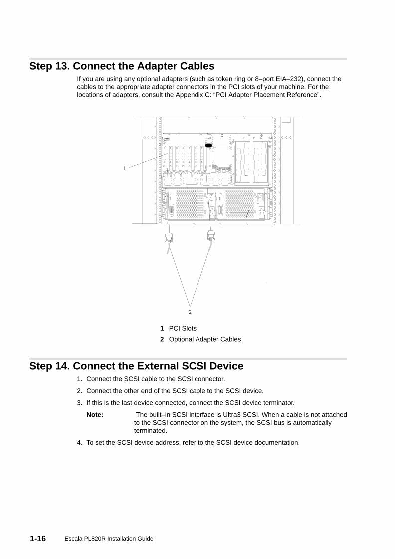
Step 13. Connect the Adapter CablesIf you are using any optional adapters (such as token ring or 8–port EIA–232), connect thecables to the appropriate adapter connectors in the PCI slots of your machine. For thelocations of adapters, consult the Appendix C: “PCI Adapter Placement Reference”.
1
2
1 PCI Slots
2 Optional Adapter Cables
Step 14. Connect the External SCSI Device1. Connect the SCSI cable to the SCSI connector.
2. Connect the other end of the SCSI cable to the SCSI device.
3. If this is the last device connected, connect the SCSI device terminator.
Note: The built–in SCSI interface is Ultra3 SCSI. When a cable is not attachedto the SCSI connector on the system, the SCSI bus is automaticallyterminated.
4. To set the SCSI device address, refer to the SCSI device documentation.
1-17Installing the Escala PL820R
4 1
23
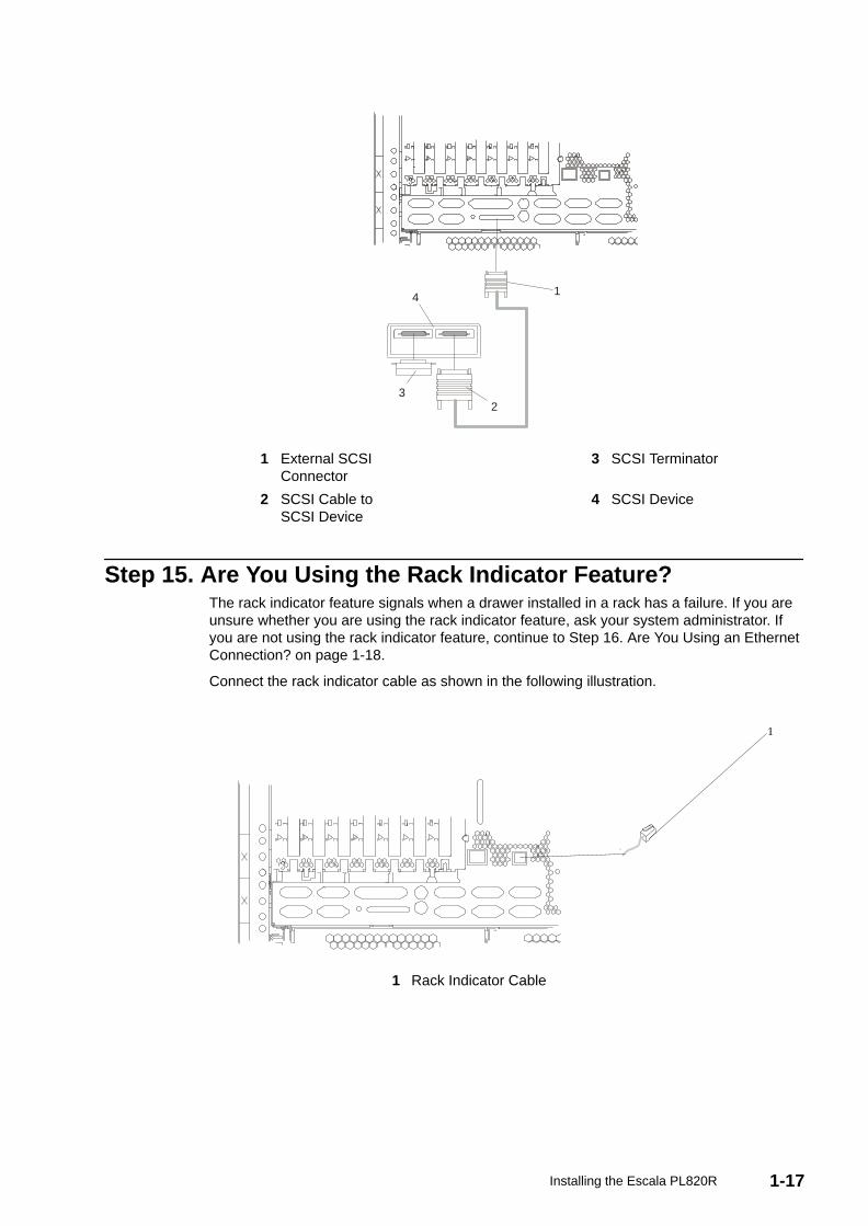
1 External SCSIConnector
3 SCSI Terminator
2 SCSI Cable toSCSI Device
4 SCSI Device
Step 15. Are You Using the Rack Indicator Feature?The rack indicator feature signals when a drawer installed in a rack has a failure. If you areunsure whether you are using the rack indicator feature, ask your system administrator. Ifyou are not using the rack indicator feature, continue to Step 16. Are You Using an EthernetConnection? on page 1-18.
Connect the rack indicator cable as shown in the following illustration.
1
1 Rack Indicator Cable
1-18 Escala PL820R Installation Guide
Step 16. Are You Using an Ethernet Connection?If you are unsure whether you are using an Ethernet connection, ask the systemadministrator. If you are not using Ethernet or you have already connected your Ethernet toan adapter, continue to Step 17. Connect the Power Cords to the Server on page 1-18.
To connect the Ethernet cable, do the following:
Note: The twisted–pair connector is compatible with the IEEE 802.3 Ethernetnetwork 10/100 Base T link.
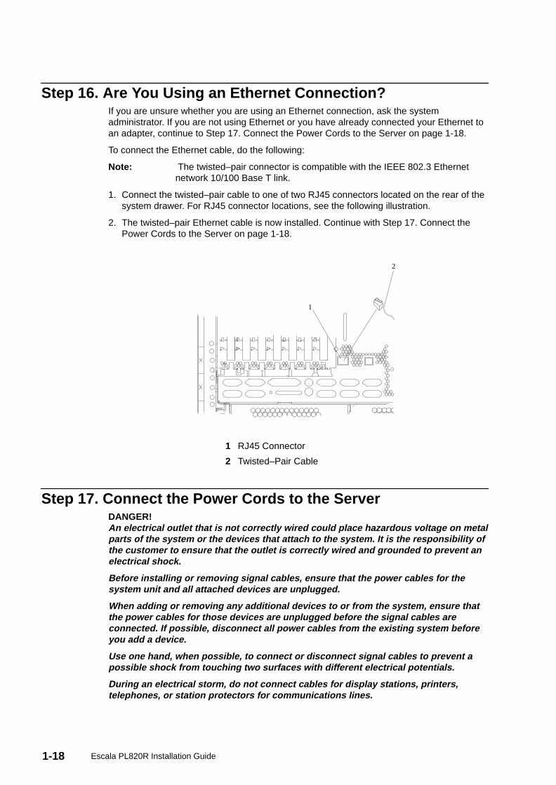
1. Connect the twisted–pair cable to one of two RJ45 connectors located on the rear of thesystem drawer. For RJ45 connector locations, see the following illustration.
2. The twisted–pair Ethernet cable is now installed. Continue with Step 17. Connect thePower Cords to the Server on page 1-18.
1
2
1 RJ45 Connector
2 Twisted–Pair Cable
Step 17. Connect the Power Cords to the ServerDANGER!An electrical outlet that is not correctly wired could place hazardous voltage on metalparts of the system or the devices that attach to the system. It is the responsibility ofthe customer to ensure that the outlet is correctly wired and grounded to prevent anelectrical shock.
Before installing or removing signal cables, ensure that the power cables for thesystem unit and all attached devices are unplugged.
When adding or removing any additional devices to or from the system, ensure thatthe power cables for those devices are unplugged before the signal cables areconnected. If possible, disconnect all power cables from the existing system beforeyou add a device.
Use one hand, when possible, to connect or disconnect signal cables to prevent apossible shock from touching two surfaces with different electrical potentials.
During an electrical storm, do not connect cables for display stations, printers,telephones, or station protectors for communications lines.
1-19Installing the Escala PL820R
Caution:This product is equipped with a three–wire power cable and plug for the user’ssafety. Use this power cable with a properly grounded electrical outlet to avoidelectrical shock.
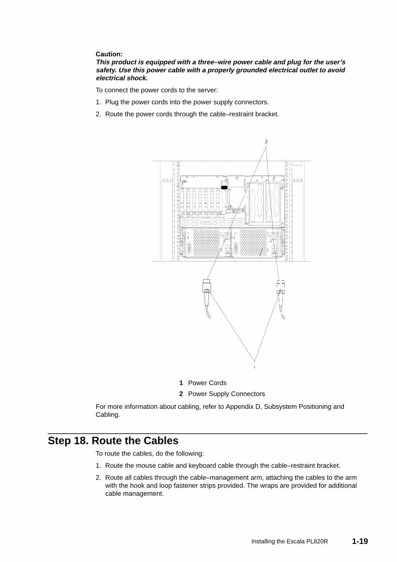
To connect the power cords to the server:
1. Plug the power cords into the power supply connectors.
2. Route the power cords through the cable–restraint bracket.
1
2
1 Power Cords
2 Power Supply Connectors
For more information about cabling, refer to Appendix D, Subsystem Positioning andCabling.
Step 18. Route the CablesTo route the cables, do the following:
1. Route the mouse cable and keyboard cable through the cable–restraint bracket.
2. Route all cables through the cable–management arm, attaching the cables to the armwith the hook and loop fastener strips provided. The wraps are provided for additionalcable management.
1-20 Escala PL820R Installation Guide
Step 19. Connect the Power CordsPlug the power cords for the system unit, display, and attached devices into electricaloutlets.
If redundant power is required, ensure that there are at least two type–7 power distributionbuses (PDBs) installed in the rack. These PDBs must be connected to two separate acpower sources. To ensure adequate power, the ESCALA PL 820R must be connected totype–7 PDBs.
Note: For information about connecting power cables to the PDUs in the rack, refer to theT00 and T42 Racks Installation and Service Guide, order number 86 A1 94KX, andto the Site Preparation Guide for Rack Suystems, order number 86 A1 30PX.
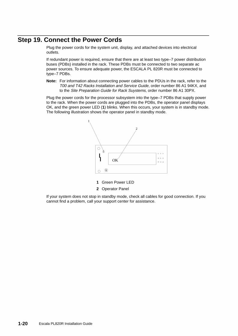
Plug the power cords for the processor subsystem into the type–7 PDBs that supply powerto the rack. When the power cords are plugged into the PDBs, the operator panel displaysOK, and the green power LED (1) blinks. When this occurs, your system is in standby mode.The following illustration shows the operator panel in standby mode.
R
1
OK
1
2
1 Green Power LED
2 Operator Panel
If your system does not stop in standby mode, check all cables for good connection. If youcannot find a problem, call your support center for assistance.

1-21Installing the Escala PL820R
Step 20. What is the Next Step?The next step in the installation procedure is to apply power to the system and verify thatthe system is ready to be used for regular operations. The steps to verify the system varydepending on how the customer has decided to manage the system. The system could bemanaged using an HMC or a directly–connected console (such as a TTY terminal or agraphics display, keyboard, and mouse).
Determine the console configuration and operating system usage for the system that youare installing. Then, using the following table, go to the appropriate checklist indicated.
If your system consoletype and power control is:
And your system usage is: Then go to:
An ASCII terminal isconnected to a serial port asthe system console. Thepower is controlled at theoperator panel.
The system is running onecopy of the operatingsystem (no partitions).
TTY Terminal Console andthe System is NotPartitioned on page 3-1.
A graphics display,keyboard, and mouse areconnected as the systemconsole. The power iscontrolled at the operatorpanel.
The system is running onecopy of the operatingsystem (no partitions).
Graphics Terminal Consoleand the System is NotPartitioned on page 3-2.
An HMC is used to managea full system partition. Thepower is controlled by theHMC.
The operating system isrunning in a full systempartition.
HMC–Managed SystemUsing a Single Full SystemPartition on page 3-3.
An HMC is used to managemultiple logical partitions.The power is controlled bythe HMC.
Multiple operating systemsare running in multiplelogical partitions.
HMC–Managed Systemwith Multiple Partitions onpage 3-5.

1-22 Escala PL820R Installation Guide
2-1Verifying the Hardware Operation
Chapter 2. Verifying the Hardware Operation
To check the system for correct hardware operation, use the system verification procedurediscussed in this chapter.
Considerations Before Running This ProcedureThese verification procedures use either online AIX diagnostics or standalone AIXdiagnostics. Either the online AIX diagnostics or the standalone AIX diagnostics must beavailable to perform this procedure. Read the following before using this procedure:
• If this system unit is directly attached to another system unit or attached to a network, besure communications with the other systems are stopped.
• This procedure requires use of all of the system resources. No other activity can berunning on the system while you are performing this procedure.
• This procedure requires a Hardware Management Console (HMC), a display attached toa graphics adapter, or an ASCII terminal attached to the S1 or S2 port.
Note: If you use a virtual terminal on the HMC and you are asked to define theterminal type, the virtual terminal is considered a VT320.
• If your system is set up to run in a partitioned configuration, this procedure runs the AIXonline diagnostics in service mode with the system booted to full system partition mode.For information about full system partition mode, refer to Full System Partition on page2-2.
Does the system have online AIX diagnostics preinstalled?
YES If there is an HMC attached to the system, go to Using the HMC to Loadthe Online Diagnostics in Service Mode on page 2-4.
If an HMC is not attached to the system, go to Loading the Online Diagnostics on aSystem without an HMC Attached on page 2-5.
NO If there is an HMC attached to the system, go to Using the HMC to Loadthe Standalone Diagnostics from CD–ROM on page 2-4.
If an HMC is not attached to the system, go to Loading the Standalone Diagnosticson a System without an HMC Attached on page 2-5.
Power ProceduresThese power procedures are here for reference during the system verification tests. Do notperform any power procedures until the verification procedures instruct you to do so.
You can power–on the ESCALA PL 820R by using the Hardware Management Console orby using the power–on button on the processor subsystem operator panel. If an HMC isconnected to the system, the HMC power–on method is the preferred method. Choose theappropriate power–on method for your system and perform the procedures to power on(start) your system.
2-2 Escala PL820R Installation Guide
HMC Power–On MethodTo power on the managed system using the HMC, you must be a member of one of thefollowing roles:
• System Administrator
• Advanced Operator
• Operator
• Service Representative
To power on the managed system, do the following:
1. In the Navigation area, click the Partition Management icon.
2. In the Contents area, select the managed system.
3. In the menu, click Selected .
4. Select Power On .
You are asked to select a power–on mode from the following:
– Partition Standby
– Full System Partition
– System Profile
The next section discusses each of these power–on modes.
Note: You must power off your managed system to switch between using the fullsystem partition and using either logical or affinity partitions. You must alsopower off the system between using logical partitions and affinity partitions.
Partition StandbyThe Partition Standby power–on option allows you to create and activate logical partitions.When the Partition Standby power–on is completed, the operator panel on the managedsystem displays LPAR..., indicating the managed system is ready for you to use the HMC topartition its resources.
Note: The full system partition is listed as Not Available because the managedsystem was powered on using the Partition Standby option.
Full System PartitionThe full system partition power–on option allows you to use all of the system’s resources onone operating system after the system has been powered on. This is the traditionalsingle–system method of using your system’s resources.
The physical operator panel on your managed system displays progress codes when youboot the system to this mode.
Power On OptionsIf you select the full system partition option, you can then select one of the following profiles:
Power On NormalThis profile boots an operating system from the designated boot device.
Power On SMS This profile is similar to Power On Diagnostic Stored Boot List Profile,except the system boots using the default boot list that is stored in thesystem firmware.
Power On Diagnostic Stored Boot ListThis profile causes the system to perform a service mode boot using theservice mode boot list saved on the managed system. If the system bootsAIX from the disk drive and AIX diagnostics are loaded on the disk drive,AIX boots to the diagnostics menu.

2-3Verifying the Hardware Operation
Using this profile to boot the system is the preferred way to run online diagnostics.
Power On Diagnostic Default Boot ListThis profile boots to the System Management Services (SMS) menus. TheSMS menus include:
– Password Utilities
– Display Error Log
– Remote Initial Program Load Setup
– SCSI Utilities
– Select Console
– MultiBoot
– Select Language
– OK Prompt
Power On Open Firmware OK PromptThis profile is used only by service representatives to obtain additionaldebug information. When this selection is enabled, the system boots to theopen firmware prompt.
To learn more about these power–on options, see the Hardware Management ConsoleInstallation and Operations Guide.
System ProfilesThe System Profile option powers on the system according to a predefined set of profiles.
Note: The profiles are activated in the order in which they are shown in thesystem profile.
Configuring the Network Using the HMCTo to complete the installation, the following configuration tasks must be performed:
• Configuring Inventory Scout Services
• Configuring Service Agent
• Collecting Vital Product Data (VPD)
• Transmitting VPD
For more information about performing these tasks, refer to the Hardware ManagementConsole Installation and Operations Guide.
Operator Panel Power–On MethodPerform the following steps to power on the processor subsystem and attached I/Osubsystems using the power button on the operator panel.
1. Open the rack door. Look for OK in the operator panel display, which indicates that thesystem is in standby.
2. Press the power button on the operator panel.
The power LED on the operator panel starts blinking at a fast rate. 9xxx checkpoints appearin the operator panel display.
When the power–on sequence is complete, the following events have occurred:
• The power LED on the system operator panel stops blinking and stays on.
• The power LEDs on the I/O subsystem come on and stay on.
2-4 Escala PL820R Installation Guide
Using the HMC to Load the Online Diagnostics in ServiceMode
To run the online diagnostics in service mode from the boot hard disk, do the following:
1. Select Server and Partition .
2. Select Partition Management .
For more information about full system partitions, refer to the Hardware ManagementConsole Installation and Operations Guide, order number 86 A1 83EF.
3. From the HMC, select Server Management .
4. In the Contents area, select the icon that represents the ESCALA PL 820R. Right–clickon the mouse, and select Open Terminal Window .
5. From the Service Processor menu on the VTERM, select Option 2 System PowerControl .
6. Select option 6. Verify that the state changes to currently disabled . Disabling fastsystem boot automatically enables slow boot.
7. Select Option 98 to exit the system power control menu.
8. Use the HMC to power on the managed system in full system partition mode by selectingthe managed system in the Contents area.
9. Highlight the desired system by right–clicking on or selecting the system in the Contentsarea. On the menu, choose Selected .
10.Select Power On .
11.Select the Power on Diagnostics Stored Boot List option.
12.Ensure that the media subsystem contains no media devices.
13.Enter any passwords, if requested.
Note: If you are unable to load the diagnostics to the point when theDIAGNOSTIC OPERATING INSTRUCTIONS display, go to Using theHMC to Load the Standalone Diagnostics from CD–ROM on page 2-4 .
Go to Running System Verification on page 2-8.
Using the HMC to Load the Standalone Diagnostics fromCD–ROM
To run the standalone diagnostics in service mode from CD–ROM, use the following steps:
1. Stop all programs, including the operating system (get help if needed).
2. Remove all tapes, diskettes, and CD–ROMs.
3. Power off the ESCALA PL 820R (refer to the Hardware Management ConsoleInstallation and Operations Guide, order number 86 A1 83EF, for more information).
4. In your desktop area, right–click on the mouse, and select Open Terminal Window .
5. From the service processor menu on the VTERM, select option 2, System PowerControl Menu .
6. Select option 6. Verify that the state changes to currently disabled . Disabling fastsystem boot automatically enables slow boot.
7. Select option 98 to exit the system power control menu.
2-5Verifying the Hardware Operation
8. Use the HMC to power on the managed server in full system partition mode. SelectPower on Diagnostic Default Boot List .
9. Insert the CD–ROM into the CD–ROM drive in the media bay in the ESCALA PL 820R(not into the HMC CD–ROM drive).
Go to Running System Verification on page 2-8.
Note: If you are unable to load standalone diagnostics, call your support centerfor assistance.
Loading the Online Diagnostics on a System without an HMCAttached
To run the online diagnostics in service mode from the boot hard disk, do the following:
1. Stop all programs including the operating system (get help if needed).
2. Remove all tapes, diskettes, and CD–ROM discs.
3. Turn off the system unit power.
4. Turn on the system unit power.
5. After the keyboard POST indicator displays on the firmware console and before the lastPOST indicator (speaker ) displays, press the numeric 6 key on either the directlyattached keyboard or the ASCII terminal to indicate that a service mode boot should beinitiated using the customized service mode boot list.
6. Enter any requested password.
Note: If you are unable to load the diagnostics to the point when theDIAGNOSTIC OPERATING INSTRUCTIONS display, call your supportcenter for assistance.
Loading the Standalone Diagnostics on a System without anHMC Attached
To run the standalone diagnostics in service mode from the boot hard disk, do the following:
Note: Online diagnostics are not available when the operating system is Linux.
1. Stop all programs including the operating system (get help if needed).
2. Remove all tapes, diskettes, and CD–ROM discs.
3. Turn off the system unit power.
4. Turn on the system unit power and immediately insert the diagnostic CD–ROM into theCD–ROM drive.
5. After the keyboard POST indicator displays on the firmware console and before the lastPOST indicator (speaker ) displays, press the numeric 5 key on either the directlyattached keyboard or the ASCII terminal to indicate that a service mode boot should beinitiated using the default service mode boot list.
6. Enter any requested password.
Note: If you are unable to load the diagnostics to the point when theDIAGNOSTIC OPERATING INSTRUCTIONS display, call your supportcenter for assistance.
2-6 Escala PL820R Installation Guide
Running Standalone Diagnostics from a Network InstallationManagement (NIM) Server with an HMC Attached to the System
A client system connected to a network with a Network Installation Management (NIM)server can boot standalone diagnostics from the NIM server if the client–specific settings onboth the NIM server and client are correct.
Notes:
1. All operations to configure the NIM server require root user authority.
2. If you replace the network adapter in the client, the network–adapter hardware–addresssettings for the client must be updated on the NIM server.
3. The Cstate for each standalone diagnostics client on the NIM server should be kept inthe diagnostic boot has been enabled state.
4. On the client system, the NIM server network adapter should be put in the bootlist afterthe boot disk drive. This allows the system to boot in standalone diagnostics from theNIM server if there is a problem booting from the disk drive. For information about settingthe bootlist, see the Multiboot section under ”SMS” in the client system’s service guide.
NIM Server ConfigurationRefer to the ”Advanced NIM Configuration Tasks” chapter of the AIX 5L Installation Guideand Reference, order number SC23–4389, for information on doing the following:
• Registering a client on the NIM server
• Enabling a client to run diagnostics from the NIM server
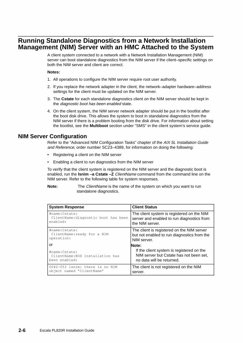
To verify that the client system is registered on the NIM server and the diagnostic boot isenabled, run the lsnim –a Cstate –Z ClientName command from the command line on theNIM server. Refer to the following table for system responses.
Note: The ClientName is the name of the system on which you want to runstandalone diagnostics.
System Response Client Status
#name:Cstate: ClientName:diagnostic boot has beenenabled:
The client system is registered on the NIMserver and enabled to run diagnostics fromthe NIM server.
#name:Cstate: ClientName:ready for a NIMoperation:
or
#name:Cstate: ClientName:BOS installation hasbeen enabled:
The client is registered on the NIM serverbut not enabled to run diagnostics from theNIM server.
Note:If the client system is registered on theNIM server but Cstate has not been set,no data will be returned.
0042–053 lsnim: there is no NIMobject named ”ClientName”
The client is not registered on the NIMserver.
2-7Verifying the Hardware Operation
Client Configuration and Booting Standalone Diagnostics from the NIMServer
To run standalone diagnostics on a client from the NIM server, do the following:
1. Remove any removable media (tape or CD–ROM disc).
2. Stop all programs including the operating system (get help if needed).
3. If you are running standalone diagnostics in a full system partition, verify with the systemadministrator and system users that the system unit can shut down. Stop all programs,including the operating system. Refer to the operating system documentation forshutdown command information.
In a partitioned system, make the CD–ROM drive available to the partition used to runstandalone diagnostics (refer to the Hardware Management Console Installation andOperations Guide for more information). Verify with the system administrator and systemusers using that partition that all applications on that partition must be stopped, and thatthe partition will be rebooted. Stop all programs on that partition, including the operatingsystem.
4. If you are in a full system partition, power on the system unit to run standalonediagnostics. In a partitioned system, reboot the partition to run standalone diagnostics.
5. When the keyboard indicator is displayed (the word keyboard ), press the number 1 keyon the keyboard to display the SMS menu.
6. Enter any requested passwords.
7. Select Setup Remote IPL (Initial Program Load) .
8. Enter the client address, server address, gateway address (if applicable), and subnetmask. Exit to the Network Parameters screen.
9. If the NIM server is set up to allow pinging from the client system, use the ping utility inthe RIPL utility to verify that the client system can ping the NIM server. Under the pingutility, choose the network adapter that provides the attachment to the NIM server to dothe ping operation. If the ping returns with an OK prompt, the client is prepared to bootfrom the NIM server. If ping returns with a FAILED prompt, the client cannot proceedwith the NIM boot.
To do a one–time boot of the network adapter attached to the NIM server network, do thefollowing:
1. Exit to the SMS Main screen.
2. Select Select Boot Options .
3. Select Install or Boot a Device .
4. On the Select Device Type screen, select Network .
5. Set the network parameters for the adapter from which you want to boot.
6. Exit completely from SMS. The system starts loading packets while doing a bootp fromthe network.
Follow the instructions on the screen to select the system console.
• If Diagnostics Operating Instructions Version x.x.x displays,standalone diagnostics have loaded successfully.
• If the operating system login prompt displays, standalone diagnostics did not load. Checkthe following items:
– The network parameters on the client may be incorrect.
– Cstate on the NIM server may be incorrect.
– Network problems might be preventing you from connecting to the NIM server.

2-8 Escala PL820R Installation Guide
Running System VerificationWhen the Diagnostic Operating Instructions display, do the following to run systemverification:
1. Press Enter.
2. If the terminal type is requested, you must use the Initialize Terminal option on theFunction Selection menu to initialize the operating system before you can continue withthe diagnostics.
Note: If you use a virtual terminal on the HMC and you are asked to define theterminal type, the virtual terminal is considered a VT320.
3. Select the System Verification option on the Diagnostic Mode Selection menu.
4. To run a general checkout of all installed resources, select the All Resource option onthe Diagnostic Selection menu. Follow the instructions on the screen to complete thecheckout procedure.
To check one particular resource, select that resource on the Diagnostic Selection menu.
The checkout program ends with either of the following results:
• The Testing Complete screen displays a message stating No trouble was found .
• The A Problem Was Detected On (Time Stamp) menu displays, with either a servicerequest number (SRN) or an error code. Make a note of any codes displayed on thedisplay or operator panel.
To perform additional system verification, go to Performing Additional System Verification onpage 2-8. To exit diagnostics, go to Stopping the Diagnostics.
Performing Additional System VerificationTo perform additional system verification, do the following:
1. Press Enter to return to the Diagnostic Selection menu.
2. To check other resources, select the resource. When you have checked all of theresources you need to check, go to Stopping the Diagnostics on page 2-8.
Stopping the DiagnosticsTo stop the diagnostics, do the following:
1. To exit the diagnostics, press the F3 key (from a defined terminal) or press 99 (from anundefined terminal).
2. If you changed any attributes on your terminal to run the diagnostics, change the settingsback to normal.
3. This completes the system verification.
If the server passed all the diagnostic tests, the verification process is complete and yourserver is ready to use.
If you received an error code, record the code and go to the ESCALA PL 820R ServiceGuide.
2-9Verifying the Hardware Operation
Verify that the Latest Firmware and Adapter and DriveMicrocode are Installed
Use the procedures in this section to verify that the latest firmware and adapter microcodeare installed on the system. The firmware and microcode are available from your marketingrepresentitive.
Verify that the Latest HMC Software is InstalledUse the following instructions to verify the software level of the HMC that is managing thesystem you just installed.
1. Determine the level of the HMC software running on the HMC. If you don’t know the levelof your HMC’s software, refer to the section entitled ”Updating the HMC Software” in theHardware Management Console Installation and Operations Guide, order number 86 A183EF.
2. Go to the following Web site for the latest HMC corrective service software:http://techsupport.services.ibm.com/server/hmc/corrsrv.html. If the level of software onyour HMC is not at the same level as the version on the Web, download and update theHMC software to the latest level. Instructions for updating the HMC software can befound in the Hardware Management Console Installation and Operations Guide, ordernumber 86 A1 83EF.
Verify Partition Standby and Full System Partition PowerOptions
If an HMC is attached, perform these procedures to verify that the system can be booted topartition–standby and full–system partition modes. Perform this procedure just before youturn the system over to the customer.
1. At the HMC, in the Navigation area, click the Partition Management icon.
2. In the Contents area, select the managed system.
3. In the menu, click Selected .
4. Select Power On .
You are asked to select a power–on mode from the following:
– Partition Standby
– Full System Partition
– System Profile
5. In the Power On Options menu, select Partition Standby and click OK.
6. If the boot to Partition Standby is successful, LPAR will appear in the operator panel.
7. Reboot the system to Full System Partition.
8. If the boot to Partition Standby and the boot to Full System Partition operations are notsuccessful, follow normal service procedures to correct the problem.
2-10 Escala PL820R Installation Guide
Final Installation TasksThis section contains information on completing the installation of the ESCALA PL 820R.
Complete System Records and Installation ProcedureUpdate the ”System Records” in Appendix G, System Records on page G-1 to reflect theconfiguration of the system adapters and devices that are installed. After completing therecords, deliver this book to the system administrator. The system administrator canproceed with installing and configuring the operating system.
Configure the NetworkTo configure the network, the following tasks must be performed:
• Configuring Inventory Scout
• Collecting Vital Product Data (VPD)
• Configuring Service Agent
For more information on performing these tasks, refer to the Hardware ManagementConsole Installation and Operations Guide.
3-1Completing the Installation
Chapter 3. Completing the Installation
This chapter contains information on how to ensure that the installation is complete and youare ready to turn the system over to the system administrator. Complete the steps describedin this chapter after you verify the hardware operation as described in Verifying theHardware Operation on page 2-1.
Step 1. Bezels and DoorsIf you have not done so, install any remaining bezels and close the doors on the rack.
Step 2. Complete Installation ChecklistsThe installation instructions prompt you through the installation procedure. Use the checklistas you work to ensure that the installation process is complete.
Note: The procedures referenced in this section might be optional on yoursystem. Contact your service support representative for more information.
TTY Terminal Console and the System is Not PartitionedTo complete an installation when the TTY terminal is used for the system console, theinstaller must:
__ 1. Locate the installed TTY terminal. Refer to Step 7. Check Your Display orConsole Type on page 1-11.
__ 2. Check the connection of the TTY terminal to the appropriate serial port on thesystem unit. Refer to Step 12. Connect the Serial and Parallel Devices onpage 1-14.
__ 3. Arrange the system console and attached devices so that they can be usedcomfortably. Refer to Step 6. Position the Display on page 1-10.
__ 4. Connect the power to the system. Refer to Step 17. Connect the Power Cordsto the Server on page 1-18.
__ 5. Verify the system operation by completing the procedures in Verifying theHardware Operation on page 2-1.
__ 6. Verify that the latest firmware and adapter/drive microcode code are installed.Refer to Verify that the Latest Firmware and Adapter and Drive Microcode areInstalled on page 2-9.
3-2 Escala PL820R Installation Guide
__ 7. Ensure that the operating system is installed:
If an operating system has been preinstalled in your system, go to the nextstep.
If you plan to install the operating system now, see the installation instructionsprovided with the operating system.
• The operating system can be installed from a CD (if a CD–ROM drive isinstalled). For this method, the system must have a CD–ROM drive.
• The operating system can be installed from a Network InstallationManagement (NIM) server. For information about installing AIX from a NIMserver, see the AIX 5L Installation Guide and Reference, order number 86A2 07EG.
__ 8. If the system is not running, start the system. Refer to the procedures inOperator Panel Power–On Method on page 2-3.
__ 9. If you want to set up your service processor, perform the followingprocedures:
a. Configure Inventory Scout Services and Service Agent.
b. Collect vital product data.
c. Transmit vital product data.
For more information about performing these tasks, refer to user’s guide foryour system.
__ 10. Leave this installation guide with the system administrator.
Graphics Terminal Console and the System is Not PartitionedTo complete an installation when a graphics display, keyboard, and mouse are used for thesystem console, the installer must:
__ 1. Locate the installed graphics display, keyboard, and mouse. Refer to Step 7.Check Your Display or Console Type on page 1-11
__ 2. Check the connection of the graphics display to the appropriate PCI adapter,and the connection of the keyboard and mouse to the system unit. Refer toStep 10. Connect the Graphics Display on page 1-12.
__ 3. Arrange the system console and attached devices so that they can be usedcomfortably. Refer to Step 6. Position the Display on page 1-10.
__ 4. Connect the power to the system. Refer to Step 17. Connect the Power Cordsto the Server on page 1-18.
__ 5. Verify the system operation by completing the procedures in Verifying theHardware Operation on page 2-1.
3-3Completing the Installation
__ 6. Verify that the latest firmware and adapter/drive microcode code are installed.Refer to Verify that the Latest Firmware and Adapter and Drive Microcode areInstalled on page 2-9.
__ 7. Ensure that the operating system is installed:
If an operating system has been preinstalled in your system, go to the nextstep.
If you plan to install the operating system now, see the installation instructionsprovided with the operating system.
• The operating system can be installed from a CD (if a CD–ROM drive isinstalled). For this method, the system must have a CD–ROM drive.
• The operating system can be installed from a Network InstallationManagement (NIM) server. For information about installing AIX from a NIMserver, see the AIX 5L Installation Guide and Reference, order number 86A2 07EG.
__ 8. If the system is not running, start the system. Refer to the procedures inOperator Panel Power–On Method on page 2-3.
__ 9. If you want to set up your service processor, perform the followingprocedures:
a. Configure Inventory Scout Services and Service Agent.
b. Collect vital product data.
c. Transmit vital product data.
For more information about performing these tasks, refer to user’s guide foryour system.
__ 10. Leave this installation guide with the system administrator.
HMC–Managed System Using a Single Full System PartitionTo complete an installation when an HMC is used to manage a full system partition on amanaged system, the installer must:
__ 1. Locate the installed HMC. If the HMC is not already installed, install it now.Refer to the Hardware Management Console Installation and OperationsGuide, order number 86 A1 83EF.
__ 2. Arrange the HMC and attached devices so that they can be used comfortably.Refer to the Hardware Management Console Installation and OperationsGuide, order number 86 A1 83EF.
__ 3. Ensure that the HMC is running. Refer to Hardware Management ConsoleInstallation and Operations Guide, order number 86 A1 83EF.
__ 4. Connect the power to the system. Refer to Step 17. Connect the Power Cordsto the Server on page 1-18.
3-4 Escala PL820R Installation Guide
__ 5. Verify the system operation by completing the procedures in Verifying theHardware Operation on page 2-1.
__ 6. Verify that the latest firmware and adapter/drive microcode code are installed.Refer to Verify that the Latest Firmware and Adapter and Drive Microcode areInstalled on page 2-9.
__ 7. Ensure that the operating system is installed:
If an operating system has been preinstalled in your system, go to the nextstep.
If you plan to install the operating system now, see the installation instructionsprovided with the operating system.
• The operating system can be installed from a CD (if a CD–ROM drive isinstalled). For this method, the system must have a CD–ROM drive.
• The operating system can be installed from a Network InstallationManagement (NIM) server. For information about installing AIX from a NIMserver, see the AIX 5L Installation Guide and Reference, order number 86A2 07EG.
__ 8. If the system is not running, start the system. refer to the HardwareManagement Console Installation and Operations Guide, order number 86 A183EF for procedures on starting the system from the HMC.
__ 9. Configure the network. Perform the following procedures:
a. Configure Inventory Scout Services and Service Agent.
b. Collect vital product data.
c. Transmit vital product data.
For more information about performing these tasks, refer to the HardwareManagement Console Installation and Operations Guide, order number 86 A183EF.
__ 10. Leave this installation guide with the system administrator.

3-5Completing the Installation
HMC–Managed System with Multiple PartitionsTo complete an installation when an HMC is used to manage a multi–partition system, theinstaller must:
__ 1. Locate the installed HMC. If the HMC is not already installed, install it now.Refer to the Hardware Management Console Installation and OperationsGuide, order number 86 A1 83EF.
__ 2. Arrange the HMC and attached devices so that they can be used comfortably.Refer to the Hardware Management Console Installation and OperationsGuide, order number 86 A1 83EF.
__ 3. Ensure that the HMC is running. Refer to Hardware Management ConsoleInstallation and Operations Guide, order number 86 A1 83EF.
__ 4. Connect the power to the system. Refer to Step 17. Connect the Power Cordsto the Server on page 1-18.
__ 5. Verify the system operation by completing the procedures in Verifying theHardware Operation on page 2-1.
__ 6. Verify that the latest firmware and adapter/drive microcode code are installed.Refer to Verify that the Latest Firmware and Adapter and Drive Microcode areInstalled on page 2-9.
__ 7. Ensure that the operating system is installed:
If an operating system has been preinstalled in your system, go to the nextstep.
If you plan to install the operating system now, see the installation instructionsprovided with the operating system.
• The operating system can be installed from a CD (if a CD–ROM drive isinstalled). For this method, the system must have a CD–ROM drive.
• The operating system can be installed from a Network InstallationManagement (NIM) server. For information about installing AIX from a NIMserver, see the AIX 5L Installation Guide and Reference, order number 86A2 07EG.
__ 8. If the system is not running, start the system. refer to the HardwareManagement Console Installation and Operations Guide, order number 86 A183EF for procedures on starting the system from the HMC.

3-6 Escala PL820R Installation Guide
__ 9. Configure the network. Perform the following procedures:
a. Configure Inventory Scout Services and Service Agent.
b. Collect vital product data.
c. Transmit vital product data.
For more information about performing these tasks, refer to the HardwareManagement Console Installation and Operations Guide, order number 86 A183EF.
__ 10. Leave this installation guide with the system administrator.

4-1Installing Options
Chapter 4. Installing Options for the ESCALA PL 820R
This chapter provides instructions to help you add options to your system. In case you needto remove one option to install another, some option removal instructions are provided. Ifyou have several internal options to install, these instructions enable you to add them all atone time.
Before performing any of the installation or removal procedures in this chapter, read thefollowing safety considerations.
Safety ConsiderationsObserve the following safety precautions anytime you work with this system unit.
In the system you are about to set up or service:
• The ac power interface connector is considered the main power disconnect device.
• This system has redundant power supply capabilities, meaning that it has the capabilityof having two power supplies running simultaneously in the same system unit. When youare instructed to disconnect the power source, ensure that all power cords have beenunplugged.
DANGER!An electrical outlet that is not correctly wired could place hazardous voltage onmetal parts of the system or the devices that attach to the system. It is theresponsibility of the customer to ensure that the outlet is correctly wired andgrounded to prevent an electrical shock.
Before installing or removing signal cables, ensure that the power cables forthe system unit and all attached devices are unplugged.
When adding or removing any additional devices to or from the system, ensurethat the power cables for those devices are unplugged before the signal cablesare connected. If possible, disconnect all power cables from the existingsystem before you add a device.
Use one hand, when possible, to connect or disconnect signal cables toprevent a possible shock from touching two surfaces with different electricalpotentials.
During an electrical storm, do not connect cables for display stations, printers,telephones, or station protectors for communications lines.
Caution:This product is equipped with a three–wire power cable and plug for the user’ssafety. Use this power cable with a properly grounded electrical outlet to avoidelectrical shock.
Caution:This unit has more than one power supply cord. To reduce the risk of electricalshock, disconnect two power supply cords before servicing.

4-2 Escala PL820R Installation Guide
Notes:
1. This unit will have two power cords only if the redundant power supply feature isinstalled.
2. Servicing of the ESCALA PL 820R is performed with the system in the rack and placedinto the service position. See the ESCALA PL 820R Service Guide for more informationon the service position for the ESCALA PL 820R.
3. A highlighted number in a procedure step refers to the numbered components found inthe illustration for that particular procedure.
Handling Static–Sensitive DevicesAttention: Electronic boards, diskette drives, and disk drives are sensitive to staticelectricity discharge. These devices are wrapped in antistatic bags to prevent this damage.
Take the following precautions:
• If you have an antistatic wrist strap available, use it while handling the device.
• Do not remove the device from the antistatic bag until you are ready to install the devicein the system.
• With the device still in its antistatic bag, touch it to a metal frame of the system.
• Grasp cards and boards by the edges. Hold drives by the frame. Avoid touching thesolder joints or pins.
• If you need to lay the device down while it is out of the antistatic bag, lay it on theantistatic bag. Before picking it up again, touch the antistatic bag and the metal frame ofthe system at the same time.
• Handle the devices carefully to prevent permanent damage.
Color Coded IndicatorsSome components in this system are color coded to indicate a location where an installationor removal task is performed. When you are installing or removing components in thissystem, note that the handles and latches are indicated using either blue or orange color.The colors indicate the following:
• Orange designates a location for a component that can be installed or removed withoutpowering off the system. The system hardware and operating system must be enabled toallow these tasks. Also, there might be preparatory steps that the user must performbefore any installation or removal is attempted.
• Blue indicates a touch point that is used in the installation or removal of a component.The power must be removed before you install or remove a part that has only a bluetouch point.
• If a component has both blue and orange indicators, the orange indicator takesprecedence over the blue indicator.
4-3Installing Options
Stopping the SystemAttention: If you are installing a hot–pluggable component, do not stop the system.
Is an HMC attached to the system?
YES Do the following:
1. Ask the customer to shut down all active partitions.
2. Use the HMC power–off function to power off the system.
As the system powers off, the power LED on the operator panel starts blinking at afast rate, and B0FF appears in the system operator panel display.
When the power–off sequence is complete, the system goes into standby mode, andthe following occurs:
– OK displays on the operator panel.
– The system’s operator panel power indicator LED blinks at a slow rate.
After the operating system is in standby mode, set the power switches of anyattached devices to off.
NO Do the following:
1. Ask the customer to stop all applications that are running on the system.
2. Log into the system as the root user.
3. At the command line, type shutdown to stop the operating system.
Note: If Linux is running, enter the shutdown now –h command.
As the system powers off, the power LED on the operator panel starts blinking at afast rate. B0FF appears in the operator panel display.
When the power–off sequence is complete, the system goes into standby mode andthe following occurs:
– OK displays on the operator panel.
– The system’s operator panel power indicator LED blinks at a slow rate.
After the operating system is in standby mode, set the power switches of anyattached devices to off.
Disk Drive OptionsAttention: The Linux operating system does not support some hot–pluggable procedures.Also, Linux does not support hot–plugging any hot–pluggable PCI adapters or devices. Thesystem with Linux installed on one or more partitions must be shutdown and powered offbefore replacing any PCI adapter or device assigned to a Linux partition. Please follow thenon–hot–pluggable adapter or device procedures when replacing a PCI adapter or device inany partition with Linux installed.
Your system can have up to four disk drives installed. The disk drives are mounted incarriers that allow the disk drives to plug into the bay slots. When you install or remove diskdrives, refer to the procedures in this section.
Disk drives that are installed in the four–position bays are referred to as hot–pluggable diskdrives.
The SCSI disk drive bays have light emitting diodes (LEDs) to identify the state of the diskdrive slot (1) shown in the following illustration. The disk drive carriers also have statuslights (2), which are used to determine if the drive is active.
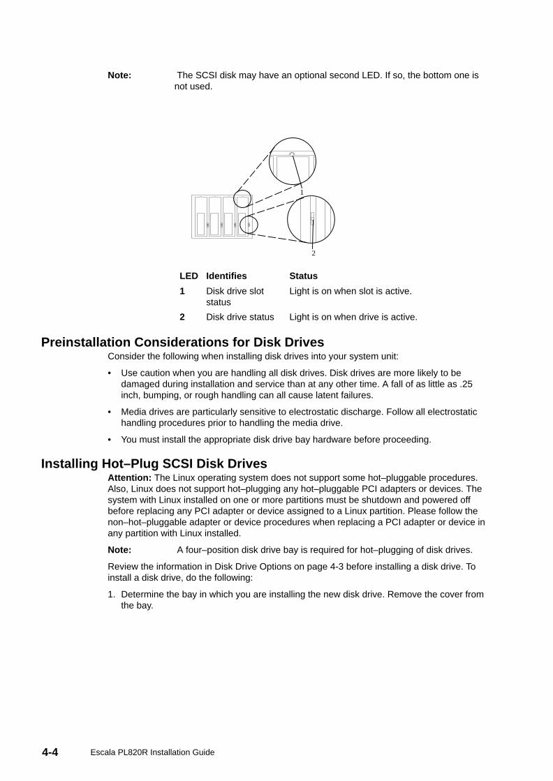
4-4 Escala PL820R Installation Guide
Note: The SCSI disk may have an optional second LED. If so, the bottom one isnot used.
1
2
LED Identifies Status
1 Disk drive slotstatus
Light is on when slot is active.
2 Disk drive status Light is on when drive is active.
Preinstallation Considerations for Disk DrivesConsider the following when installing disk drives into your system unit:
• Use caution when you are handling all disk drives. Disk drives are more likely to bedamaged during installation and service than at any other time. A fall of as little as .25inch, bumping, or rough handling can all cause latent failures.
• Media drives are particularly sensitive to electrostatic discharge. Follow all electrostatichandling procedures prior to handling the media drive.
• You must install the appropriate disk drive bay hardware before proceeding.
Installing Hot–Plug SCSI Disk DrivesAttention: The Linux operating system does not support some hot–pluggable procedures.Also, Linux does not support hot–plugging any hot–pluggable PCI adapters or devices. Thesystem with Linux installed on one or more partitions must be shutdown and powered offbefore replacing any PCI adapter or device assigned to a Linux partition. Please follow thenon–hot–pluggable adapter or device procedures when replacing a PCI adapter or device inany partition with Linux installed.
Note: A four–position disk drive bay is required for hot–plugging of disk drives.
Review the information in Disk Drive Options on page 4-3 before installing a disk drive. Toinstall a disk drive, do the following:
1. Determine the bay in which you are installing the new disk drive. Remove the cover fromthe bay.
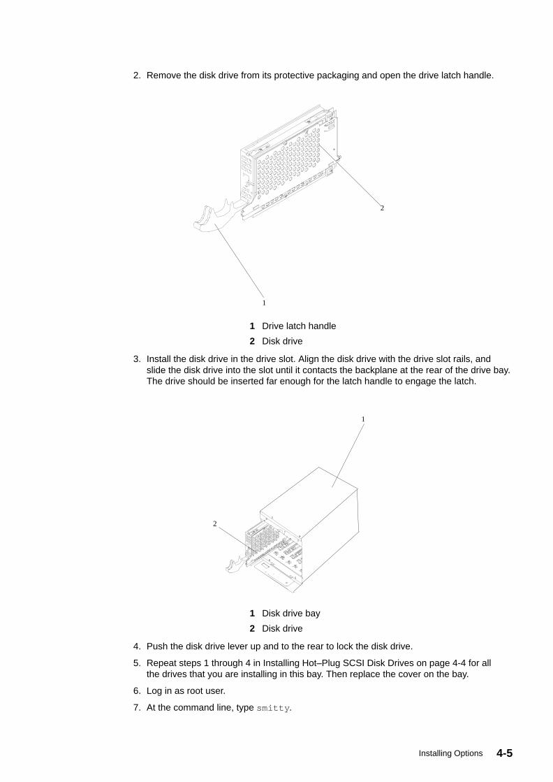
4-5Installing Options
2. Remove the disk drive from its protective packaging and open the drive latch handle.
1
2
1 Drive latch handle
2 Disk drive
3. Install the disk drive in the drive slot. Align the disk drive with the drive slot rails, andslide the disk drive into the slot until it contacts the backplane at the rear of the drive bay.The drive should be inserted far enough for the latch handle to engage the latch.
1
2
1 Disk drive bay
2 Disk drive
4. Push the disk drive lever up and to the rear to lock the disk drive.
5. Repeat steps 1 through 4 in Installing Hot–Plug SCSI Disk Drives on page 4-4 for allthe drives that you are installing in this bay. Then replace the cover on the bay.
6. Log in as root user.
7. At the command line, type smitty .
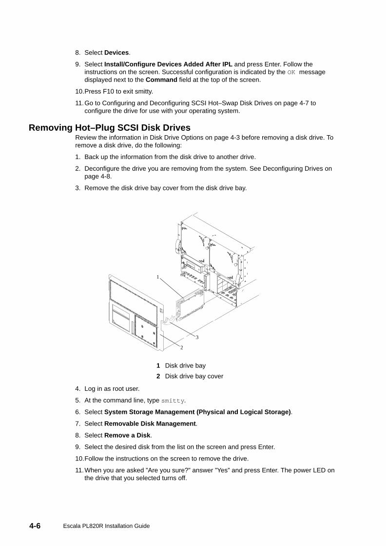
4-6 Escala PL820R Installation Guide
8. Select Devices .
9. Select Install/Configure Devices Added After IPL and press Enter. Follow theinstructions on the screen. Successful configuration is indicated by the OK messagedisplayed next to the Command field at the top of the screen.
10.Press F10 to exit smitty.
11.Go to Configuring and Deconfiguring SCSI Hot–Swap Disk Drives on page 4-7 toconfigure the drive for use with your operating system.
Removing Hot–Plug SCSI Disk DrivesReview the information in Disk Drive Options on page 4-3 before removing a disk drive. Toremove a disk drive, do the following:
1. Back up the information from the disk drive to another drive.
2. Deconfigure the drive you are removing from the system. See Deconfiguring Drives onpage 4-8.
3. Remove the disk drive bay cover from the disk drive bay.
1
2
3
1 Disk drive bay
2 Disk drive bay cover
4. Log in as root user.
5. At the command line, type smitty .
6. Select System Storage Management (Physical and Logical Storage) .
7. Select Removable Disk Management .
8. Select Remove a Disk .
9. Select the desired disk from the list on the screen and press Enter.
10.Follow the instructions on the screen to remove the drive.
11.When you are asked ”Are you sure?” answer ”Yes” and press Enter. The power LED onthe drive that you selected turns off.
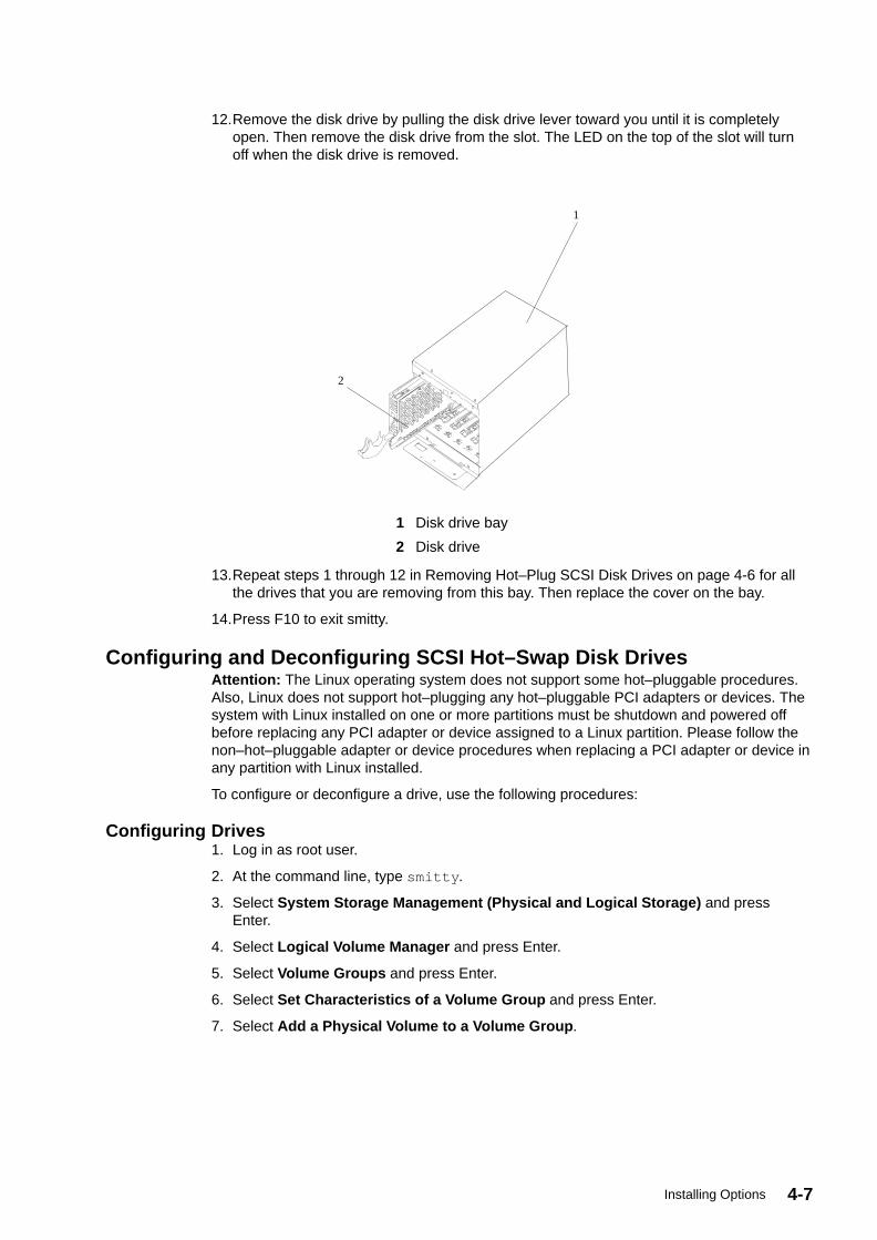
4-7Installing Options
12.Remove the disk drive by pulling the disk drive lever toward you until it is completelyopen. Then remove the disk drive from the slot. The LED on the top of the slot will turnoff when the disk drive is removed.
1
2
1 Disk drive bay
2 Disk drive
13.Repeat steps 1 through 12 in Removing Hot–Plug SCSI Disk Drives on page 4-6 for allthe drives that you are removing from this bay. Then replace the cover on the bay.
14.Press F10 to exit smitty.
Configuring and Deconfiguring SCSI Hot–Swap Disk DrivesAttention: The Linux operating system does not support some hot–pluggable procedures.Also, Linux does not support hot–plugging any hot–pluggable PCI adapters or devices. Thesystem with Linux installed on one or more partitions must be shutdown and powered offbefore replacing any PCI adapter or device assigned to a Linux partition. Please follow thenon–hot–pluggable adapter or device procedures when replacing a PCI adapter or device inany partition with Linux installed.
To configure or deconfigure a drive, use the following procedures:
Configuring Drives1. Log in as root user.
2. At the command line, type smitty .
3. Select System Storage Management (Physical and Logical Storage) and pressEnter.
4. Select Logical Volume Manager and press Enter.
5. Select Volume Groups and press Enter.
6. Select Set Characteristics of a Volume Group and press Enter.
7. Select Add a Physical Volume to a Volume Group .
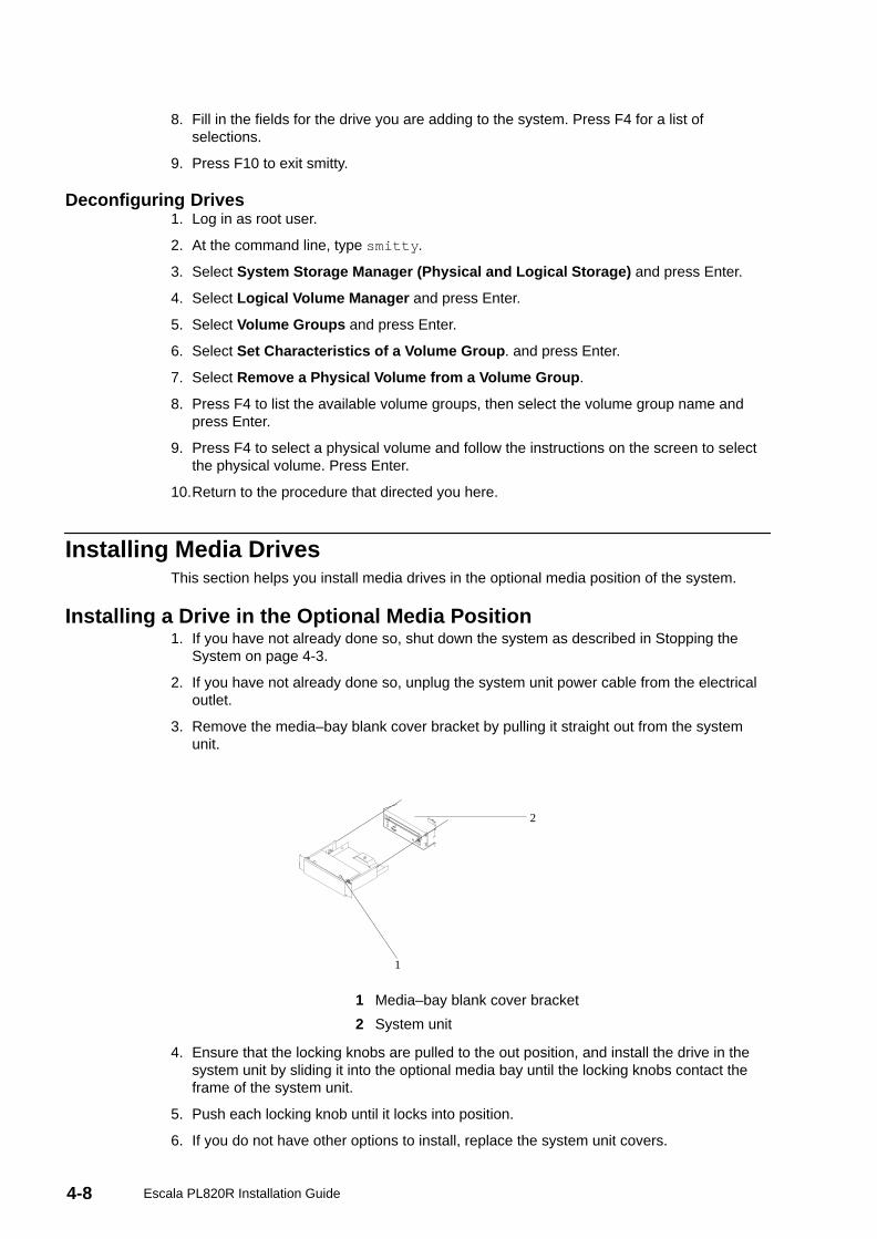
4-8 Escala PL820R Installation Guide
8. Fill in the fields for the drive you are adding to the system. Press F4 for a list ofselections.
9. Press F10 to exit smitty.
Deconfiguring Drives1. Log in as root user.
2. At the command line, type smitty .
3. Select System Storage Manager (Physical and Logical Storage) and press Enter.
4. Select Logical Volume Manager and press Enter.
5. Select Volume Groups and press Enter.
6. Select Set Characteristics of a Volume Group . and press Enter.
7. Select Remove a Physical Volume from a Volume Group .
8. Press F4 to list the available volume groups, then select the volume group name andpress Enter.
9. Press F4 to select a physical volume and follow the instructions on the screen to selectthe physical volume. Press Enter.
10.Return to the procedure that directed you here.
Installing Media DrivesThis section helps you install media drives in the optional media position of the system.
Installing a Drive in the Optional Media Position1. If you have not already done so, shut down the system as described in Stopping the
System on page 4-3.
2. If you have not already done so, unplug the system unit power cable from the electricaloutlet.
3. Remove the media–bay blank cover bracket by pulling it straight out from the systemunit.
1
2
1 Media–bay blank cover bracket
2 System unit
4. Ensure that the locking knobs are pulled to the out position, and install the drive in thesystem unit by sliding it into the optional media bay until the locking knobs contact theframe of the system unit.
5. Push each locking knob until it locks into position.
6. If you do not have other options to install, replace the system unit covers.
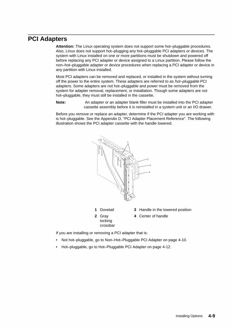
4-9Installing Options
PCI AdaptersAttention: The Linux operating system does not support some hot–pluggable procedures.Also, Linux does not support hot–plugging any hot–pluggable PCI adapters or devices. Thesystem with Linux installed on one or more partitions must be shutdown and powered offbefore replacing any PCI adapter or device assigned to a Linux partition. Please follow thenon–hot–pluggable adapter or device procedures when replacing a PCI adapter or device inany partition with Linux installed.
Most PCI adapters can be removed and replaced, or installed in the system without turningoff the power to the entire system. These adapters are referred to as hot–pluggable PCIadapters. Some adapters are not hot–pluggable and power must be removed from thesystem for adapter removal, replacement, or installation. Though some adapters are nothot–pluggable, they must still be installed in the cassette.
Note: An adapter or an adapter blank filler must be installed into the PCI adaptercassette assembly before it is reinstalled in a system unit or an I/O drawer.
Before you remove or replace an adapter, determine if the PCI adapter you are working withis hot–pluggable. See the Appendix D, “PCI Adapter Placement Reference”. The followingillustration shows the PCI adapter cassette with the handle lowered.
1
2
3
4
1 Dovetail 3 Handle in the lowered position
2 Graylockingcrossbar
4 Center of handle
If you are installing or removing a PCI adapter that is:
• Not hot–pluggable, go to Non–Hot–Pluggable PCI Adapter on page 4-10.
• Hot–pluggable, go to Hot–Pluggable PCI Adapter on page 4-12.
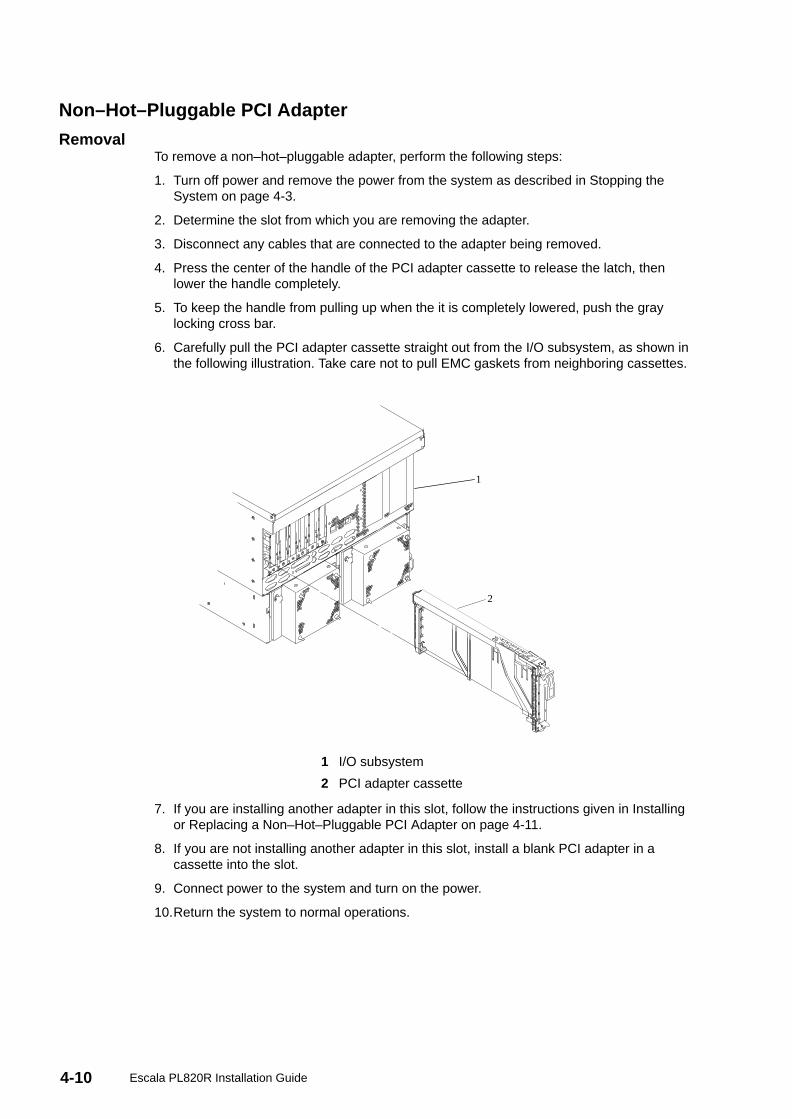
4-10 Escala PL820R Installation Guide
Non–Hot–Pluggable PCI Adapter
RemovalTo remove a non–hot–pluggable adapter, perform the following steps:
1. Turn off power and remove the power from the system as described in Stopping theSystem on page 4-3.
2. Determine the slot from which you are removing the adapter.
3. Disconnect any cables that are connected to the adapter being removed.
4. Press the center of the handle of the PCI adapter cassette to release the latch, thenlower the handle completely.
5. To keep the handle from pulling up when the it is completely lowered, push the graylocking cross bar.
6. Carefully pull the PCI adapter cassette straight out from the I/O subsystem, as shown inthe following illustration. Take care not to pull EMC gaskets from neighboring cassettes.
1
2
1 I/O subsystem
2 PCI adapter cassette
7. If you are installing another adapter in this slot, follow the instructions given in Installingor Replacing a Non–Hot–Pluggable PCI Adapter on page 4-11.
8. If you are not installing another adapter in this slot, install a blank PCI adapter in acassette into the slot.
9. Connect power to the system and turn on the power.
10.Return the system to normal operations.
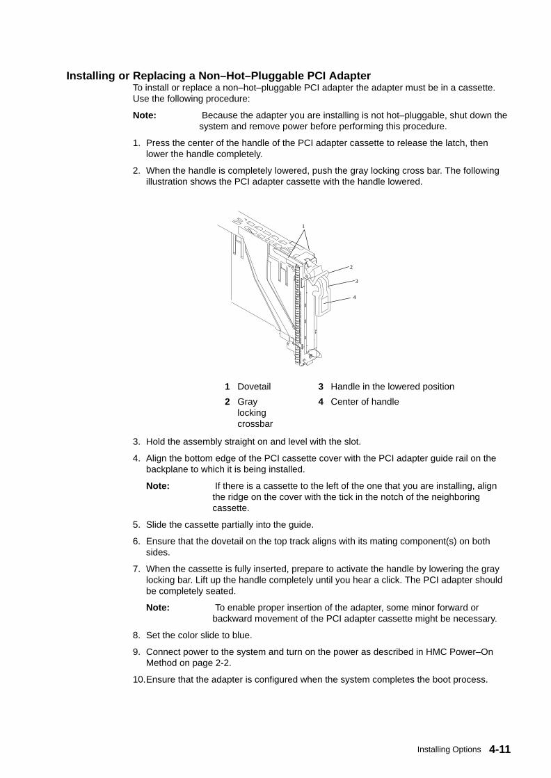
4-11Installing Options
Installing or Replacing a Non–Hot–Pluggable PCI AdapterTo install or replace a non–hot–pluggable PCI adapter the adapter must be in a cassette.Use the following procedure:
Note: Because the adapter you are installing is not hot–pluggable, shut down thesystem and remove power before performing this procedure.
1. Press the center of the handle of the PCI adapter cassette to release the latch, thenlower the handle completely.
2. When the handle is completely lowered, push the gray locking cross bar. The followingillustration shows the PCI adapter cassette with the handle lowered.
1
2
3
4
1 Dovetail 3 Handle in the lowered position
2 Graylockingcrossbar
4 Center of handle
3. Hold the assembly straight on and level with the slot.
4. Align the bottom edge of the PCI cassette cover with the PCI adapter guide rail on thebackplane to which it is being installed.
Note: If there is a cassette to the left of the one that you are installing, alignthe ridge on the cover with the tick in the notch of the neighboringcassette.
5. Slide the cassette partially into the guide.
6. Ensure that the dovetail on the top track aligns with its mating component(s) on bothsides.
7. When the cassette is fully inserted, prepare to activate the handle by lowering the graylocking bar. Lift up the handle completely until you hear a click. The PCI adapter shouldbe completely seated.
Note: To enable proper insertion of the adapter, some minor forward orbackward movement of the PCI adapter cassette might be necessary.
8. Set the color slide to blue.
9. Connect power to the system and turn on the power as described in HMC Power–OnMethod on page 2-2.
10.Ensure that the adapter is configured when the system completes the boot process.

4-12 Escala PL820R Installation Guide
Hot–Pluggable PCI Adapter
Installing a Hot–Pluggable PCI AdapterAttention: The Linux operating system does not support some hot–pluggable procedures.Also, Linux does not support hot–plugging any hot–pluggable PCI adapters or devices. Thesystem with Linux installed on one or more partitions must be shutdown and powered offbefore replacing any PCI adapter or device assigned to a Linux partition. Please follow thenon–hot–pluggable adapter or device procedures when replacing a PCI adapter or device inany partition with Linux installed.
Note: Before installing a new adapter, ensure the device driver for the adapter isinstalled. See the instructions that came with the new adapter.
To install an adapter, perform the following steps:
1. Install the new adapter into a PCI adapter cassette. See PCI Adapter or Blank FillerRemoval from a Cassette Assembly on page 4-15.
2. Log in as root user, if the system is a partitioned system, log in as root user on thepartition that has the adapter assigned to it.
3. At the command line, type smitty .
4. Select Devices .
5. Select PCI Hot Plug Manager .
6. From the PCI Hot–Plug Manager menu, select Add a PCI Hot–Plug Adapter and pressEnter. The Add a Hot–Plug Adapter window displays.
7. See the Appendix C, “PCI Adapter Placement Reference”, for adapter placementinformation. Select an empty PCI slot for the adapter.
8. Select the appropriate empty PCI slot from the ones listed on the screen, and pressEnter.
9. Follow the instructions on the screen to install the adapter until the visual indicator (LED)for the specified PCI slot is set to the Action state.
10.Install the new adapter in the adapter slot by performing the following:
a. Lower the black handle completely.
b. Push the gray locking cross bar until you hear a clicking sound.
c. Hold the assembly straight on and level with the slot.
d. Align the bottom edge of the PCI cassette cover with the PCI adapter guide rail on theI/O backplane.
Note: If there is a cassette to the left of the one that you are installing, alignthe ridge on the cover with the tick in the notch of the neighboringcassette.
e. Slide the cassette partially into the guide.
f. Ensure that the dovetail on the top track aligns with its mating component(s) on bothsides.
g. When the cassette is fully inserted, prepare to activate the handle by lowering thegray locking bar. Lift up the handle completely until you hear a click. The PCI adaptershould be completely seated.
h. Set the color slide to orange.
11.Connect the appropriate cables and devices to the adapter.
12.Continue to follow the screen instructions until you receive a message that theinstallation is successful. Successful installation is indicated by the OK messagedisplayed next to the Command field at the top of the screen.
4-13Installing Options
13.Press the F3 key to return to the PCI Hot–Plug Manager menu.
14.Select Install/Configure Devices Added After IPL and press Enter. Follow theinstructions on the screen. Successful installation is indicated by the OK messagedisplayed next to the Command field at the top of the screen.
15.If you do not have other adapters to install, continue with the next step. OR If you haveother adapters to install, press the F3 key to return to the PCI Hot–Plug Manager menuand then return to step 6 on page 4-12.
16.Press F10 to exit the Hot–Plug Manager.
Removing a Hot–Pluggable PCI AdapterAttention: The Linux operating system does not support some hot–pluggable procedures.Also, Linux does not support hot–plugging any hot–pluggable PCI adapters or devices. Thesystem with Linux installed on one or more partitions must be shutdown and powered offbefore replacing any PCI adapter or device assigned to a Linux partition. Please follow thenon–hot–pluggable adapter or device procedures when replacing a PCI adapter or device inany partition with Linux installed.
Note: If you are removing an adapter and replacing it with an adapter that isidentical to the adapter that was removed, use the procedure Replacing aHot–Pluggable PCI Adapter on page 4-57.
To remove an adapter, perform the following steps:
1. Open the door of the rack.
2. Determine the slot from which you are removing the adapter.
3. Ensure that any processes or applications that might use the adapter are stopped.
Note: Removing a hot–pluggable PCI adapter requires the systemadministrator to take the PCI adapter offline before performing any PCIadapter hot–plug procedures. Before taking an adapter offline, thedevices attached to the adapter must also be taken offline. This actionprevents a service representative or user from causing an unexpectedoutage for system users.
For more information on taking the PCI adapter online, see the AIXoperating system documentation.
4. Log in as root user, if the system is a partitioned system, log in as root user on thepartition that has the adapter assigned to it.
5. At the command line, type smitty .
6. Select Devices .
7. Select PCI Hot Plug Manager .
8. Select Unconfigure a Device and press Enter.
9. Press F4 to display the Device Names menu.
10.Select the adapter you are removing from the menu.
11.Use the Tab key to answer NO to Keep Definition . Press Enter.
12.The ARE YOU SURE screen displays. Press Enter to verify the information. Successfulunconfigure is indicated by the OK message displayed next to the Command field at thetop of the screen.
13.Press F3 to return to the PCI Hot–Plug Manager menu.
14.Select Replace/Remove a PCI Hot–Plug Adapter and press Enter. TheReplace/Remove a PCI Hot–Plug Adapter menu displays.
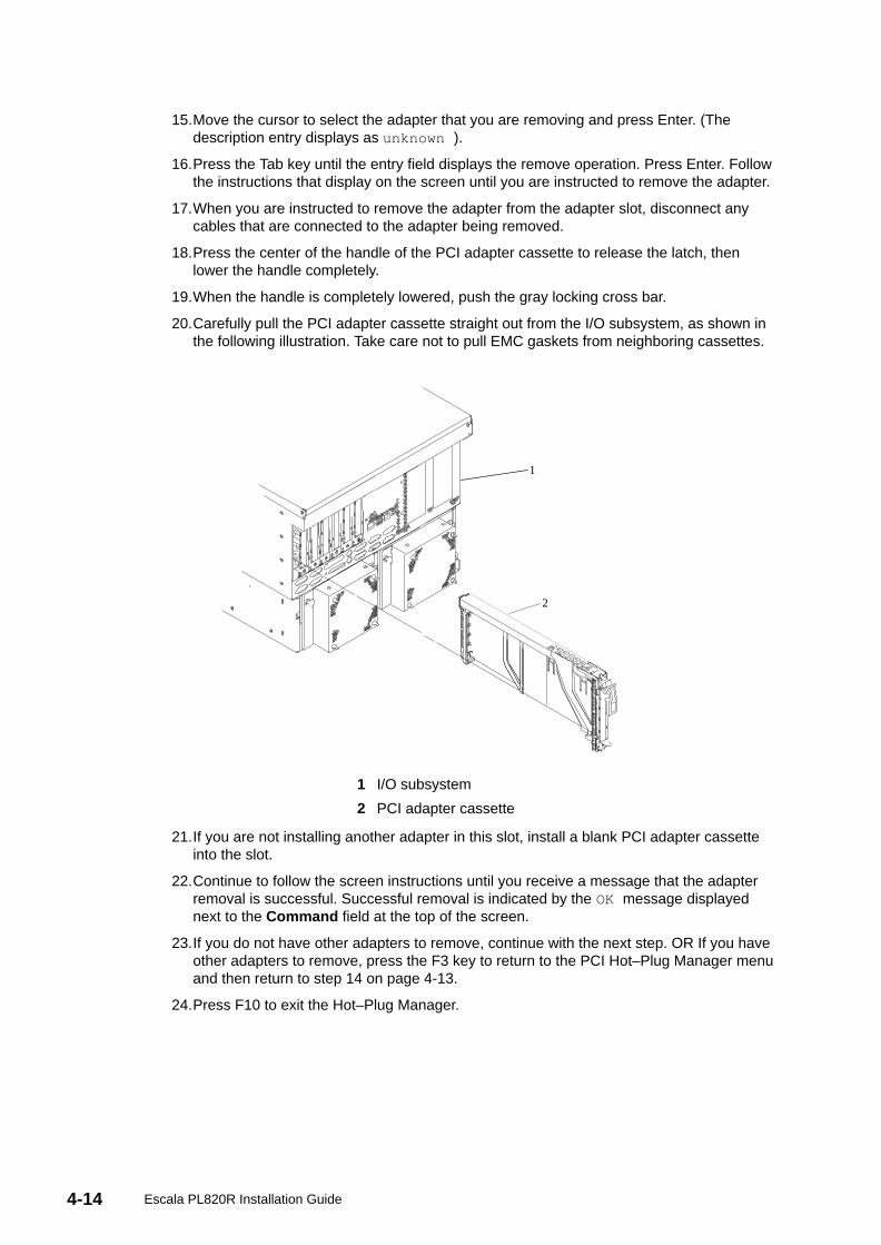
4-14 Escala PL820R Installation Guide
15.Move the cursor to select the adapter that you are removing and press Enter. (Thedescription entry displays as unknown ).
16.Press the Tab key until the entry field displays the remove operation. Press Enter. Followthe instructions that display on the screen until you are instructed to remove the adapter.
17.When you are instructed to remove the adapter from the adapter slot, disconnect anycables that are connected to the adapter being removed.
18.Press the center of the handle of the PCI adapter cassette to release the latch, thenlower the handle completely.
19.When the handle is completely lowered, push the gray locking cross bar.
20.Carefully pull the PCI adapter cassette straight out from the I/O subsystem, as shown inthe following illustration. Take care not to pull EMC gaskets from neighboring cassettes.
1
2
1 I/O subsystem
2 PCI adapter cassette
21.If you are not installing another adapter in this slot, install a blank PCI adapter cassetteinto the slot.
22.Continue to follow the screen instructions until you receive a message that the adapterremoval is successful. Successful removal is indicated by the OK message displayednext to the Command field at the top of the screen.
23.If you do not have other adapters to remove, continue with the next step. OR If you haveother adapters to remove, press the F3 key to return to the PCI Hot–Plug Manager menuand then return to step 14 on page 4-13.
24.Press F10 to exit the Hot–Plug Manager.
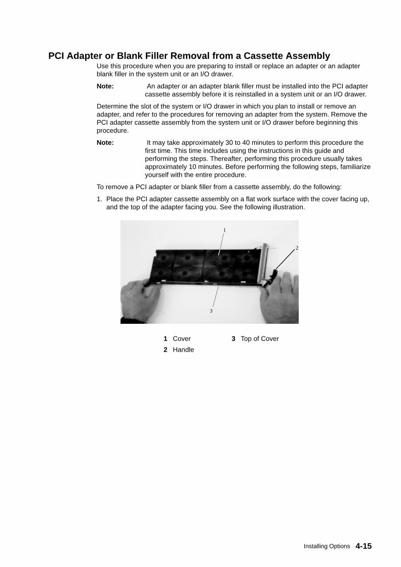
4-15Installing Options
PCI Adapter or Blank Filler Removal from a Cassette AssemblyUse this procedure when you are preparing to install or replace an adapter or an adapterblank filler in the system unit or an I/O drawer.
Note: An adapter or an adapter blank filler must be installed into the PCI adaptercassette assembly before it is reinstalled in a system unit or an I/O drawer.
Determine the slot of the system or I/O drawer in which you plan to install or remove anadapter, and refer to the procedures for removing an adapter from the system. Remove thePCI adapter cassette assembly from the system unit or I/O drawer before beginning thisprocedure.
Note: It may take approximately 30 to 40 minutes to perform this procedure thefirst time. This time includes using the instructions in this guide andperforming the steps. Thereafter, performing this procedure usually takesapproximately 10 minutes. Before performing the following steps, familiarizeyourself with the entire procedure.
To remove a PCI adapter or blank filler from a cassette assembly, do the following:
1. Place the PCI adapter cassette assembly on a flat work surface with the cover facing up,and the top of the adapter facing you. See the following illustration.
1
2
3
1 Cover 3 Top of Cover
2 Handle
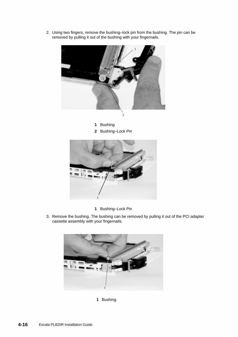
4-16 Escala PL820R Installation Guide
2. Using two fingers, remove the bushing–lock pin from the bushing. The pin can beremoved by pulling it out of the bushing with your fingernails.
1
2
1 Bushing
2 Bushing–Lock Pin
1
1 Bushing–Lock Pin
3. Remove the bushing. The bushing can be removed by pulling it out of the PCI adaptercassette assembly with your fingernails.
1
1 Bushing
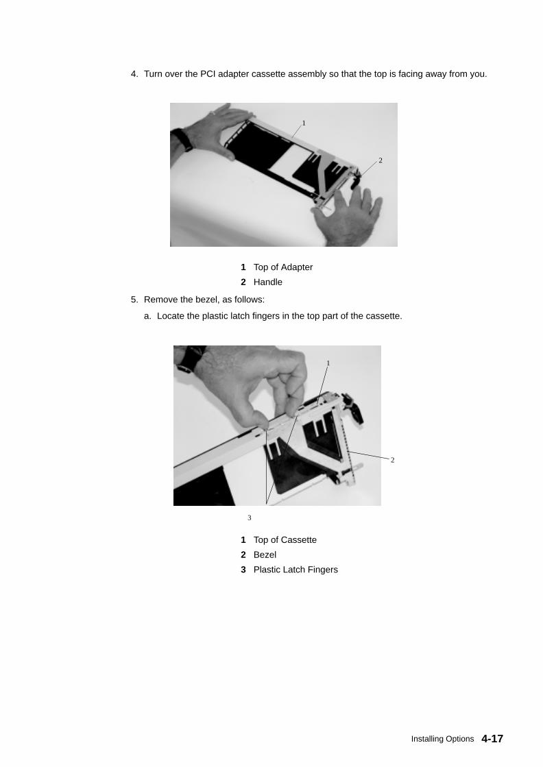
4-17Installing Options
4. Turn over the PCI adapter cassette assembly so that the top is facing away from you.
1
2
1 Top of Adapter
2 Handle
5. Remove the bezel, as follows:
a. Locate the plastic latch fingers in the top part of the cassette.
1
2
3
1 Top of Cassette
2 Bezel
3 Plastic Latch Fingers
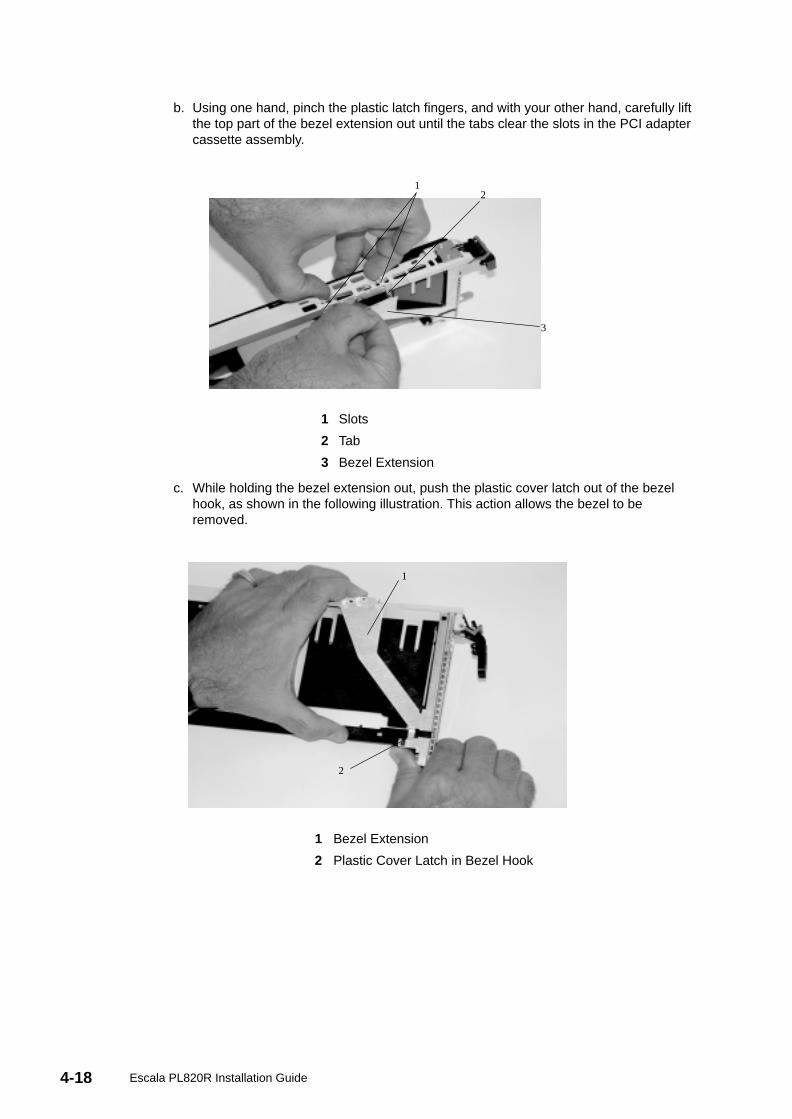
4-18 Escala PL820R Installation Guide
b. Using one hand, pinch the plastic latch fingers, and with your other hand, carefully liftthe top part of the bezel extension out until the tabs clear the slots in the PCI adaptercassette assembly.
12
3
1 Slots
2 Tab
3 Bezel Extension
c. While holding the bezel extension out, push the plastic cover latch out of the bezelhook, as shown in the following illustration. This action allows the bezel to beremoved.
1
2
1 Bezel Extension
2 Plastic Cover Latch in Bezel Hook
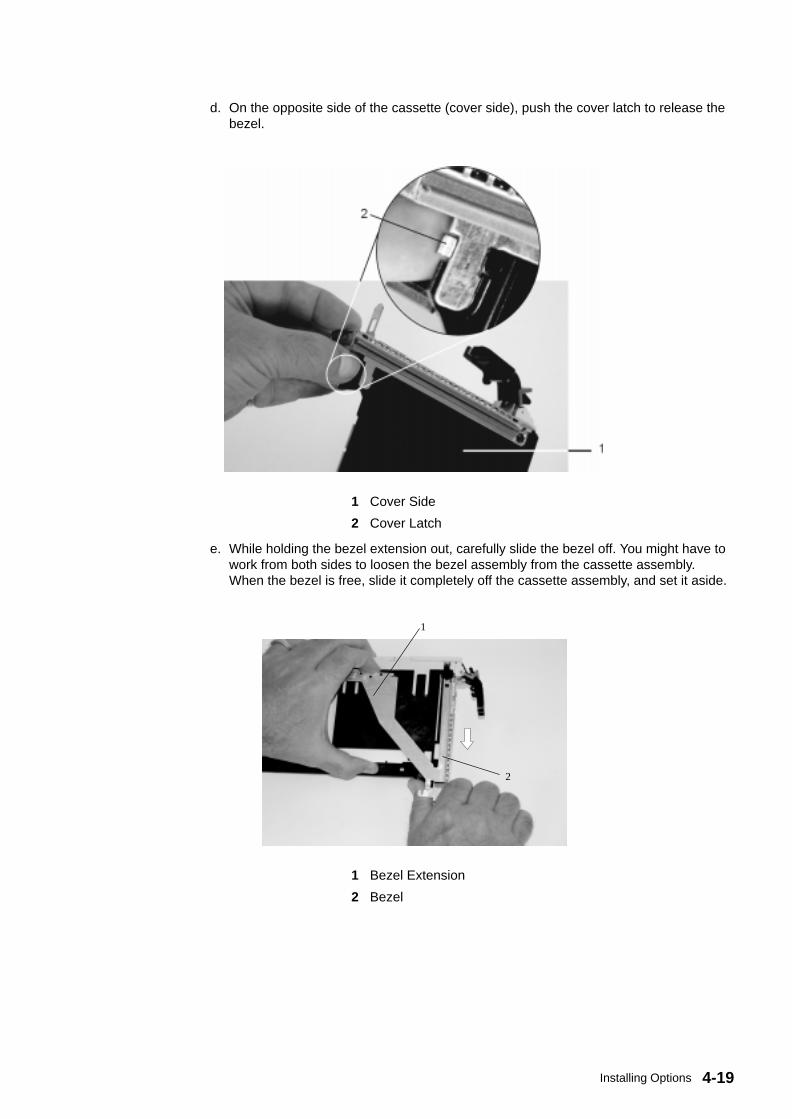
4-19Installing Options
d. On the opposite side of the cassette (cover side), push the cover latch to release thebezel.
1 Cover Side
2 Cover Latch
e. While holding the bezel extension out, carefully slide the bezel off. You might have towork from both sides to loosen the bezel assembly from the cassette assembly.When the bezel is free, slide it completely off the cassette assembly, and set it aside.
1
2
1 Bezel Extension
2 Bezel
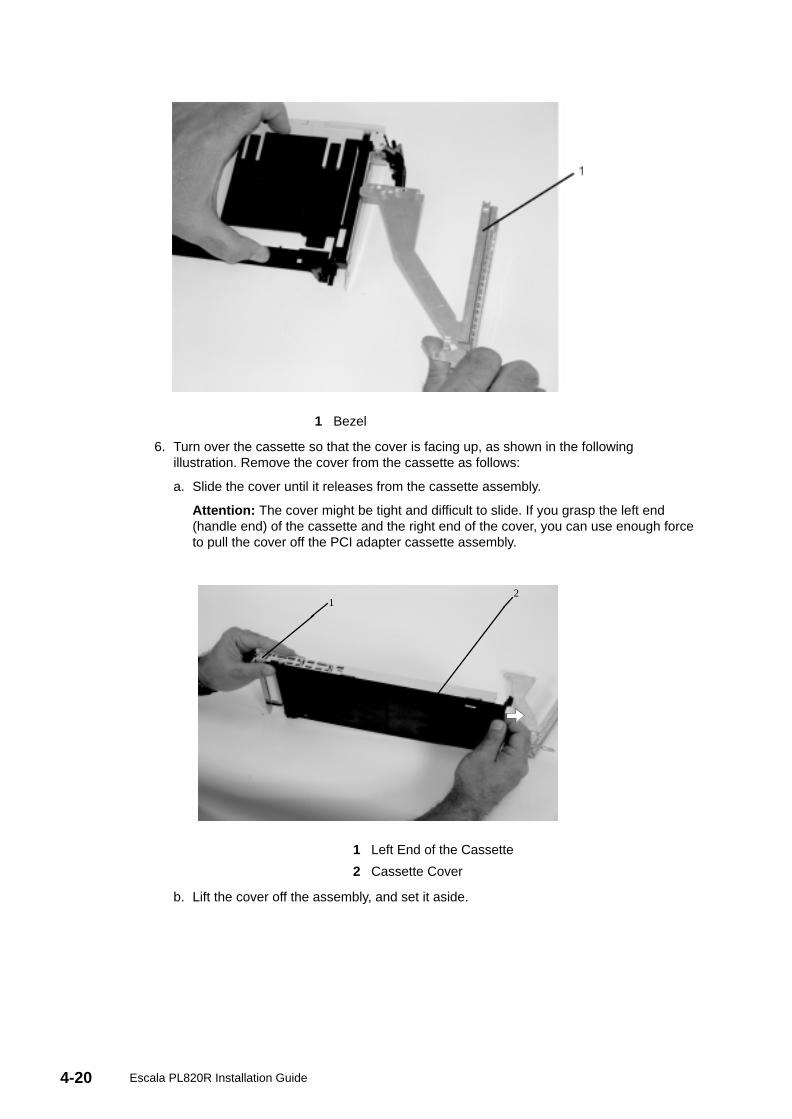
4-20 Escala PL820R Installation Guide
1 Bezel
6. Turn over the cassette so that the cover is facing up, as shown in the followingillustration. Remove the cover from the cassette as follows:
a. Slide the cover until it releases from the cassette assembly.
Attention: The cover might be tight and difficult to slide. If you grasp the left end(handle end) of the cassette and the right end of the cover, you can use enough forceto pull the cover off the PCI adapter cassette assembly.
12
1 Left End of the Cassette
2 Cassette Cover
b. Lift the cover off the assembly, and set it aside.
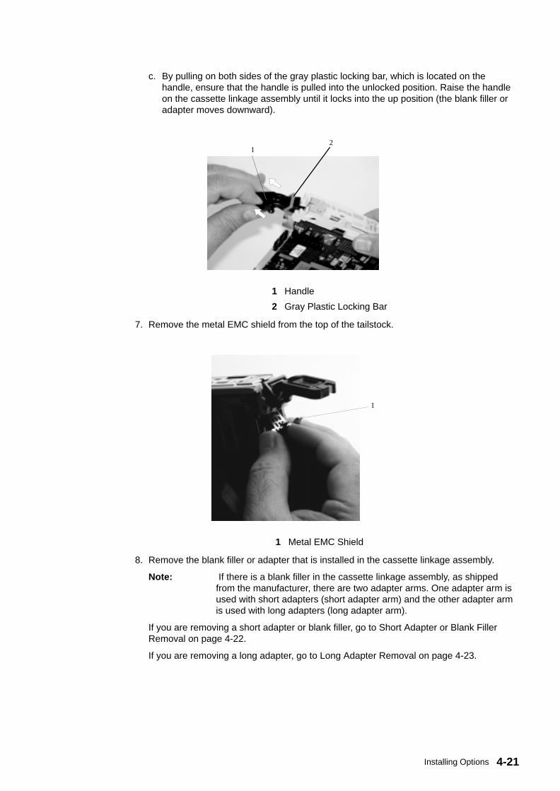
4-21Installing Options
c. By pulling on both sides of the gray plastic locking bar, which is located on thehandle, ensure that the handle is pulled into the unlocked position. Raise the handleon the cassette linkage assembly until it locks into the up position (the blank filler oradapter moves downward).
12
1 Handle
2 Gray Plastic Locking Bar
7. Remove the metal EMC shield from the top of the tailstock.
1
1 Metal EMC Shield
8. Remove the blank filler or adapter that is installed in the cassette linkage assembly.
Note: If there is a blank filler in the cassette linkage assembly, as shippedfrom the manufacturer, there are two adapter arms. One adapter arm isused with short adapters (short adapter arm) and the other adapter armis used with long adapters (long adapter arm).
If you are removing a short adapter or blank filler, go to Short Adapter or Blank FillerRemoval on page 4-22.
If you are removing a long adapter, go to Long Adapter Removal on page 4-23.

4-22 Escala PL820R Installation Guide
Short Adapter or Blank Filler RemovalTo remove a short adapter or blank filler, do the following:
1. Slide the long and short adapter arms away from the adapter or blank filler by doing thefollowing:
a. Each adapter arm has a release tab that allows the arm to be moved away from theadapter or blank filler in the cassette assembly. Use your fingernail to lift the tab, toallow each arm to be moved away from the adapter or blank filler. Lift the release tabon the short adapter arm, and push on the slotted tab to release the end of the blankfiller.
Note: If you plan to install a short adapter, leave the long adapter arm onthe cassette linkage assembly. If you plan to install a long adapter,remove both the long and short adapter arms from the cassettelinkage assembly in the next step.
b. Slide the long and short adapter arms away from the blank filler or adapter.
1
2
3
45
1 LongAdapter Arm
4 Short Adapter Arm
2 Release Tab 5 Slotted Tab
3 Release Tab
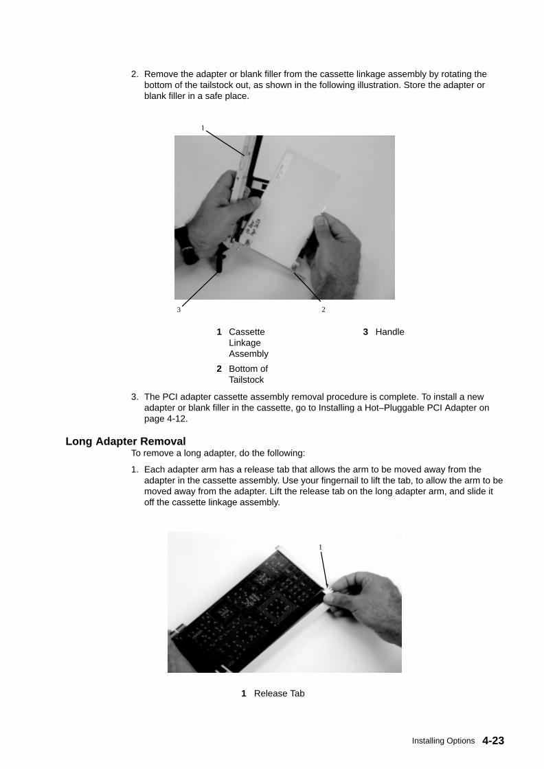
4-23Installing Options
2. Remove the adapter or blank filler from the cassette linkage assembly by rotating thebottom of the tailstock out, as shown in the following illustration. Store the adapter orblank filler in a safe place.
1
23
1 CassetteLinkageAssembly
3 Handle
2 Bottom ofTailstock
3. The PCI adapter cassette assembly removal procedure is complete. To install a newadapter or blank filler in the cassette, go to Installing a Hot–Pluggable PCI Adapter onpage 4-12.
Long Adapter RemovalTo remove a long adapter, do the following:
1. Each adapter arm has a release tab that allows the arm to be moved away from theadapter in the cassette assembly. Use your fingernail to lift the tab, to allow the arm to bemoved away from the adapter. Lift the release tab on the long adapter arm, and slide itoff the cassette linkage assembly.
1
1 Release Tab
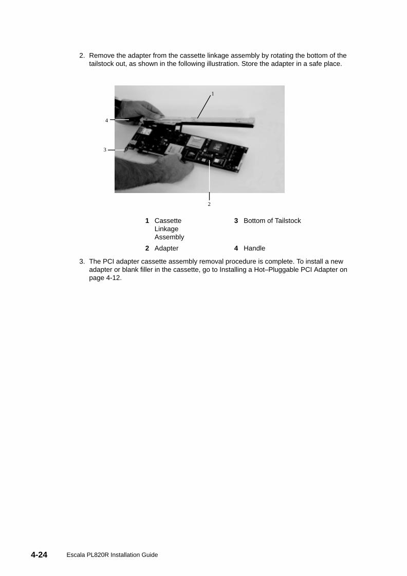
4-24 Escala PL820R Installation Guide
2. Remove the adapter from the cassette linkage assembly by rotating the bottom of thetailstock out, as shown in the following illustration. Store the adapter in a safe place.
1
2
3
4
1 CassetteLinkageAssembly
3 Bottom of Tailstock
2 Adapter 4 Handle
3. The PCI adapter cassette assembly removal procedure is complete. To install a newadapter or blank filler in the cassette, go to Installing a Hot–Pluggable PCI Adapter onpage 4-12.
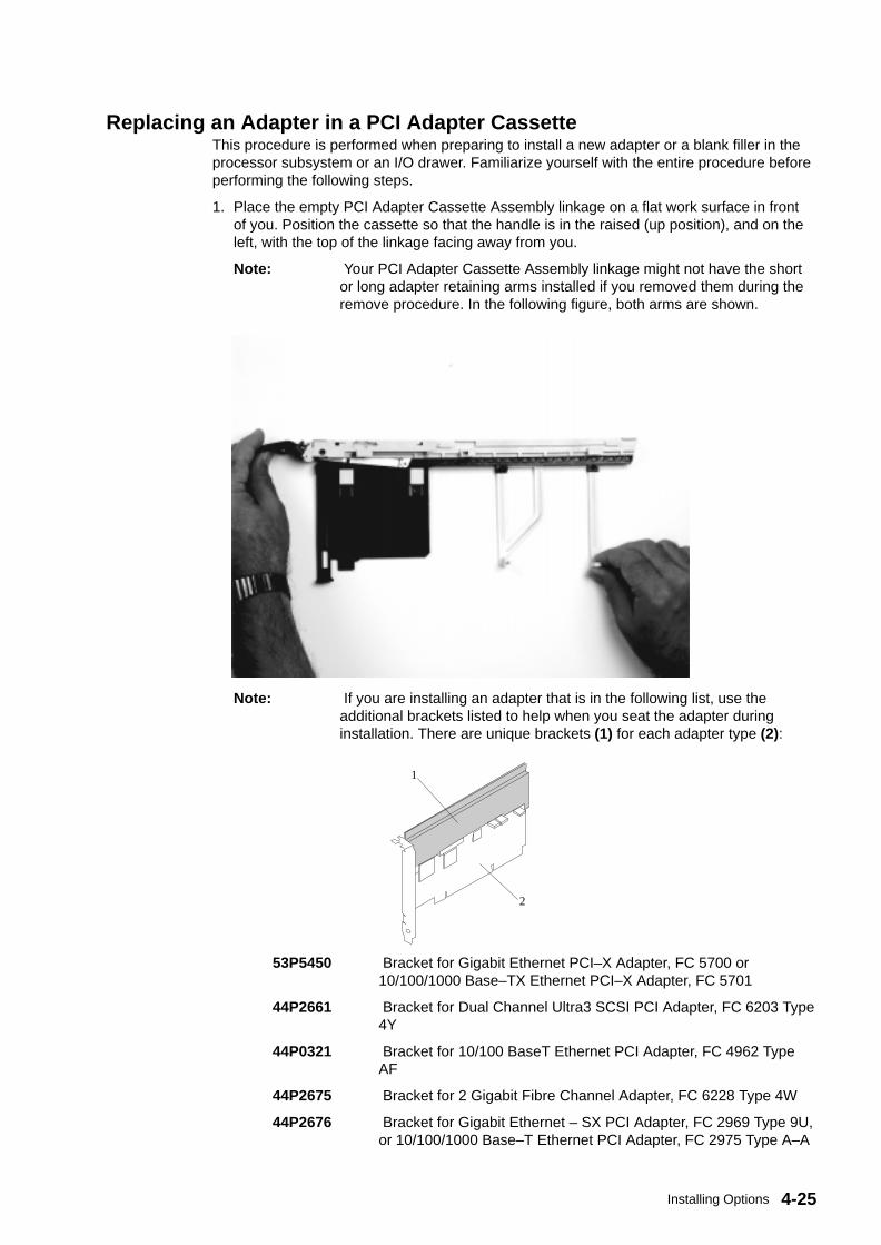
4-25Installing Options
Replacing an Adapter in a PCI Adapter CassetteThis procedure is performed when preparing to install a new adapter or a blank filler in theprocessor subsystem or an I/O drawer. Familiarize yourself with the entire procedure beforeperforming the following steps.
1. Place the empty PCI Adapter Cassette Assembly linkage on a flat work surface in frontof you. Position the cassette so that the handle is in the raised (up position), and on theleft, with the top of the linkage facing away from you.
Note: Your PCI Adapter Cassette Assembly linkage might not have the shortor long adapter retaining arms installed if you removed them during theremove procedure. In the following figure, both arms are shown.
Note: If you are installing an adapter that is in the following list, use theadditional brackets listed to help when you seat the adapter duringinstallation. There are unique brackets (1) for each adapter type (2):
1
2
53P5450 Bracket for Gigabit Ethernet PCI–X Adapter, FC 5700 or10/100/1000 Base–TX Ethernet PCI–X Adapter, FC 5701
44P2661 Bracket for Dual Channel Ultra3 SCSI PCI Adapter, FC 6203 Type4Y
44P0321 Bracket for 10/100 BaseT Ethernet PCI Adapter, FC 4962 TypeAF
44P2675 Bracket for 2 Gigabit Fibre Channel Adapter, FC 6228 Type 4W
44P2676 Bracket for Gigabit Ethernet – SX PCI Adapter, FC 2969 Type 9U,or 10/100/1000 Base–T Ethernet PCI Adapter, FC 2975 Type A–A
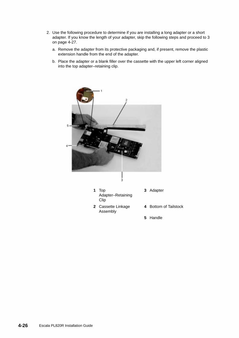
4-26 Escala PL820R Installation Guide
2. Use the following procedure to determine if you are installing a long adapter or a shortadapter. If you know the length of your adapter, skip the following steps and proceed to 3on page 4-27.
a. Remove the adapter from its protective packaging and, if present, remove the plasticextension handle from the end of the adapter.
b. Place the adapter or a blank filler over the cassette with the upper left corner alignedinto the top adapter–retaining clip.
1 TopAdapter–RetainingClip
3 Adapter
2 Cassette LinkageAssembly
4 Bottom of Tailstock
5 Handle
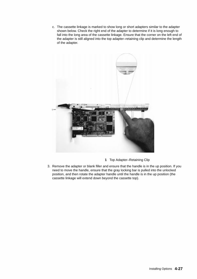
4-27Installing Options
c. The cassette linkage is marked to show long or short adapters similar to the adaptershown below. Check the right end of the adapter to determine if it is long enough tofall into the long area of the cassette linkage. Ensure that the corner on the left end ofthe adapter is still aligned into the top adapter–retaining clip and determine the lengthof the adapter.
1 Top Adapter–Retaining Clip
3. Remove the adapter or blank filler and ensure that the handle is in the up position. If youneed to move the handle, ensure that the gray locking bar is pulled into the unlockedposition, and then rotate the adapter handle until the handle is in the up position (thecassette linkage will extend down beyond the cassette top).

4-28 Escala PL820R Installation Guide
1 Handle
2 Lock
If you are installing a short adapter or blank filler, proceed to Short Adapter or Blank FillerInstallation on page 4-29. If you are installing a long adapter, proceed to Long AdapterInstallation on page 4-43.
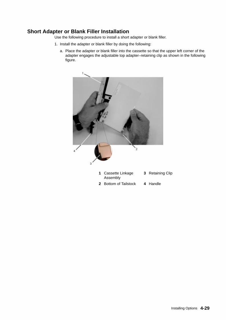
4-29Installing Options
Short Adapter or Blank Filler InstallationUse the following procedure to install a short adapter or blank filler.
1. Install the adapter or blank filler by doing the following:
a. Place the adapter or blank filler into the cassette so that the upper left corner of theadapter engages the adjustable top adapter–retaining clip as shown in the followingfigure.
1 Cassette LinkageAssembly
3 Retaining Clip
2 Bottom of Tailstock 4 Handle
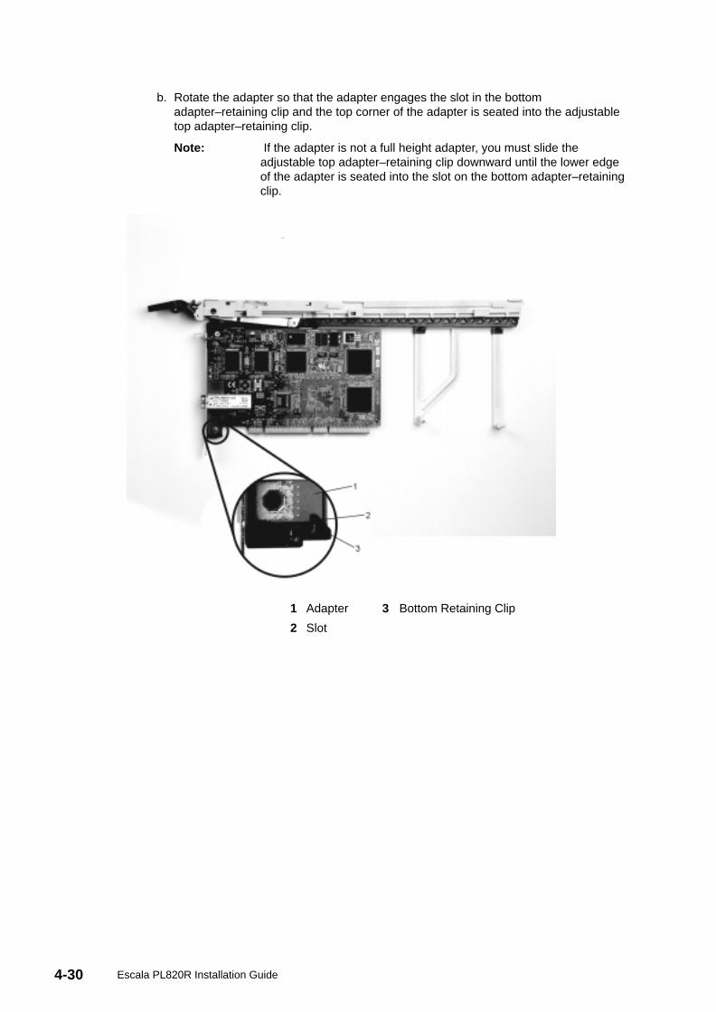
4-30 Escala PL820R Installation Guide
b. Rotate the adapter so that the adapter engages the slot in the bottomadapter–retaining clip and the top corner of the adapter is seated into the adjustabletop adapter–retaining clip.
Note: If the adapter is not a full height adapter, you must slide theadjustable top adapter–retaining clip downward until the lower edgeof the adapter is seated into the slot on the bottom adapter–retainingclip.
1 Adapter 3 Bottom Retaining Clip
2 Slot
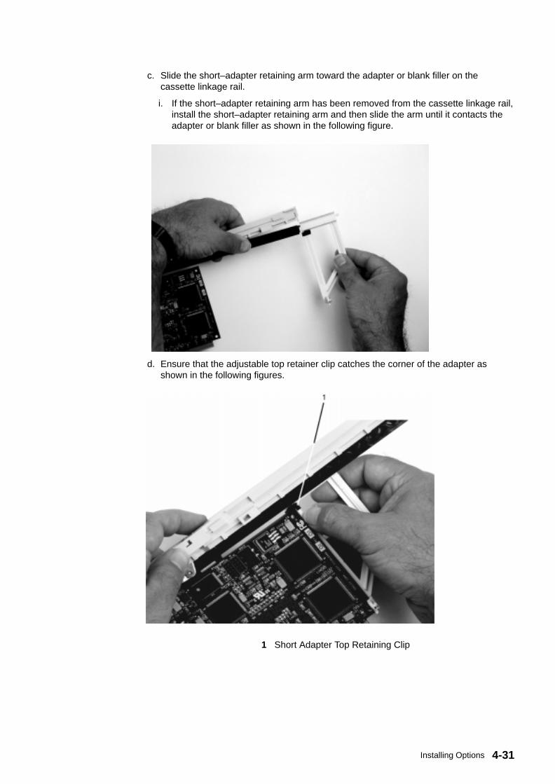
4-31Installing Options
c. Slide the short–adapter retaining arm toward the adapter or blank filler on thecassette linkage rail.
i. If the short–adapter retaining arm has been removed from the cassette linkage rail,install the short–adapter retaining arm and then slide the arm until it contacts theadapter or blank filler as shown in the following figure.
d. Ensure that the adjustable top retainer clip catches the corner of the adapter asshown in the following figures.
1 Short Adapter Top Retaining Clip
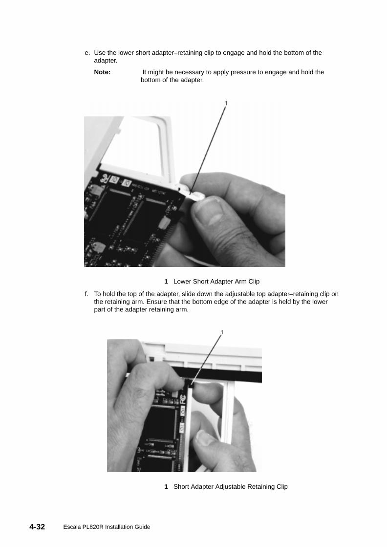
4-32 Escala PL820R Installation Guide
e. Use the lower short adapter–retaining clip to engage and hold the bottom of theadapter.
Note: It might be necessary to apply pressure to engage and hold thebottom of the adapter.
1 Lower Short Adapter Arm Clip
f. To hold the top of the adapter, slide down the adjustable top adapter–retaining clip onthe retaining arm. Ensure that the bottom edge of the adapter is held by the lowerpart of the adapter retaining arm.
1 Short Adapter Adjustable Retaining Clip
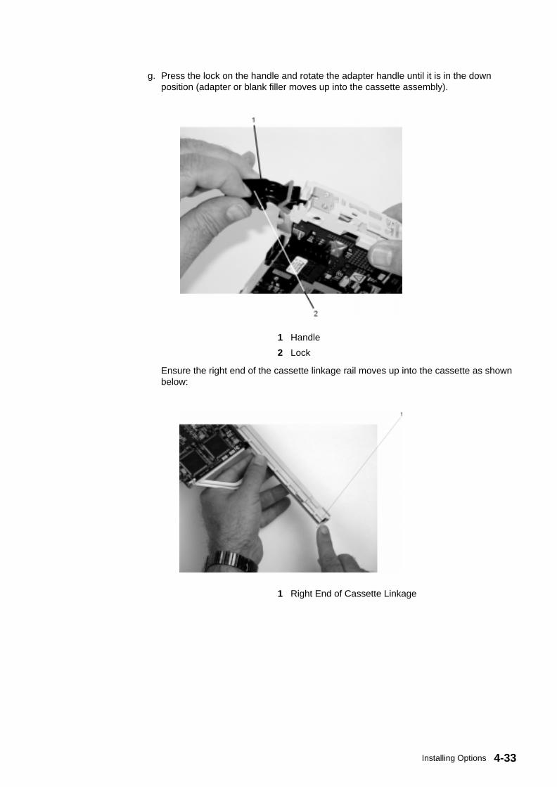
4-33Installing Options
g. Press the lock on the handle and rotate the adapter handle until it is in the downposition (adapter or blank filler moves up into the cassette assembly).
1 Handle
2 Lock
Ensure the right end of the cassette linkage rail moves up into the cassette as shownbelow:
1 Right End of Cassette Linkage
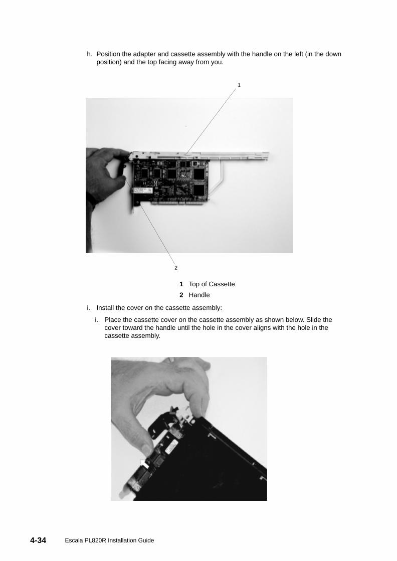
4-34 Escala PL820R Installation Guide
h. Position the adapter and cassette assembly with the handle on the left (in the downposition) and the top facing away from you.
2
1
1 Top of Cassette
2 Handle
i. Install the cover on the cassette assembly:
i. Place the cassette cover on the cassette assembly as shown below. Slide thecover toward the handle until the hole in the cover aligns with the hole in thecassette assembly.
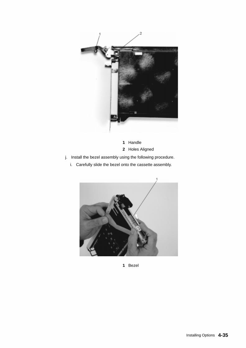
4-35Installing Options
1 Handle
2 Holes Aligned
j. Install the bezel assembly using the following procedure.
i. Carefully slide the bezel onto the cassette assembly.
1 Bezel
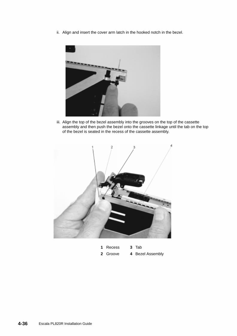
4-36 Escala PL820R Installation Guide
ii. Align and insert the cover arm latch in the hooked notch in the bezel.
iii. Align the top of the bezel assembly into the grooves on the top of the cassetteassembly and then push the bezel onto the cassette linkage until the tab on the topof the bezel is seated in the recess of the cassette assembly.
1 Recess 3 Tab
2 Groove 4 Bezel Assembly
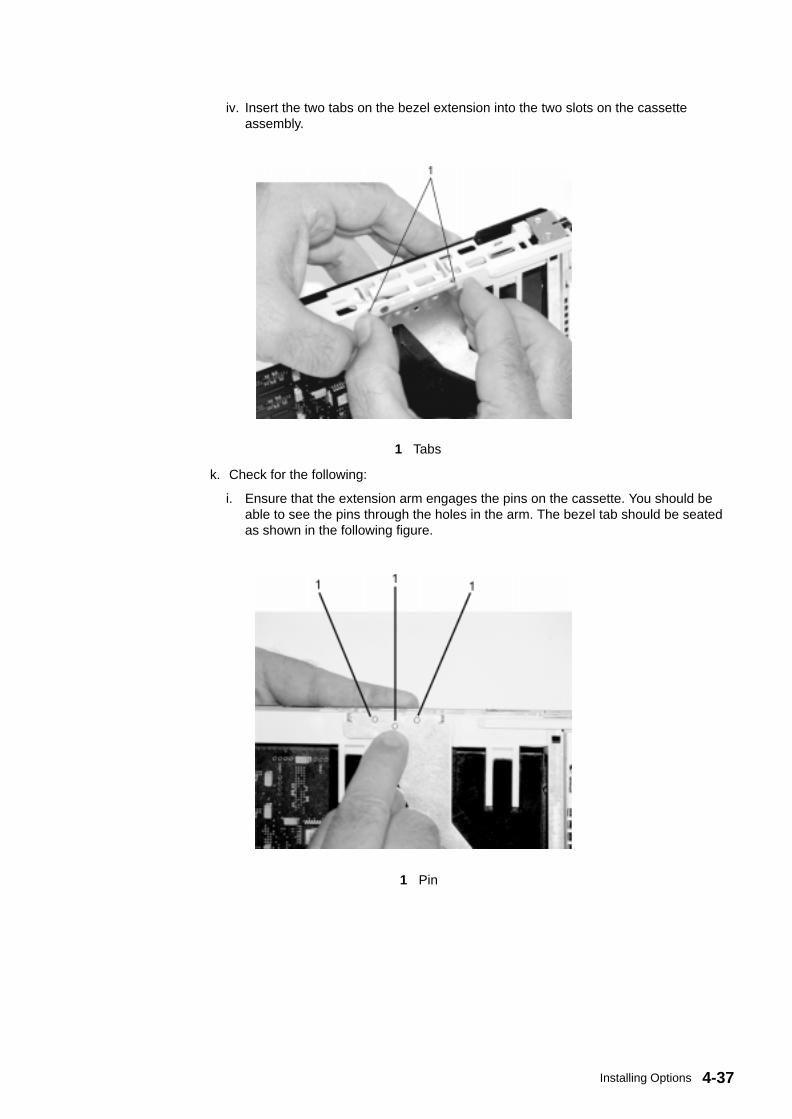
4-37Installing Options
iv. Insert the two tabs on the bezel extension into the two slots on the cassetteassembly.
1 Tabs
k. Check for the following:
i. Ensure that the extension arm engages the pins on the cassette. You should beable to see the pins through the holes in the arm. The bezel tab should be seatedas shown in the following figure.
1 Pin
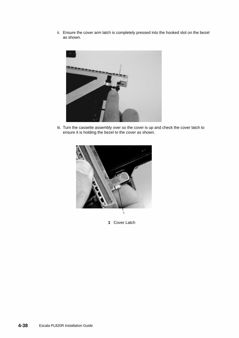
4-38 Escala PL820R Installation Guide
ii. Ensure the cover arm latch is completely pressed into the hooked slot on the bezelas shown.
iii. Turn the cassette assembly over so the cover is up and check the cover latch toensure it is holding the bezel to the cover as shown.
1
1 Cover Latch
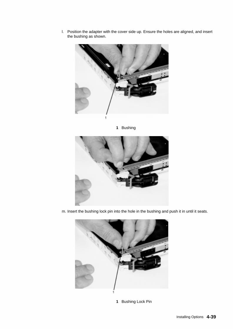
4-39Installing Options
l. Position the adapter with the cover side up. Ensure the holes are aligned, and insertthe bushing as shown.
1 Bushing
m. Insert the bushing lock pin into the hole in the bushing and push it in until it seats.
1 Bushing Lock Pin
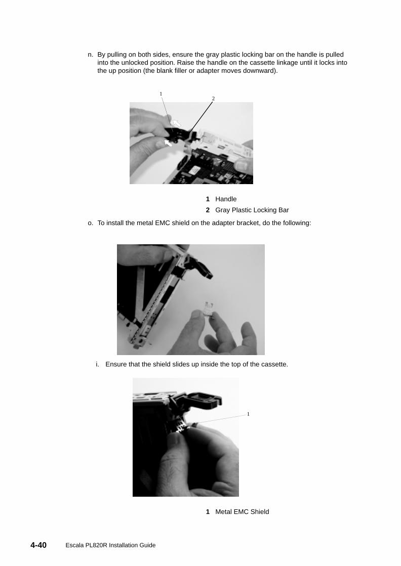
4-40 Escala PL820R Installation Guide
n. By pulling on both sides, ensure the gray plastic locking bar on the handle is pulledinto the unlocked position. Raise the handle on the cassette linkage until it locks intothe up position (the blank filler or adapter moves downward).
12
1 Handle
2 Gray Plastic Locking Bar
o. To install the metal EMC shield on the adapter bracket, do the following:
i. Ensure that the shield slides up inside the top of the cassette.
1
1 Metal EMC Shield
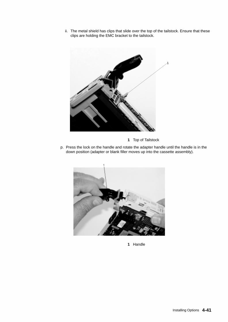
4-41Installing Options
ii. The metal shield has clips that slide over the top of the tailstock. Ensure that theseclips are holding the EMC bracket to the tailstock.
1
1 Top of Tailstock
p. Press the lock on the handle and rotate the adapter handle until the handle is in thedown position (adapter or blank filler moves up into the cassette assembly).
1 Handle
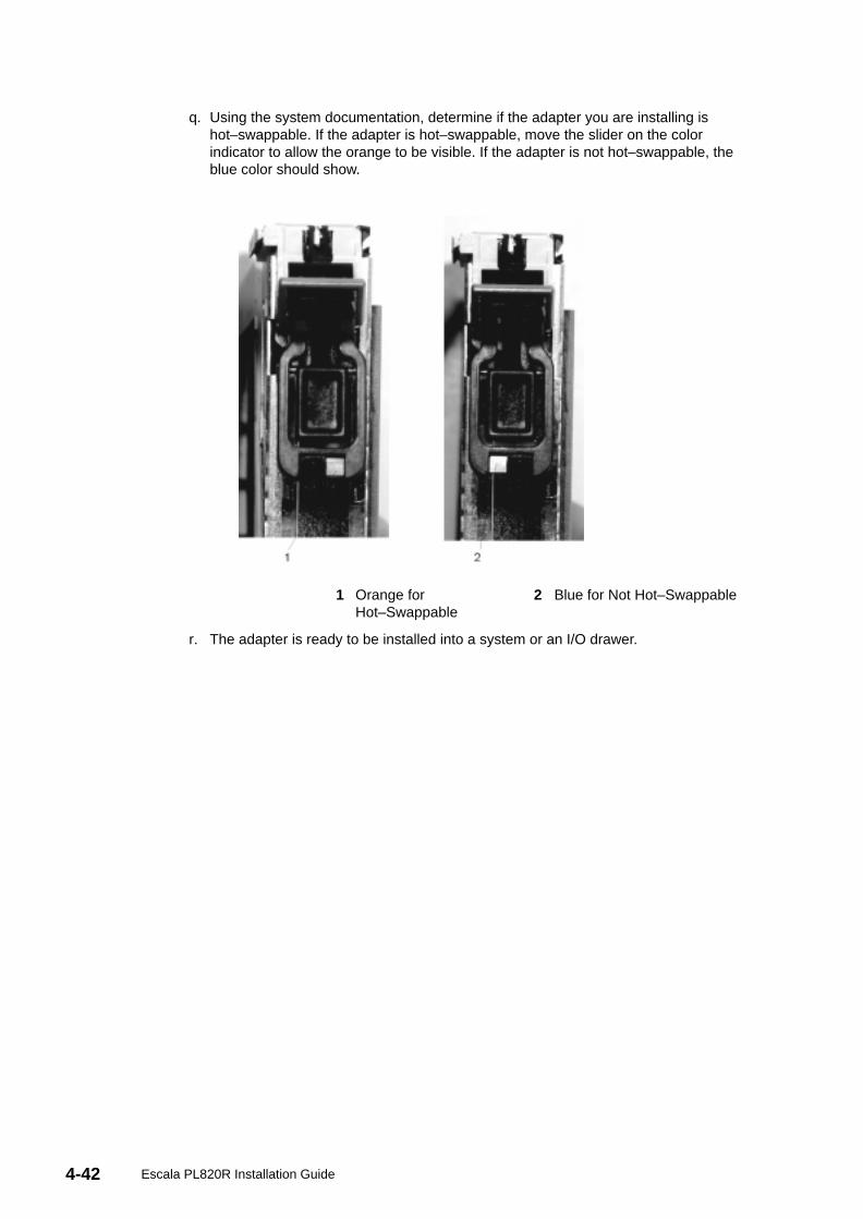
4-42 Escala PL820R Installation Guide
q. Using the system documentation, determine if the adapter you are installing ishot–swappable. If the adapter is hot–swappable, move the slider on the colorindicator to allow the orange to be visible. If the adapter is not hot–swappable, theblue color should show.
1 Orange forHot–Swappable
2 Blue for Not Hot–Swappable
r. The adapter is ready to be installed into a system or an I/O drawer.
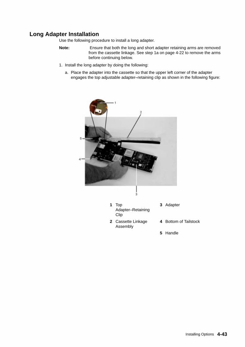
4-43Installing Options
Long Adapter InstallationUse the following procedure to install a long adapter.
Note: Ensure that both the long and short adapter retaining arms are removedfrom the cassette linkage. See step 1a on page 4-22 to remove the armsbefore continuing below.
1. Install the long adapter by doing the following:
a. Place the adapter into the cassette so that the upper left corner of the adapterengages the top adjustable adapter–retaining clip as shown in the following figure:
1 TopAdapter–RetainingClip
3 Adapter
2 Cassette LinkageAssembly
4 Bottom of Tailstock
5 Handle
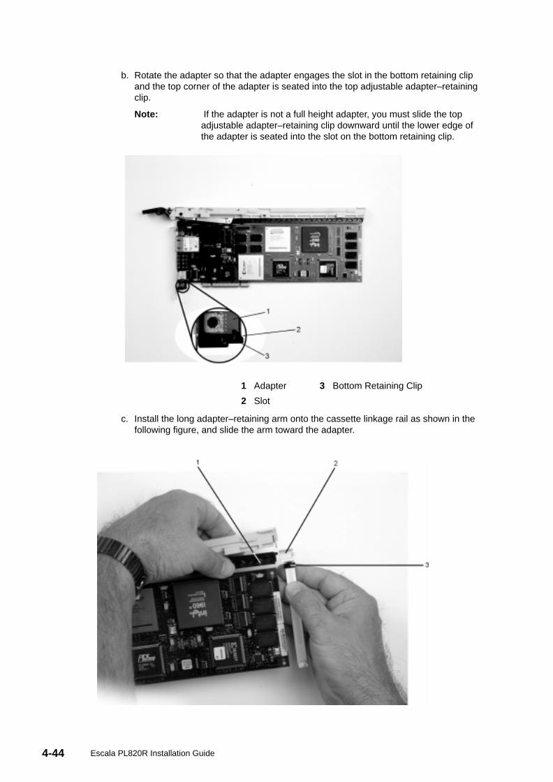
4-44 Escala PL820R Installation Guide
b. Rotate the adapter so that the adapter engages the slot in the bottom retaining clipand the top corner of the adapter is seated into the top adjustable adapter–retainingclip.
Note: If the adapter is not a full height adapter, you must slide the topadjustable adapter–retaining clip downward until the lower edge ofthe adapter is seated into the slot on the bottom retaining clip.
1 Adapter 3 Bottom Retaining Clip
2 Slot
c. Install the long adapter–retaining arm onto the cassette linkage rail as shown in thefollowing figure, and slide the arm toward the adapter.
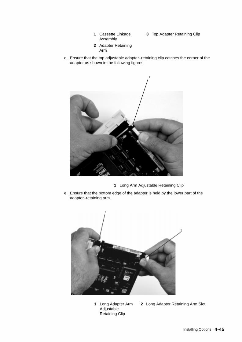
4-45Installing Options
1 Cassette LinkageAssembly
3 Top Adapter Retaining Clip
2 Adapter RetainingArm
d. Ensure that the top adjustable adapter–retaining clip catches the corner of theadapter as shown in the following figures.
1
1 Long Arm Adjustable Retaining Clip
e. Ensure that the bottom edge of the adapter is held by the lower part of theadapter–retaining arm.
1 Long Adapter ArmAdjustableRetaining Clip
2 Long Adapter Retaining Arm Slot
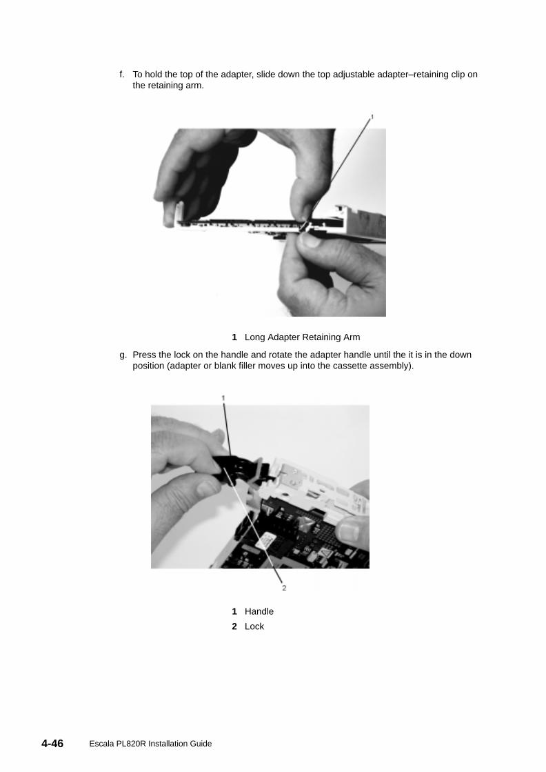
4-46 Escala PL820R Installation Guide
f. To hold the top of the adapter, slide down the top adjustable adapter–retaining clip onthe retaining arm.
1 Long Adapter Retaining Arm
g. Press the lock on the handle and rotate the adapter handle until the it is in the downposition (adapter or blank filler moves up into the cassette assembly).
1 Handle
2 Lock
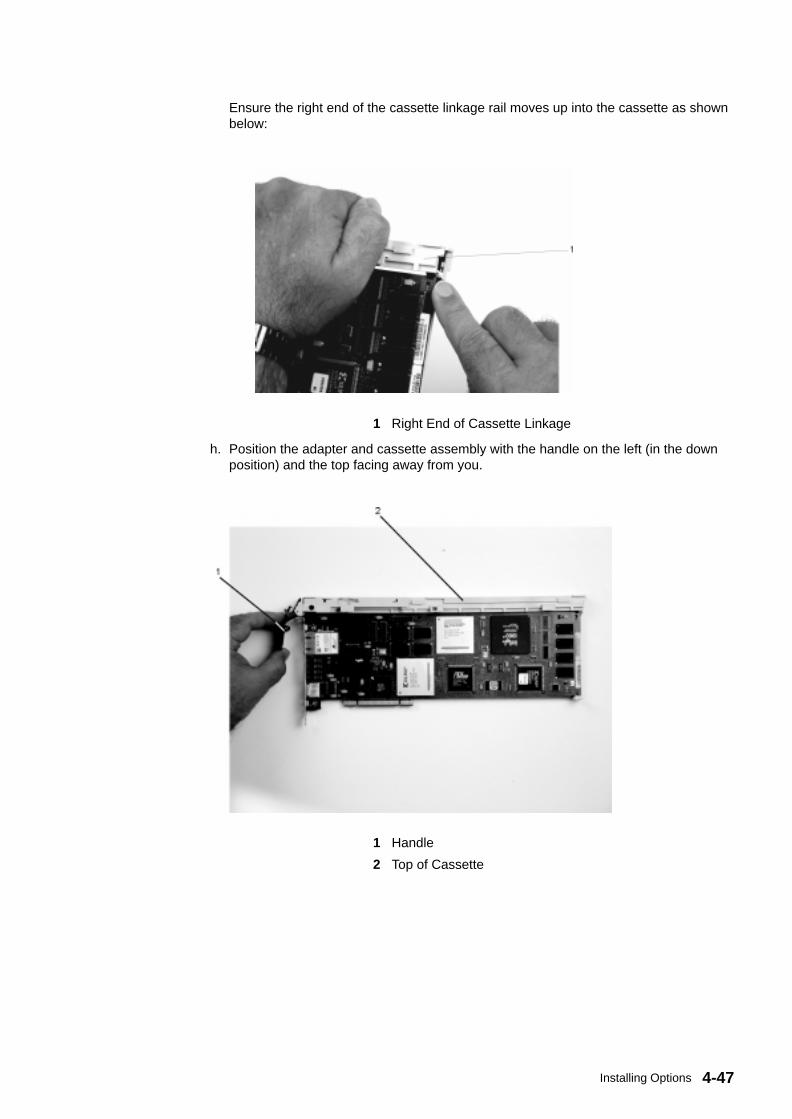
4-47Installing Options
Ensure the right end of the cassette linkage rail moves up into the cassette as shownbelow:
1 Right End of Cassette Linkage
h. Position the adapter and cassette assembly with the handle on the left (in the downposition) and the top facing away from you.
1 Handle
2 Top of Cassette
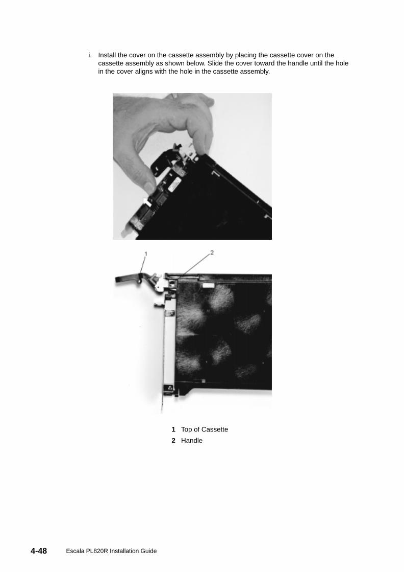
4-48 Escala PL820R Installation Guide
i. Install the cover on the cassette assembly by placing the cassette cover on thecassette assembly as shown below. Slide the cover toward the handle until the holein the cover aligns with the hole in the cassette assembly.
1 Top of Cassette
2 Handle
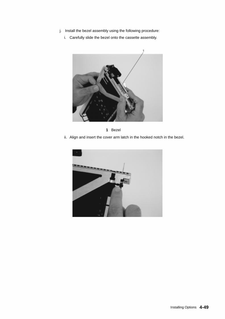
4-49Installing Options
j. Install the bezel assembly using the following procedure:
i. Carefully slide the bezel onto the cassette assembly.
1 Bezel
ii. Align and insert the cover arm latch in the hooked notch in the bezel.

4-50 Escala PL820R Installation Guide
iii. Align the top of the bezel assembly into the grooves on the top of the cassetteassembly and then push the bezel onto the cassette linkage until the tab on the topof the bezel is seated in the recess of the cassette assembly.
1 Recess 3 Tab
2 Groove 4 Bezel
iv. Insert the two tabs on the bezel extension into the two slots on the cassetteassembly.
1 Tabs

4-51Installing Options
k. Check for the following:
i. Ensure that extension arm engages the pins on the cassette. You should be ableto see the pins through the holes in the arm. The bezel tab should be seated asshown in the following figure.
1 Pins
ii. Ensure the cover arm latch is completely pressed into the hooked slot on the bezelas shown.
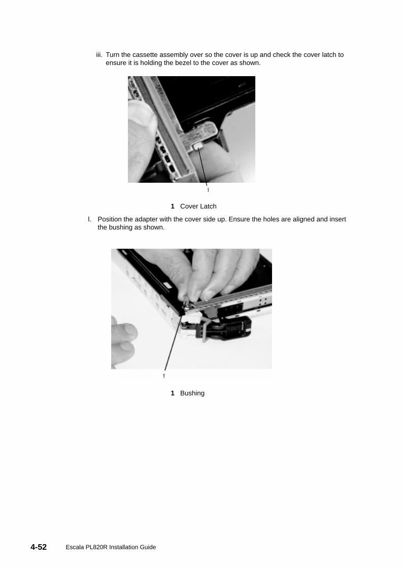
4-52 Escala PL820R Installation Guide
iii. Turn the cassette assembly over so the cover is up and check the cover latch toensure it is holding the bezel to the cover as shown.
1
1 Cover Latch
l. Position the adapter with the cover side up. Ensure the holes are aligned and insertthe bushing as shown.
1 Bushing
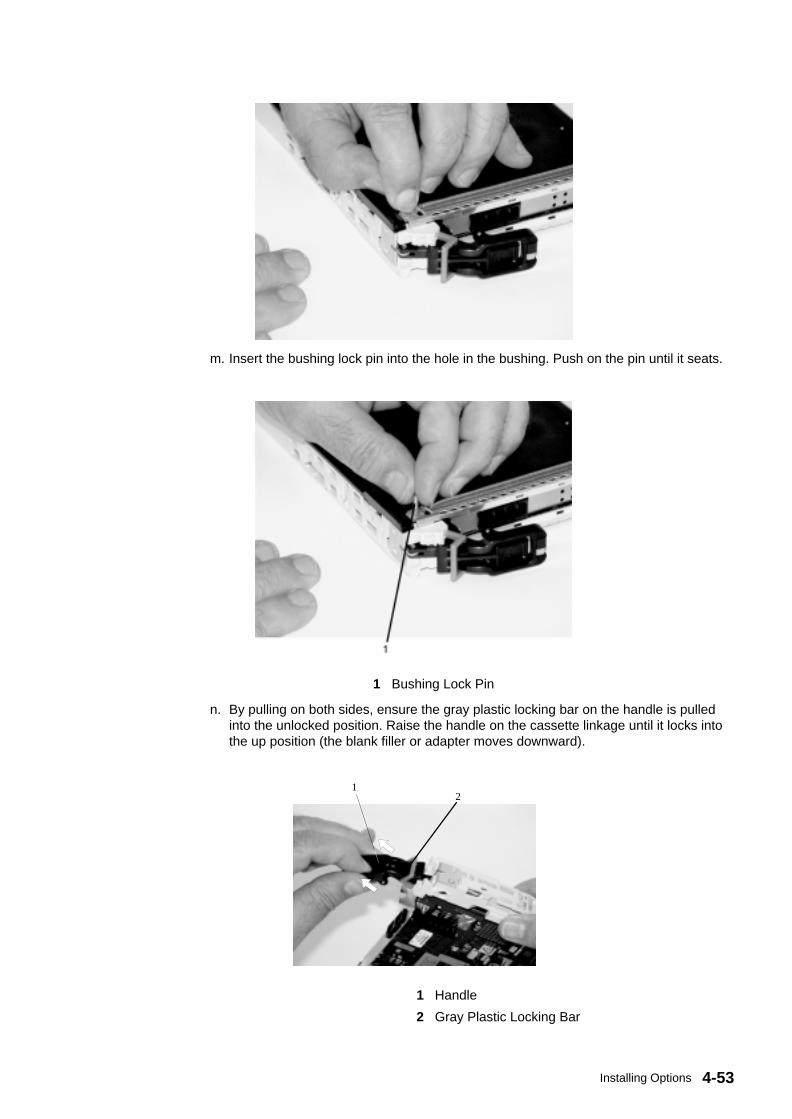
4-53Installing Options
m. Insert the bushing lock pin into the hole in the bushing. Push on the pin until it seats.
1 Bushing Lock Pin
n. By pulling on both sides, ensure the gray plastic locking bar on the handle is pulledinto the unlocked position. Raise the handle on the cassette linkage until it locks intothe up position (the blank filler or adapter moves downward).
12
1 Handle
2 Gray Plastic Locking Bar
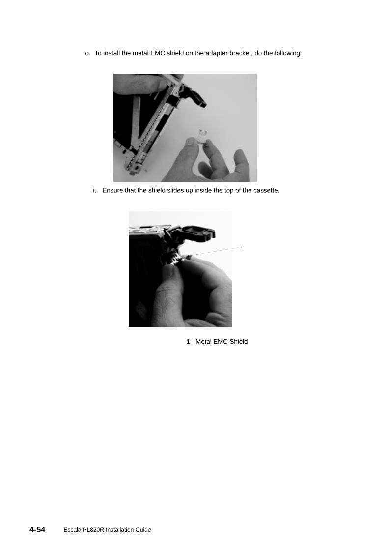
4-54 Escala PL820R Installation Guide
o. To install the metal EMC shield on the adapter bracket, do the following:
i. Ensure that the shield slides up inside the top of the cassette.
1
1 Metal EMC Shield
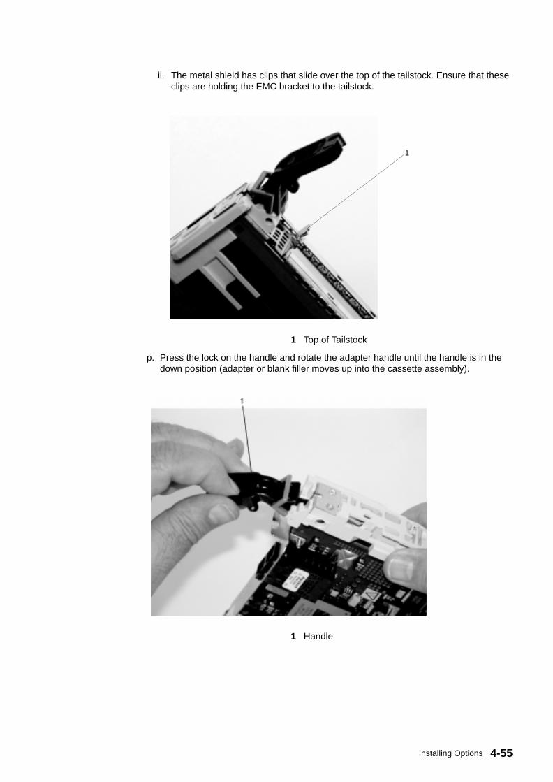
4-55Installing Options
ii. The metal shield has clips that slide over the top of the tailstock. Ensure that theseclips are holding the EMC bracket to the tailstock.
1
1 Top of Tailstock
p. Press the lock on the handle and rotate the adapter handle until the handle is in thedown position (adapter or blank filler moves up into the cassette assembly).
1 Handle
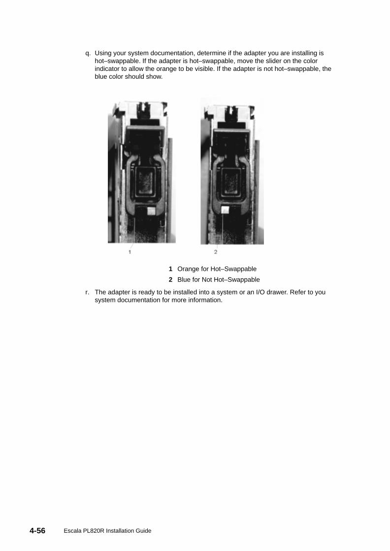
4-56 Escala PL820R Installation Guide
q. Using your system documentation, determine if the adapter you are installing ishot–swappable. If the adapter is hot–swappable, move the slider on the colorindicator to allow the orange to be visible. If the adapter is not hot–swappable, theblue color should show.
1 Orange for Hot–Swappable
2 Blue for Not Hot–Swappable
r. The adapter is ready to be installed into a system or an I/O drawer. Refer to yousystem documentation for more information.

4-57Installing Options
Replacing a Hot–Pluggable PCI AdapterAttention: The Linux operating system does not support some hot–pluggable procedures.Also, Linux does not support hot–plugging any hot–pluggable PCI adapters or devices. Thesystem with Linux installed on one or more partitions must be shutdown and powered offbefore replacing any PCI adapter or device assigned to a Linux partition. Please follow thenon–hot–pluggable adapter or device procedures when replacing a PCI adapter or device inany partition with Linux installed.
Note: Use this procedure only when you are replacing one adapter with anidentical adapter. If you are replacing an adapter with an adapter that is notidentical to the adapter that was removed, go to Removing a Hot–PluggablePCI Adapter on page 4-13 and Installing a Hot–Pluggable PCI Adapter onpage 4-12.
To replace an adapter, do the following:
1. Determine the slot from which you are removing the adapter.
2. Ensure that any processes or applications that might use the adapter are stopped.
Note: Removing a hot–pluggable PCI adapter requires the systemadministrator to take the PCI adapter offline before performing any PCIadapter hot–plug procedures. Before taking an adapter offline, thedevices attached to the adapter must also be taken offline. This actionprevents a service representative or user from causing an unexpectedoutage for system users.
For more information on taking the PCI adapter online, see the AIXoperating system documentation.
3. Log in as root user, if the system is a partitioned system, log in as root user on thepartition that has the adapter assigned to it.
4. At the command line, type smitty .
5. Select Devices .
6. Select PCI Hot Plug Manager .
7. Select Unconfigure a Device and press Enter.
8. Press F4 to display the Device Names menu.
9. From the menu, select the adapter that you are removing.
10.Answer YES to Keep Definition . Press Enter.
11.The ARE YOU SURE screen displays. Press Enter to verify the information. Successfulunconfiguration is indicated by the OK message displayed next to the Command field atthe top of the screen.
12.Press F3 to return to the PCI Hot–Plug Manager menu.
13.Select Replace/Remove a PCI Hot–Plug Adapter and press Enter. TheReplace/Remove a PCI Hot–Plug Adapter menu displays.
14.Move the cursor to select the adapter that you are removing and press Enter.
15.Press the Tab key until the entry field displays the replace operation, and press Enter.Follow the instructions that display on the screen until you are instructed to remove theadapter.
16.When you are instructed to remove the adapter from the adapter slot, disconnect anycables that are connected to the adapter being removed.
17.Press the center of the handle of the PCI adapter cassette to release the latch, and lowerthe handle completely.
18.When the handle is completely lowered, push the gray locking cross bar.
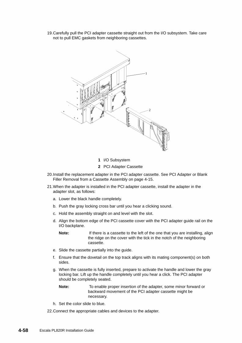
4-58 Escala PL820R Installation Guide
19.Carefully pull the PCI adapter cassette straight out from the I/O subsystem. Take carenot to pull EMC gaskets from neighboring cassettes.
1
2
1 I/O Subsystem
2 PCI Adapter Cassette
20.Install the replacement adapter in the PCI adapter cassette. See PCI Adapter or BlankFiller Removal from a Cassette Assembly on page 4-15.
21.When the adapter is installed in the PCI adapter cassette, install the adapter in theadapter slot, as follows:
a. Lower the black handle completely.
b. Push the gray locking cross bar until you hear a clicking sound.
c. Hold the assembly straight on and level with the slot.
d. Align the bottom edge of the PCI cassette cover with the PCI adapter guide rail on theI/O backplane.
Note: If there is a cassette to the left of the one that you are installing, alignthe ridge on the cover with the tick in the notch of the neighboringcassette.
e. Slide the cassette partially into the guide.
f. Ensure that the dovetail on the top track aligns with its mating component(s) on bothsides.
g. When the cassette is fully inserted, prepare to activate the handle and lower the graylocking bar. Lift up the handle completely until you hear a click. The PCI adaptershould be completely seated.
Note: To enable proper insertion of the adapter, some minor forward orbackward movement of the PCI adapter cassette might benecessary.
h. Set the color slide to blue.
22.Connect the appropriate cables and devices to the adapter.

4-59Installing Options
23.Continue to follow the screen instructions until you receive a message that thereplacement is successful. Successful replacement is indicated by the OK messagedisplayed next to the Command field at the top of the screen.
24.Press the F3 key to return to the PCI Hot–Plug Manager menu.
25.Select Install/Configure Devices Added After IPL and press Enter. Follow theinstructions on the screen. Successful replacement is indicated by the OK messagedisplayed next to the Command field at the top of the screen.
26.Press F10 to exit the Hot–Plug Manager.
27.Install any covers that you removed earlier, and return the system to the normaloperations.

4-60 Escala PL820R Installation Guide

A-1Communication Statements
Appendix A. Communications Statements
The following statement applies to this product. The statement for other products intendedfor use with this product appears in their accompanying documentation.
Federal Communications Commission (FCC) StatementNote: This equipment has been tested and found to comply with the limits for a
Class A digital device, pursuant to Part 15 of the FCC Rules. These limitsare designed to provide reasonable protection against harmful interferencewhen the equipment is operated in a commercial environment. Thisequipment generates, uses, and can radiate radio frequency energy and, ifnot installed and used in accordance with the instruction manual, maycause harmful interference to radio communications. Operation of thisequipment in a residential area is likely to cause harmful interference inwhich case the user will be required to correct the interference at his ownexpense.
Properly shielded and grounded cables and connectors must be used in order to meet FCCemission limits. Neither the provider nor the manufacturer is responsible for any radio ortelevision interference caused by using other than recommended cables and connectors orby unauthorized changes or modifications to this equipment. Unauthorized changes ormodifications could void the user’s authority to operate the equipment.
This device complies with Part 15 of the FCC Rules. Operation is subject to the followingtwo conditions: (1) this device may not cause harmful interference, and (2) this device mustaccept any interference received, including interference that may cause undesiredoperation.
European Union (EU) StatementThis product is in conformity with the protection requirements of EU Council Directive89/336/EEC on the approximation of the laws of the Member States relating toelectromagnetic compatibility. The manufacturer cannot accept responsibility for any failureto satisfy the protection requirements resulting from a non–recommended modification ofthe product, including the fitting of option cards supplied by third parties. Consult with yourdealer or sales representative for details on your specific hardware.
This product has been tested and found to comply with the limits for Class A InformationTechnology Equipment according to CISPR 22 / European Standard EN 55022. The limitsfor Class A equipment were derived for commercial and industrial environments to providereasonable protection against interference with licensed communication equipment.
Attention: This is a Class A product. In a domestic environment this product may causeradio interference in which case the user may be required to take adequate measures.
International Electrotechnical Commission (IEC) StatementThis product has been designed and built to comply with IEC 60950.

A-2 Escala PL820R Installation Guide
United Kingdom Telecommunications Safety RequirementsThis equipment is manufactured to the International Safety Standard EN60950 and as suchis approved in the UK under the General Approval Number NS/G/1234/J/100003 for indirectconnection to the public telecommunication network.
The network adapter interfaces housed within this equipment are approved separately, eachone having its own independent approval number. These interface adapters, supplied by themanufacturer, do not use or contain excessive voltages. An excessive voltage is one whichexceeds 70.7 V peak ac or 120 V dc. They interface with this equipment using Safe ExtraLow Voltages only. In order to maintain the separate (independent) approval of themanufacturer’s adapters, it is essential that other optional cards, not supplied by themanufacturer, do not use main voltages or any other excessive voltages. Seek advice froma competent engineer before installing other adapters not supplied by the manufacturer.
Avis de conformité aux normes du ministère desCommunications du Canada
Cet appareil numérique de la classe A respecte toutes les exigences du Réglement sur lematériel brouilleur du Canada.
Canadian Department of Communications ComplianceStatement
This Class A digital apparatus meets the requirements of the CanadianInterference–Causing Equipment Regulations.
VCCI Statement
Figure 1.a4avcci1
The following is a summary of the VCCI Japanese statement in the box above.
This is a Class A product based on the standard of the Voluntary Control Council forInterference by Information Technology Equipment (VCCI). If this equipment is used in adomestic environment, radio disturbance may arise. When such trouble occurs, the usermay be required to take corrective actions.

A-3Communication Statements
Electromagnetic Interference (EMI) Statement – Taiwan
Figure 2.a4ataiw1
The following is a summary of the EMI Taiwan statement above.
Warning: This is a Class A product. In a domestic environment this product may cause radiointerference in which case the user will be required to take adequate measures.
Radio Protection for GermanyDieses Gerät ist berechtigt in Übereinstimmung mit Dem deutschen EMVG vom 9.Nov.92das EG–Konformitätszeichen zu führen.
Der Aussteller der Konformitätserklärung ist die Germany.
Dieses Gerät erfüllt die Bedingungen der EN 55022 Klasse A. Für diese von Geräten giltfolgende Bestimmung nach dem EMVG:
Geräte dürfen an Orten, für die sie nicht ausreichend entstört sind, nur mit besondererGenehmigung des Bundesministers für Post und Telekommunikation oder desBundesamtes für Post und Telekommunikation betrieben werden. Die Genehmigung wirderteilt, wenn keine elektromagnetischen Störungen zu erwarten sind.
(Auszug aus dem EMVG vom 9.Nov.92, Para.3, Abs.4)
Hinweis
Dieses Genehmigungsverfahren ist von der Deutschen Bundespost noch nicht veröffentlichtworden.

A-4 Escala PL820R Installation Guide

B-1Environmental Notices
Appendix B. Environmental Notices
Product Recycling and DisposalComponents of the system unit, such as structural parts and circuit boards, can be recycledwhere recycling facilities exist. Companies are available to disassemble, reutilize, recycle, ordispose of electronic products. Contact your account representative for more information.This system unit contains parts such as circuit boards, cables, electromagnetic compatibilitygaskets and connectors which may contain lead and copper/beryllium alloys that requirespecial handling and disposal at end of life. Before this unit is disposed, these materialsmust be removed and recycled or discarded according to applicable regulations. This bookcontains specific information on each battery type where applicable. This product maycontain a sealed lead acid battery(s) or nickel–cadmium battery(s). The battery(s) must berecycled or disposed of properly. Recycling facilities may not be available in your area.
For information on reuse, recycling or proper battery disposal procedures, contact yoursales representative or local waste disposal facility.

B-2 Escala PL820R Installation Guide
Acoustical Noise EmissionsThe equivalent continuous A–weighted sound pressure level at workstations (emissionsound pressure level at the 1–meter bystander positions) does not exceed 70 dB(A).
Der Geräuschpegel der Einheit ist kleiner oder gleich 70 db(A).
Declared Acoustical Noise Emissions
Acoustical Characteristic
ProductConfiguration
Declared A–Weighted SoundPower Level, L WAd (B)
Declared A–Weighted SoundPressure Level, L pAm (dB)g
Operating Idle Operating Idle
ProcessorSubsystem
6.1 5 6.1 5 44 6 44 6
Notes:
1. Noise levels cited are for the typical configuration (A–Frame: Bulk Power, CEC cage,battery option, media drawer, and two I/O drawers).
2. The 0.6–B (6–dB) reduction in noise emission levels with the acoustical rear doorcorresponds to a factor of 4 reduction. That is, the noise level of a single A–Frame withSlimline covers is about the same as the noise level of four A–Frames with acousticalcovers.
3. L WAd is the upper–limit A–weighted sound power level; LpAm is the mean A–weightedsound pressure level at the 1–meter bystander positions; 1 B = 10 dB.
4. All measurements made in conformance with ISO 7779 and declared in conformancewith ISO 9296.

C-1PCI Adapters Placement Reference
Appendix C. PCI Adapter Placement Reference
This system is designed for customers to install adapters. Use this guide to determine ifthere are specific slot requirements for adapters that you may be installing.
Some adapters must be placed in specific system unit slots to function correctly at optimumperformance. Use the information in the following sections of this chapter to determinewhere to install adapters in your system unit.
Logical Partition (LPAR) ConsiderationsPlace redundant devices in separate I/O drawers for best availability performance. Placenon–redundant devices in the same I/O drawer. If you place non–redundant devices in onedrawer, the system is less exposed to other–drawer failures.
Some devices do not have enhanced error handling (EEH) capabilities built in to their devicedrivers. If these devices fail, the PCI Host Bridge (PHB) in which they are placed will beaffected. If the I/O subsystem encounters a severe error, all slots in the PHB are alsoaffected. To clear this condition, you may reboot the system. In addition, it is also possible toremove the failed PCI slots on an affected PHB from the partition profile or profiles thatinclude these PCI slots, and reboot the partition or partitions that terminated at the time ofthe error.
To avoid PHB errors related to non–EEH adapters, it is strongly recommended that if anon–EEH adapter is used, then all slots on that PHB should be assigned to a single LPAR.Refer to the tables in this chapter for additional information about LPAR (logical partitioning)considerations.
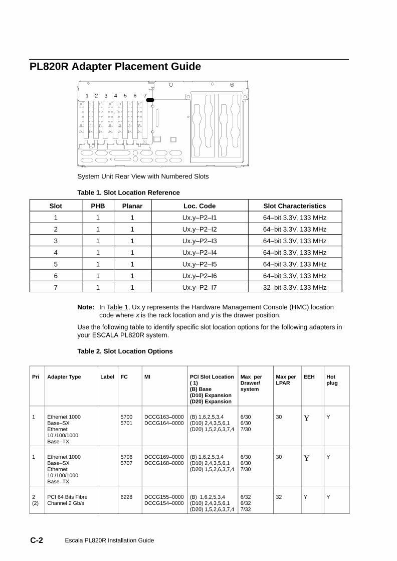
C-2 Escala PL820R Installation Guide
PL820R Adapter Placement Guide
1 2 3 4 5 6 7
System Unit Rear View with Numbered Slots
Table 1. Slot Location Reference
Slot PHB Planar Loc. Code Slot Characteristics
1 1 1 Ux.y–P2–I1 64–bit 3.3V, 133 MHz
2 1 1 Ux.y–P2–I2 64–bit 3.3V, 133 MHz
3 1 1 Ux.y–P2–I3 64–bit 3.3V, 133 MHz
4 1 1 Ux.y–P2–I4 64–bit 3.3V, 133 MHz
5 1 1 Ux.y–P2–I5 64–bit 3.3V, 133 MHz
6 1 1 Ux.y–P2–I6 64–bit 3.3V, 133 MHz
7 1 1 Ux.y–P2–I7 32–bit 3.3V, 133 MHz
Note: In Table 1, Ux.y represents the Hardware Management Console (HMC) locationcode where x is the rack location and y is the drawer position.
Use the following table to identify specific slot location options for the following adapters inyour ESCALA PL820R system.
Table 2. Slot Location Options
Pri Adapter Type Label FC MI PCI Slot Location( 1)(B) Base(D10) Expansion(D20) Expansion
Max perDrawer/system
Max perLPAR
EEH Hotplug
1 Ethernet 1000Base–SXEthernet10 /100/1000Base–TX
57005701
DCCG163–0000DCCG164–0000
(B) 1,6,2,5,3,4(D10) 2,4,3,5,6,1(D20) 1,5,2,6,3,7,4
6/306/307/30
30 Y Y
1 Ethernet 1000Base–SXEthernet10 /100/1000Base–TX
57065707
DCCG169–0000DCCG168–0000
(B) 1,6,2,5,3,4(D10) 2,4,3,5,6,1(D20) 1,5,2,6,3,7,4
6/306/307/30
30 Y Y
2(2)
PCI 64 Bits FibreChannel 2 Gb/s
6228 DCCG155–0000DCCG154–0000
(B) 1,6,2,5,3,4(D10) 2,4,3,5,6,1(D20) 1,5,2,6,3,7,4
6/326/327/32
32 Y Y
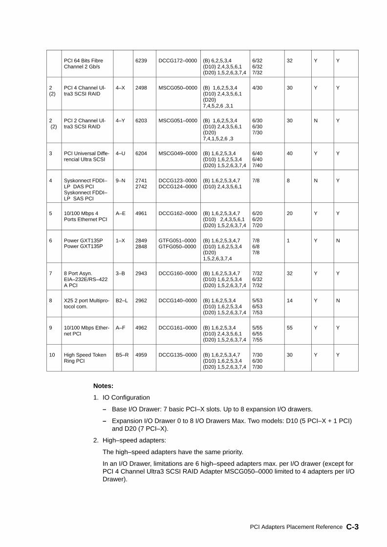
C-3PCI Adapters Placement Reference
PCI 64 Bits FibreChannel 2 Gb/s
6239 DCCG172–0000 (B) 6,2,5,3,4(D10) 2,4,3,5,6,1(D20) 1,5,2,6,3,7,4
6/326/327/32
32 Y Y
2(2)
PCI 4 Channel Ul-tra3 SCSI RAID
4–X 2498 MSCG050–0000 (B) 1,6,2,5,3,4(D10) 2,4,3,5,6,1(D20)7,4,5,2,6 ,3,1
4/30 30 Y Y
2 (2)
PCI 2 Channel Ul-tra3 SCSI RAID
4–Y 6203 MSCG051–0000 (B) 1,6,2,5,3,4(D10) 2,4,3,5,6,1(D20)7,4,1,5,2,6 ,3
6/306/307/30
30 N Y
3 PCI Universal Diffe-rencial Ultra SCSI
4–U 6204 MSCG049–0000 (B) 1,6,2,5,3,4(D10) 1,6,2,5,3,4(D20) 1,5,2,6,3,7,4
6/406/407/40
40 Y Y
4 Syskonnect FDDI–LP DAS PCISyskonnect FDDI–LP SAS PCI
9–N 27412742
DCCG123–0000DCCG124–0000
(B) 1,6,2,5,3,4,7(D10) 2,4,3,5,6,1
7/8 8 N Y
5 10/100 Mbps 4Ports Ethernet PCI
A–E 4961 DCCG162–0000 (B) 1,6,2,5,3,4,7(D10) 2,4,3,5,6,1(D20) 1,5,2,6,3,7,4
6/206/207/20
20 Y Y
6 Power GXT135PPower GXT135P
1–X 28492848
GTFG051–0000GTFG050–0000
(B) 1,6,2,5,3,4,7(D10) 1,6,2,5,3,4(D20)1,5,2,6,3,7,4
7/86/87/8
1 Y N
7 8 Port Asyn.EIA–232E/RS–422A PCI
3–B 2943 DCCG160–0000 (B) 1,6,2,5,3,4,7(D10) 1,6,2,5,3,4(D20) 1,5,2,6,3,7,4
7/326/327/32
32 Y Y
8 X25 2 port Multipro-tocol com.
B2–L 2962 DCCG140–0000 (B) 1,6,2,5,3,4(D10) 1,6,2,5,3,4(D20) 1,5,2,6,3,7,4
5/536/537/53
14 Y N
9 10/100 Mbps Ether-net PCI
A–F 4962 DCCG161–0000 (B) 1,6,2,5,3,4(D10) 2,4,3,5,6,1(D20) 1,5,2,6,3,7,4
5/556/557/55
55 Y Y
10 High Speed TokenRing PCI
B5–R 4959 DCCG135–0000 (B) 1,6,2,5,3,4,7(D10) 1,6,2,5,3,4(D20) 1,5,2,6,3,7,4
7/306/307/30
30 Y Y
Notes:
1. IO Configuration
– Base I/O Drawer: 7 basic PCI–X slots. Up to 8 expansion I/O drawers.
– Expansion I/O Drawer 0 to 8 I/O Drawers Max. Two models: D10 (5 PCI–X + 1 PCI)and D20 (7 PCI–X).
2. High–speed adapters:
The high–speed adapters have the same priority.
In an I/O Drawer, limitations are 6 high–speed adapters max. per I/O drawer (except forPCI 4 Channel Ultra3 SCSI RAID Adapter MSCG050–0000 limited to 4 adapters per I/ODrawer).

C-4 Escala PL820R Installation Guide
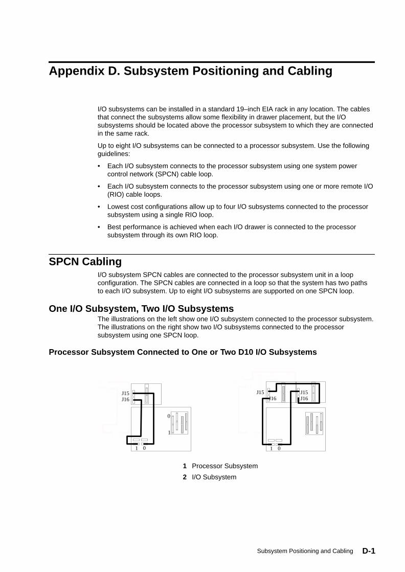
D-1Subsystem Positioning and Cabling
Appendix D. Subsystem Positioning and Cabling
I/O subsystems can be installed in a standard 19–inch EIA rack in any location. The cablesthat connect the subsystems allow some flexibility in drawer placement, but the I/Osubsystems should be located above the processor subsystem to which they are connectedin the same rack.
Up to eight I/O subsystems can be connected to a processor subsystem. Use the followingguidelines:
• Each I/O subsystem connects to the processor subsystem using one system powercontrol network (SPCN) cable loop.
• Each I/O subsystem connects to the processor subsystem using one or more remote I/O(RIO) cable loops.
• Lowest cost configurations allow up to four I/O subsystems connected to the processorsubsystem using a single RIO loop.
• Best performance is achieved when each I/O drawer is connected to the processorsubsystem through its own RIO loop.
SPCN CablingI/O subsystem SPCN cables are connected to the processor subsystem unit in a loopconfiguration. The SPCN cables are connected in a loop so that the system has two pathsto each I/O subsystem. Up to eight I/O subsystems are supported on one SPCN loop.
One I/O Subsystem, Two I/O SubsystemsThe illustrations on the left show one I/O subsystem connected to the processor subsystem.The illustrations on the right show two I/O subsystems connected to the processorsubsystem using one SPCN loop.
Processor Subsystem Connected to One or Two D10 I/O Subsystems
0
1
1
J15J16
0 1
J15 J16
J15J16
0
0
1
1
J15J16
0 1
J15 J16
J15J16
0
1 Processor Subsystem
2 I/O Subsystem
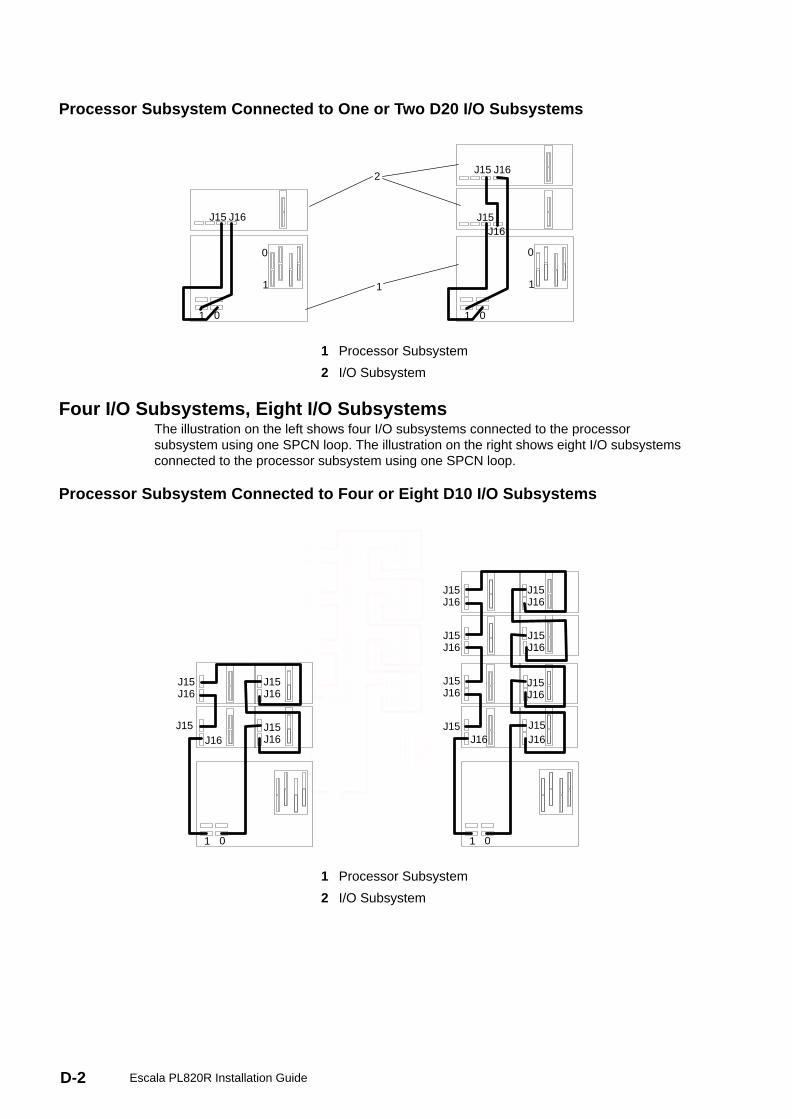
D-2 Escala PL820R Installation Guide
Processor Subsystem Connected to One or Two D20 I/O Subsystems
0 0
1 1
1 0 1 0
1
2J15
J15 J15
J16
J16J16
1 Processor Subsystem
2 I/O Subsystem
Four I/O Subsystems, Eight I/O SubsystemsThe illustration on the left shows four I/O subsystems connected to the processorsubsystem using one SPCN loop. The illustration on the right shows eight I/O subsystemsconnected to the processor subsystem using one SPCN loop.
Processor Subsystem Connected to Four or Eight D10 I/O Subsystems
1
J15J16
J15J16
J15J16
J15J16
J15J16
J15J16
J15 J15J16 J16
0
1
J15J16
J15J16
J15J16
J15J16
J15J16
J15J16
J15J15 J15J16J16 J16
01
J15J16
J15J16
J15J16
0
1 Processor Subsystem
2 I/O Subsystem
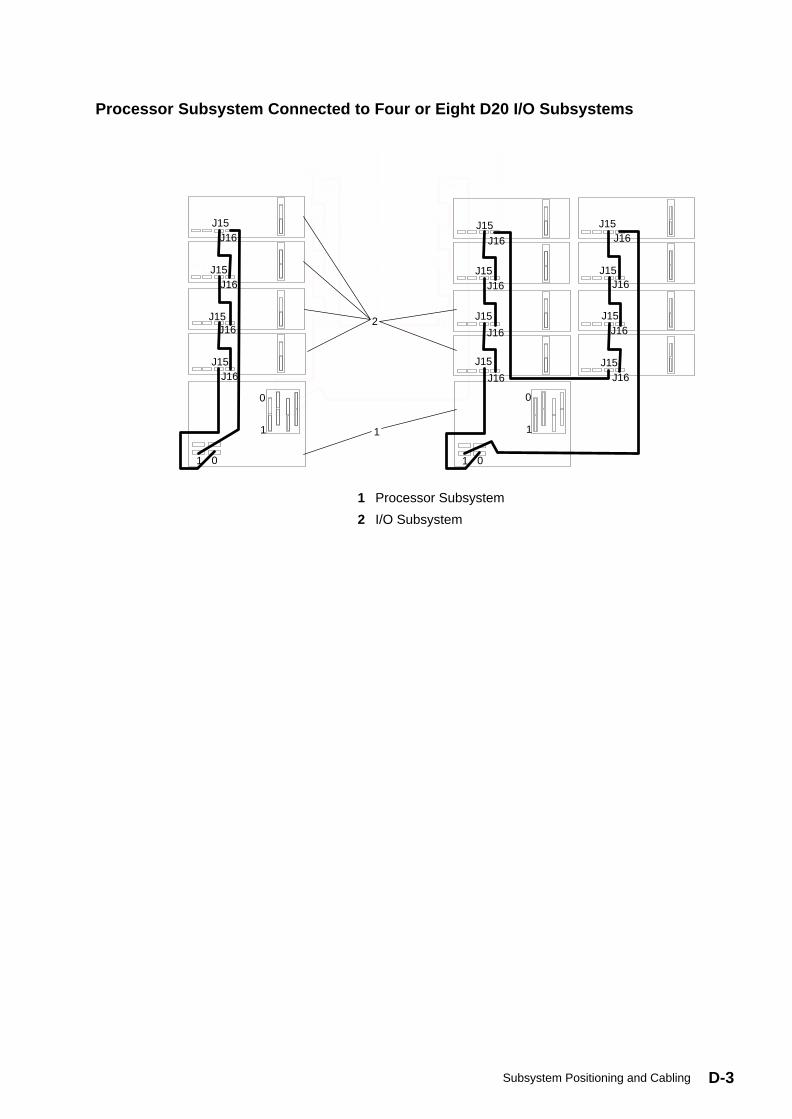
D-3Subsystem Positioning and Cabling
Processor Subsystem Connected to Four or Eight D20 I/O Subsystems
J16
J16
J16
J16
J16J15
J15
J15
J15
J15
J15
J15
J15
J16
J16
J16
0
1
1 0
1
2
0
J15
J15
J15
J15
J16
J16
J16
J16
J16
J16
J16
J16J15
J15
J15
J15
J15
J15
J15
J15
J16
J16
J16
J16
0
1 1
1 0 1 0
1
2
1 Processor Subsystem
2 I/O Subsystem

D-4 Escala PL820R Installation Guide
RIO CablingI/O subsystems are connected to the processor subsystem through remote I/O (RIO) cableloops. The cable loops are connected to ports that are available from the rear of theprocessor subsystem. The RIO cables are connected in loops so that the system has twopaths to each I/O subsystem when more than one I/O drawer is in a loop.
If only one I/O subsystem is in a RIO loop and both the processor subsystem and the I/Osubsystem are RIO–G capable, the RIO–G cables are used as one two–cable path to theI/O subsystem. In this cable configuration, the data rate is increased by a factor of 2.
• A maximum of eight D10 drawers are supported on one processor subsystem.
• A maximum of eight D20 I/O drawers are supported on one processor subsystem.
• If both Model D10 and Model D20 I/O drawers are connected to the same processorsubsystem, the total number of I/O subsystems supported is eight.
• The maximum number of I/O subsystems supported on one RIO loop is four.
• The Model D10 and Model D20 I/O drawers must be on separate RIO loops.
• The Model D10 and Model D10–G can share one RIO loop.
• The Model D20 and Model D20–G can share one RIO loop.
The system can have up to four RIO loops. A total of eight I/O drawers can be connected tothe processor subsystem in a variety of cabling configurations. For optimum performance,connect the RIO loops in a configuration that spreads multiple I/O drawers across as manyRIO loops as possible. A dedicated RIO loop for each I/O drawer can provide highestperformance. Some examples of valid cabling examples follow.
One I/O Subsystem or Two I/O SubsystemsThe illustrations on the left shows one I/O subsystem drawer connected to the processorsubsystem. The illustrations on the right show two I/O subsystem drawers connected to thesystem unit using one RIO loop.
Processor Subsystem Connected to One or Two D10 I/O Subsystems
A0
A1
1
00
1
1A0 A0
A1 A1
0
1 1
00
1
1
2
1 Processor Subsystem
2 I/O Subsystem
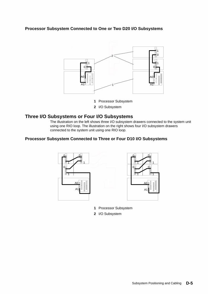
D-5Subsystem Positioning and Cabling
Processor Subsystem Connected to One or Two D20 I/O Subsystems
0
1
01
1
2
A0
A1
0
0
1
1
01
1
2
A0 A0
A1 A1
1 Processor Subsystem
2 I/O Subsystem
Three I/O Subsystems or Four I/O SubsystemsThe illustration on the left shows three I/O subsystem drawers connected to the system unitusing one RIO loop. The illustration on the right shows four I/O subsystem drawersconnected to the system unit using one RIO loop.
Processor Subsystem Connected to Three or Four D10 I/O Subsystems
0 0
0 0
0 0
0
1 1
1 1
1 1
1
A0 A0
A1 A1
1 Processor Subsystem
2 I/O Subsystem
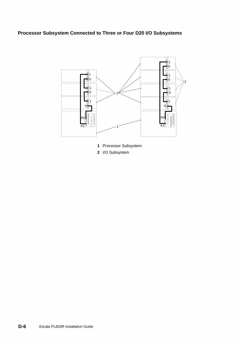
D-6 Escala PL820R Installation Guide
Processor Subsystem Connected to Three or Four D20 I/O Subsystems
0
0
1
1
0
0
1
1
2
1
2
A0
A1
0
00
1
11
00
00
11
11
2
1
2
A0 A0
A1 A1
1 Processor Subsystem
2 I/O Subsystem
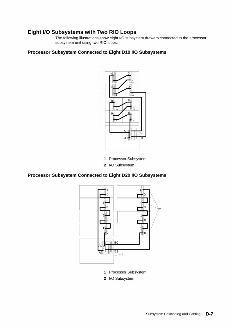
D-7Subsystem Positioning and Cabling
Eight I/O Subsystems with Two RIO LoopsThe following illustrations show eight I/O subsystem drawers connected to the processorsubsystem unit using two RIO loops.
Processor Subsystem Connected to Eight D10 I/O Subsystems
0
0
0
0
1
1
1
1
0
0
0
0
1
1
1
1
A0B0
B1A1
0
0
0
0
1
1
1
1
0
0
0
0
1
1
1
1
A0B0
B1A1
1 Processor Subsystem
2 I/O Subsystem
Processor Subsystem Connected to Eight D20 I/O Subsystems
0 0
0 0
1 1
1 1
0 0
0 0
1 1
1 1
2
1
A0B0
A1 B1
1 Processor Subsystem
2 I/O Subsystem
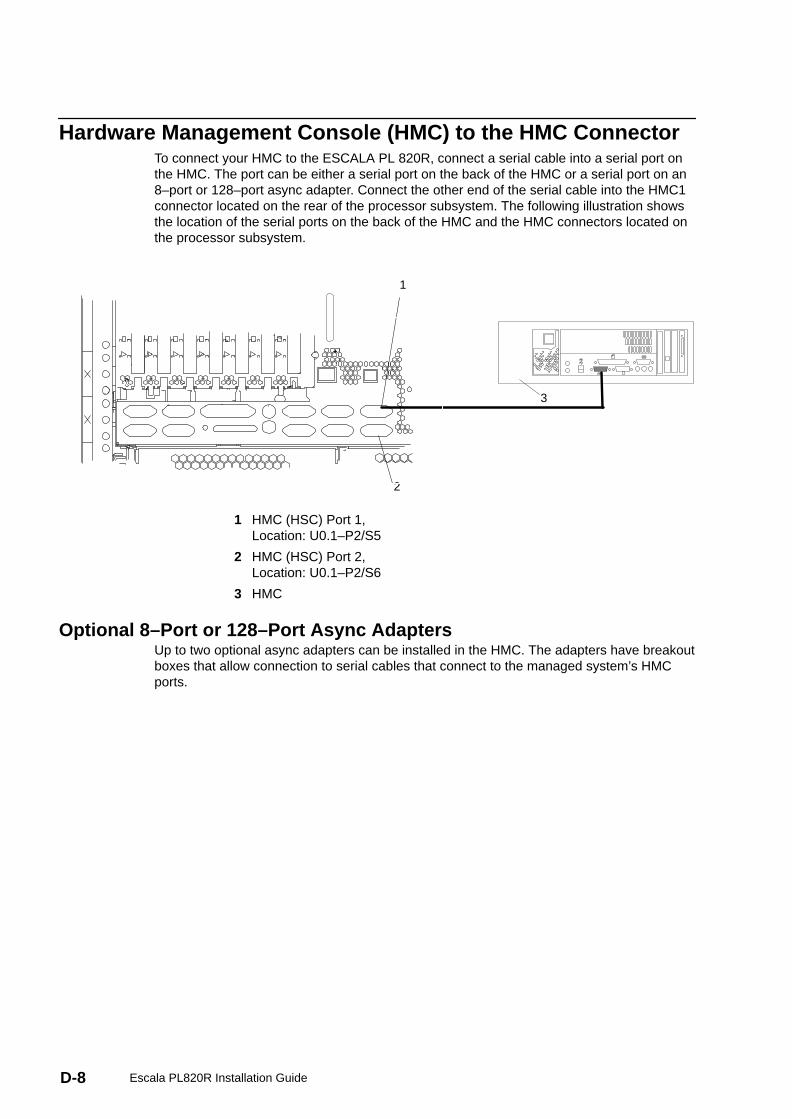
D-8 Escala PL820R Installation Guide
Hardware Management Console (HMC) to the HMC ConnectorTo connect your HMC to the ESCALA PL 820R, connect a serial cable into a serial port onthe HMC. The port can be either a serial port on the back of the HMC or a serial port on an8–port or 128–port async adapter. Connect the other end of the serial cable into the HMC1connector located on the rear of the processor subsystem. The following illustration showsthe location of the serial ports on the back of the HMC and the HMC connectors located onthe processor subsystem.
1
2
3
1 HMC (HSC) Port 1,Location: U0.1–P2/S5
2 HMC (HSC) Port 2,Location: U0.1–P2/S6
3 HMC
Optional 8–Port or 128–Port Async AdaptersUp to two optional async adapters can be installed in the HMC. The adapters have breakoutboxes that allow connection to serial cables that connect to the managed system’s HMCports.
E-1Service Processor Setup and Test
Appendix E. Service Processor Setup and Test
Attention: This procedure applies to modems attached to the serial ports (S1 and S2) onthe system drawer. It does not affect the operation of the modem attached to the HardwareManagement Console (HMC).
The call–out function is normally handled by the service focal point running on the HMC.
For your convenience, an example of a basic service processor setup checklist is includedhere. Your setup may include more or fewer of the available features, so you can adjust thischecklist for your own application.
Note: Call–out and surveillance are disabled in partitioned systems.
Service Processor Setup Checklist1. Shut down the managed system, wait for the ”OK” in the physical operator panel.
2. Open a virtual terminal on the HMC.
3. Bring up the service processor menus.
4. Set the system name.
5. Enable Surveillance.
6. Configure call–in/call–out.
7. Exit the service processor menus.
8. Remove all power by removing the power cords from both power supplies in the rear ofthe processor subsystem.
9. Attach modems (if needed).
10.Apply power by reconnecting the power cords to both power supplies in the rear of theprocessor subsystem.
Attention: Make sure that system power remains off.
11.Test both of the following:
– Call–In, page Testing Call–In on page E-2
– Call–Out, page Testing Call–Out on page E-2
Your service processor is now ready for use.
Testing the SetupThis section contains sample testing procedures to help ensure your setup is working.
These tests include communicating with the server operating system. Before you start,ensure that the necessary serial port(s) is configured. If you need assistance, refer to SerialPort Configuration on page E-2.
The server should be powered off as a result of the Service Processor Setup Checklist onpage E-1.
E-2 Escala PL820R Installation Guide
Testing Call–In1. Go to your remote terminal and call in to your server. Your server answers and offers you
the service processor Main Menu after requesting your privileged access password.
2. Select System Power Control .
3. Select Power–On System .
When you are asked if you wish to continue powering on the system, type Y.
4. After the system firmware and operating system have initialized the server, the loginprompt displays at your remote terminal if you set up seamless modem transfer. Thismay take several minutes. When the login prompt displays, you have successfully calledthe service processor.
5. Type logout to disconnect from the operating system. The message No Carrierdisplays on your remote terminal.
6. Call your server again. The operating system answers and offers you the login prompt. Ifthese tests are successful, call–in is working.
7. Log in and type shutdown –F to shut down your server.
8. The message No Carrier displays on your remote terminal.
Testing Call–OutDuring the setup, you entered your phone numbers for the pager and customer voice (referto the ESCALA PL 820R Service Guide for more information. These numbers are used forthis test.
1. Your remote terminal is disconnected as a result of the Call–In test.
2. Call your server again.
3. At the service processor Main Menu, select Call–In/Call–Out Setup menu, then selectCall–Out test. This action causes a simulated error condition for the purposes of thistest.
4. After a few moments, a message displays, regarding an illegal entry. Press Enter to clearthe message and return to the main menu.
5. When your telephone rings, answer the call. You should hear the sound of a telephonebeing dialed. This is your computer trying to page you.
If this test is successful, call–out is working correctly.
Serial Port ConfigurationTo configure the serial port on an AIX system, run the following from an AIX console:
1. Log in as root user.
2. To determine if you have any serial ports already configured, type:
lsdev –Cc tty
If no serial ports are configured, none are listed. If you want to configure serial ports thatare not listed, continue with the remaining steps.
3. Identify the serial port(s) with the modem(s).
4. Type smit tty
5. Select add tty
6. Select RS232
7. Select Baud rate 9600 or higher.
8. Select login enable and set the flow control to RTS.

E-3Service Processor Setup and Test
9. Commit the selections and set up any other needed serial ports.
10.Exit SMIT.

E-4 Escala PL820R Installation Guide

F-1Firmware Updates
Appendix F. Firmware Updates
This section provides information and instructions for updating the system firmware. Youmay need to perform these steps if you are installing an option or if your supportrepresentative has requested that you update your firmware.
If you cannot download from the Web, do the following:
• If the system cannot be powered on, but the service processor menus are available, seeUpdating System Firmware From the Service Processor Menus on page F-2.
• If the service processor programming has been corrupted, the service processor willautomatically enter recovery mode when power is applied to the system.
To check the level of firmware that is currently on the system, see Determining the Level ofFirmware on the System on page F-1.
General Information on System Firmware UpdatesAll the system firmware types that can be reprogrammed are updated at the same time.They are:
• System power control network programming
• Service processor programming
• IPL programming
• Run–time abstraction services
Retain and store the latest firmware diskettes each time the firmware gets updated in theevent that the firmware becomes corrupted and must be reloaded.
Determining the Level of Firmware on the SystemThere are two forms in which the firmware level may be denoted:
• RKyymmdd, where RK = the ESCALA PL 820R’s firmware designation, yy = year, mm =month, and dd = day of the release.
• vKyymmdd, where v = version number, K = the ESCALA PL 820R’s firmwaredesignation, yy = year, mm = month and dd = day of the release.
If your system is running AIX, the platform firmware level can be determined by either of thefollowing methods:
• On the AIX command line, by typing:
lscfg –vp|grep –p Platform
A line that begins with ROM level (alterable).. displays the firmware level that iscurrently on the system.
• Looking at the top of the service processor main menu.
If the system is running Linux, the platform firmware level can be determined by any one ofthe following methods:
• If the system was installed prior to May of 2003, and has not had a firmware update inthe May 2003 time frame or later, type the following on the Linux command line:
F-2 Escala PL820R Installation Guide
/usr/sbin/ibmras/nvram ––print–vpd | grep RK
• If the system was installed in May of 2003 or later, or the system has firmware on it thatwas released in the May 2003 time frame or later, type the following on the Linuxcommand line:
/usr/sbin/ibmras/nvram ––print–vpd | grep 3K
A line similar to Alterable ROM Level RK021114 or Alterable ROM Level3K030509 displays the firmware level that is currently on the system.
• Looking at the top of the service processor menu main menu.
Updating System Firmware From the Service Processor MenusThis procedure requires a diskette drive to be installed in the system. This procedure alsorequires a set of firmware update diskettes in backup format.
The service processor menus are available while the system is powered off. As a privilegeduser, from the service processor main menu, select Service Processor Setup , then selectReprogram Flash EPROM Menu . The update process requests update diskettes asneeded.
Updating System Firmware from a NIM ServerRefer to Running Standalone Diagnostics from a Network Installation Management (NIM)Server with an HMC Attached to the System on page 2-6.
Recovery ModeContact your marketing representative for information about obtaining and installing systemfirmware update packages.
Code Action
A1FD 0000 System firmware has been corrupted and must bereflashed.
A1FD 0001 Insert update diskette 1.
A1FD 0002 Insert update diskette 2.
A1FD 0003 Insert update diskette 3.
A1FD 000n Insert update diskette n.
Notes:
1. If the wrong diskette is inserted at any time, or if the diskette is left in the drive after it hasbeen read, B1FD 001F is displayed, indicating that the wrong diskette is in the drive.
2. If B1FD 001A is displayed at any time during the process, the service processor mustbe reset by activating the pinhole reset switch on the primary drawer operator panel.

G-1System Records
Appendix G. System Records
Record the Identification NumbersRecord and retain the following information.
System Name: ____________________________
System Machine Type and SerialNumber:
____________________________
Number of I/O SubsystemsAttached:
____________________________
I/O subsystem Machine Type andSerial Numbers:
____________________________
____________________________
____________________________
____________________________
____________________________
____________________________
____________________________
The identification numbers for the system and attached I/O subsystems are located on thefront cover and on the rear of the units.
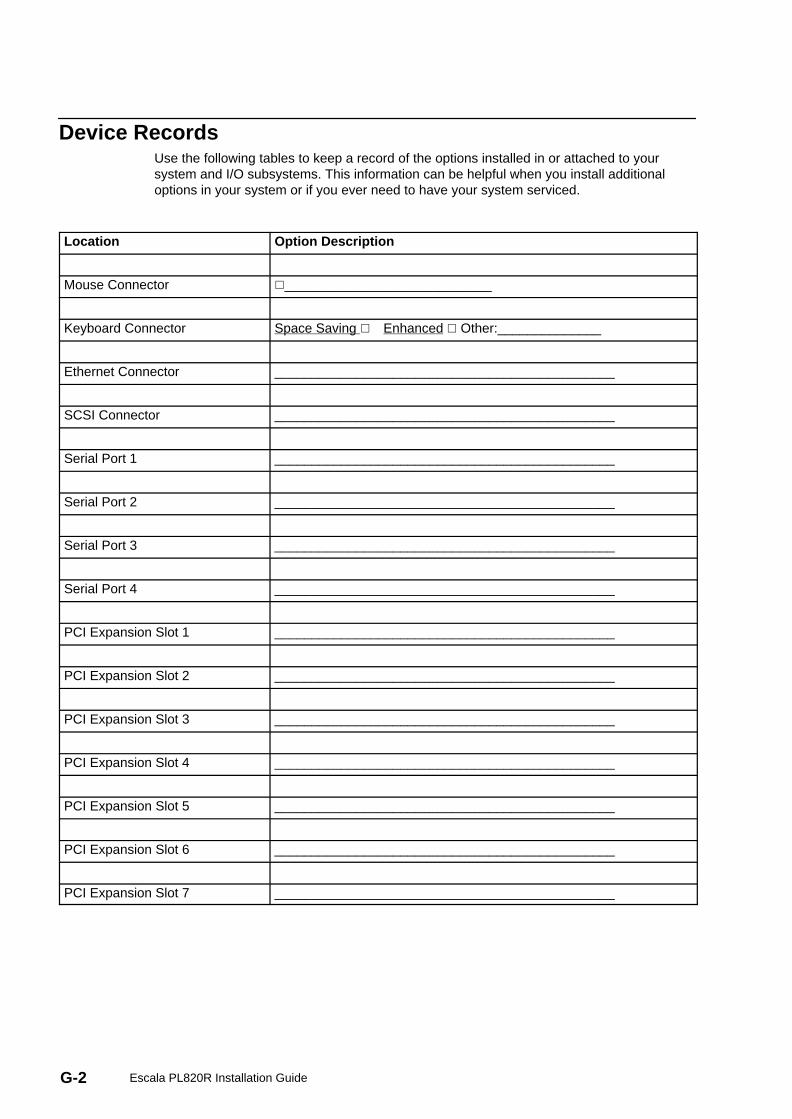
G-2 Escala PL820R Installation Guide
Device RecordsUse the following tables to keep a record of the options installed in or attached to yoursystem and I/O subsystems. This information can be helpful when you install additionaloptions in your system or if you ever need to have your system serviced.
Location Option Description
Mouse Connector �____________________________
Keyboard Connector Space Saving � Enhanced � Other:______________
Ethernet Connector ______________________________________________
SCSI Connector ______________________________________________
Serial Port 1 ______________________________________________
Serial Port 2 ______________________________________________
Serial Port 3 ______________________________________________
Serial Port 4 ______________________________________________
PCI Expansion Slot 1 ______________________________________________
PCI Expansion Slot 2 ______________________________________________
PCI Expansion Slot 3 ______________________________________________
PCI Expansion Slot 4 ______________________________________________
PCI Expansion Slot 5 ______________________________________________
PCI Expansion Slot 6 ______________________________________________
PCI Expansion Slot 7 ______________________________________________
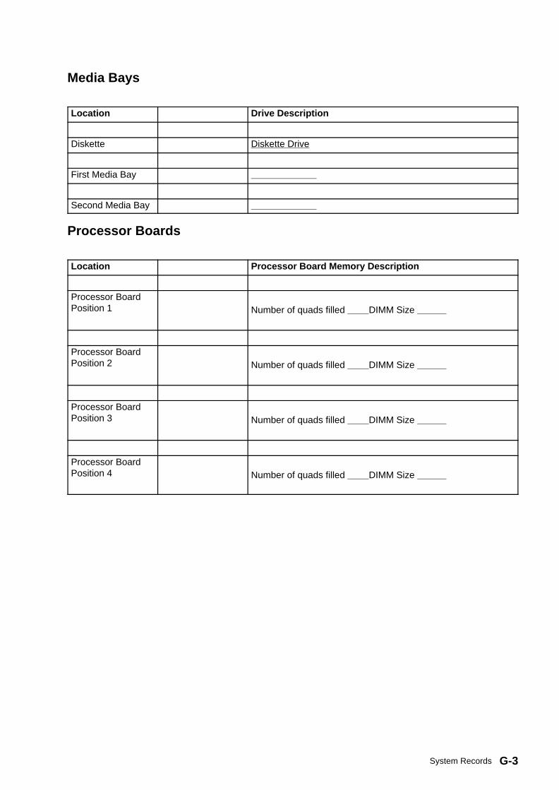
G-3System Records
Media Bays
Location Drive Description
Diskette Diskette Drive
First Media Bay
Second Media Bay
Processor Boards
Location Processor Board Memory Description
Processor BoardPosition 1 Number of quads filled DIMM Size
Processor BoardPosition 2 Number of quads filled DIMM Size
Processor BoardPosition 3 Number of quads filled DIMM Size
Processor BoardPosition 4 Number of quads filled DIMM Size
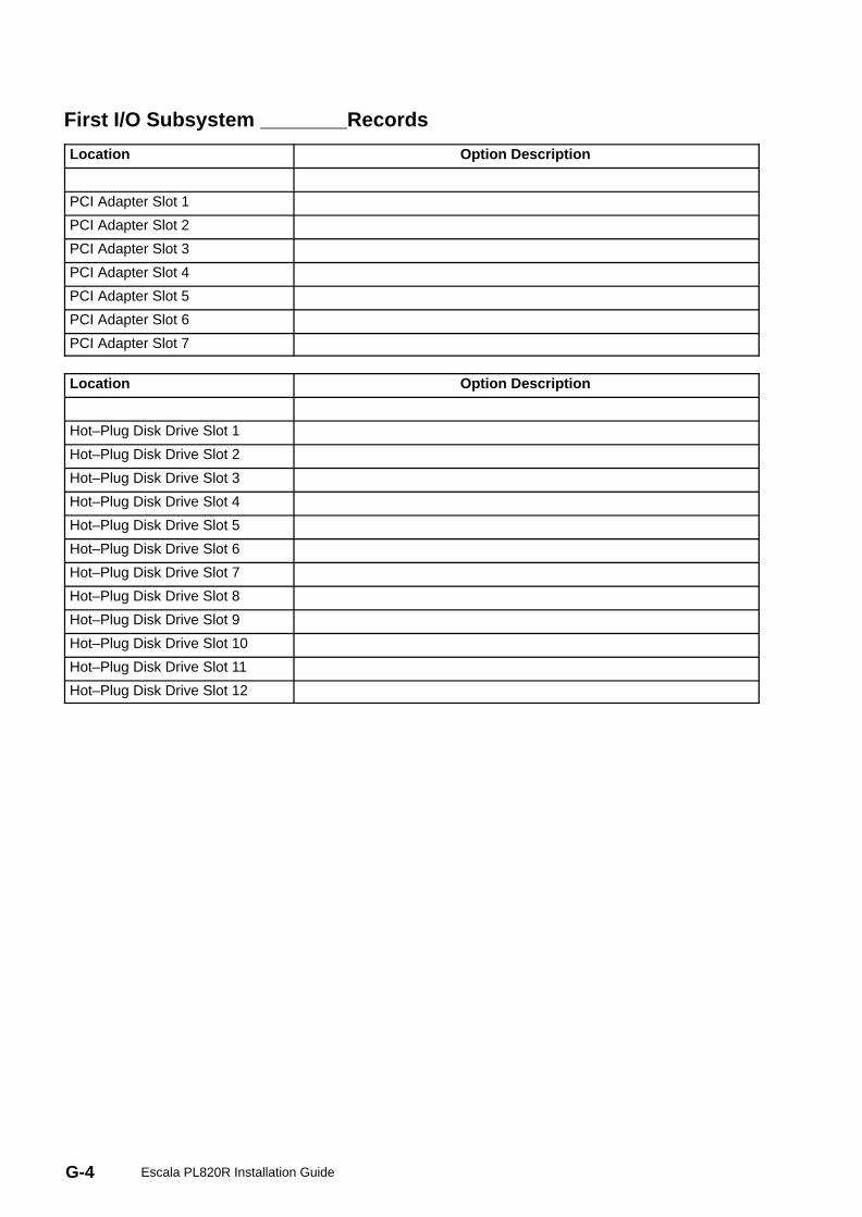
G-4 Escala PL820R Installation Guide
First I/O Subsystem Records
Location Option Description
PCI Adapter Slot 1
PCI Adapter Slot 2
PCI Adapter Slot 3
PCI Adapter Slot 4
PCI Adapter Slot 5
PCI Adapter Slot 6
PCI Adapter Slot 7
Location Option Description
Hot–Plug Disk Drive Slot 1
Hot–Plug Disk Drive Slot 2
Hot–Plug Disk Drive Slot 3
Hot–Plug Disk Drive Slot 4
Hot–Plug Disk Drive Slot 5
Hot–Plug Disk Drive Slot 6
Hot–Plug Disk Drive Slot 7
Hot–Plug Disk Drive Slot 8
Hot–Plug Disk Drive Slot 9
Hot–Plug Disk Drive Slot 10
Hot–Plug Disk Drive Slot 11
Hot–Plug Disk Drive Slot 12

G-5System Records
Second I/O Subsystem Records
Location Option Description
PCI Adapter Slot 1
PCI Adapter Slot 2
PCI Adapter Slot 3
PCI Adapter Slot 4
PCI Adapter Slot 5
PCI Adapter Slot 6
PCI Adapter Slot 7
Location Option Description
Hot–Plug Disk Drive Slot 1
Hot–Plug Disk Drive Slot 2
Hot–Plug Disk Drive Slot 3
Hot–Plug Disk Drive Slot 4
Hot–Plug Disk Drive Slot 5
Hot–Plug Disk Drive Slot 6
Hot–Plug Disk Drive Slot 7
Hot–Plug Disk Drive Slot 8
Hot–Plug Disk Drive Slot 9
Hot–Plug Disk Drive Slot 10
Hot–Plug Disk Drive Slot 11
Hot–Plug Disk Drive Slot 12
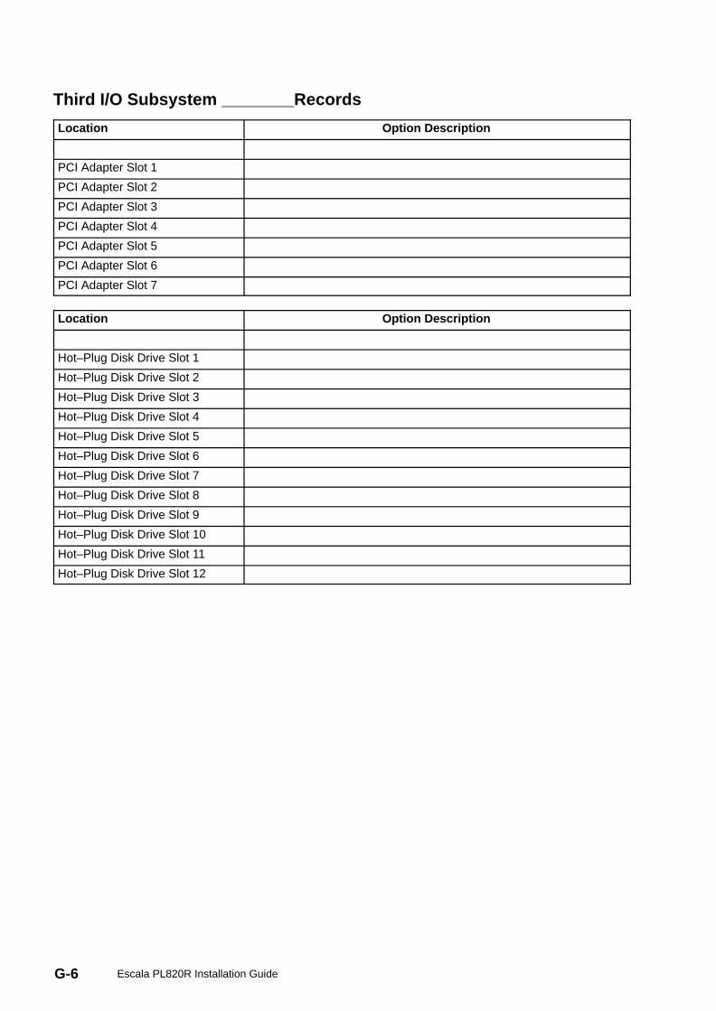
G-6 Escala PL820R Installation Guide
Third I/O Subsystem Records
Location Option Description
PCI Adapter Slot 1
PCI Adapter Slot 2
PCI Adapter Slot 3
PCI Adapter Slot 4
PCI Adapter Slot 5
PCI Adapter Slot 6
PCI Adapter Slot 7
Location Option Description
Hot–Plug Disk Drive Slot 1
Hot–Plug Disk Drive Slot 2
Hot–Plug Disk Drive Slot 3
Hot–Plug Disk Drive Slot 4
Hot–Plug Disk Drive Slot 5
Hot–Plug Disk Drive Slot 6
Hot–Plug Disk Drive Slot 7
Hot–Plug Disk Drive Slot 8
Hot–Plug Disk Drive Slot 9
Hot–Plug Disk Drive Slot 10
Hot–Plug Disk Drive Slot 11
Hot–Plug Disk Drive Slot 12
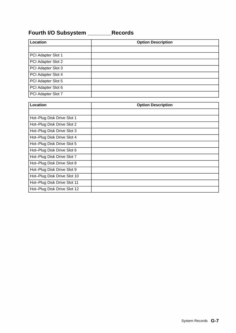
G-7System Records
Fourth I/O Subsystem Records
Location Option Description
PCI Adapter Slot 1
PCI Adapter Slot 2
PCI Adapter Slot 3
PCI Adapter Slot 4
PCI Adapter Slot 5
PCI Adapter Slot 6
PCI Adapter Slot 7
Location Option Description
Hot–Plug Disk Drive Slot 1
Hot–Plug Disk Drive Slot 2
Hot–Plug Disk Drive Slot 3
Hot–Plug Disk Drive Slot 4
Hot–Plug Disk Drive Slot 5
Hot–Plug Disk Drive Slot 6
Hot–Plug Disk Drive Slot 7
Hot–Plug Disk Drive Slot 8
Hot–Plug Disk Drive Slot 9
Hot–Plug Disk Drive Slot 10
Hot–Plug Disk Drive Slot 11
Hot–Plug Disk Drive Slot 12

G-8 Escala PL820R Installation Guide
Fifth I/O Subsystem Records
Location Option Description
PCI Adapter Slot 1
PCI Adapter Slot 2
PCI Adapter Slot 3
PCI Adapter Slot 4
PCI Adapter Slot 5
PCI Adapter Slot 6
PCI Adapter Slot 7
Location Option Description
Hot–Plug Disk Drive Slot 1
Hot–Plug Disk Drive Slot 2
Hot–Plug Disk Drive Slot 3
Hot–Plug Disk Drive Slot 4
Hot–Plug Disk Drive Slot 5
Hot–Plug Disk Drive Slot 6
Hot–Plug Disk Drive Slot 7
Hot–Plug Disk Drive Slot 8
Hot–Plug Disk Drive Slot 9
Hot–Plug Disk Drive Slot 10
Hot–Plug Disk Drive Slot 11
Hot–Plug Disk Drive Slot 12
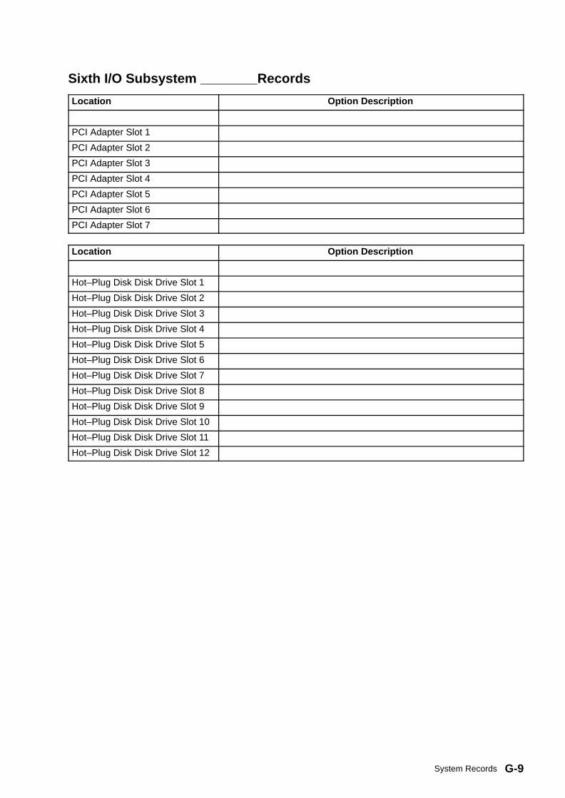
G-9System Records
Sixth I/O Subsystem Records
Location Option Description
PCI Adapter Slot 1
PCI Adapter Slot 2
PCI Adapter Slot 3
PCI Adapter Slot 4
PCI Adapter Slot 5
PCI Adapter Slot 6
PCI Adapter Slot 7
Location Option Description
Hot–Plug Disk Disk Drive Slot 1
Hot–Plug Disk Disk Drive Slot 2
Hot–Plug Disk Disk Drive Slot 3
Hot–Plug Disk Disk Drive Slot 4
Hot–Plug Disk Disk Drive Slot 5
Hot–Plug Disk Disk Drive Slot 6
Hot–Plug Disk Disk Drive Slot 7
Hot–Plug Disk Disk Drive Slot 8
Hot–Plug Disk Disk Drive Slot 9
Hot–Plug Disk Disk Drive Slot 10
Hot–Plug Disk Disk Drive Slot 11
Hot–Plug Disk Disk Drive Slot 12
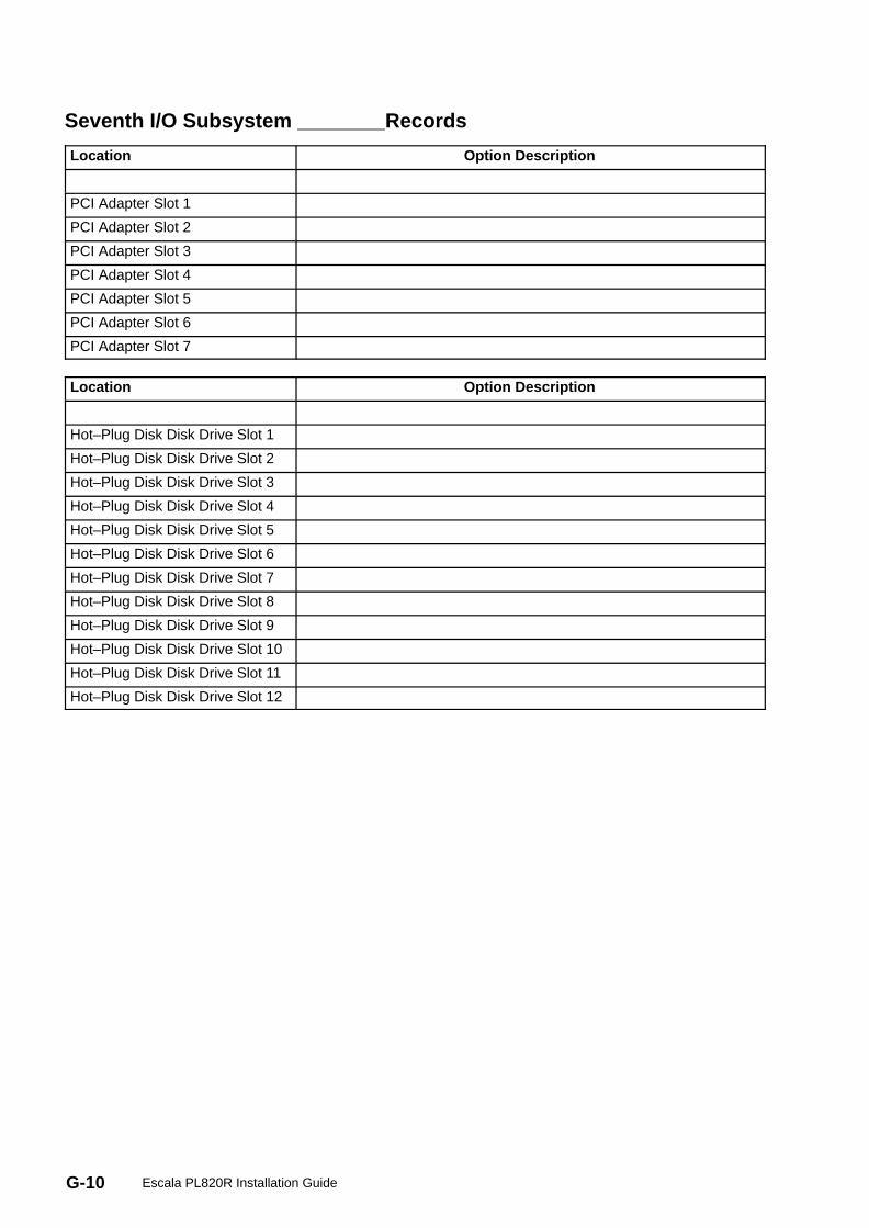
G-10 Escala PL820R Installation Guide
Seventh I/O Subsystem Records
Location Option Description
PCI Adapter Slot 1
PCI Adapter Slot 2
PCI Adapter Slot 3
PCI Adapter Slot 4
PCI Adapter Slot 5
PCI Adapter Slot 6
PCI Adapter Slot 7
Location Option Description
Hot–Plug Disk Disk Drive Slot 1
Hot–Plug Disk Disk Drive Slot 2
Hot–Plug Disk Disk Drive Slot 3
Hot–Plug Disk Disk Drive Slot 4
Hot–Plug Disk Disk Drive Slot 5
Hot–Plug Disk Disk Drive Slot 6
Hot–Plug Disk Disk Drive Slot 7
Hot–Plug Disk Disk Drive Slot 8
Hot–Plug Disk Disk Drive Slot 9
Hot–Plug Disk Disk Drive Slot 10
Hot–Plug Disk Disk Drive Slot 11
Hot–Plug Disk Disk Drive Slot 12

G-11System Records
Eighth I/O Subsystem Records
Location Option Description
PCI Adapter Slot 1
PCI Adapter Slot 2
PCI Adapter Slot 3
PCI Adapter Slot 4
PCI Adapter Slot 5
PCI Adapter Slot 6
PCI Adapter Slot 7
Location Option Description
Hot–Plug Disk Drive Slot 1
Hot–Plug Disk Drive Slot 2
Hot–Plug Disk Drive Slot 3
Hot–Plug Disk Drive Slot 4
Hot–Plug Disk Drive Slot 5
Hot–Plug Disk Drive Slot 6
Hot–Plug Disk Drive Slot 7
Hot–Plug Disk Drive Slot 8
Hot–Plug Disk Drive Slot 9
Hot–Plug Disk Drive Slot 10
Hot–Plug Disk Drive Slot 11
Hot–Plug Disk Drive Slot 12

G-12 Escala PL820R Installation Guide

X-1Index
IndexAacoustical, noise, emissions, B-2adapter cables, connecting, 1-16adapters placement, C-2AIX operating system documentation, 1-21, 4-8
disposal, recycling, B-1testing, E-2
Ccolor coded indicators, 4-2configuration
client, 2-7NIM server, 2-6service processor, serial port, E-2
connect external SCSI devices, 1-16connect internal Ethernet, 1-18connecting
adapter cables, 1-16graphics display, 1-12keyboard and mouse, 1-13power cables, 1-18serial and parallel devices, 1-14
console, display type, 1-11
Ddevice records, G-2diagnostics
loading, 2-5online, loading, 2-4standalone
loading, 2-4NIM server, 2-6
stopping, 2-8disk drive slot LED, 4-3
Eexternal SCSI devices, connecting, 1-16
Ffirmware, F-1
level, F-1update, F-1
firmware updates, system, F-1
Ggraphics display
connecting, 1-12, 4-2operation, verifying, 2-1verification, considerations, 2-1
HHMC cabling, D-8HMC, connecting, 1-11
Iinstall, 1-8installation, 3-1installation, system, 1-1
installing options, 4-1internal Ethernet, connection, 1-18
Kkeyboard and mouse, connection, v, 1-13
LLED, disk drive, 4-3loading
online diagnostics, 2-4standalone diagnostic, 2-4
NNIM server
configuration, 2-6client, 2-7
standalone diagnostics, 2-6noise emissions, acoustical, B-2notices, iii
Oonline diagnostics, loading, 2-4operating system documentation, AIX, 1-21, 4-8operation, loading, verifying, 2-1options installation, 4-1
devices, handling static–sensitive, 4-1, 4-2stopping the system, 4-3
PPCI, adapter removal, 4-9PCI adapters placement, C-2power cables, connecting, 1-18product disposal, B-1publications, related, door installation, 1-5, 3-1
Rrecords
device, 2-10system, 2-10updating, 2-10
records, device, G-2records, system, G-1recycling, B-1related publications, iii, v, 4-1
Sserial and parallel devices, connection, 1-14service processor
checklist, E-1serial port, configuration, E-2setup, E-1setup checklist, E-1test, E-1
setup and test, service processor, E-1standalone diagnostics
loading, 2-4NIM server, 2-6, 2-7
stopping, diagnostics, 2-8stopping the system, 4-3

X-2 ESCALA PL 820R Installation Guide
systemoverview, 1-1records, updating, 2-10stopping, 4-3verification
additional, 2-8running, 2-8
system firmware updates, F-1system installation, 1-1system records, G-1
key serial number, G-1serial number, G-1
Ttesting the setup, E-2
Uupdating, system, records, 2-10
Vverification, system, additional, 2-8verification, system, 2-8verifying, hardware operation, 2-1
Wweb sites
firmware yupdates, F-1microcode updates, F-1

Vos remarques sur ce document / Technical publication remark form
Titre / Title : Bull ESCALA PL 820R Installation Guide
Nº Reférence / Reference Nº : 86 A1 19EG 01 Daté / Dated : May 2003
ERREURS DETECTEES / ERRORS IN PUBLICATION
AMELIORATIONS SUGGEREES / SUGGESTIONS FOR IMPROVEMENT TO PUBLICATION
Vos remarques et suggestions seront examinées attentivement.Si vous désirez une réponse écrite, veuillez indiquer ci-après votre adresse postale complète.
Your comments will be promptly investigated by qualified technical personnel and action will be taken as required.If you require a written reply, please furnish your complete mailing address below.
NOM / NAME : Date :
SOCIETE / COMPANY :
ADRESSE / ADDRESS :
Remettez cet imprimé à un responsable BULL ou envoyez-le directement à :
Please give this technical publication remark form to your BULL representative or mail to:
BULL CEDOC357 AVENUE PATTONB.P.2084549008 ANGERS CEDEX 01FRANCE
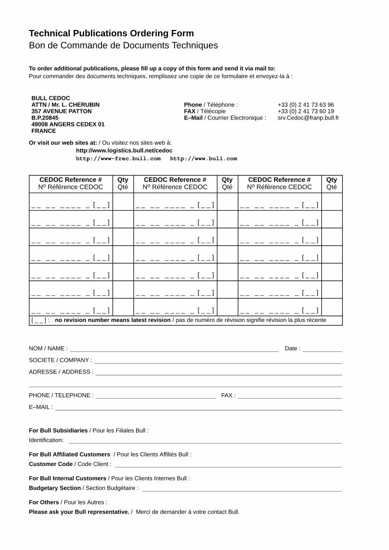
Technical Publications Ordering FormBon de Commande de Documents Techniques
To order additional publications, please fill up a copy of this form and send it via mail to:Pour commander des documents techniques, remplissez une copie de ce formulaire et envoyez-la à :
BULL CEDOCATTN / Mr. L. CHERUBIN357 AVENUE PATTONB.P.2084549008 ANGERS CEDEX 01FRANCE
Phone / Téléphone : +33 (0) 2 41 73 63 96FAX / Télécopie +33 (0) 2 41 73 60 19E–Mail / Courrier Electronique : [email protected]
Or visit our web sites at: / Ou visitez nos sites web à:http://www.logistics.bull.net/cedochttp://www–frec.bull.com http://www.bull.com
CEDOC Reference #No Référence CEDOC
QtyQté
CEDOC Reference #No Référence CEDOC
QtyQté
CEDOC Reference #No Référence CEDOC
QtyQté
_ _ _ _ _ _ _ _ _ [ _ _ ] _ _ _ _ _ _ _ _ _ [ _ _ ] _ _ _ _ _ _ _ _ _ [ _ _ ]
_ _ _ _ _ _ _ _ _ [ _ _ ] _ _ _ _ _ _ _ _ _ [ _ _ ] _ _ _ _ _ _ _ _ _ [ _ _ ]
_ _ _ _ _ _ _ _ _ [ _ _ ] _ _ _ _ _ _ _ _ _ [ _ _ ] _ _ _ _ _ _ _ _ _ [ _ _ ]
_ _ _ _ _ _ _ _ _ [ _ _ ] _ _ _ _ _ _ _ _ _ [ _ _ ] _ _ _ _ _ _ _ _ _ [ _ _ ]
_ _ _ _ _ _ _ _ _ [ _ _ ] _ _ _ _ _ _ _ _ _ [ _ _ ] _ _ _ _ _ _ _ _ _ [ _ _ ]
_ _ _ _ _ _ _ _ _ [ _ _ ] _ _ _ _ _ _ _ _ _ [ _ _ ] _ _ _ _ _ _ _ _ _ [ _ _ ]
_ _ _ _ _ _ _ _ _ [ _ _ ] _ _ _ _ _ _ _ _ _ [ _ _ ] _ _ _ _ _ _ _ _ _ [ _ _ ]
[ _ _ ] : no revision number means latest revision / pas de numéro de révision signifie révision la plus récente
NOM / NAME : Date :
SOCIETE / COMPANY :
ADRESSE / ADDRESS :
PHONE / TELEPHONE : FAX :
E–MAIL :
For Bull Subsidiaries / Pour les Filiales Bull :
Identification:
For Bull Affiliated Customers / Pour les Clients Affiliés Bull :
Customer Code / Code Client :
For Bull Internal Customers / Pour les Clients Internes Bull :
Budgetary Section / Section Budgétaire :
For Others / Pour les Autres :
Please ask your Bull representative. / Merci de demander à votre contact Bull.


BULL CEDOC357 AVENUE PATTONB.P.2084549008 ANGERS CEDEX 01FRANCE
86 A1 19EG 01ORDER REFERENCE
PLA
CE
BA
R C
OD
E IN
LO
WE
RLE
FT
CO
RN
ER
Utiliser les marques de découpe pour obtenir les étiquettes.Use the cut marks to get the labels.
86 A1 19EG 01
Installation Guide
ESCALA PL820R
86 A1 19EG 01
Installation Guide
ESCALA PL820R
86 A1 19EG 01
Installation Guide
ESCALA PL820R