Building,types of building and case study about redential building
Upload
ehecatl-xxiCategory
view
187download
0
PROJECTS: TENSEGRITY TOWER www.makezine.com/06/tensegrity
101Make:100 Make: Volume 06
BUILDING TENSEGRITY MODELS By William Gurstelle
Make a “needle tower” sculpture from dowels and elastic cord that seems to defy the laws of physics. >>
Ph
otog
rap
hy b
y K
irk
von
Roh
r
Set up: p.106 Make it: p.107 Use it: p.113
One of the most striking sculptures on display at the Smithsonian’s Hirshhorn Museum in Washington, D.C., is the soaring, 60-foot-tall Needle Tower. It’s made of a latticework of aluminum tubes held together by crossed stainless steel wires under tension. Sculptor Kenneth Snelson’s creation is a fragile-looking construction. Common sense tells you it ought to fall over or implode. Yet it’s been standing strong and upright since 1968, unperturbed by storms and wind or even the occasional renegade urban climber. The rods that make up the bulk of the tower float in midair, held together only by wires that are not guyed or anchored to the ground; they are not attached to anything but the compression rods themselves. It forces you to think: just what is pushing on what? How does it stand?
HOW HIGH CAN YOU GO?
William Gurstelle is a frequent MAKE contributor. His new book, Adventures from the Technology Underground, was published in January.

PROJECTS: TENSEGRITY TOWER
103Make:102 Make: Volume 06
MEET THE TENDULE
Illus
trat
ions
by
Tim
Lill
is/n
arw
halc
reat
ive.
com
It’s a only a small step from the kite frame to the simplest true tensegrity structure, a basic, versatile, and elegant structure which I call a tendule (Figure 2).
Tendules have three compression mem-bers that form a stable and (unlike the kite shape) three-dimensional building block. This is the basic building unit of Snelson’s Needle Tower and a host of other tensegrity structures.
The three essential components of a tensegrity tendule are as follows:
1. The compression members (wooden dowels)
2. The tension members (stretchy cords), which consist of: A. The cord triangle loops: The two tension members in every tendule that connect the three compression mem-bers in the horizontal plane. B. The vertical cords: The three tension members in every tendule that connect the top of each compression member to a corresponding bottom in an adjacent compression member.
3. The tension-compression interface (eye screws)
A SHORT HISTORY OF FLOATING COMPRESSION STRUCTURESThe key to understanding the Needle Tower and a number of other Snelson works is a principle popularly referred to as tensegrity, a combination of tension and integrity. This is a neologism coined by Buckminster Fuller, a man who loved to create new words by truncating and fusing others: dymaxion (dynamic maximum tension), synergetics (syner-getic geometry), and sunsight (sun and first sight). Origins of TensegritySome writers claim the notion of tensegrity was first put forward by Snelson in 1948, when he described a technique he used in building artistic constructions as “floating compression.” Snelson shared his ideas with Fuller, who quickly saw both novelty and practicality in the idea. An expert at providing interesting names to concepts, he reworked and then renamed this generalized idea of structures held together by compression members, which are held in place by flexible wires in tension. When Fuller coined and began popularizing the term tensegrity in 1961, apparently he did so with-out Snelson’s consent. In fact, there is something of a controversy among scientists, artists, and architects as to who rightfully deserves more of the credit for devising the concept. Snelson claims quite vociferously that the famous and powerful Fuller more or less usurped his idea and denied him recognition, while Fullerites scoff at the idea that anybody but Bucky deserves credit. Yet others maintain that the idea predates both of them, and belongs either to an obscure Latvian art-ist named Karl Loganson, who some say developed the idea in the early 1920s, or to French architect David Georges Emmerich, who began exploring and refining the basic building structures of tensegrity in the 1950s. Tensegrity’s true provenance is difficult to ascer-tain given the number of competing claims and the documentation on the subject. Many, if not all, of these erstwhile creators likely had a hand in devel-oping and extending the concept. Almost certainly, each advanced the idea in important ways. Em-merich, Fuller, and Snelson each filed patent claims on differing aspects of the technology in the 1960s.
In its most basic form, a tensegrity structure is simply a construction made from two crossed rods, held in place with a tightened cord around its perimeter (Figure 1). It’s easy to see that if the cord is in tension, then the rods are under compression. But this kite shape is actually a quasi-tensegrity, because the crossed rods touch each other in the middle. In a true tensegrity, no compression members make contact.
tension
compression
Tensegrity describes structures composed of three or more rods held in place by a net-work of tension wires. No rod may touch another rod.
Pho
togr
aphy
det
ail c
ourt
esy
of th
e H
irsh
horn
Mus
eum
and
Scu
lptu
re G
arde
n, S
mith
soni
an In
stitu
tion,
Gift
of J
osep
h H
. Hir
shho
rn, 1
974.
Im
age
by R
icar
do B
lanc
2A.
2B.
3.
1.
Fig. 2
Fig. 1
www.makezine.com/06/tensegrity

PROJECTS: TENSEGRITY TOWER www.makezine.com/06/tensegrity
105Make:104 Make: Volume 06
Now, it appears that each man had a much different opinion on the highest and best use of this idea. Fuller’s primary interest in the concept was its application toward engineering — specifically, the spherical and dome-like enclosures (i.e., geodesic structures) for which he became famous. Emmer-ich, the architect, saw tensegrity’s value residing primarily in its utility as a building construction technique. And Kenneth Snelson, the artist, primarily sees tensegrity’s value in an aesthetic sculptural context. Irrespective of who actually first developed the concepts and the principles behind the building technique, tensegrity structures are fun to make and interesting to look at.
Toward a Floating TowerEver want to make something that is cool simply for its own sake? The English might term such a project as “folly” — an eccentric sort of activity without much practical value, but valuable because of its
interesting and out-of-the-ordinary nature. It’s the sort of unusual, impractical, but enthralling project that makers seek out. If you’re a regular reader of this magazine, you know what I’m talking about. This is one of those projects. Be aware, the project that follows can lead to a pleasant sort of addiction. Once you master the techniques shown here, you may find yourself build-ing a great number of tensegrity structures. Also, be forewarned that the first time you build one, it will be frustrating. Cords will break, the modules that make up the structure may be uneven and tilted, the towers will lean or list, or worse, come crashing down in a heap. Eventually, the technique will make sense. The materials are somewhat forgiving, and misalignments can often be corrected by gentle massage and your force of concentration.
A Few Background NotesI first came across the idea of tensegrity in a 1996 edition of The Physics Teacher magazine. The au-thor of that article, a University of Michigan faculty member, described his encounter with Snelson’s Needle Tower at the Hirshhorn Museum as an experience that left him puzzled and intrigued. The author provided directions and sketches to enable the magazine’s readers to replicate on a smaller scale the fragile-looking, semi-rigid column that seems to float on air. When I tried to make my own column, I was less than successful. I followed the instructions closely, but it was apparent that the technique described in the article required either the manual dexterity of a Flying Karamazov chainsaw juggler or a prehensile tail to act as a third hand. Lacking both, the struc-ture I tried to build invariably collapsed, sometimes slowly, sometimes quite spectacularly, and often just on the brink of success. But, perseverance is the mother of good luck, and I eventually came up with an easy-to-replicate modeling technique that works quite well, even for people limited to just ten fingers.
Building Tensegrity StructuresIn Fuller’s 1962 U.S. patent application, tensegrity is described as “a plurality of discontinuous com-pression columns arranged in groups of three nonconjunctive columns connected by tension elements forming tension triangles.” Huh? No wonder tensegrity sculptures seem hard to make.
Happily, a lot of other people, from artists to scientists, have developed their own definitions:
Tensegrity is a structure composed of three or more rods held in place by a network of tension wires. No rod may touch another rod. Rods may be supported in place solely by the tension wires to form a firm, prestressed, and semi-rigid structural unit.
This description is somewhat more user friendly. It provides a set of conditions that can be used to determine whether a structure uses tensegrity construction techniques or not. But after you work with it a while, tensegrity becomes easy to identify, even if it remains difficult to describe in words. To paraphrase Supreme Court Justice Potter Stewart’s 1964 quote, “I shall not attempt further to define this kind of material, but I know it when I see it.”
Floating Compression ModelingTensegrity models can be made from inexpensive materials such as hardwood dowels and elastic cord, or even just rubber bands and pencils. More elaborate models occasionally are made using brass rods or steel shafts. All tensegrity structures described in this article are built up from basic building blocks called
tension modules (which, to be Fullerian about it, I call tendules). A tendule is composed of three rods that support compressive loads and five triangulat-ed wires or bands that handle tension loads. When arranged in a specific style of latticework, the rods and wires form stable building blocks that can be turned into towers, bridges, and other, even more elaborate space-enclosing structures. To take on larger shapes, the tendules rely on a building principle called floating compression. None of the rods touch one another, and loads are transmitted from rod to rod through a matrix of tensioned wires. Because the wires are very thin and the rods are relatively thick and widely separated in space, the overall visual effect is that of unsupport-ed struts or poles floating in air — a most unusual and novel spatial aesthetic.
Building a Tensegrity TowerThe instructions in the following section detail the materials and techniques used in building a model of Snelson’s Needle Tower. The model is four tiers or stories high, although fewer or more tiers can be incorporated according to the wishes of the builder. The original Needle Tower at the Hirshhorn Museum has more than 15 tiers.
Buckminster Fuller built this geodesic dome in 1962. He developed some of his ideas about tensegrity after meeting a young Kenneth Snelson in the late 1940s. A fascinating letter written by Snelson and printed in the International Journal of Space Structures in 1990 is reprinted here: grunch.net/snelson/rmoto.html.
Illus
trat
ion
from
the
U.S
. Pat
ent &
Tra
dem
ark
Off
ice
web
site
Pho
togr
aph
cour
tesy
, The
Est
ate
of R
. Buc
kmin
ster
Ful
ler
107Make:
PROJECTS: TENSEGRITY TOWER www.makezine.com/06/tensegrity
106 Make: Volume 06
CONSTRUCT A TENSEGRITY TOWER
START>>
MAKE IT.
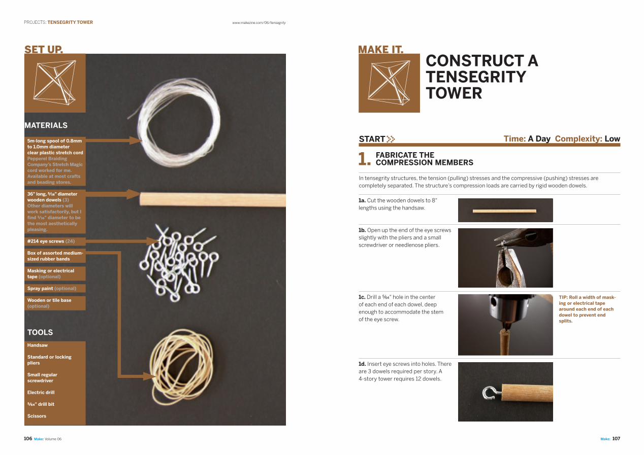
In tensegrity structures, the tension (pulling) stresses and the compressive (pushing) stresses are completely separated. The structure’s compression loads are carried by rigid wooden dowels.
1. FABRICATE THE COMPRESSION MEMBERS
Time: A Day Complexity: Low
1a. Cut the wooden dowels to 8" lengths using the handsaw.
SET UP.
TOOLS
Handsaw
Standard or locking pliers
Small regular screwdriver
Electric drill
E" drill bit
Scissors
TIP: Roll a width of mask-ing or electrical tape around each end of each dowel to prevent end splits.
1b. Open up the end of the eye screws slightly with the pliers and a small screwdriver or needlenose pliers.
1c. Drill a E" hole in the center of each end of each dowel, deep enough to accommodate the stem of the eye screw.
1d. Insert eye screws into holes. There are 3 dowels required per story. A 4-story tower requires 12 dowels.
MATERIALS
5m-long spool of 0.8mm to 1.0mm diameter clear plastic stretch cord Pepperel Braiding Company’s Stretch Magic cord worked for me. Available at most crafts and beading stores.
36" long, 7" diameter wooden dowels (3) Other diameters will work satisfactorily, but I find 7" diameter to be the most aesthetically pleasing.
#214 eye screws (24)
Box of assorted medium-sized rubber bands
Masking or electrical tape (optional)
Spray paint (optional)
Wooden or tile base (optional)

109Make:108
PROJECTS: TENSEGRITY TOWER www.makezine.com/06/tensegrity
Make: Volume 06
3. CONSTRUCT THE WEAVE TRIANGLES
2a. Make 8 loops from stretchy cord pieces, each piece being 15" long. Making the knot will consume an inch or so of cord, so the total length of the cord in the loop will be slightly less than 15". Because the cord is stretchy, there is some wiggle room in making the loops.
4. FORM THE CORD TRIANGLES
Tension in the structure is provided by loops of stretchy plastic cord. The cord packaging should carry instructions on how to tie the cord into loops. If there are no instructions, try either a square knot or a double overhand knot, pulled as tight as possible.
2. FABRICATE THE CORDS
2b. Make 9 loops from cord pieces cut 8" long.
2c. Make 12 loops from cord pieces cut 10" long.
Tendules begin as a set of dowels arranged in groups of 3 to form preliminary weave triangles. There will be 2 left and 2 right weave triangles.
3a. Place a pencil mark at a point 3" from each end of each dowel. Align dowel pencil marks to form a left weave triangle. Tightly wrap a rubber band around the pencil marks to hold the triangle together. Repeat for the second left weave triangle.
3b. Now align the dowels to form a right weave triangle, pencil mark to pencil mark, and wrap it tightly with rubber bands. Repeat for the second right weave triangle. You now have 4 flattened weave triangles, 2 left-handed and 2 right-handed. (You can make more later, if you want to build a higher tower.)
NOTE: The rubber bands are only temporary. You’ll cut them off later.
The cord triangles are the triangles formed by the stretchy cords. In the photo below, weave triangles are the triangles formed by the wooden dowels, and the cord triangles are the triangles colored red and blue.
4a. Attach the 15" cord to the top set of opened eye screws on a weave tri-angle (as shown in blue). Then attach another 15" cord to the bottom set of eye screws on the triangle (as shown in red). Note how the top and bottom stretch cords form 2 cord triangles.
4b. The best way to form the cord triangles is to loop the cord once around the base of each eye screw. The cord should be stretched tightly but evenly in each cord triangle; that is, each third of the triangle should have roughly the same tension. You can easily check the tension by plucking each segment of the stretched cord triangle with your fingernail and listening to the resulting pitch. When the plucked pitches are all equal, the tension in each segment is equal as well.
4c. Adjust the tension by wrapping extra turns of the cord around the eye screw post until the tension in all 3 segments of each cord triangle is the same. Although the plastic cord is applying lateral tension to the weave triangle, the rubber bands should prevent it from moving. If the weave triangle shifts or is unstable, tighten the rubber bands to prevent movement.
5a. Attach one of the 10" long cord loops to each top weave triangle eye screw and to the eye screw on the bot-tom triangle closest to it. The vertical cord connecting the eye screws (top to bottom) will be very loose at this point. Initially, you may need to loop the vertical cord once or twice around the eye screw base to keep it from slipping off.
Right weave Left weave
5. ATTACH THE VERTICAL CORDS
NOTE: These loop sizes are lengths that worked well for me, but your experience may be slightly different. You may need to increase or decrease the cord length depending on the type and diameter of stretch cord used.

111Make:110
PROJECTS: TENSEGRITY TOWER www.makezine.com/06/tensegrity
Make: Volume 06
6a. Use scissors to carefully cut the rubber bands. When the last band is cut, the tension within the upper and lower triangle cords will lift up the structure to form a 3D shape, while the tension in the vertical connecting cords will constrain the structure from moving too far. The result is a box-like shape. Finding the correct balance between the lateral (cord triangle) tension members and the vertical ten-sion members aligns the compression members into semi-rigid, 3D tendules.
6d. Start by making single loops over the eye screws. Go easy at first on the number of loops, because making too many loops too quickly will cause over-tightening in one plane of the tendule and misalign-ment in the others.
6. FORM THE TENDULES
Tendules are the basic tensegrity building blocks. A single tendule is a compression-tension structure that is freestanding and stable. Larger structures are made by linking one tendule to another.
6e. Check the tension by plucking the cord after each eye screw loop adjustment until the tension is evenly distributed and the desired boxy shape is attained.
6f. Once you’ve figured out how to manipulate the tension in the triangle to form an evenly aligned tendule, make 3 more.
7a. Place one tendule on the base. Set a tendule of the opposite handedness on top of the base tendule. Rotate the upper tendule so that its eye screw touches the triangle cord on the base tendule halfway between eye screws. Loop the upper tendule’s eye screws around the triangle cord (colored red in the photo) several times. Adjust ten-sion in the tower cords by looping until the tension in all cords is equal.
7. ERECT THE TOWER
The tensegrity tower is erected by placing one tendule on top of another, alternating left-handed and right-handed tendules as you go. Each tendule is fixed to the ones above and below by triangulating. This means that tension members (additional stretchy cords) are affixed to form stability triangles that connect stories together.
7b. Repeat for the third and fourth tendule in the tower, alternating the handedness of the tendule each time.
7c. Once all the tendules are stacked, it is time to triangulate the tower to make it rigid. Do this by connect-ing the 9 remaining 8" loops to form stability triangles between each row. Complete the stability triangles by ex-tending the 8" loop from each bottom eye screw to the bottom eye screw directly below it.
6b. Fluff and adjust the tendule by looping the plastic cords over the eye screws until it forms a box-like shape. The top and bottom triangle tension members are in blue, and the vertical connecting cords are in white.
6c. If the tendule droops, loop the top and bottom triangle cords additional times around the eye screw post while simultaneously reducing the tension in the vertical connectors. I’ve found that the hardest part of making a tensegrity tower is learning how to properly adjust the tension (“tun-ing”) in the plastic cord loops. Each adjustment affects all other tension members — it’s a sort of mechanical sudoku puzzle for your hands — so considerable tuning is required.

113Make:112
PROJECTS: TENSEGRITY TOWER www.makezine.com/06/tensegrity
Make: Volume 06
HINTS AND TIPS: 1. Often, much fluffing and tension adjusting is required to get the tendules to stand squarely. Take as much time as necessary to get this right.
2. Once you learn the basic technique, you can experiment with unequal-length compression members and variable tensions to obtain interesting shapes. Interesting variations include: square and five-sided weaves, using tendules whose compression members are all longer or shorter than the members in the adjoining tendule, or using compression members of varying sizes in the same tendule.
TENSEGRIFY YOUR WORLD
USE IT.7d. The colored lines in this photo show how each stability triangle is formed between the ends of 2 compression members in the lower tendule and the end of the descending compression member in the tendule above.
7e. Adjust all cords so that the tension in each tendule is even and the cords that connect the stacked tendules are evenly distributed. Again, test by plucking and listening. Add or subtract loops around the eye screws to even up tension in the structure.
7f. After adjustments are complete, the tensegrity tower should be stable and level.
FOR FURTHER STUDYTensengrity is a fascinating topic and there is much material available for further research.
Books:An Introduction to Tensegrity by Anthony Pugh, University of California Press, 1976.
Engineering a New Architecture by Tony Robbin, Yale University Press, 1996.
Websites:Kenneth Snelson: kennethsnelson.net
Buckminster Fuller: bfi.org
A Practical Guide to Tensegrity Design (a PDF file): angelfire.com/ma4/bob_wb/tenseg.pdf
Other:Images and Community: tensegrity.com
How to Build Tensegrity Structures out of Soda Straws: georgehart.com/virtual-polyhedra/ straw-tensegrity.html
The Hirshhorn Museum: hirshhorn.si.edu
Tensegrity in a Cell: makezine.com/go/cell
“The word ‘tensegrity’ is an invention: a contrac-tion of ‘tensional integrity.’ Tensegrity describes a structural-relationship principle in which structural shape is guaranteed by the finitely closed, compre-hensively continuous, tensional behaviors of the system and not by the discontinuous and exclusively local compressional member behaviors. Tensegrity provides the ability to yield increasingly without ultimately breaking or coming asunder.”
—Buckminster Fuller (from Synergetics, p. 372)
“Tensegrity describes a closed structural system composed of a set of three or more elongate com-pression struts within a network of tension tendons, the combined parts mutually supportive in such a way that the struts do not touch one another, but press outwardly against nodal points in the tension network to form a firm, triangulated, prestressed, tension and compression unit.”
—Kenneth Snelson (kennethsnelson.net/faqs/faq.htm)
Fuller vs. Snelson on the Definition of Tensegrity