building structures 1 fettuccine report
21
1 | Page Contents 1.0 Introduction 1.1 Precedent Study 2.0 Material Analysis 2.1 Fettuccine Strength 2.2 Glue Strength 3.0 Truss Analysis 3.1 Design Rationale 3.2 Bridge Design 4.0 Bridge Testing and Analysis 4.1 Bridge 1 4.2 Bridge 2 5.0 Conclusion 6.0 Individual Calculation Exercise
-
Upload
yassyed31 -
Category
Data & Analytics
-
view
84 -
download
0
Transcript of building structures 1 fettuccine report
1 | P a g e
Contents
1.0 Introduction
1.1 Precedent Study
2.0 Material Analysis
2.1 Fettuccine Strength
2.2 Glue Strength
3.0 Truss Analysis
3.1 Design Rationale
3.2 Bridge Design
4.0 Bridge Testing and Analysis
4.1 Bridge 1
4.2 Bridge 2
5.0 Conclusion
6.0 Individual Calculation Exercise
2 | P a g e
1.0 Introduction
The aim of this project is to successfully design an effective truss bridge through the
analysis conducted on precedent studies, as well as the points discussed throughout
the lectures. The material used to represent the trusses are fettuccine
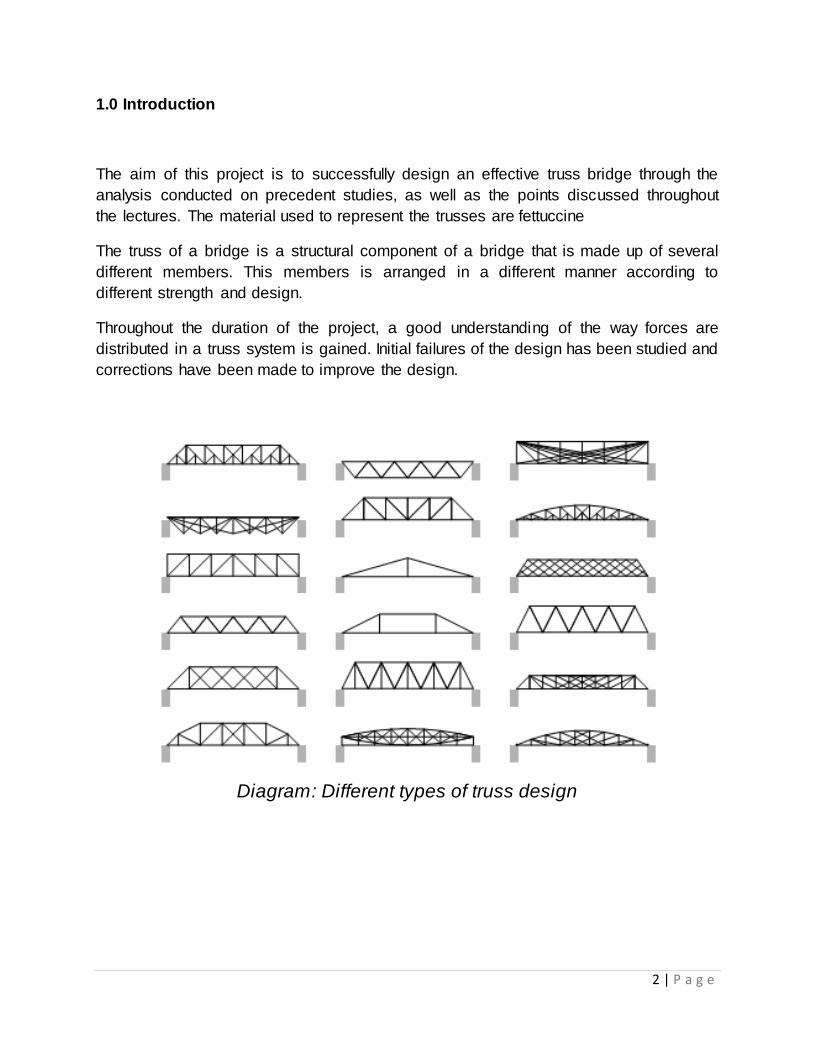
The truss of a bridge is a structural component of a bridge that is made up of several
different members. This members is arranged in a different manner according to
different strength and design.
Throughout the duration of the project, a good understanding of the way forces are
distributed in a truss system is gained. Initial failures of the design has been studied and
corrections have been made to improve the design.
Diagram: Different types of truss design
3 | P a g e
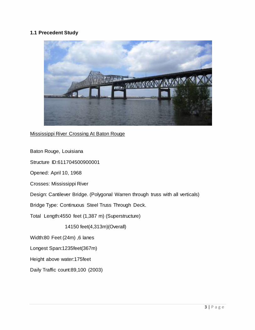
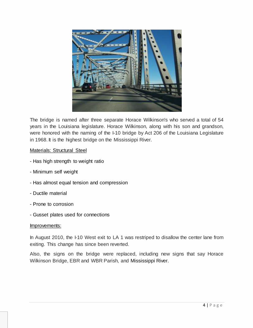
1.1 Precedent Study
Mississippi River Crossing At Baton Rouge
Baton Rouge, Louisiana
Structure ID:611704500900001
Opened: April 10, 1968
Crosses: Mississippi River
Design: Cantilever Bridge. (Polygonal Warren through truss with all verticals)
Bridge Type: Continuous Steel Truss Through Deck.
Total Length:4550 feet (1,387 m) (Superstructure)
14150 feet(4,313m)(Overall)
Width:80 Feet (24m) ,6 lanes
Longest Span:1235feet(367m)
Height above water:175feet
Daily Traffic count:89,100 (2003)
4 | P a g e
The bridge is named after three separate Horace Wilkinson's who served a total of 54
years in the Louisiana legislature. Horace Wilkinson, along with his son and grandson,
were honored with the naming of the I-10 bridge by Act 206 of the Louisiana Legislature
in 1968. It is the highest bridge on the Mississippi River.
Materials: Structural Steel
- Has high strength to weight ratio
- Minimum self weight
- Has almost equal tension and compression
- Ductile material
- Prone to corrosion
- Gusset plates used for connections
Improvements:
In August 2010, the I-10 West exit to LA 1 was restriped to disallow the center lane from
exiting. This change has since been reverted.
Also, the signs on the bridge were replaced, including new signs that say Horace
Wilkinson Bridge, EBR and WBR Parish, and Mississippi River.
5 | P a g e
2.0 Material Analysis
2.1 Fettuccine
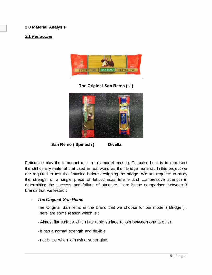
The Original San Remo ( √ )
San Remo ( Spinach ) Divella
Fettuccine play the important role in this model making. Fettucine here is to represent
the still or any material that used in real world as their bridge material. In this project we
are required to test the fettucine before designing the bridge. We are required to study
the strength of a single piece of fettuccine.as tensile and compressive strength in
determining the success and failure of structure. Here is the comparison between 3
brands that we tested :
- The Original San Remo
The Original San remo is the brand that we choose for our model ( Bridge ) .
There are some reason which is :
- Almost flat surface which has a big surface to join between one to other.
- It has a normal strength and flexible
- not brittle when join using super glue.
6 | P a g e
- San Remo ( Spinach )
From our assumption that the Spinach San Remo is not a good choice /
suitable for making fettuccine bridge. There is a reason that the spinach fettucine
is not suitable for fettuccine bridge, because it’s too soft which make the
fettuccine easy to break into pieces and also too flexible. When we pull it, it bend
too much and it’s make it more easier to break into pieces.
- Divella
From our research, Divella is not a good fettucine for bridge model.
Because the characteristic of divella not really meet the requirement of
making a fettuccine bridge. There are some reason that divella is not a
suitable brand to choose.it’s because the surface of divella is not flat
which is curvy so the surface for joining it together is very small and also
divella is thick which make the fettucine is not flexible enough and easy to
break.
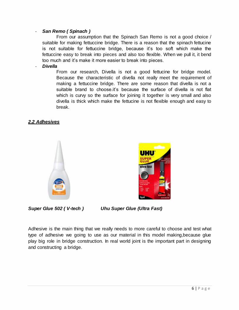
2.2 Adhesives
Super Glue 502 ( V-tech ) Uhu Super Glue (Ultra Fast)
Adhesive is the main thing that we really needs to more careful to choose and test what
type of adhesive we going to use as our material in this model making,because glue
play big role in bridge construction. In real world joint is the important part in designing
and constructing a bridge.
7 | P a g e
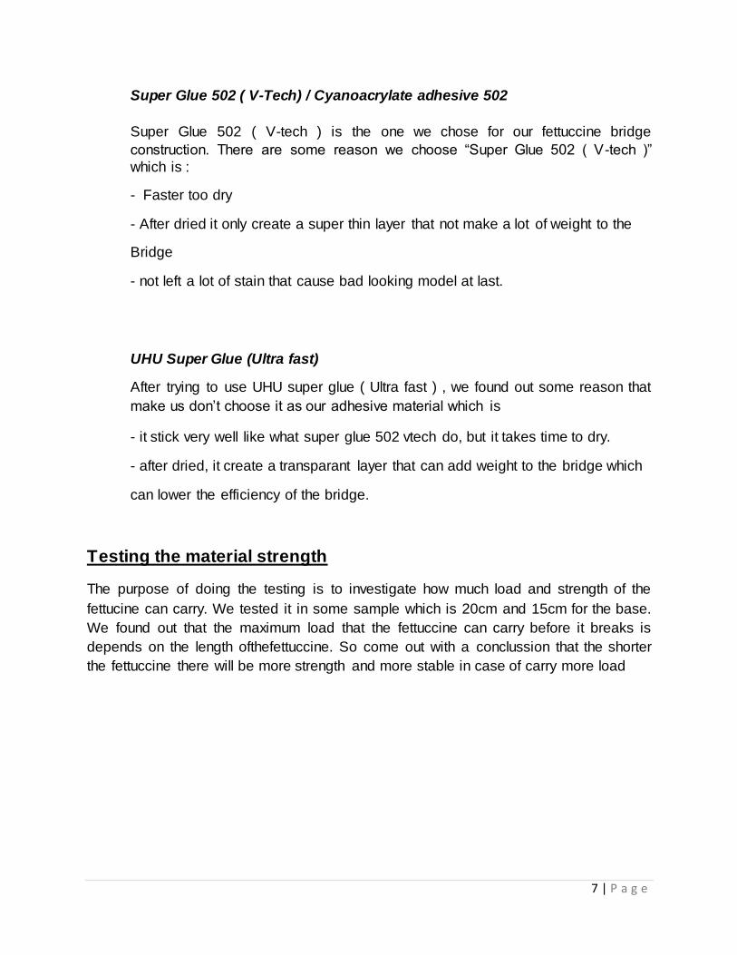
Super Glue 502 ( V-Tech) / Cyanoacrylate adhesive 502
Super Glue 502 ( V-tech ) is the one we chose for our fettuccine bridge
construction. There are some reason we choose “Super Glue 502 ( V-tech )”
which is :
- Faster too dry
- After dried it only create a super thin layer that not make a lot of weight to the
Bridge
- not left a lot of stain that cause bad looking model at last.
UHU Super Glue (Ultra fast)
After trying to use UHU super glue ( Ultra fast ) , we found out some reason that
make us don’t choose it as our adhesive material which is
- it stick very well like what super glue 502 vtech do, but it takes time to dry.
- after dried, it create a transparant layer that can add weight to the bridge which
can lower the efficiency of the bridge.
Testing the material strength
The purpose of doing the testing is to investigate how much load and strength of the
fettucine can carry. We tested it in some sample which is 20cm and 15cm for the base.
We found out that the maximum load that the fettuccine can carry before it breaks is
depends on the length ofthefettuccine. So come out with a conclussion that the shorter
the fettuccine there will be more strength and more stable in case of carry more load
8 | P a g e
3.0 DESIGN RATIONALE
To achieve projects requirements, we were to design a bridge constructed completely
out of fettuccini and glue, based on our knowledge of truss bridges, and information
gathered from the precedent studies. The limits of the project is that the final model
itself has to bear a minimum of 750 mm clear span as well as have a maximum weight
of 200g. It also has to be able to sustain a load hung from the centre of the clear span,
and have a degree of aesthetical value.
Various aspects had to be taken into consideration as the aim of the design is that of a
bridge of high efficiency, meaning it can bear a maximum load while using the least
amount of materials. However, there is not set weight limit it has to bear, as the bridge
will then be tested to fail, and its efficiency calculated from the results achieved.
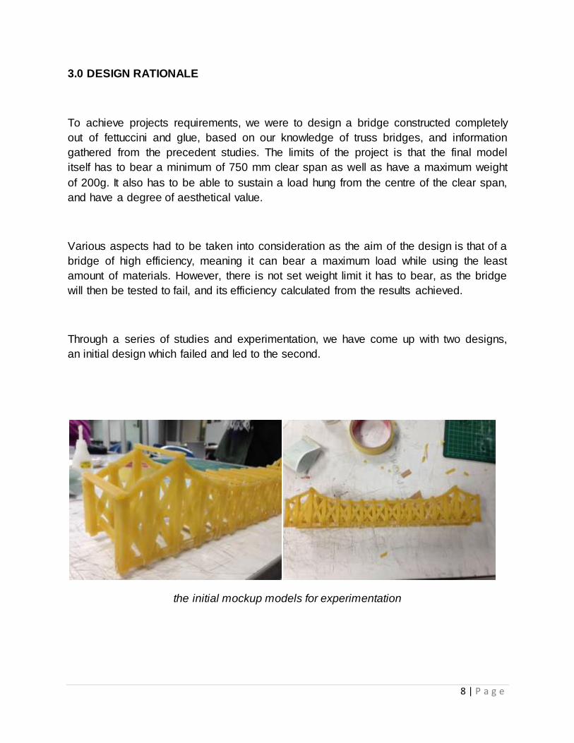
Through a series of studies and experimentation, we have come up with two designs,
an initial design which failed and led to the second.
the initial mockup models for experimentation
9 | P a g e
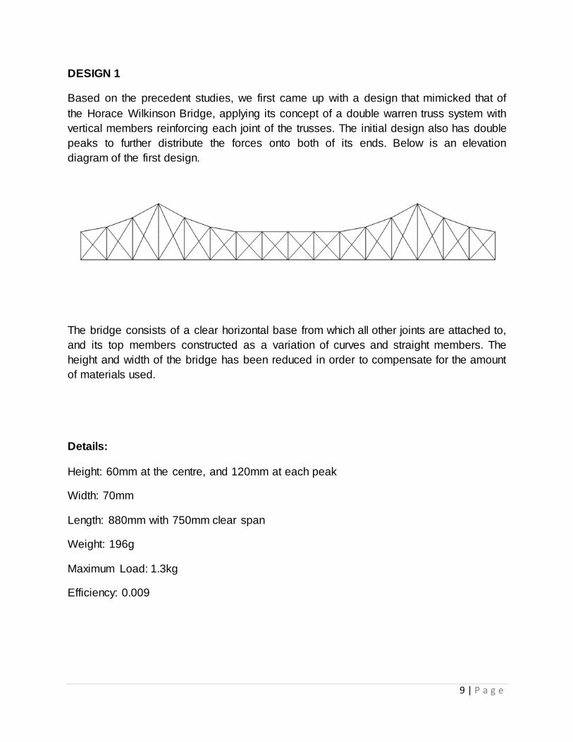
DESIGN 1
Based on the precedent studies, we first came up with a design that mimicked that of
the Horace Wilkinson Bridge, applying its concept of a double warren truss system with
vertical members reinforcing each joint of the trusses. The initial design also has double
peaks to further distribute the forces onto both of its ends. Below is an elevation
diagram of the first design.
The bridge consists of a clear horizontal base from which all other joints are attached to,
and its top members constructed as a variation of curves and straight members. The
height and width of the bridge has been reduced in order to compensate for the amount
of materials used.
Details:
Height: 60mm at the centre, and 120mm at each peak
Width: 70mm
Length: 880mm with 750mm clear span
Weight: 196g
Maximum Load: 1.3kg
Efficiency: 0.009
10 | P a g e
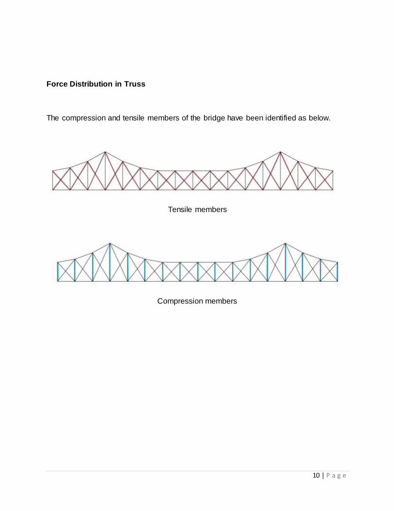
Force Distribution in Truss
The compression and tensile members of the bridge have been identified as below.
Tensile members
Compression members
11 | P a g e
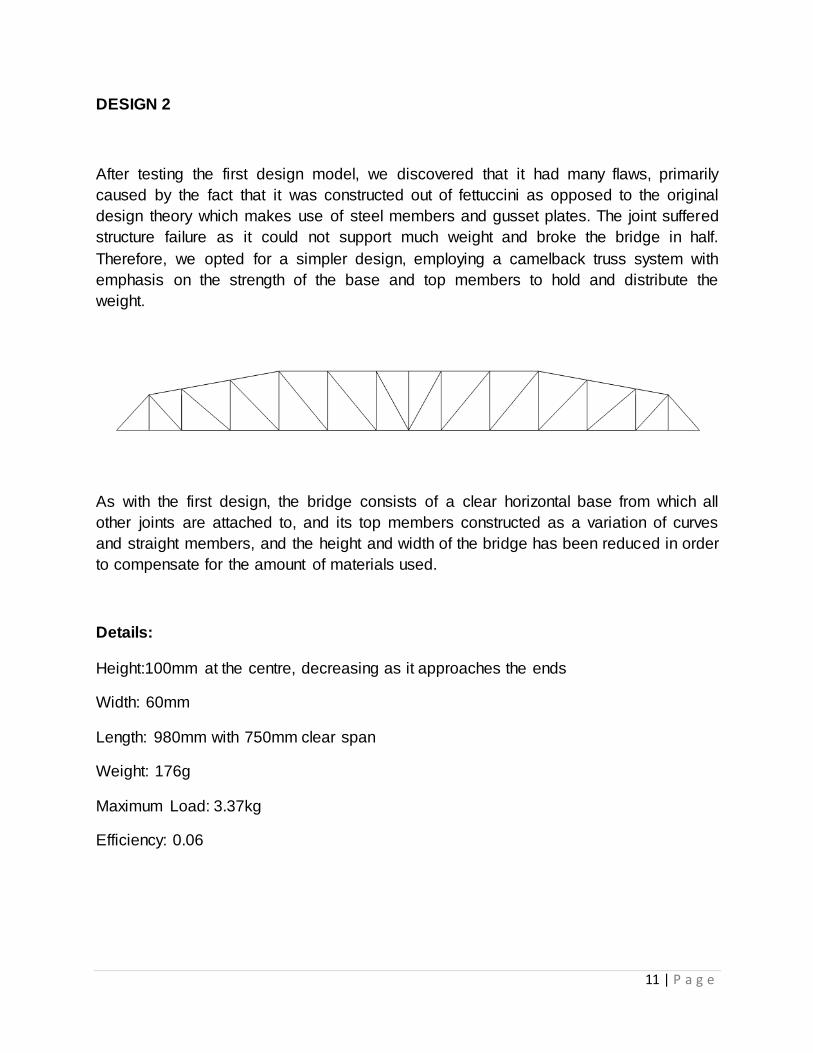
DESIGN 2
After testing the first design model, we discovered that it had many flaws, primarily
caused by the fact that it was constructed out of fettuccini as opposed to the original
design theory which makes use of steel members and gusset plates. The joint suffered
structure failure as it could not support much weight and broke the bridge in half.
Therefore, we opted for a simpler design, employing a camelback truss system with
emphasis on the strength of the base and top members to hold and distribute the
weight.
As with the first design, the bridge consists of a clear horizontal base from which all
other joints are attached to, and its top members constructed as a variation of curves
and straight members, and the height and width of the bridge has been reduced in order
to compensate for the amount of materials used.
Details:
Height:100mm at the centre, decreasing as it approaches the ends
Width: 60mm
Length: 980mm with 750mm clear span
Weight: 176g
Maximum Load: 3.37kg
Efficiency: 0.06
12 | P a g e
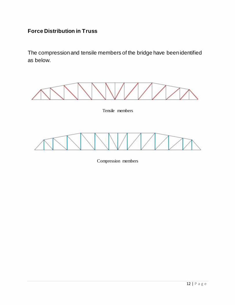
Force Distribution in Truss
The compression and tensile members of the bridge have been identified
as below.
Tensile members
Compression members
13 | P a g e
4.0 Bridge Testing and Analysis
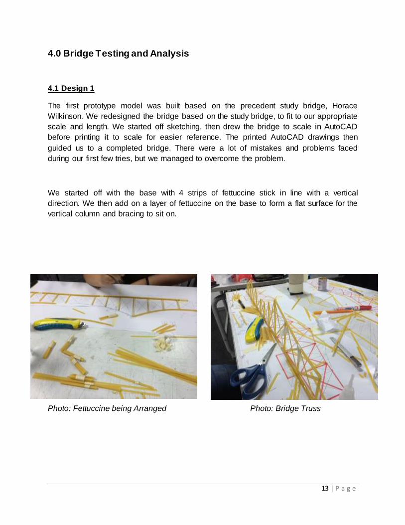
4.1 Design 1
The first prototype model was built based on the precedent study bridge, Horace
Wilkinson. We redesigned the bridge based on the study bridge, to fit to our appropriate
scale and length. We started off sketching, then drew the bridge to scale in AutoCAD
before printing it to scale for easier reference. The printed AutoCAD drawings then
guided us to a completed bridge. There were a lot of mistakes and problems faced
during our first few tries, but we managed to overcome the problem.
We started off with the base with 4 strips of fettuccine stick in line with a vertical
direction. We then add on a layer of fettuccine on the base to form a flat surface for the
vertical column and bracing to sit on.
Photo: Fettuccine being Arranged Photo: Bridge Truss
14 | P a g e
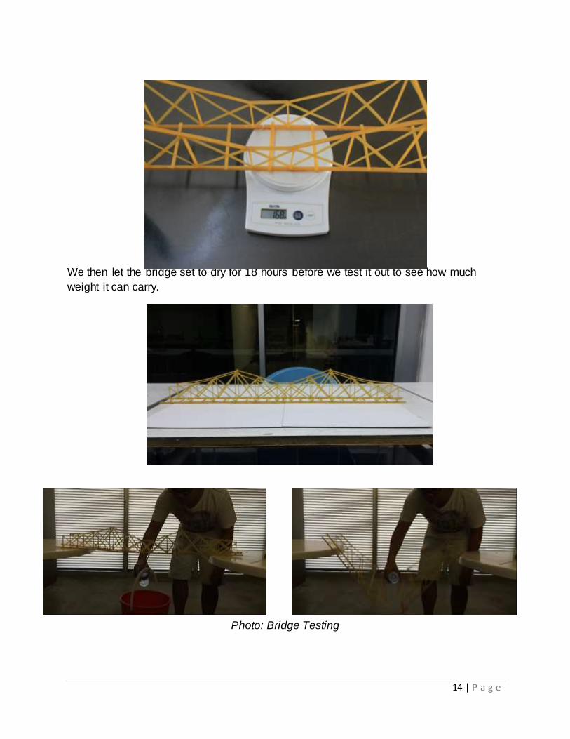
Photo: Final weight of Bridge 168g
We then let the bridge set to dry for 18 hours before we test it out to see how much
weight it can carry.
Photo : The Completed Bridge
Photo: Bridge Testing
15 | P a g e
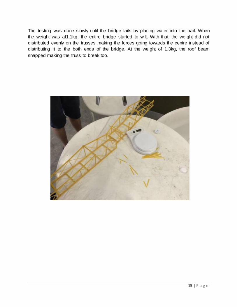
The testing was done slowly until the bridge fails by placing water into the pail. When
the weight was at1.1kg, the entire bridge started to wilt. With that, the weight did not
distributed evenly on the trusses making the forces going towards the centre instead of
distributing it to the both ends of the bridge. At the weight of 1.3kg, the roof beam
snapped making the truss to break too.
Photo: Bridge Truss Failure
16 | P a g e
4.2 Design 2
After the prototype bridge, we then studied and improvised the design
structure and with the aid of our tutorial lecturer Mr. Adib. We redesigned the structure
by taking off the centre joint which was the weak point of our bridge to failing at 1.3kg.
By removing the centre portion, we joint both the tips of the bridge with a straight beam
across each other. With that, the force load will be distributed towards both ends. We
also reduced the number off trusses after studying the load transfer, only keeping those
which are useful. This will then increase our efficiency.
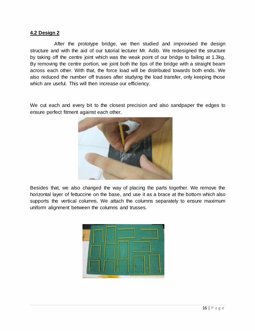
We cut each and every bit to the closest precision and also sandpaper the edges to
ensure perfect fitment against each other.
Photo: Proper Sanding Method
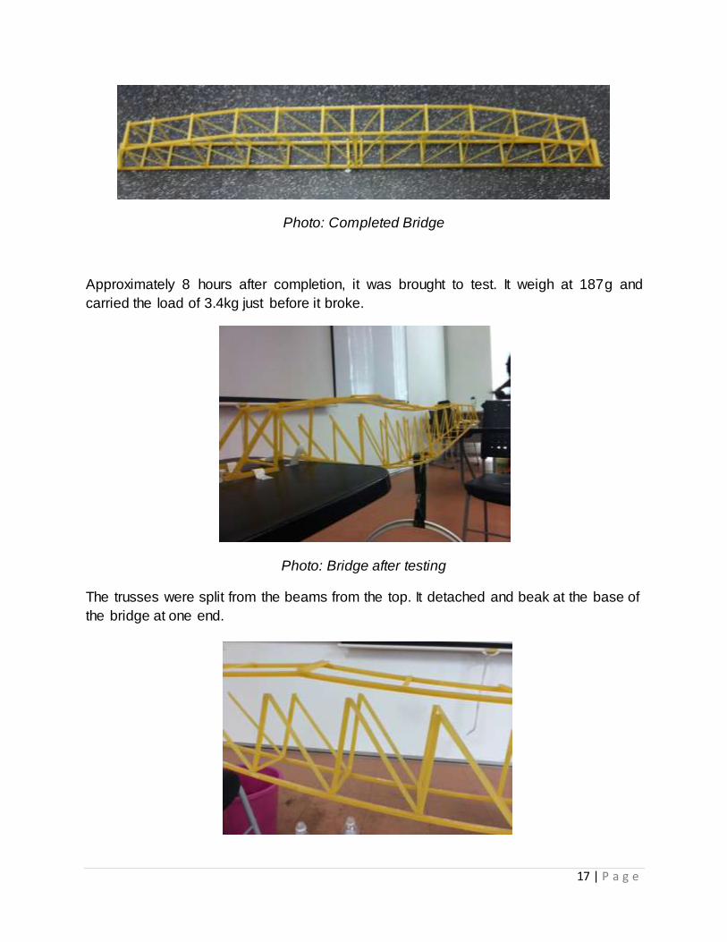
Besides that, we also changed the way of placing the parts together. We remove the
horizontal layer of fettuccine on the base, and use it as a brace at the bottom which also
supports the vertical columns. We attach the columns separately to ensure maximum
uniform alignment between the columns and trusses.
17 | P a g e
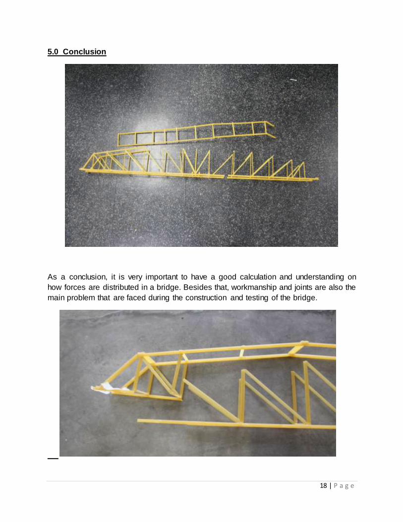
Photo: Completed Bridge
Approximately 8 hours after completion, it was brought to test. It weigh at 187g and
carried the load of 3.4kg just before it broke.
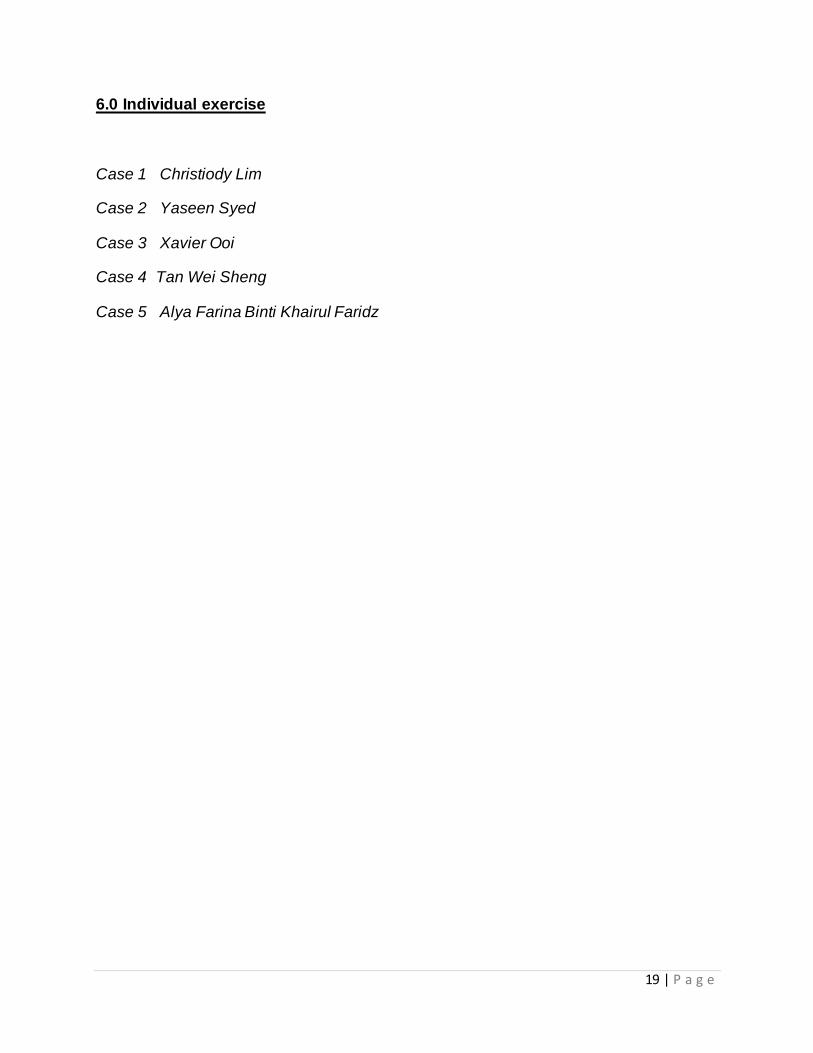
Photo: Bridge after testing
The trusses were split from the beams from the top. It detached and beak at the base of
the bridge at one end.
18 | P a g e
5.0 Conclusion
As a conclusion, it is very important to have a good calculation and understanding on
how forces are distributed in a bridge. Besides that, workmanship and joints are also the
main problem that are faced during the construction and testing of the bridge.
19 | P a g e
6.0 Individual exercise
Case 1 Christiody Lim
Case 2 Yaseen Syed
Case 3 Xavier Ooi
Case 4 Tan Wei Sheng
Case 5 Alya Farina Binti Khairul Faridz
20 | P a g e
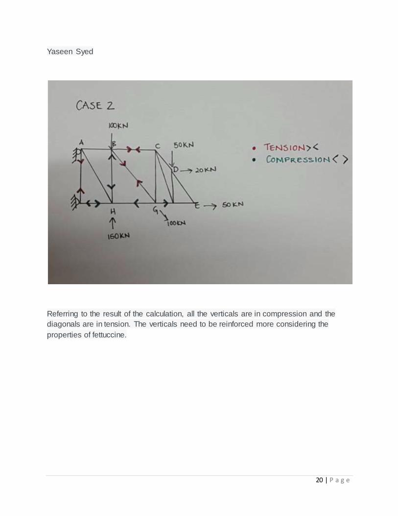
Yaseen Syed
Referring to the result of the calculation, all the verticals are in compression and the
diagonals are in tension. The verticals need to be reinforced more considering the
properties of fettuccine.

21 | P a g e
Alya Farina Binti Khairul Faridz
Analysis:
In reference to the calculations, the trusses which are under compression are those
positioned near or no the centre of the structure, thus weakening the structure
significantly. The forces are exerted firmly on joints C and G, and will most likely cause
buckling when put under the influence of a load. Therefore the joints and trusses in
those areas specifically have to be strengthened considerably to make up for the
compression forces.