BUILDING STRUCTURE WORKS ESTIMATION PROGRAM – BEST’s · limited to the estimation of piling...
16
BUILDING STRUCTURE WORKS ESTIMATION PROGRAM – BEST’s Asmawan Mohd Sarman 1 and Elis Mardzianah Mazlan 2 1, 2 Universiti Malaysia Sabah, Malaysia 1 [email protected] 2 [email protected] ABSTRACT: Building Structure Works Estimation Program – BEST’s has been developed for the use of cost estimation on building structure works such as piling works, excavation works, foundation works, frames works and extension works. The objectives for this project are to develop a building work estimating program, to increase the accuracy of estimation and to store and retrieve the estimation. Methodology for this project development is using the SDLC Waterfall (System Development Life Cycle, also as "System Design Life Cycle") which consists of six stages such as project planning, requirements definition, design, development, integration & test and installation & acceptance. This program was developed based on window application. The system design will describe how the system is implemented and defined. For this estimation program, Use Case Diagram (USD) and Data Flow Diagram (DFD) are used to show the workflow of the object oriented approach. The database system was developed based on the standard schedules of rates from Jabatan Kerja Raya (JKR) year 2007, Malaysia. The user friendly interface and helpful button of the estimation program allow the user to surf the system in a better way. This estimation program is completed with the calculation function, printout function, search and edit of histories estimation function. Users are allowed to store and retrieve estimation data and information. This estimation program hopefully can be useful to help those individual, contractors and company in their project in such that this system will shorten the time usage to do the estimation compare with the old practice. Besides, increase the accuracy of estimation, the usage of this system would enable those contractors can extend their business and compete with other company in building works sector. Keywords: Building Structure Works, Estimation Program, System Design Life Cycle, Use Case Diagram, Data Flow Diagram. 1. INTRODUCTION Building work estimation is the process of predicting the cost of building work start from sub-structure until finishing and external works. Accurate cost estimates are critical to both developers and clients. The estimate cost can be used for generating request for proposals, contract negotiations, scheduling, monitoring and control. The estimating process for construction involves collecting, analyzing, and summarizing all available data pertaining to a project. The data may consist of a rough concept of the gross area or volume of a project, or a set of detailed plans and specifications. The estimated cost for the project is then determined by adding the estimated costs for all of the components or elements of work. Estimating program provide developers, constructors, quantity surveyors and individual client to estimate the cost of building work projects. This program will be developed based on the rate of 2nd INTERNATIONAL CONFERENCE ON BUILT ENVIRONMENT IN DEVELOPING COUNTRIES (ICBEDC 2008) 461
Transcript of BUILDING STRUCTURE WORKS ESTIMATION PROGRAM – BEST’s · limited to the estimation of piling...

BUILDING STRUCTURE WORKS ESTIMATION PROGRAM – BEST’s
Asmawan Mohd Sarman1 and Elis Mardzianah Mazlan2 1, 2 Universiti Malaysia Sabah, Malaysia
1 [email protected] 2 [email protected]
ABSTRACT: Building Structure Works Estimation Program – BEST’s has been developed for the use of cost estimation on building structure works such as piling works, excavation works, foundation works, frames works and extension works. The objectives for this project are to develop a building work estimating program, to increase the accuracy of estimation and to store and retrieve the estimation. Methodology for this project development is using the SDLC Waterfall (System Development Life Cycle, also as "System Design Life Cycle") which consists of six stages such as project planning, requirements definition, design, development, integration & test and installation & acceptance. This program was developed based on window application. The system design will describe how the system is implemented and defined. For this estimation program, Use Case Diagram (USD) and Data Flow Diagram (DFD) are used to show the workflow of the object oriented approach. The database system was developed based on the standard schedules of rates from Jabatan Kerja Raya (JKR) year 2007, Malaysia. The user friendly interface and helpful button of the estimation program allow the user to surf the system in a better way. This estimation program is completed with the calculation function, printout function, search and edit of histories estimation function. Users are allowed to store and retrieve estimation data and information. This estimation program hopefully can be useful to help those individual, contractors and company in their project in such that this system will shorten the time usage to do the estimation compare with the old practice. Besides, increase the accuracy of estimation, the usage of this system would enable those contractors can extend their business and compete with other company in building works sector. Keywords: Building Structure Works, Estimation Program, System Design Life Cycle, Use Case Diagram, Data Flow Diagram.
1. INTRODUCTION
Building work estimation is the process of predicting the cost of building work start
from sub-structure until finishing and external works. Accurate cost estimates are
critical to both developers and clients. The estimate cost can be used for generating
request for proposals, contract negotiations, scheduling, monitoring and control. The
estimating process for construction involves collecting, analyzing, and summarizing
all available data pertaining to a project. The data may consist of a rough concept of
the gross area or volume of a project, or a set of detailed plans and specifications.
The estimated cost for the project is then determined by adding the estimated costs
for all of the components or elements of work. Estimating program provide
developers, constructors, quantity surveyors and individual client to estimate the
cost of building work projects. This program will be developed based on the rate of
2nd INTERNATIONAL CONFERENCE ON BUILT ENVIRONMENT IN DEVELOPING COUNTRIES (ICBEDC 2008)
461

Malaysia’s Jabatan Kerja Raya (JKR) standard. The program will be developing in
English language base with the objective of user friendly to perform the estimation.
One of the greatest advancements in the estimating process has been the
implementation of the computer. The early uses of computers by construction
companies were limited to accounting functions. With advances in micro-
computering, increased knowledge of computer capabilities, and the development of
user-friendly software, construction managers have begun to use computers in
everyday construction operations to make quick and accurate decisions. (Schueette,
1994). The computer’s potential in construction estimating has progressed from its
use as an adding machine to an integrated process of computer-aided design
(CAD), building work estimating software, and job costing software. There is a
variety of estimating computer software programs available. Some simply perform
the mathematics of the estimation process; others integrate the estimating operation
with other functions of the construction process. The program is imperative that the
estimating understand the calculation methods and assumptions used in the
program. Visual basic is one of the most popular programming languages used for
developing Windows-based, Database and Internet applications. Visual Basic has
evolved from the original BASIC language and contains several hundred
statements, functions, and keywords, many of which relate directly to the Windows
GUI. During this project, visual basic programming is used to develop the basic
element of estimating program such as database, quantity takeoff, cost calculation
and bid total of building work estimating program. (Sellappan, 2006)
2. OBJECTIVES
The objectives for this project are to develop a building work estimating program, to
increase the accuracy of estimation, and the program can store and retrieve the
estimation.
3. SCOPE OF STUDY
This project describes a general overview of building work estimating, analysis of
building structure and study of visual basic programming. The program will be
limited to the estimation of piling work, foundation and skeleton frames of building.
All the estimation will base on Malaysia 2006 Jabatan Kerja Raya (JKR) schedule of
rates.
2nd INTERNATIONAL CONFERENCE ON BUILT ENVIRONMENT IN DEVELOPING COUNTRIES (ICBEDC 2008)
462

4. METHODOLOGY
Methodology refers as a specific way of performing an operation that implies precise
deliverables at the end of each stage. Usually the process of the project
development is shown using the SDLC Waterfall (System Development Life Cycle,
also as "System Design Life Cycle") which consists of 6 stages such as project
planning, requirements definition, design, development, integration & test and
installation & acceptance.
Figure 1. SDLC Waterfall
1. Project Planning
The most critical section of the project plan is a listing of high-level product
requirements, also referred to as goals. All of the software product requirements to
be developed during the requirements definition stage flow from one or more of
these goals. The minimum information for each goal consists of a title and textual
description, although additional information and references to external documents
may be included.
2. Requirement Definition
The requirements gathering process takes as its input the goals identified in the
high-level requirements section of the project plan. Each goal will be refined into a
set of one or more requirements. These requirements define the major functions of
the intended application, define operational data areas and reference data areas,
and define the initial data entities.
3. Design Stage
The design stage takes as its initial input the requirements identified in the approved
requirements document. For each requirement, a set of one or more design
elements will be produced as a result of interviews, workshops, and/or prototype
2nd INTERNATIONAL CONFERENCE ON BUILT ENVIRONMENT IN DEVELOPING COUNTRIES (ICBEDC 2008)
463
efforts. Design elements describe the desired software features in detail, and
generally include functional hierarchy diagrams, screen layout diagrams, tab,
pseudocode, and a complete entity-relationship diagram with a full data dictionary.
In this stage, related and suitable module is needed to be design, such as interface
& navigation design, content design, component design and architecture & aesthetic
design. Besides that, suitable buttons, list boxes and toolbars must be allocated in
the interface. Among the interface that will include in this project is piling work,
foundation, skeleton frames details. The content design for this project is to
determine the relationship between each building work.
4. Development Stage
The development stage takes as its primary input the design elements described in
the approved design document. For each design element, a set of one or more
software artifacts will be produced. Software artifacts include but are not limited to
menus, and data management forms, data reporting formats, and specialized
procedures and functions. Appropriate test cases will be developed for each set of
functionally related software artifacts, and an online help system will be developed
to guide users in their interactions with the software.
5. Integration and Test Stage
During the integration and test stage, the software artifacts, online help, and test
data are migrated from the development environment to a separate test
environment. At this point, all test cases are run to verify the correctness and
completeness of the software. Successful execution of the test suite confirms a
robust and complete migration capability.
6. Installation and Acceptance Stage
During the installation and acceptance stage, the software artifacts, online help, and
initial production data are loaded onto the production server. At this point, all test
cases are run to verify the correctness and completeness of the software.
Successful execution of the test suite is a prerequisite to acceptance of the software
by the customer. After customer personnel have verified that the initial production
data load is correct and the test suite has been executed with satisfactory results,
the customer formally accepts the delivery of the software. The primary outputs of
the installation and acceptance stage include a production application, a completed
acceptance test suite, and a memorandum of customer acceptance of the software.
2nd INTERNATIONAL CONFERENCE ON BUILT ENVIRONMENT IN DEVELOPING COUNTRIES (ICBEDC 2008)
464

5. COMPUTER PROGRAMMING LANGUAGE
Programming language is artificial language used to write instructions that can be
translated into machine language and then executed by a computer to control the
behavior of a machine, particularly a computer. Programming languages are used to
facilitate communication about the task of organizing and manipulating information,
and to express algorithms precisely (Schneider, 1999). C programming is an
imperative (procedural) systems implementation language. Its design goals were for
it to be compiled using a relatively straightforward compiler, provide low-level access
to memory, provide language constructs that map efficiently to machine instructions,
and require minimal run-time support. C was therefore useful for many applications
that had formerly been coded in assembly language. The language has become
available on a very wide range of platforms, from embedded microcontrollers to
supercomputers. PHP (PreHypertext PreProgramming) a scripting language used to
create dynamic Web pages.
Visual Basic 6.0 (VB) is an event driven programming language and
associated development environment from Microsoft for its COM programming
model. Visual Basic was derived from BASIC and enables the rapid application
development (RAD) of graphical user interface (GUI) applications, access to
databases using DAO, RDO, or ADO, and creation of ActiveX controls and objects.
Scripting languages such as VBA and VBScript are syntactically similar to Visual
Basic, but perform differently (Halvorson, 1999). In comparison of the existing
computer language, it shows that there are a lot of similar products in the current
software market, each with its own strength and weakness. Visual basic 6.0 is an
ideal language for developing windows-based, database and internet application.
The project will be developed with visual basic 6.0.
6. SYSTEM ANALYSIS AND DESIGN
6.1 System Design
System design will determinate in detail of the exact operational requirements of a
system, resolution of these into file structures and input/output formats, and relation
of each to management tasks and information requirements. In this section, system
design will describe how the system is implemented and defined. Use case diagram
and DFD (Data Flow Diagram) is used to show the workflow of the object oriented
approach.
2nd INTERNATIONAL CONFERENCE ON BUILT ENVIRONMENT IN DEVELOPING COUNTRIES (ICBEDC 2008)
465

6.1.1 Use case Diagram
Figure 2. Use Case Diagrams
Table1. Use Case Functions and Descriptions
Item Use Case No. Functions Descriptions
1 Use Case 1 Home Page This is the first module will show when user run building works estimation program. This module is use to connect to part setting module, main menu module, view history record module, print record module and search and edit module. In this module, user needs to locate building works estimation database with part setting command button. Only a successful and complete setting will be allow user to access the home page menu and run the estimation program.
2 Use Case 2 Part Setting This module is used to identify the location of the database that user need to save for the estimation result. This is a very important step. This step only needs to do in the first time use of building work estimation program. The first time use program without part setting will create error and the estimation program will close down.
3 Use Case 3 Main Menu This module is used to connect the building works estimating function modules such as piling works estimation module, excavation works module, foundation works module and frame works module.
4 Use Case 4 View History Record
This module is used to connect to the building works estimation record database. This is the place where the user can actually view the history estimation record such as the total price of building works item, item code, item description and others.
5 Use Case 5 Search and Edit This module is used to search and edit the previous building works estimation record form the database. User may use the item code to search and edit item detail such as item description, item parameters, item price and JKR standard price.
6 Use Case 6 Print Record This module allow user to view final estimation record and total price of the building works. User may print the building work estimation record here.
7 User Case 7 Piling Works Estimation
This module allow user to select piling works item under the Schedule of Rates for Building Works of JKR standard. The JKR’ unit price will show once piling works item is selected. This module required user to fill up the parameters such as length, quantity, number and custom unit price for calculation. User may
2nd INTERNATIONAL CONFERENCE ON BUILT ENVIRONMENT IN DEVELOPING COUNTRIES (ICBEDC 2008)
466

save the piling works estimation detail to database record.
8 User Case 8 Excavation Works Estimation
This module is similar with User Case 7. User may select the excavation works item under JKR standard. The JKR’ unit price will show once excavation works item is selected. This module required user to fill up the parameters such as quantity, length, width, height, number and custom unit price for calculation. User may save the excavation works estimation detail to database record.
9 User Case 9 Foundation Works Estimation
This module is similar with User Case 7 and 8. User may select the foundation works item under JKR standard. The JKR’ unit price will show once foundation works item is selected. This module required user to fill up the parameters such as quantity, length, width, height, number and custom unit price for calculation. User may save the foundation works estimation detail to database record.
10 User Case 10 Frame Works Estimation
This module is similar with User Case 7, 8, and 9. User may select the frame works item under JKR standard. The JKR’ unit price will show once frame works item is selected. The JKR’ unit price will show once frame works item is selected. This module required user to fill up the parameters such as quantity, length, width, height, number and custom unit price for calculation. User may save the frame works estimation detail to database record.
6.1.2 Data Flow Diagram (DFD)
DFD (Data Flow Diagram) is a chart that traces the movement of data in a computer
system and shows how the data is to be processed.
Figure 3. Data Flow Diagram (DFD)
For first time use, user need to complete the “Part Setting” with located the program
database. After validation of the part name, the user can start building works
estimation by proceed to the main menu with more option such as piling works
estimation, excavation works estimation, foundation works estimation, frame works
estimation and extension works estimation. After the selection on the specific
process, calculation will be done based on the building work item parameters,
custom unit price and JKR standard year 2007. All the detail estimation will stock in
the building works estimation database by clicked “Save” button. User may proceed
to the “Search and Edit” page to change or delete the previous detail of estimation
record such as item description, item parameter or custom unit price. After
completed and satisfied the estimation project, user may proceed to “Print Record”
2nd INTERNATIONAL CONFERENCE ON BUILT ENVIRONMENT IN DEVELOPING COUNTRIES (ICBEDC 2008)
467

page to view the total amount of estimation cost in both custom standard and JKR
standard year 2007. User click “Print” button to print out the final result.
6.1.3 User Interface Design and System Properties
a. Home Page
Figure 4. Home Page Interface
Only the first time use of building works estimation program need to locate
the program database. After validation of the “Part Setting”, the program
will show the “Home Page” and “Part Setting” page will be unloaded. From
the “Home Page” user may process the estimation process with more
option.
Table 2. Home Page Properties
Page Name: Home Page Description: As the first page to allow user process building works estimation. Background: Bitmap
No Tools Label / Caption Dimension Function
1 Command Button Part Setting None To link to "Part Setting" page
2 Command Button Start Building Works Estimation None To link to "Main Menu" page
3 Command Button View History Estimation Record None To link to "Estimation Record" page
4 Command Button Search and Edit Estimation Record None To link to "Search and Edit" page
5 Command Button Print Estimation Record None To link to "Estimation Record" page
6 Command Button Exit None To close down the program
b. Path Setting
Figure 5. Part Setting Interface
User may select and locate the database by using the drive list box, list
box directory and file list box above. This path name is the location of the
database that user need to save data into the database.
2nd INTERNATIONAL CONFERENCE ON BUILT ENVIRONMENT IN DEVELOPING COUNTRIES (ICBEDC 2008)
468

Table 3. Part Setting Properties
Page Name: Part Setting Description: Allow user to locate the estimation database Background: Bitmap
No Tools Label / Caption Dimension Function
1 Drive List Box None None To locate computer driver.
2 List Box Directory None None List and show the content of directory when user double clicks on it.
3 File List Box None None List and show all files of a folder and allow user to select the file.
4 Text Box Part None To show the location of the file user selected.
5 Command Button OK None To locate the file and set as database.
6 Command Button Exit None To close down the program
c. Main Menu
In this page, user can select the specific field such as piling works,
excavation works, foundation works and frame works to perform the
specific estimation. User may return back to the home page by using
command button named “Back to Home Page”.
Figure 6. Main Menu Interface
Table 4. Main Menu Properties
Page Name: Main Menu Description: As a menu to allow user to choose the type of building works Background: Bitmap
No Tools Label / Caption Dimension Function
1 Command Button Piling Works Estimation None To link to "Piling Works Estimation" page
2 Command Button Excavation Works Estimation None To link to "Excavation Works Estimation" page
3 Command Button Foundation Works Estimation None To link to "Foundation Works Estimation" page
4 Command Button Frame Works Estimation None To link to "Frame Works Estimation" page
5 Command Button Extension Works Estimation None To link to "Extension Works Estimation" page
6 Command Button Back to Home Page None To link to “Home Page” page
2nd INTERNATIONAL CONFERENCE ON BUILT ENVIRONMENT IN DEVELOPING COUNTRIES (ICBEDC 2008)
469

d. Building Structure Works Estimation
User may select the building structure works element such as piling works
item from the list box above or fill up own item core and item description.
User is required to fill up the entire yellow color text box for estimation
process. The parameters used in building structure works are varies
depend to the specific element of the works, for example piling works are
length, quantity and number of piling work item.
Figure 7. Piling Works Estimation Interface
Table 5. Piling Works Estimation Properties
Page Name: Piling Works Estimation Description: Allow user to estimate piling works. Background: Bitmap
No Tools Label / Caption Dimension Function
1 List Box Main List Box None
To show the content of sub list box when user select one of the item from main list box.
2 List Box Sub List Box None
To show the content of item list box when user select one of the item from sub list box.
3 List Box Item List Box None List and show the content and allow user to select the file.
4 Text Box Item Code String
Automatically show the item code once user select building works item from item list box.
5 Text Box Item Description String
Automatically show the item description once user select building works item from item list box.
6 Text Box Length Double Allow user to fill up the length of item.
7 Text Box (Behind of length text box ) Quantity Double Allow user to fill up the quantity of item.
8 Text Box Number Double Allow user to fill up the number of item.
9 Label Total Quantity Double Show the result of calculation once user click on “custom unit price” text box.
10 Text Box (Custom) Unit Price Double Allow user to fill up the custom unit price.
11 Label (Custom) Total Double Show total price of custom unit once user click command button “Calculate”
12 Label (JKR standard) Unit Price Double
Show the unit price of JKR standard once user click building works item on item list box.
13 Label (JKR standard) Total Double Show total price of JKR standard once user click command button “Calculate”
14 Command Button Calculate None Active the calculation program code.
15 Command Button Save None Save detail estimation to estimation database.
16 Command Button Back None To link “Main Menu” page.
17 Command Button Home Page None To link to “Home Page” page
2nd INTERNATIONAL CONFERENCE ON BUILT ENVIRONMENT IN DEVELOPING COUNTRIES (ICBEDC 2008)
470

Figure 8. Piling Works Estimation Control Structure
e. Extension Works Estimation
User may select the extension works according the unit calculation of user
needed. There are five types of calculation give which are in quantity
form, length form, mass form, area form and volume form. User are
required to fill up own item core and item description. User is needed to fill
up the entire yellow color text box for estimation process. The parameters
used in extension works are length, width, height, quantity and number of
excavation work item.
Figure 9. Extension Works Estimation Interface
2nd INTERNATIONAL CONFERENCE ON BUILT ENVIRONMENT IN DEVELOPING COUNTRIES (ICBEDC 2008)
471
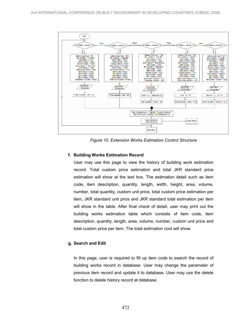
Figure 10. Extension Works Estimation Control Structure
f. Building Works Estimation Record
User may use this page to view the history of building work estimation
record. Total custom price estimation and total JKR standard price
estimation will show at the text box. The estimation detail such as item
code, item description, quantity, length, width, height, area, volume,
number, total quantity, custom unit price, total custom price estimation per
item, JKR standard unit price and JKR standard total estimation per item
will show in the table. After final check of detail, user may print out the
building works estimation table which consists of item code, item
description, quantity, length, area, volume, number, custom unit price and
total custom price per item. The total estimation cost will show.
g. Search and Edit
In this page, user is required to fill up item code to search the record of
building works record in database. User may change the parameter of
previous item record and update it to database. User may use the delete
function to delete history record at database.
2nd INTERNATIONAL CONFERENCE ON BUILT ENVIRONMENT IN DEVELOPING COUNTRIES (ICBEDC 2008)
472

Figure 11. Search and Edit Control Structure
6.1.4 Database Design
Database design is the process of producing a detailed data model of a database.
This contains all the needed logical and physical design choices and physical
storage parameters needed to generate a design in a Data Definition Language. A
fully attributed data model contains detailed attributes for each entity.
Table 6. Database Design View
No Field Name Data Type Field Size
1 EstimateID (Primary Key) AutoNumber Long Integer
2 ItemCode Text 50
3 ItemDescription Text 100
4 Qty Number Double
5 Length Number Double
6 Width Number Double
7 Height Number Double
8 Area Number Double
9 Volume Number Double
10 Number Number Double
11 TotalQty Number Double
12 UnitPriceCust Number Double
13 TotalCust Number Double
14 UnitPriceJKR Number Double
15 TotalJKR Number Double
7. INSTALLATION AND CONFIGURATION
This stage carries development through from design to operation. It involves
programming testing and installation of the required software. After
2nd INTERNATIONAL CONFERENCE ON BUILT ENVIRONMENT IN DEVELOPING COUNTRIES (ICBEDC 2008)
473

implementation, there are necessary ways to run the building works estimation
program. Start by going to the building works estimation program setup folder and
select setup file. Double clicks to run the setup file and the first screen that user
should see is shown in figure below, which welcomes the user to the setup of the
project and press “OK”.
Figure 12. Setup Information
Figure 13 Setup Destination Directories
Choose the default destination directory or change the desired location and
click the button. On the next screen select “Building Works Estimation Program
Project” and click “Continue” to install the setup.
Figure 14. Program Group Box
2nd INTERNATIONAL CONFERENCE ON BUILT ENVIRONMENT IN DEVELOPING COUNTRIES (ICBEDC 2008)
474

Figure 15. Load Bar
The installation will start and user required waiting for the installation to
complete. User may click the “Cancel” button to cancel and quite the installation of
the project. The installation will finish by showing message box “Building Works
Estimation Program Project Setup was completed successfully”.
8. TESTING AND RESULT
In this section, testing and result phase required to perform on the application of
system. Generally testing takes an external perspective of the test object to derive
test cases. These tests can be functional or non-functional, though usually
functional. The test designer selects valid and invalid input and determines the
correct output. This type of test is applicable to all levels of software testing: unit,
integration, functional testing, system and acceptance. Basically, the testing is
performed in Unit Test, Linking Test and System Test. Development of the building
works estimation program is to help those individual and company who want to
prepare the building works estimation and compare between user custom price and
JKR standard year 2007.
9. CONCLUSSION
Usually a good application system requires a very detailed attention and great
creativity in planning the SDLC (System Development Life Cycle). To produce a
good system, selection of the development tools also very important, it will affect the
appearance and acceptance of the system. The workflow of the project should
clearly stated and in the correct order to prevent confusion. In some condition,
sometime even the appearance of a button during the interface design will affect the
overall appearance. Graphic and animation usage should as minimum as possible
to prevent the user from long time waiting for the page to complete loading.
2nd INTERNATIONAL CONFERENCE ON BUILT ENVIRONMENT IN DEVELOPING COUNTRIES (ICBEDC 2008)
475

However, the most important matter in building works estimation is the simplicity and
applicability of the system to the factual cost. Cost estimation program system must
be simple, reliable and flexible. The building works estimation program based on
functional elements helps user to estimate the selected building works using custom
unit price and unit price JKR standard year 2007. This estimation program (Building
Works Estimation Program) can be useful to help those individual and company in
their project in such that this system will shorten the time usage to do the estimation
compare with the old practice. Besides, increase the accuracy of estimation, the
usage of this system would enable those contractors can extend their business and
compete with other company in building works sector.
10. REFERENCES
Ashworth, Allan. 2004. Cost Studies of Buildings, 4th Edition. England: Pearson Education Limited.
Chudley, Roy. 1999. Construction Technology, Third Edition. England: Pearson
Education Limited. Foster Jack Stroud and Harington Raymond. 1994. Mitchell’s Structure and Fabric
Part 2, 5th Edition. England: Addison Wesley Longman Limited. Foster Jack Stroud. 1994. Mitchell’s Structure and Fabric Part 1, 5th Edition.
England: Addison Wesley Longman Limited. Halvorson Michael. 1999. Learn Microsoft Visual Basic 6.0 Now. United States of America: Microsoft Press Holm Len, Schaufelberger John E., Griffin Dennis and Cole Thomas. 2005.
Construction Cost Estimating Process and Practices. United States of America: Pearson Prentice Hall
Pratt David. 1995. Fundamentals of Construction Estimating. United States of
America: Delmar Publishers. Sellappan P. 2006. Visual Basic 6 Programming. Malaysia: Venton Publishing (M)
Sdn Bhd. Schneider David I. 1999. Computer Programming Concepts and Visual Basic.
United States of America: Pearson Custom Publishing. Schuette Stephen D. 1994. Building Construction Estimating. Singapore: McGraw-
Hill Book Co. Spence William P. 1998. Construction Materials, Methods, and Techniques. United
States of America: Delmar Publishers.
2nd INTERNATIONAL CONFERENCE ON BUILT ENVIRONMENT IN DEVELOPING COUNTRIES (ICBEDC 2008)
476