BUILDING SERVICES INSTALLATION - City University
257
27/09/10 Page 1 of 257 Building Services - Rev B BUILDING SERVICES INSTALLATION CU55
Transcript of BUILDING SERVICES INSTALLATION - City University

27/09/10 Page 1 of 257 Building Services - Rev B
BUILDING SERVICES INSTALLATION
CU55
27/09/10 Page 2 of 257 Building Services - Rev B
Contents SECTION 1
PIPEWORK
STEAM PIPELINES Application Pipe: Black Carbon Steel Fittings: Black Unions: Black: 8 - 25 Mm Flanges: Forged Steel: 15 Mm & Above Screwed Joints Flanged Joints CONDENSE PIPELINES Application Pipe: Black Carbon Steel Fittings: Black Unions: Black: 8 - 40 Mm Flanges Screwed Joints Flanged Joints LTHW HEATING PIPELINES Application Pipe: Black Carbon Steel Fittings: Black Unions: 8 - 50 Mm Flanges: Forged Steel: 15 Mm & Above Screwed Joints Flanged Joints CHILLED WATER AND GLYCOL PIPELINES Application Pipe: Black Carbon Steel Fittings: Black Unions: 8 - 50 Mm Flanges: Forged Steel: 15 Mm & Above Flanged Joints HOT WATER PIPELINES - INTERNAL DOMESTIC
Tank And Mains Cold Water Pipelines - Internal Domestic Application Pipe Fittings And Unions Flanges Flange Gaskets

27/09/10 Page 3 of 257 Building Services - Rev B
FIRE MAIN PIPELINES - INTERNAL Application Pipe: Galvanised Carbon Steel: 15-100 Mm Fittings: Galvanised: 15 - 100 Mm Unions: 15 - 50 Mm Flanges: Forged Steel, Raised Face: 15 - 100 Mm Gaskets MAINS COLD WATER PIPELINES - EXTERNAL BURIED (MDPE BLUE)
Application: Potable Water Pipe: Blue Medium Density Polyethylene (Mdpe) Fittings: Blue Polyethylene Mdpe Flanges And Adaptors Flange Gaskets FEEDS, VENTS AND DRAINS Application Pipe Fittings And Unions Flanges Flanged Joints OVERFLOW AND WARNING PIPES
NATURAL GAS PIPELINES - INTERNAL
Application Pipe: Black Carbon Steel Fittings: Black Unions: 8 - 40 Mm Flanges: Forged Steel, Raised Face: 15 Mm & Above Flange Gaskets NATURAL GAS PIPELINES - EXTERNAL BURIED Application Pipe Fittings Adaptors Flanges Flange Gaskets COMPRESSED AIR PIPELINES Application Pipe: Copper: 6 - 10 mm Fittings : Brass: 6 - 10 mm Pipe: Galvanised Carbon Steel: 8 - 100 mm Fittings: Galvanised: 8 - 100 mm Unions: 8 - 50 mm Flanges: Forged Steel: 15 - 100 mm Flanged Joints
27/09/10 Page 4 of 257 Building Services - Rev B
VACUUM PIPELINES
Application Pipe: 15-54 mm Fittings And Unions: 15-54 mm NITROGEN PIPELINES Application Pipe: 15-54 mm Fittings And Unions: 15-54 mm NITROGEN PIPELINES Application Pipe: 6-10 mm Pipe: 15-54 mm Fittings : 6 - 10 mm Fittings And Unions: 15-54 mm (Up To 2.1 Bar G) Fittings And Unions: 15-54 mm (Up To 10 Bar G) WASTE PIPELINES - POLYPROPYLENE Application Pipe: 38-102 mm Fittings: 38-102 mm Sink Traps: 38 mm Drip Cups BURIED PIPELINES - TRENCHING External Pipelines - Building Entry Draw-Off Taps And Ball Valves PIPEWORK WELDING AND BRAZING Standards And Tests Production Work TESTING OF WELDING Application PIPELINES INSTALLATION - GENERAL Pipe Runs And Gradients PIPEWORK CLEARANCE AND SEGREGATION PIPE SLEEVES AND COVER PLATES EXPANSION, ANCHORS AND GUIDES PIPEWORK SUPPORTS Intervals Between Support Centres For Steel Pipework Intervals Between Support Centres For Copper Pipework Intervals Between Support Centres For Abs & Pvc

27/09/10 Page 5 of 257 Building Services - Rev B
PIPEWORK VENTING AND DRAINING EQUIPMENT VENTING AND DRAINING ELECTRICAL PLANT ROOMS
FLUSHING OUT, DRAINING AND REFILLING STANDARD REFERENCES
27/09/10 Page 6 of 257 Building Services - Rev B
SECTION 2 VALVES STEAM Applications Globe Valves: Screwed: 15-25 mm Globe Valves: Flanged: 15-50 mm Globe Valves: Socket Weld: 15-50 mm Stop Valves: Flanged: 65-300 mm Check Valves: Screwed: 15-25 mm Check Valves: Flanged: 15-25 mm Check Valves: Flanged: 25-100 mm Check Valves: Flanged: 100-300 mm Strainers: Screwed: 15-25 mm Strainers: Socket Weld: 15-50 mm Strainers: Flanged: 15-50 mm Strainers: Flanged: 65-300 mm Air Vents Vacuum Breakers Pressure Reducing Valves: Screwed: 15-25 mm Pressure Reducing Valves: Flanged: 15-50 mm Pressure Reducing Valves: Flanged: 50-100 mm Pressure Reducing Valve Sets Separators: Screwed: 15-25 mm Separators: Flanged: 15-150 mm Steam Trap Sets Trap Sets, Thermostatically Controlled And General Plant Equipment
Requirements Steam Humidifiers - Direct Injection Type CONDENSE Application Ball Valves: Screwed: 15-50 mm Ball Valves: Flanged: 50-100 mm Check Valves: Screwed: 15-50 mm Check Valves: Flanged: 15-100 mm Check Valves: Flanged: 100-300 mm Strainers: Screwed: 15-50 mm Strainers: Flanged: 15-200 mm Strainers: Flanged: 200-300 mm LOW TEMPERATURE HOT WATER Application Ball Valves: Screwed: 15-50 mm Butterfly Valves: Flanged: 50-150 mm General Pipeline Isolation Only Equipment & System Isolation Check Valves: Screwed: 15-50 mm Check Valves: Flanged: 65-300 mm Strainers: Screwed: 15-50 mm Strainers: Flanged: 50-300 mm Radiator Valves: Matt Finish (Where Enclosed)

27/09/10 Page 7 of 257 Building Services - Rev B
LOW TEMPERATURE HOT WATER CONTINUED… Radiator Valves: Chromium Plated (Where Exposed) Radiator Valves - Nickel Plated Finish To Match Hattersley Trv's) Thermostatic Radiator Valves CHILLED WATER AND GLYCOL PIPELINES Application Ball Valves: Screwed: 15-50 mm Butterfly Valves: Flanged: 50-150 mm General Pipeline Isolation Only Equipment & System Isolation Check Valves: Screwed: 15-50 mm Check Valves: Flanged: 65-300 mm Strainers: Screwed: 15-50 mm Strainers: Flanged: 50-300 mm HOT WATER - INTERNAL DOMESTIC COLD WATER - INTERNAL DOMESTIC43
Application Ball Valves: Screwed: 15-50 mm Wedge Gate Valves: Flanged: 65-300 mm Servicing Valves Check Valves: Screwed: 15-50 mm Check Valves: Flanged: 50-300 mm Strainers: Screwed: 15-50 mm Strainers: Flanged: 15-100 mm Pressure Regulating Valve MAINS COLD WATER Application Principal Stop Valves ISOLATING VALVES Servicing Valves: 15-54 mm Check Valves: Screwed: 15-50 mm Check Valves: Flanged: 65-300 mm Strainers: Screwed: 15-50 mm Strainers: Flanged: 15-100 mm Float Operated Valves - Small Cisterns Float Operated Valves - Large Cisterns FIRE MAINS INSTALLATIONS Application Wedge Gate Valves: Screwed: 15-50 mm Wedge Gate Valves: Flanged: 65-150 mm Check Valves: Screwed: 15-50 mm Check Valves: Flanged: 65-150 mm Strainers: Screwed: 15-50 mm Strainers: Flanged: 65-150 mm Fire Hydrant Valves - Underground NATURAL GAS Application Ball Valves: Screwed: 15-50 mm Lubricated Plug Valves

27/09/10 Page 8 of 257 Building Services - Rev B
PROPANE Application Isolating Valves: Screwed: 8-40 mm VACUUM Application Isolating Valves: Screwed: 8-40 mm Isolating Valves: Flanged: 50-150 mm COMPRESSED AIR Application Isolating Valves: Screwed: 8-40 mm Isolating Valves: Flanged: 50-150 mm AUTOMATIC AIR VENTS. AIR COCKS THREE-WAY GLAND VENT COCKS DRAIN COCKS TEST POINTS HANDWHEEL LOCKING DEVICES THERMOMETERS General Stem Thermometers Dial Thermometers ALTITUDE AND PRESSURE/VACUUM GAUGES General Altitude And Pressure Gauges Pressure And Vacuum Gauges SAFETY AND RELIEF VALVES Steam And Compressed Air Water And Glycol FLOW MEASUREMENT AND REGULATION Application One Valve System Two Valve System INSTALLATION QUALITY ASSURANCE BRITISH STANDARDS AND CODES OF PRACTICE
27/09/10 Page 9 of 257 Building Services - Rev B
SECTION 3 GAS CYLINDER MANIFOLDS AND DISTRIBUTION PIPEWORK
General Inert Gas systems shall incorporate as a minimum the following components
Special Gas systems in addition to the above components shall have the following items fitted
INERT GASES PIPELINES -NITROGEN, CARBON DIOXIDE, HELIUM, ARGON & COMPRESSED AIR
Application Pipe : 6-10 mm Pipe : 12-54 mm Fittings : 6-10 mm Fittings : 12-54 mm Valves : 6-10 mm Valves : 15-42 mm SPECIAL GASES PIPELINES -HYDROGEN, OXYGEN, METHANE & ISOBUTANE
Application Pipe : 6-10 mm Pipe : 12-54 mm Fittings : 6-10 mm Fittings : 12-54 mm Valves : 6-10 mm Valves : 15-42 mm SPECIAL GASES PIPELINES -AMMONIA Application Fittings : 6-10 mm (imperial equivalent) Valves : 6-10 mm (imperial equivalent) TESTING AND INSPECTION PROPANE PIPELINES Application Pipe: 6-10 mm Fittings: Internal, 6-10 mm Valves: 6-10 mm Soundness Testing Purging Of Pipework INSTALLATION OF PIPES PIPEWORK SUPPORTS IDENTIFICATION OF PIPEWORK REFERENCE DOCUMENTS
27/09/10 Page 10 of 257 Building Services - Rev B
SECTION 4
DUCTWORK (GALVANISED SHEET STEEL) Introduction DUCTWORK CLASSIFICATION DUCTWORK (GSS) Rectangular Ducts Circular Ducts General HANGERS AND SUPPORTS ACCESS OPENINGS AND INSPECTION COVERS TEST HOLES VOLUME CONTROL DAMPERS Dampers For General Purpose Dampers On Supply And Extract Terminals SELF-CLOSING (NON-RETURN) DAMPERS FIRE/SMOKE DAMPERS FLEXIBLE DUCTS FLEXIBLE JOINT CONNECTIONS CONNECTIONS TO BUILDER'S WORK EXTERNAL DUCTWORK ACOUSTIC LININGS AND TREATMENT PROTECTIVE FINISHES Mild Steel Ductwork Sections External Ductwork IDENTIFICATION OF DUCTWORK AIR LEAKAGE TESTING DUCTWORK CLEANING AND FUMIGATION STANDARDS STANDARDS REFERENCES

27/09/10 Page 11 of 257 Building Services - Rev B
SECTION 5 DUCTWORK (P.V.C.)
Introduction PLASTICS DUCTWORK P.V.C. DUCTWORK SPECIFICATION HANGERS AND SUPPORTS ACCESS OPENINGS AND INSPECTION COVERS TEST HOLES VOLUME CONTROL DAMPERS P.V.C. Dampers For General Purpose Dampers For Safety Cabinet/Hepa Filter Isolation
FIRE/SMOKE DAMPERS Fire/Smoke Dampers In Fume Cupboard Extract Ductwork Fire Dampers For Safety Cabinet Ductwork FLEXIBLE JOINTS CONNECTIONS TO BUILDER'S WORK EXTERNAL DUCTWORK Reinforcement Of External Pvc Ductwork Weathering Cravats Vertical Discharge Stacks ACOUSTIC LININGS AND TREATMENT PROTECTIVE FINISHES Internal Mild Steel Sections External Mild Steel Sections IDENTIFICATION OF DUCTWORK AIR LEAKAGE TESTING DUCTWORK CLEANING AND FUMIGATION STANDARDS REFERENCES
27/09/10 Page 12 of 257 Building Services - Rev B
SECTION 6 THERMAL INSULATION General Extent Of Works Applicable Standards Testing Prior To Application Preparation Materials Movement Restrictions On Use Of Materials Materials Excluded Asbestos SCOPE OF WORKS Energy Conservation And Condensation Personnel Protection Frost Protection Surface Condensation General Schedule Of Items To Be Thermally Insulated (Not by way of limitation)
MATERIALS General Requirements Insulation Thicknesses Insulation Of Stainless Steel Pipes And Ducts PROPERTIES OF INSULATING MATERIALS Fibrous Insulation – Material Reference (as table) Phenolic Foam – Material Reference K Flexible Closed Cell Insulation – Material Reference N VAPOUR BARRIERS Material Reference Vb1 CLADDING MATERIALS Aluminium Cladding – Material Reference C1 ‘Aluzink’ Cladding - Material Reference C2 ‘Plastisol’ Cladding – Material Reference C3 Pib Cladding - Material Reference C4 TRACE HEATING General Power Supply Construction Installation Suppliers INSTALLATION (PIPES AND DUCTS) General Duct Insulation Duct Supports Pipe Insulation Pipe Supports Protection Of Insulation For Maintenance Access Static Electricity

27/09/10 Page 13 of 257 Building Services - Rev B
INSTALLATION (PIPES AND DUCTS) CONTINUED Hot Surfaces Cold Surfaces Thermal Expansion And Contraction Ductwork Access Doors CISTERN, TANK, CYLINDER AND CALORIFIER INSULATION
Cisterns And Tanks Vessels And Calorifiers (General Requirements) Vessels And Calorifiers (Hot) Vessels And Calorifiers (Cold) Feed And Vent Pipes PAINTING Painting (General) Painting Ferrous Metal Parts IDENTIFICATION OF ALL SERVICES General Pipework Installations Ductwork Installations Equipment Hazard Warning Signs THERMAL INSULATION SELECTION SCHEDULES Insulating Materials Vapour Barriers Cladding And Finishes INSULATION THICKNESSES Steam Systems Condense Systems Lthw, Domestic Hot Water & Heat Recovery Systems Chilled Water & Glycol/Water Systems Cold Water & Condenser Cooling Water Services Ductwork Conveying Warmed Air Ductwork Conveying Cold Air

27/09/10 Page 14 of 257 Building Services - Rev B
SECTION 7 AIR HANDLING EQUIPMENT Packaged Air Handling Units MIXING SECTIONS AIR FILTERS Panel Filters Bag Or Extended Surface Type Filters High Efficiency Particulate Air (Hepa) Filters HOT WATER AIR HEATER BATTERIES ELECTRIC AIR HEATER BATTERIES STEAM AIR HEATER BATTERIES CHILLED WATER AIR COOLER BATTERIES DIRECT-EXPANSION REFRIGERANT AIR COOLER BATTERIES
HUMIDIFIERS FAN SECTIONS CENTRIFUGAL FANS (STEEL) CENTRIFUGAL FANS (PVC) AXIAL FLOW FANS PROPELLER FANS TOILET EXTRACT FANS FILTER SPECIFICATION SHEETS
27/09/10 Page 15 of 257 Building Services - Rev B
SECTION 8 NOISE AND VIBRATION CONTROL General Requirements INTERNAL NOISE RATINGS NOISE CONTROL EQUIPMENT Rectangular Absorptive Acoustic Attenuators Minimum Permissible Thickness Of Attenuator Side Panels Flange Types To Be Used For Attenuators (proprietary flanges to be specified to match ductwork flanges)
Cylindrical Absorptive Acoustic Attenuators Acoustic Cross Talk Attenuators Acoustic Duct Lagging Acoustic Louvres VIBRATION CONTROL EQUIPMENT Vibration Isolators, General Helical Spring Vibration Isolators Rubber Or Neoprene Vibration Isolators Helical Spring Vibration Isolation Hangers Rubber, Neoprene Or Glass Fibre Vibration Isolation Hangers Spring Isolated Inertia Bases Neoprene Pad Isolated Inertia Bases Flexible Connectors PENETRATIONS IN BUILDING FABRIC Summary Specification For Acoustic Test Equipment Measurement Of System's Noise In Internal Areas

27/09/10 Page 16 of 257 Building Services - Rev B
SECTION 9 TESTING AND COMMISSIONING General Commissioning Records Labour, Materials And Other Provisions Specialist Commissioning Engineer Commissioning Method Statement Rectification Of Defects Reports And Records Witnessing And Notification DEFINITIONS TESTING AT WORKS TESTING AT SITE General Concealed Sections Of Work Pressure And Leakage Testing Thermal Expansion Tests Protection Of System Equipment Draining After Testing STATIC PRESSURE TESTING Pipework Distribution Systems Steam, Condensate, Heating, Chilled Water And Glycol Pipework, Hot Water, Tank And Mains
Cold Water (Internal Domestic), Demineralised Water Underground Pipework Generally Mains Cold Water Pipelines (External Buried) Fire Main Risers Natural Gas Pipework General Service Compressed Air And Nitrogen Pipework Vacuum Pipework Gas Cylinder Pipework Refrigeration Systems Plant And Equipment Testing INSTALLATION OF COMMISSIONABLE SYSTEMS General Installation - Static Completion IDENTIFICATION AND LABELLING Access Panels Valve Labels Manufacturer's Labels Plant And Equipment Labels Wall Charts COMMISSIONING PROCEDURES Commissioning Codes Preliminary Checks - Water Distribution Preliminary Checks - Air Distribution Setting To Work And Regulation - Water Distribution Setting To Work And Regulation - Air Distribution
27/09/10 Page 17 of 257 Building Services - Rev B
COMMISSIONING PROCEDURES CONTINUED Commissioning Refrigeration Systems Commissioning Automatic Control Systems Heat Testing PERFORMANCE AND ACCEPTANCE TESTING SOUND LEVEL MEASUREMENTS COMMISSIONING AND TESTING REPORT Report Content Air Handling Equipment Commissioning Sheets Exhaust/Extract Fan Commissioning Sheets Diffusers, Grilles And Registers Commissioning Sheets Test Code Drawing For Air Systems Water System Commissioning Sheets Pump Commissioning Sheets Heating And Cooling Coil, Run-Around Coil, Air & Water Plate Heat Exchangers And Heat Wheel Commissioning Sheets
Test Code Drawing For Water Systems PERFORMANCE AND ACCEPTANCE TEST RESULTS Approvals RECORD DRAWINGS OPERATING AND MAINTENANCE INSTRUCTIONS INSTRUCTIONS TO EMPLOYER'S STAFF SPARES, TOOLS AND CONSUMABLES PRACTICAL COMPLETION OF THE WORKS REFERENCE DOCUMENTS
27/09/10 Page 18 of 257 Building Services - Rev B
SECTION 1
PIPEWORK
27/09/10 Page 19 of 257 Building Services - Rev B
STEAM PIPELINES Application Steam up to 10.5 bar g, 186OC. Joints in pipework up to 50 mm conveying steam at up to 3.5 bar gauge and not concealed may be either welded or screwed. All other joints shall be welded. Pipe sizes 90 mm (3½"), 125 mm (5") and odd sizes in multiples of 50 mm (2") must not be used. Pipework connections to steam fed equipment shall be configered to gravity drain so as to maintain the equipment and interconnecting steam and condense pipework free of condense at all loads. Where this is not be possible an alternative arrangement may be acceptable with the permission and approval of the Engineer. Pipe: Black Carbon Steel Screwed or plain ends to BS EN 10255:2004, heavy grade (Table 5/red band), screwed ends BS EN 10226-1:2004 taper, black varnished finish. For nominal sizes (DN) 150 mm and above plain ends to BS EN 10217-1:2002, grade ERW 410/430, self-colour with protective oil or varnish finish. Dimensions to BS EN10220:2002, Table 1 and minimum wall thicknesses DN 150 and DN 200 - 8.0 mm thick; DN 250 - 8.8 mm; DN 300 to DN 450 - 10.0 mm. Fittings: Black Wrought steel to BS 1740 seamless, heavy grade, screwed ends BS EN 10226-1:2004 taper, self-colour with protective oil or varnish finish. Carbon steel butt welding pattern to BS EN 10253-2:2007 Part 1, of equal thickness to the pipe, grade ERW 410/430, self-colour with protective oil or varnish finish. Unions: Black: 8 - 25 mm Malleable cast iron to BS 143, navy pattern bronze to bronze spherical seats, screwed ends BS EN 10226-1:2004 taper, self-colour with protective oil or varnish finish. Flanges: Forged Steel: 15 mm & Above Screwed boss type to EN 1092, PN16, raised face type B, screwed BS EN 10226-1:2004 taper, self-colour with protective oil or varnish finish. Weld-neck and slip-on welding types to EN 1092, PN16, raised face type B, self-colour with protective oil or varnish finish. Screwed Joints
27/09/10 Page 20 of 257 Building Services - Rev B
Where screwed joints are used, the male component shall be taper threaded to BS EN 10226-1:2004 and the jointing shall be PTFE tape to BS 5292 Type C and to BS 4375 unless otherwise indicated. Flanged Joints Flange joints shall be made with gaskets of impregnated graphite with perforated stainless steel sheet reinforcement fitted inside the bolt circle. They shall be of a grade and thickness suitable for the temperature, pressure and operating conditions of the service. Gaskets shall be installed in accordance with the manufacturers instructions and torque settings for flange bolts (general rule is to compress the gasket to half its original thickness). Hexagon head metric carbon steel bolts of the correct diameter complete with one nut shall be used with flanges to EN 1092. Where flanged connections are made to equipment and valves with aluminium, copper alloy or cast iron flat face flanges to EN 1092, the raised face of the mating flange to EN 1092 shall be removed and the resulting machined surface shall comply with the tolerances quoted in EN 1092. The flange gasket shall cover the full face of the flange.

27/09/10 Page 21 of 257 Building Services - Rev B
CONDENSE PIPELINES Application Condense systems up to 7.0 bar g, 170OC. The condense pipeline shall commence at the steam trap downstream isolating valve. Joints in pipework up to 50 mm conveying steam condense at up to 3.5 bar gauge and not concealed may be either welded or screwed. All other joints shall be welded. Pipe sizes 90 mm (3½"), 125 mm (5") and odd sizes in multiples of 50 mm (2") must not be used. Pipework connections to steam fed equipment shall be configered to gravity drain so as to maintain the equipment and interconnecting steam and condense pipework free of condense at all loads. Where this is not be possible an alternative arrangement may be acceptable with the permission and approval of the Engineer. Pipe: Black Carbon Steel API 5L grade B seamless tube, DN 15 to 40 schedule 80 screwed ends BS EN 10226-1:2004 taper, DN 50 to DN 150 schedule 40 bevelled ends , DN 200 to DN 300 bevelled ends, self-colour with protective oil or varnish finish. Fittings: Black Wrought steel to BS 1740 seamless, heavy grade, screwed ends EN 10226-1:2004 taper, self-colour with protective oil or varnish finish. Carbon steel butt welding pattern to BS EN 10253-2:2007 seamless, of equal thickness to the pipe, grade ERW 410/430, self-colour with protective oil or varnish finish. Unions: Black: 8 - 40 mm Wrought steel to BS 1740 seamless, screwed ends BS EN 10226-1:2004 taper, self-colour with protective oil or varnish finish. Flanges Screwed boss type to EN 1092, PN16, raised face type B, screwed BS EN 10226-1:2004 taper, self-colour with protective oil or varnish finish. Weld-neck and slip-on welding types to EN 1092, PN16, raised face type B, self-colour with protective oil or varnish finish. Screwed Joints Where screwed joints are used, the male component shall be taper threaded to BS EN10226-1:2004 and the jointing shall be PTFE tape to BS 5292 Type C and to BS 4375 unless otherwise indicated.
27/09/10 Page 22 of 257 Building Services - Rev B
Flanged Joints Flange joints shall be made with gaskets of impregnated graphite with perforated stainless steel sheet reinforcement fitted inside the bolt circle. They shall be of a grade and thickness suitable for the temperature, pressure and operating conditions of the service. Gaskets shall be installed in accordance with the manufacturers instructions and torque settings for flange bolts (general rule is to compress the gasket to half its original thickness). Hexagon head metric carbon steel bolts of the correct diameter complete with one nut shall be used with flanges to BS EN1092. Where flanged connections are made to equipment and valves with aluminium, copper alloy or cast iron flat face flanges to BS EN1092, the raised face of the mating flange to BS EN1092 shall be removed and the resulting machined surface shall comply with the tolerances quoted in BS EN1092. The flange gasket shall cover the full face of the flange.

27/09/10 Page 23 of 257 Building Services - Rev B
LTHW HEATING PIPELINES Application LTHW up to 3.5 bar g, 95OC. Joints in pipework up to and including 50 mm and not concealed, may be either welded or screwed. All other joints and all joints 65 mm and over shall be welded. Pipe sizes 90 mm (3½"), 125 mm (5") and odd sizes in multiples of 50 mm (2") must not be used. Pipe: Black Carbon Steel Screwed and plain ends to BS EN10255:2004, heavy grade (Table 5/red band), screwed ends BS EN10266:2004 taper, black varnished finish. For nominal sizes (DN) 150 mm and above plain ends to BS EN10217-1:2002, grade ERW 410/430, self-colour with protective oil or varnish finish. Dimensions to BS EN10220:2002 with minimum wall thicknesses DN 150 and DN 200 - 8.0 mm thick; DN 250 - 8.8 mm; DN 300 to DN 450 - 10.0 mm. Fittings: Black Malleable cast iron, reinforced pattern to BS 143 & 1256, screwed ends BS EN10266:2004 taper, self-colour with protective oil or varnish finish. Carbon steel butt welding pattern to BS EN10253-2:2007, of equal thickness to the pipe, grade ERW 410/430, self-colour with protective oil or varnish finish. Unions: 8 - 50 mm Malleable cast iron to BS 143, navy pattern bronze to bronze spherical seats, screwed ends BS EN10266:2004 taper, self-colour with protective oil or varnish finish. Flanges: Forged Steel: 15 mm & Above Screwed boss type to BS EN1092:2003 PN6, raised face type B, screwed BS EN 10266:2004 taper, self-colour with protective oil or varnish finish. Weld-neck and slip-on welding types BS EN1092:2003, PN6, raised face type B, self-colour with protective oil or varnish finish. Screwed Joints Where screwed joints are used, the male component shall be taper threaded to BS EN10266:2004 and the jointing shall be PTFE tape to correct standards unless otherwise indicated.
27/09/10 Page 24 of 257 Building Services - Rev B
Flanged Joints Flange joints shall be made with compressed non-asbestos fibre gaskets inside the bolt circle. They shall be of a grade and thickness suitable for the temperature, pressure and operating conditions of the service. Hexagon head carbon steel metric bolts of the correct diameter shall be used with flanges to BS EN 1092-3:2003. Where flanged connections are made to equipment and valves with copper alloy or cast iron flat face flanges to BS EN 1092-3:2003, the raised face of the mating flange to BS EN 1092-3:2003 shall be removed and the resulting machined surface shall comply with the tolerances quoted in BS EN 1092-3:2003. The flange gasket shall cover the full face of the flange.
27/09/10 Page 25 of 257 Building Services - Rev B
CHILLED WATER AND GLYCOL PIPELINES Application Chilled water and glycol/water mixtures up to 6 bar g, -6OC to 15OC. Joints in pipework up to 50 mm and where not concealed may be either welded or screwed. All other joints and all joints 65 mm and over shall be welded. Pipe sizes 90 mm (3½"), 125 mm (5") and odd sizes in multiples of 50 mm (2") must not be used Pipe: Black Carbon Steel Screwed or plain ends to BS EN10255:2004, heavy grade (Table 5/red band), screwed ends BS EN10266:2004 taper. For nominal sizes (DN) 150 mm and above plain ends to BS EN 10216-1:2006, grade ERW 410/430, self-colour with protective oil or varnish finish. Dimensions to BS EN10220:2002 with minimum wall thicknesses DN 150 and DN 200 - 8.0 mm thick; DN 250 - 8.8 mm; DN 300 to DN 450 - 10.0 mm. Pipe shall have all mill scale, corrosion and grease removed and be protected by zinc phosphate anti-corrosion primer paint at manufacturer's works. Fittings: Black Malleable cast iron, reinforced pattern to BS 143 & 1256, screwed ends BS EN 10266:2004 taper, self colour with protective oil or varnish finish. Carbon steel butt welding pattern to BS EN 10253-2:2007, of equal thickness to the pipe, grade 410/430, self colour with protective oil or varnish finish. Unions: 8 - 50 mm Malleable cast iron to BS 143, navy pattern bronze to bronze spherical seats, screwed ends BS 21 taper, self colour with protective oil or varnish finish. Flanges: Forged Steel: 15 mm & Above Screwed boss type to BS EN1092-3:2003, PN10, raised face type B, screwed BS EN 10266:2004 taper, self-colour with protective oil or varnish finish. Weld-neck and slip-on welding types to BS EN1092-3:2003, PN10, raised face type B, self-colour with protective oil or varnish finish. Flanged Joints

27/09/10 Page 26 of 257 Building Services - Rev B
Flange joints shall be made with compressed non-asbestos fibre gaskets inside the bolt circle. They shall be of a grade and thickness suitable for the temperature, pressure and operating conditions of the service. Hexagon head carbon steel metric bolts of the correct diameter shall be used with flanges to BS EN 1092-3:2003. Where flanged connections are made to equipment and valves with copper alloy or cast iron flat face flanges. The raised face of the mating flange shall be removed and the resulting machined surface shall comply with the tolerances quoted. The flange gasket shall cover the full face of the flange.
27/09/10 Page 27 of 257 Building Services - Rev B
HOT WATER PIPELINES - INTERNAL DOMESTIC TANK AND MAINS COLD WATER PIPELINES - INTERNAL DOMESTIC Application Domestic hot and cold water systems up to 6 bar g, 65OC. Joints in pipework up to and including 54 mm and where not concealed shall be capillary soldered fittings and unions. All other joints and all joints 65 mm and over shall be brazed fittings and flanges. All pipe and capillary fittings shall have the British Standard Kitemark. Pipe Copper type C106, non-arsenical and deoxidised to BS EN1057:2006 R250, half hard. Fittings And Unions Capillary type, non-dezincifiable copper or copper alloy to BS EN 1254-1:1998, 99/1 tin/copper integral solder ring pattern. Fittings or fabrications produced from copper type C106, brazing bends and fittings from tube socketed for capillary brazing with silver alloy brazing metal type. Belled ends formed using copper to BS EN1057:2006 R230. Flanges Mild steel flange/copper alloy centre piece, capillary type to BS EN 1092-3:2003, 40% silver alloy brazing metal type AG20 and protected against electrolytic action and corrosion. Flange Gaskets Suitable for potable hot and cold water 6 bar g and 65OC.
27/09/10 Page 28 of 257 Building Services - Rev B
FIRE MAIN PIPELINES – INTERNAL Application Fire hose reel systems up to 10 bar g, 10OC Joints in galvanised pipework up to and including 100 mm shall be screwed, BS EN10266:2004 taper threads. Exposed threads of screwed galvanised pipe shall be painted with 'cold galvanising' solution. Pipe sizes 90 mm (3½"), 125 mm (5") and odd sizes in multiples of 50 mm (2") must not be used. Pipe: Galvanised Carbon Steel: 15-100 mm Screwed ends to BS EN 10255:2004, heavy grade (Table 5/red band), screwed ends BS EN 10266:2004 taper, galvanised finish. Fittings: Galvanised: 15 - 100 mm Wrought steel, heavy grade to BS EN 10241:2000, screwed ends BS EN 10266:2004 taper, galvanised finish. Unions: 15 - 50 mm Malleable cast iron to BS 143, navy pattern bronze to bronze spherical seats, screwed ends BS EN10266:2004 taper, galvanised finish. Flanges: Forged Steel, Raised Face: 15 - 100mm Screwed boss type to BS EN1092, screwed BS EN10266:2004 taper, galvanised finish. Gaskets Suitable for fire mains water at 10 bar g and 10OC. Ethylene propylene synthetic rubber, WRC approved.

27/09/10 Page 29 of 257 Building Services - Rev B
MAINS COLD WATER PIPELINES - EXTERNAL BURIED (MDPE BLUE) Application: Potable Water Incoming cold water main up to 10 bar g, 20OC. Pipe: Blue Medium Density Polyethylene (Mdpe) Up to and including 63 mm diameter BS EN12201:2003 and WRC No. 4-32-02, 90mm and above WRC No. 4-32-03. Fittings: Blue Polyethylene Mdpe Heat fusion fittings, socket, butt and saddle to WRC 4-32-04. Fusion joints made using electrical tooling and pipe clamps all in accordance with the manufacturers recommendations. Flanges And Adaptors MDPE stub flanges with loose steel backing rings drilled to BS EN1092, galvanised or protected against corrosion to BS EN1092. Flanges compatible with water industry components of the Wavin Sure ChemiJoint type or equal and approved. Flange Gaskets Suitable for potable water at 10 bar g and 20OC. Ethylene propylene synthetic rubber, WRC approved.

27/09/10 Page 30 of 257 Building Services - Rev B
FEEDS, VENTS AND DRAINS Application Domestic hot water system cold feed and open vent, all AAV, pump and equipment drains, relief valve discharges and overflows. Joints in copper pipework up to 54 mm and not concealed shall be soldered capillary fittings and unions. All other joints and all joints 65mm and over shall be brazed and flanged. All pipe and capillary fittings shall have the British Standard Kitemark. Pipe Copper type C106, non-arsenical and deoxidised to BS 2871 EN 1057:2006 R250. Fittings And Unions Copper or copper alloy, non-dezincifiable, capillary type to BS EN 1254-1:1998. 99/1 tin/copper soft solder, integral rings. Fittings produced from copper type C106, seamless brazing bends and fittings from tube socketed for capillary brazing. Flanges Composite type complying with BS EN1092, PN10, comprising loose steel locking ring and slip-on collar in copper alloy for brazing with 55/45% silver alloy filler metal type AG14, and protected against electrolytic action and corrosion. Flanged Joints Flange joints shall be made with gaskets as appropriate. They shall be of a grade and thickness suitable for the temperature, pressure and operating conditions of the service. Hexagon head metric bolts of the correct diameter shall be used with flanges to BS EN 1092.

27/09/10 Page 31 of 257 Building Services - Rev B
OVERFLOW AND WARNING PIPES Cold water tanks and equipment requiring overflow and warning pipes shall be piped in uPVC with easy sweep fittings and suitable falls to discharge to the outside of the building in a safe and conspicuous position. The section of pipe passing through to the outside shall be either black or white colour to be agreed with the Architect. On overflow pipes of 32 mm and greater nominal bore a suitable size mesh bird guard shall be fitted without imposing undue resistance to the outflow.

27/09/10 Page 32 of 257 Building Services - Rev B
NATURAL GAS PIPELINES – INTERNAL Application Natural gas up to 5 bar g. Joints on steel pipework up to and including 40 mm and where not concealed shall be either welded or screwed. All other joints and all joints 50 mm and over shall be welded. Pipe: Black Carbon Steel Screwed or plain ends to BS EN10255:2004, medium grade (Table 3/blue band), screwed ends BS EN10226-1:2004 taper, black varnished finish. For nominal sizes (DN) 150 mm and above plain ends to BS EN 10216-1:2006, grade ERW 320, self-colour with protective oil or varnished finish. Dimensions to BS EN10220:2002, Table 1 with minimum wall thicknesses DN 25 to DN 150 - 4.0 to 5.4 mm thick; 200 mm - 6.3 mm; 250 mm - 7.1 mm; 300 mm - 8.0 mm. Fittings: Black Malleable cast iron, reinforced pattern to BS 143 & 1256, screwed ends BS EN10226-1:2004 taper, self-colour with protective oil or varnished finish. Carbon steel butt welding pattern to BS EN10253-2:2007, of equal thickness to the pipe, grade ERW 320, self-colour with protective oil or varnished finish. Unions: 8 - 40 Mm Malleable cast iron to BS 143, navy pattern bronze to bronze spherical seats, screwed ends EN10226-1:2004 taper, self-colour with protective oil or varnished finish. Flanges: Forged Steel, Raised Face: 15 Mm & Above Screwed boss type to BS EN1092-3:2003, screwed EN10226-1:2004 taper, selfcolour with protective oil or varnished finish. Welding slip-on boss type BS EN1092-3:2003, self-colour with protective oil or varnished finish. Where flanged connections are made to equipment and valves with copper alloy or cast iron flat face flanges, the raised face of the steel flange shall be removed and the resulting machined face shall comply to the tolerances in BS EN1092-3:2003. The flange gasket shall cover the full face of the flange. Flange Gaskets Flat ring gaskets as appropriate, with grade and thickness suitable for the service conditions.
27/09/10 Page 33 of 257 Building Services - Rev B
NATURAL GAS PIPELINES – EXTERNAL BURIED Application Buried natural gas up to 2 bar g. Pipe Yellow medium density polyethylene (MDPE), British Gas Standard BGC/PS/PL2 Part 1, metric sizes, wall thickness to SDR 11. Fittings Yellow polyethylene MDPE, heat fusion fittings, socket and butt to BGC/PS/PL2 Part 2. Adaptors To BGC/PS/PL3 Parts 1 and 2. Fusion joints made using electrical tooling and equipment to BGC/PS/PL2 Part 3. Flanges MDPE flange adaptor with loose steel flange, galvanised or protected against corrosion, BS 4504 Part 1. Flange Gaskets Suitable for natural gas.
27/09/10 Page 34 of 257 Building Services - Rev B
COMPRESSED AIR PIPELINES Application General service compressed air up to 10 bar g. Joints in copper pipework up to and including 10 mm outside diameter shall be 'Swagelok' compression. Joints in galvanised pipework up to and including 100 mm shall be screwed, BS EN10266-1:2004 taper threads. Exposed threads of screwed galvanised pipe shall be painted with 'cold galvanising' solution. Pipe sizes 90 mm (3½"), 125 mm (5") and odd sizes in multiples of 50 mm (2") must not be used. Pipe: Copper: 6 - 10 mm Pipes used for internal installations above ceilings and in service ducts shall be non-arsenical and deoxidised copper, dimensions in accordance with BS EN1057:2006 R220, soft annealed and seamless. Pipes used for internal installations fitted on the surface in laboratories and plant rooms shall be non-arsenical and deoxidised copper, dimensions in accordance with BS EN 1057:2006 R250, half hard in straight lengths. All pipework shall have the British Standard Kitemark. Fittings : Brass: 6 - 10 mm Swagelok metric tube fittings, brass. Swagelok fittings shall be installed strictly in accordance with the manufacturer's instructions using the Swagelok Gap Inspection Gauge. Fittings with screwed ends shall have tapered pipe threads to BS EN10226-1:2004. The use of screwed joints with parallel threads will only be permitted with the written permission of the Engineer. Screwed joints shall be made with P.T.F.E. tape. Pipe: Galvanised Carbon Steel: 8 - 100 mm Carbon steel tube to BS EN10255:2004, heavy grade (Table 5/red band), screwed ends BS 21 taper. Fittings: Galvanised: 8 - 100 mm Wrought steel to BS EN10241:2000, heavy grade, screwed BS EN10226-1:2004 taper, galvanised finish. Unions: 8 - 50 mm

27/09/10 Page 35 of 257 Building Services - Rev B
Malleable cast iron to BS 143, navy pattern bronze to bronze spherical seats, screwed ends BS 21 taper, galvanised finish. Flanges: Forged Steel: 15 - 100 mm Screwed boss type to BS EN1092-3:2003, PN16, raised face type B, screwed BS EN 10266:2004 taper, galvanised finish. Flanged Joints Flange joints shall be made with compressed non-asbestos fibre gaskets inside the bolt circle as appropriate. They shall be of a grade and thickness suitable for the temperature, pressure and operating conditions of the service. Hexagon head galvanised or plated carbon steel metric bolts of the correct diameter shall be used with flanges to BS EN1092-3:2003. Where flanged connections are made to equipment and valves with copper alloy or cast iron flat face flanges to BS EN1092-3:2003, the raised face of the mating flange to BS EN1092-3:2003 shall be removed and the resulting machined surface shall comply with the tolerances quoted in BS EN1092-3:2003. The flange gasket shall cover the full face of the flange.

27/09/10 Page 36 of 257 Building Services - Rev B
VACUUM PIPELINES Application General service vacuum down to 1 mbar absolute. All pipe and capillary fittings shall have the British Standard Kitemark. Pipe: 15-54 mm Copper type C106, non-arsenical and deoxidised to BS EN1057:2006 R250, half hard. Fittings And Unions: 15-54 mm Capillary type, non-dezincifiable copper or copper alloy to BS EN1254-1:1998, 99/1 tin/copper soft solder, integral ring.

27/09/10 Page 37 of 257 Building Services - Rev B
WASTE PIPELINES – POLYPROPYLENE Application Laboratory waste pipework. Polypropylene pipe and fittings shall be fitted, supported and tested strictly in accordance with the manufacturer's recommendations. Pipe: 38-102 mm Vulcathene Mechanical' pipe in black polypropylene to latest British and European standards. Fittings: 38-102 mm Vulcathene Mechanical' pipe fittings constructed with component parts in injection moulded black polypropylene. Sink Traps: 38 mm 'Vulcathene Mechanical' anti-syphon bottle trap having 76 mm seal. Drip Cups Circular 'Vulcathene' with 1½" bsp outlet incorporating an integral grating: On benches - 150 mm diameter In fume cupboards - 100 mm diameter

27/09/10 Page 38 of 257 Building Services - Rev B
BURIED PIPELINES - TRENCHING Trench depths will vary to suit requirements of earth cover, frost protection and may vary to suit mains or distribution pipes and where pipes are to be laid together, eg. minimum of 300 mm between gas main and electricity cable. Normally a minimum earth cover above buried pipes will be 900 mm for water pipes and pipes under roadways, and 600/750 mm for oil and gas pipes. Pipes shall be laid on level bed of sand, pea gravel or excavated earth, free from sharp stones or other objects, to provide 100 mm clear thickness under and around the sides of the pipe and 75 mm over the tope of the pipe. Allowance is required for pockets at joints etc in order that the pipe rests along its entire length. Trench to be backfilled by others with well rammed earth to a depth of 200 mm and further backfilling to surface level. Buried pipes shall be pressure tested with joints exposed before completion of backfilling of trench. Plastic warning marker tapes 150 mm wide, suitably labelled, shall be laid in the trench during backfilling at a depth of approximately 200 mm below ground level. For plastic pipes the marker tape shall have a stainless steel insert wire brought out to suitable tests point positions at ground level. On no account shall the insert wire be resting on the pipe. Above ground pipeline markers shall be positioned at intervals along the line of the pipe trench, changes of direction etc. Non-corrodible plates permanently marked with pipe size, contents, depth, direction of flow shall be attached to flush concrete blocks in level ground and to raised concrete markers posts in unmade ground. External Pipelines - Building Entry The external pipeline shall terminate close to the entry into the building space before or at the first isolating position ie stopcock (water) or valve or meter (gas). The external main shall terminate with a suitable end connection adaptor for the attachment of the stopcock or valve for the internal mains or distribution pipework. Polyethylene pipe taken inside the building shall be completely enclosed in a continuous metal sleeve (anti-corrosion protected) bedded in the pipe trench, extending at least 1 metre from the building and sealed with a mastic material. Inside the building the sleeve shall terminate in an approved adaptor before the isolating valve. Draw-Off Taps And Ball Valves Following normal convention draw-off taps shall have the hot outlet on the left and the cold outlet on the right, when viewed from the front. Mains cold water outlet positions shall have an anodised aluminium finish plate marked "DRINKING WATER" in 7 mm high letters, fixed above the outlet. Connect hot and cold copper pipework directly to sanitary fittings, draw-off taps and ball valves for all specified equipment (sanitary fittings and taps listed elsewhere or by others).

27/09/10 Page 39 of 257 Building Services - Rev B
PIPEWORK WELDING AND BRAZING Standards And Tests Welding of low carbon steel pipework shall be to: Class II Joints to BS 2640 oxy-acetylene and BS 2971 arc welding, for pipework pressures up to 17 bar gauge. Class I Joints to BS 1821 oxy-acetylene and BS 2633 arc welding, for pipework pressures over 17 bar gauge. HVCA Code of Practice TR/5, for pipe sizes up to 200 mm and wall thicknesses up to 20 mm. Brazing of copper pipework shall be to: HVCA Code of Practice TR/3, for pipe sizes up to 200 mm and wall thicknesses up to 4.5 mm. BS 1724 Bronze Welding by Gas. BS 1723 Brazing. Welder approved tests shall be required before carrying out any production work on or off site. Specimen butt and branch pipe connection fusion tests and test records to Appendix 'B' of BS EN1057:2006 R2505 and HVCA TR/5, shall be carried out and witnessed for each welder. This shall be inspected by a City University Maintenance representative. Brazier approved tests shall be required before carrying out any production work on or off site. Standard tests piece procedures to HVCA TR/3, shall be carried out for each brazier. Production welding and brazing shall be carried out by holders of a current valid "Certificate of Competence" appropriate to the type of work and issued by an approved authority - HVCA National Joint Industrial Council or the Associated Offices Technical Committee. Production Work Completed welds shall be wire brushed and visually inspected to BS 2971 and BS 5289 requirements. Oxy-acetylene welding shall not be used for steel pipework above 100 mm or pipe flanges of any size. Steel pipework, immediately after completion of a welded joint or following radiographic examination, shall be painted with zinc phosphate anticorrosion primer. Galvanised pipework shall not be welded. Where welding is appropriate and a galvanised finish is required, carbon steel pipe shall be used, welded then hot-dip galvanised after manufacture. Where arc welding is to be used the necessary electrical generating plant shall be provided. Gasketed, segmented or cut and shut bends shall not be used as an alternative to standard fittings. Pipe ends shall be machine cut, bevelled square and dressed smooth and free from burrs. Butt welds shall be matched bores and pipe ends prepared in accordance with BS 2971 Para 20.2. Branch welds shall be formed using proprietary reinforced tees with centre of adjacent branch welds at a distance not less than twice the diameter of the largest branch. Welded or brazed joints shall be located more than 600 mm from an anchor point or guide.

27/09/10 Page 40 of 257 Building Services - Rev B
During the arc welding process, protection of persons and materials, including fire protection and ventilation, shall be in accordance with HSE Booklet No. 38 (Electric Arc Welding). During the progress of the work and on request, up to six randomly selected welded or brazed joints shall be cut out for examination. Any failures shall be rectified or replaced. Consistently poor results shall render replacement of complete section of the work and/or of the operative concerned.

27/09/10 Page 41 of 257 Building Services - Rev B
TESTING OF WELDING Application Steam, condensate chilled water, glycol and LTHW. Radiographic examination shall be in accordance with BS EN1435:1997. Utlrasonic examination shall be in accordance with BS EN1714:1998. Magnetic particle investigation shall be in accordance with BS 4394. The acceptance fault limitations and rectification of welds shall comply with BS 2971 paragraph 35.2 and visual requirements with BS 2971 paragraph 33.1, 33.2,33.3 and 33.4. The examinations shall be carried out by the AOTC or other independent inspecting authority specified and the decision on the acceptability of any weld shall be binding. On completion of the first ten production welds made by each welder, five of these welds and 10% of subsequent production welds shall be selected for examination. Should any weld be rejected or require rectification then a further two welds by the same welder shall be selected for examination. In the event of a further failure in these two welds the whole of the welds performed by a particular welder may be liable to rejection or require the provision of radiographic evidence of the acceptability of all the welds in question. Radiographic examination testing procedures shall be advised to all interested parties, indicating Inspecting Authority, the method to be employed, the location, timing and protection measure to be instituted by way of barriers, shields, warning lights, notices and emergency procedure.On completion of the first ten production branch welds made by each welder, five welds shall be selected and subjected to magnetic particle investigation of welds to BS 6072. Test results shall be accompanied by photographic evidence by the AOTC inspector. Rejection and rectification shall follow the procedure for radiographed welds.
27/09/10 Page 42 of 257 Building Services - Rev B
PIPELINES INSTALLATION - GENERAL Installations shall comprise new materials, a quality standard of workmanship, properly supervised and having regard to the following: Health and Safety at Work etc. Act 1974. Ionising Radiation Regulations 1969. Radioactive Substances Act 1960. Water Undertaking Byelaws. The Gas Safety Regulations 1972 and Installation BG Document IM/16. Building Regulations Section E.14 (Cavity Barriers and Fire Stop) and to the Standard References and Codes of Practice Indicated. Pressure Systems and Transportable Gas Container Regulations 1989. Account shall be taken of the Quality Assurance requirements of BS 5750 and products shall be selected that are manufactured under BSI Kite Mark Scheme, BSI Safety Mark Scheme, and Firms of Assessed Capability. Materials, fittings, gaskets and construction methods used on potable water installations shall not impart taste, odour, colour, release of toxic substances or support microbiological growth. Equipment shall have Water Research Council acceptance with other items selected from those listed in WRC Fittings and Materials Directory. Allow for the supply and installation of the materials equipment and accessories specified including the drilling, plugging, screw bolt and clamp fixings, of all such items assembled together or secured to any part of the building structural elements. An installation may be rendered unacceptable where there is evidence of materials, incorrect for the purpose, in any way damaged, misaligned, insecurely fixed, not to manufacturers recommendations, or where substandard workmanship is evident in the preparation of pipes and fittings to provide a sound, safe installation, free from potential difficulties due to airlocking, blockages, contamination or other hazards. Pipe ends shall be machine cut clean and square, prepared for jointing, deburred, be free from rust, scale or any other foreign matter, be thoroughly cleaned before erection, with approved type screwed plugs, caps or flanges provided to seal open ends of pipe during construction. Connection of copper pipework to galvanised cold water cisterns shall be by means of non-metallic couplers. Flanged connections shall have rubber or vulcanite ferrules and washers for the bolt holes and non-conductive rubber rings for the full diameter of the flange faces. Steel and galvanised cold water storage cisterns after erection and removal of internal debris shall be painted internally with two coats of non-tainting bituminous paint to BS 3426 Type II. Pipework exposed to view specified to be chromium-plated finish, shall be fabricated, dismantled and the whole of the pipework, valves and stopcocks chromium-plated and then re-fitted. Connection to equipment shall be made using flanges or union connections and any necessary reducing fittings. Where the equipment flange is of a higher Table pressure than the specified pipeline then a matching flange and bolts shall be fitted to the pipe. Where the
27/09/10 Page 43 of 257 Building Services - Rev B
equipment size is less the reduction from the pipe size shall be made close to the equipment followed by the isolating which shall be the same size as the pipework. Galvanised pipework shall have screwed and expanded connections. Screw threads cut on galvanised pipework shall be painted with calcium plumbate primer. Metallic pipework systems will be bonded in accordance with the IEE Regulations for Electrical Installations as part of the electrical work. Earth lugs shall be welded/brazed to incoming main water and gas pipework with 10 mm hole for fixing of earth tape. Where applicable pipework systems shall comply with BS EN13480-4:2002. Pipe Runs And Gradients Tender drawings in general show in diagrammatic form the pipework systems and account shall be taken of the natural building line and other structural elements of the building. Pipe runs shall follow the horizontal line, parallel with walls, set around projections and the vertical line plumb without offsets. Adequate clearance shall be allowed between pipes and from surfaces for valve access and for future insulation. No joints shall occur within the thickness of the building structure or be so close to the surface that access is difficult. Pipe shall be installed for venting and draining purpose with the following minimum gradients:
Steam and Condense 1 in 250 fall in direction of flow
Pumped Condense 1 in 400
Liquids 1 in 400
Gas 1 in 100 fall in direction of flow
Compressed Air 1 in 40 above ground 1 in 80 in ducts or trench
Branch mains crossing subways or ducts shall rise to high level prior to crossing, to maintain maximum access. Heating and hot water branch connections (other than for gravity pipework) shall be taken off the top of the mains if serving to above for venting purposes and off the bottom if serving to below for draining purposes.Steam, condense and compressed air connections shall be taken off the top of the mains. Steam and compressed air pipelines shall be free of undrained pockets and all low points shall be fitted with drain pockets of equal diameter to the main and connected to the type of automatic trap assembly specified. Drain points shall be provided at 60 metre intervals in addition to the places shown.

27/09/10 Page 44 of 257 Building Services - Rev B
PIPELINE FITTINGS AND JOINTS Pipeline break points shall be provided, for disconnection at branch from headers, mains and risers, at connection to plant and equipment and at intervals of 24 metres or other convenient lengths in the pipe run. This requirement shall not apply where continuously secure pipe runs are specified, such as in ducts or above ceilings in special areas. Break points shall comprise unions on pipe sizes up to and including 50 mm steel, 50 mm plastic and 54 mm copper and flanges on pipe sizes 65 mm and above for steel, 63 mm plastic and 67 mm copper, and where specified for small pipe sizes. Fitting shall be appropriate for the application and either, screwed BS EN10266:2004 taper thread, or suitable for soldering, steel welding, brazing or fusion welding. Eccentric pattern fittings shall be used with the taper of the fitting rising in direction of flow to facilitate venting and draining. Bushes shall not be used for reducing purposes other than for thermometer or other control items. Long screw fitting connections shall not be used. Sets and bends shall be formed without a joint of any kind within its length and without evidence of ripping, thinning or other damage or distortion. Pulled bends shall be used wherever practicable in preference to round elbows unless appearance dictates. Sweep tees or twin elbow parallel tees shall be used on water circulation pipework with square tees or round elbows only on final draw-off deadlegs of less than 13 metres, to facilitate draining or venting, or at steam trap assemblies. Headers, where fitted with one flanged pipe connection shall be flanged on all other connections and one or both ends of the header as appropriate. Puddle flanges shall be fitted where pipes pass through waterproof or oilproof structures or enter a pipe duct below ground level. The fabricated unit shall allow access for flange connection, be treated against corrosion, and built-in to the structure by others. Unions shall be black or galvanised, malleable iron or wrought iron as appropriate with spherical bronze seats and screwed BS EN10266:2004 taper or with plain capillary ends for copper. Flanges to BS EN1092 : shall be black or galvanised steel, copper alloy or composite steel/copper alloy insert or steel/plastic insert, as appropriate with bolts nuts and washers, black steel, steel cadmium-plated, steel sherardised or high tensile brass or stainless steel and with protection against electrolytic action and corrosion. Flanges shall be full face or raised face to match the corresponding flanges on valves and other fittings. Fittings and jointing of pipelines shall follow the recommendations of BS 6700. Screwed threads and exposed pipe threads shall be painted with zinc phosphate paint immediately after joint has been made. Where screwed joints are used, the threads shall be taper threaded to BS EN10266:2004 and jointing between them shall be PTFE tape to BS 5292 type C and to BS 4375 unless otherwise indicated. Flange gaskets shall be of a grade suitable for the temperature, pressure and operating conditions of each pipeline specified and shall be approved by the Engineer. They shall be at least to the minimum standards for compressed non-asbestos fibre, ethylene propylene synthetic rubber, natural rubber, neoprene or compressed cork.

27/09/10 Page 45 of 257 Building Services - Rev B
Soldered or brazed jointing requiring a clean, flux and scale free bore to the pipe after jointing shall have a flow of dry nitrogen or carbon dioxide introduced during the process. Capillary soldered joints shall be to BS EN125A (lead free), capillary brazed joints shall be to BS 1723 and BS 1306 (silver brazing).
27/09/10 Page 46 of 257 Building Services - Rev B
PIPEWORK CLEARANCE AND SEGREGATION Pipework clearance and segregation shall follow the layout and segregation of pipework recommendations of BSRIA TN 10/92 PART B. Pipes shall be fixed with, a minimum clearance of 25 mm between uninsulated pipes, the finished face of pipe insulation and adjacent surfaces, a minimum clearance of 100 mm from ceiling or finished floor level and a minimum clearance of 150 mm from lighting fittings, power cables, conduits or trunking. Spacing of pipes shall allow for the application of thermal insulation, for adjacent fittings, valves, flanges, boxes and for future access to pipes in concealed ducts without disturbance to remaining pipes. To prevent heat gain (Legionnaires Disease) cold water cisterns and mains pipework shall not be placed in close proximity to hot pipes or above hot areas of the building.

27/09/10 Page 47 of 257 Building Services - Rev B
PIPE SLEEVES AND COVER PLATES Pipework passing through walls, floor, ceilings and partitions shall be fitted with sleeves of internal diameter at least 10 mm larger than the external diameter of the pipework passing through the sleeve. Pipework subject to sideways movements due to expansion or where insulation is continuous, shall be fitted with oversize sleeves. Sleeves shall be of a material similar to that of the pipe, steel or copper and for plastic pipes, rigid plastic or copper, with lugs to locate in floors and ceiling and treated against corrosion. Sleeves shall be correctly positioned around the pipe, normally centrally except where lateral movement of the pipe requires off-setting of the sleeve and finally built-in by others. Sleeves shall be finished flush with the finished face(s) of walls, floors, ceilings and partitions but project 75 mm above the floor in wet working areas or ablutions, with the clearance around the pipe sealed with waterproof mastic or screwed plastic thimbles. Where the sleeve projects the floor plate shall be fitted around the sleeve. Pipework passing through roofs shall have sleeves projecting 150 mm above the finished roof and fitted with sheet metal weathering aprons and skirts for flashing up by others. Steel fabrications shall be galvanised after manufacture. Without restricting pipework movement within the sleeve the gap shall be packed with mineral wool for general internal surfaces, with fire stopping in fire rated structures to Building Regulations E14, using non-combustible material approved by the Fire Authority and caulked-in weatherproof material in external walls. Pipework passing through the structure and fitted with sleeves in areas occupied or otherwise in regular usage shall have cover plates fitted around the pipes (or sleeve in wet areas) to suitably conceal the gap and sleeve end. The plates shall cover the sleeve end even where oversize sleeves are necessary and the pipe opening of adjacent pipes shall allow for the provision to produce a neat and tidy appearance. The plates shall be of plastic, polished aluminium, or chrome-plated materials, to suit application specified.

27/09/10 Page 48 of 257 Building Services - Rev B
EXPANSION, ANCHORS AND GUIDES The expansion for pipework shall be taken up in allowance at bends, changes of direction, natural deflection or where expansion dictates by the fitting of expansion devices or expansion loops and in each case suitable anchors and guides. Allowances for the effect of expansion shall be made when pipes are in the cold by leaving appropriate gaps in the pipework which shall then be taken up by cold draw during final erection of the pipework. The amount of cold draw, normally 50% of total expansion of the length under consideration, applied using flanges and long high tensile steel bolts to the ends being pulled together. The manufacturers data and recommendations are to be followed in the correct allowance for cold draw. Where branch connections are taken off mains, full allowance shall be made for expansion in different planes by suitable anchors and guides. Expansion loops shall be of the same material as the pipework, formed in one length, with ends flanged and dimensions and thickness suitable for the movement to be accommodated. Expansion bellow axial joints shall be to BS 6129 Part 1 fully articulated with suitable number of convolutions to accommodate the movement required. The joint shall be selected and fitted in accordance with manufacturers data and recommendations. Screwed connections shall not be used unless otherwise specified. Axial compensator joints, where specified to accommodate larger movement of the pipework and to reduce undue stress on the structure, shall be positioned at changes of direction in the pipework in accordance with manufacturers recommendations. Anchor brackets generally to BS 3974 Parts 1 and 2 where specified, shall be rigidily attached to the building structural element to ensure correct expansion movement of the pipework. Buried mains where not self-anchoring or where joints are not designed to taken end loads, shall have anchor brackets secured in ducts or attached to concrete blocks designed to prevent movement at stopends, bends, junctions, valve positions and steep gradients. Suitable 'U' bolts, flat strap or other type guides shall be fitted in conjunction with design of anchor and roller/slider supports to ensure that expansion movement takes place in the same plane as the pipe run without deflection of the pipework. For securing steel pipework the anchor bracket shall normally be welded directly to the pipe. Where this is impracticable cast iron chairs and at least two mild steel stirrup bolts (not screwed rod) shall be used to grip the pipe. For securing copper pipework anchors shall be wide copper straps brazed to the pipework such that no part of the pipe touches the steel structure. Alternatively for securing steel or copper pipework pipe slip-on flanges shall be used with an interposed mild steel channel section attached to the building structure. For securing plastic pipes the pipeline fitting flanges shall be used or slip-on flanges with inerposed mild steel channel section attached to the building structure. Pipe clamps likely to cause damage to the pipe shall not be used.
27/09/10 Page 49 of 257 Building Services - Rev B
PIPEWORK SUPPORTS Pipework support system shall be supported from the building structure, generally conforming with the following and where specified elsewhere: HVCA TR/20 Manufacturer's recommendations in respect of plastic pipe. Supports for natural gas pipework shall comply with the requirements of gas safe legislation. Detailed proposal drawings and/or description of the pipework support system shall be submitted for comment, in adequate time before work commences on the manufacturer or installation of any of the supports proposed. Fixings to the building structural element shall generally be by "Redheads", Rawlbolts clamps, adaptors or similar approved heavy fixings and white metal Rawlplugs or approved plastic type plugs for light loads. Drilling of structural steelwork shall not be used for pipe supports. Supports with backplate in floor screed shall not be used. Pipework shall be securely supported, singly or in groups, graded to levels required for venting, and draining and having regard to the requirements for differential expansion, anchors and guides and thermal insulation sizing. Supports shall be provided, at base of vertical pipes and where appropriate intermediate positions, adjacent to valves, expansion fittings and other special pipeline components, to allow for the additional loading and removal of components without detriment to the adjoining pipework. Pipework exposed to view shall have approved brackets or clips of neat appearance, screw fixed to the wall at intervals of give uniform spacings and neat appearance. Drop rods shall be not less than 13 mm diameter, calliper hooks shall not be used. Brackets for mild steel pipework shall be mild steel or malleable iron with ferrous fittings. Brackets for copper pipework shall be brass or gunmetal with non-ferrous fittings. Mains in ducts shall be supported on rollers and chairs using fabricated mild steel brackets (painted) or galvansied channel sections with allowance for building-in or bolting-on to the surface of the duct wall. Pipes at ceiling level or in roof spaces shall be suspended from rods or straps using adjustable mild steel hangers with swinging joints or purpose made angle iron cradles or other steel sections. Clips shall be used on cold pipes with rollers and chairs on hot pipes and where expansion cannot be readily taken up on hanging brackets. Exposed external steel brackets shall be fabricated then hot dipped galvanised before erection, unless otherwise specified. Allowance for the fitting of pipe covering protection saddles, specified under "Insulation" section, shall be made at the support positions on mains that require continuous unbroken weatherproof or vapourproof seal finish, as in the case of chilled water or cold water pipes. Support centre spacings shall not exceed those given in the following tables with multiple pipe supports spaced to suit smallest pipe.

27/09/10 Page 50 of 257 Building Services - Rev B
Spacings shown for ABS, PVC and Vulcathene pipes are for an ambient working temperature of 20OC. Plastic pipelines shall be continuously supported at higher temperatures. Plastic pipes shall be supported by brackets or clips which allow axial movement and should give good bearing support but provide lateral restraint except local to changes in direction where lateral movement may be required. Metal clips should be free of sharp edges likely to cause damage to the pipe. Intervals Between Support Centres For Steel Pipework
Size (mm) Horizontal Runs Bare Lagged Vertical Runs
15 1.8 1.8 2.4 20 2.4 2.4 3.0 25 2.4 2.4 3.0 32 2.7 2.4 3.0 40 3.0 2.4 3.7 50 3.0 2.4 3.7 65 3.7 3.0 4.6 80 3.7 3.0 4.6 100 4.0 3.0 4.6 125 4.5 3.7 5.5 150 5.5 4.5 5.5 200 8.5 6.0 8.5 250 9.0 6.5 9.0 300 9.0 7.0 10.0
Intervals Between Support Centres For Copper Pipework
Size (mm) Horizontal Runs Bare Lagged Vertical Runs
15 1.2 1.2 1.8 22 1.2 1.2 2.1 28 1.8 1.5 2.4 35 2.4 1.8 3.0 42 2.4 1.8 3.0 54 2.7 1.8 3.0 65 3.0 2.4 3.7 80 3.0 2.4 3.7 108 3.0 2.4 3.7 133 3.7 3.0 3.7 159 4.5 3.7 3.7

27/09/10 Page 51 of 257 Building Services - Rev B
Intervals Between Support Centres For Abs & Pvc PLASTICS PIPEWORK (Contents not exceeding 20OC)
Size (mm) Horizontal Runs Bare Lagged Vertical Runs
10 0.7 0.7 1.0 15 0.9 0.9 1.3 20 1.0 1.0 1.5 25 1.0 1.0 1.5 32 1.1 1.0 1.6 40 1.2 1.0 1.8 50 1.3 1.5 1.9 65 1.4 1.1 2.0 75 1.6 1.2 2.4 100 1.9 1.5 2.8 125 2.1 1.6 2.9 150 2.1 1.6 3.0
27/09/10 Page 52 of 257 Building Services - Rev B
PIPEWORK VENTING AND DRAINING Pipework graded to levels required for venting and draining all parts of the system shall, using square tees, be fitted with air vents and drain cocks as specified. High points in water, circulation pipework, high level pipe coils, high level heaters and all places not naturally vented, shall have air venting devices introduced. The venting devices and air release pipes shall be insulated against freezing in exposed positions: Vertical air bottles at least 50 mm diameter and 100 mm long shall be fitted as extensions to the pipework. Where access to the air bottle is difficult an 8 mm copper extension tube shall be fitted to bring the manual 8 mm vent cock within reach at low level. Automatic air vents, controlled by lockshield, valves shall be fitted and air release copper pipes run to discharge at the nearest agreed visible point or drain gulley. Vents shall be as specified under Valves and Fittings. Where possible air venting points shall be self venting on pipe coils and equipment. Drain cocks, as specified under Valves and Fittings shall be introduced at low points on the pipework and on any equipment forming a low point and positioned allowing good access for operation. Drain cocks shall also be positioned on the downstream dead side of isolating valves or other valves used to isolate sections of the system for draining down. Mains in permanently sealed or screeded-over floor ducts shall be selfventing and of welded or brazed construction throughout. Valves or drain cocks shall not be installed in sealed ducts, unless otherwise specified. Particular attention shall be given to maintaining the pipe bores clean during the work where the pipework is to be covered later. Pipework to be heat tested should have provision made for carrying out such tests before ducts are sealed.

27/09/10 Page 53 of 257 Building Services - Rev B
EQUIPMENT VENTING AND DRAINING Air cocks shall be fitted to heating and cooling appliances and where access would be difficult without removing front panels, the air cock is to be extended to a readily accessible position. Drain connections shall be provided for all plant and equipment drain points including pumps, glands, drain trays, etc using single or common (where appropriate) drain lines to discharge into tundishes and then into the most convenient gullies (preferably back entry) or other drains with trap. Drain lines shall have fittings with removable plugs or caps for rodding purposes. Drain lines must end 100 mm to 150 mm above the top of the tundishes to provide adequate air breaks.

27/09/10 Page 54 of 257 Building Services - Rev B
ELECTRICAL PLANT ROOMS Routing of pipework through electrical plant rooms or above positions where electrical plant is to be installed, including above ceiling level, shall be carried out carefully in conjunction with other trades, to avoid the necessity for pipework to be above any electrical plant or trunking. Pipework in such positions shall, where practical, be without joints but where this is not possible only welded or brazed joints shall be used.
27/09/10 Page 55 of 257 Building Services - Rev B
FLUSHING OUT, DRAINING AND REFILLING Each assembled pipework system shall comprise pipework and ancillaries which shall have been stored in a clean condition, jointed to leave a clean bore, checked for internal contaminants and pipework open ends capped as the work proceeds. Each completed pipework system shall be flushed through with steam compressed air, water or chemicals as appropriate. See CIBSE Commissioning Code 'W' and BSRIA Application Guides 8/91 – Flushing and Cleaning of Water Systems and 2/89 - The Commissioning of Water Systems in Buildings. The flushed system shall be discharged through a full bore outlet to remove all internal contaminants. The waste water and chemicals shall be disposed of in a safe manner. On site disposal is NOT allowed unless prior agreement has been madewith the Client. During the flushing out process all pipeline components likely to restrict flow or suffer damage shall be removed. As the scavenging effect of some cleaning may remove scale or other heavy deposits, pressure testing of the system shall be carried out after cleaning. Hot and cold water systems, cisterns, vessels and pipework shall be disinfected, following pressure testing, by the application of chlorine treatment by the Water Undertaking or other specialist organisation specified. The extent of the treatment shall follow BS 6700 guidance. New and existing systems, not in use during the progress of the works, following pressure or heat tests, or to provide frost protection shall be drained down or protected in accordance with BS 6700. Water systems generally shall be left dry or charged with protection solutions and air systems left charged with reduced air pressure, until final commissioning and handover.

27/09/10 Page 56 of 257 Building Services - Rev B
STANDARD REFERENCES Wherever reference is made to a British Standard (BS), a British Standard Institution recognised equivalent European Standard would also comply (see latest BSI Standards catalogue, etc). Each type of equipment/material selected shall comply fully with either the BS or the European Standard. Listed below are the British Standards and Codes of Practice referred to in this Section:- BS 21 Pipe threads for tubes and fittings where pressure-tight joints are made on the threads BS 143 Malleable cast iron and cast copper alloy 1256 screwed pipe fittings for steam, air, water, gas and oil (taper threads). BS 864 Capillary and compression tube fittings of Part 2 copper and copper alloy BS 138 Steel tubes and tubulars suitable for screwing to BS 21 pipe threads BS 1494 Fixing accessories for building purposes BS 1639Methods for bend testing of metals BS 1723 Brazing BS 1724 Bronze welding by gas BS 1740 Wrought steel pipe fittings (Pt 1 screwed BSP threads) BS 1821 Class 1 oxy-acetylene welding of ferritic steel pipework BS 1832 Oil resistant compressed asbestos fibre jointing BS 1845 Filler Metals for Brazings BS 1965 Butt-welding pipe fittings for pressure Part 1 purposes BS 2494 Materials for elastometic joint rings for pipework and pipelines BS 2633 Class 1 arc welding of ferritic steel pipework for carrying fluids BS 2640 Specification for Class II oxy-acetylene welding of carbon steel pipework for carrying fluids BS 2815 Compressed asbestos fibre jointing BS 2871 Copper and copper alloys. Tubes BS 2910 Radiographic examination of welded steel pipes BS 2971 Specification for Class II arc welding of carbon steel pipework for carrying fluids BS 3416 Black bitumen coating solutions for cold application BS 3505 Unplasticised PVC pipe for cold water services BS 3506 Unplasticised PVC pipe for industrial purposes

27/09/10 Page 57 of 257 Building Services - Rev B
BS 3601 Steel pipes and tubes for pressure purposes, carbon steel with specified room temperature properties BS 3923 Ultrasonic examination of welds BS 3974 Pipe Supports. Pipe hangers, slider and roller type. Pipe Parts 1 & 2 clamps, cages, cantilevers and attachments BS 4346 Joints and fittings for use with unplasticised PVC pressure pipes BS 4375 Unsintered PTFE tape for thread sealing BS 4504 Flanges and bolting for pipes, valves and Parts 1 and 2 fittings. Metric sizes. Ferrous, copper alloy and composite flanges BS 4772 Specification for ductile iron pipes and fittings BS 4865 Gaskets for pipe flanges BS 5292 Specification for jointing materials and compounds for installations using water, low pressure steam or 1st, 2nd and 3rd family gases BS 5391 ABS pressure pipes - Imperial sizes BS 5556 General requirements - thermoplastic pipes - Metric sizes BS 5750 Quality Assurance systems BS 6129 Bellows expansion joints BS 6281/2 Prevention of contamination of water BS 6572 Blue polyethylene pipes - potable water BS 6700 Services supplying water for domestic use in building BS 6834 Anaesthetic gas scavenging systems CP 413 Ducts for building services Building Regulations E14 - Cavity Barriers and Fire Stop BGC/PS/PL.2 Parts 1 and 2 British Gas DMPE pipes and fittings BGC/PS/PL.3 Parts 1 and 2 WRC No. 4-32-02 Polyethylene Water MDPE pipes WRC No. 4-32-03 Polyethylene Water MDPE pipes and fittings WRC No. 4-32-04 Polyethylene Water MDPE joints and fittings DOE Guidance Sheet No. 4.08 HVCA Codes of Practice TR/3 and TR/5 HSE Booklet No. 38 (Electric Arc Welding)
27/09/10 Page 58 of 257 Building Services - Rev B
BSRIA Application Guide 8/91 - Flushing and Cleaning of Water Systems BSRIA Application Guide 2/89 - The Commissioning of Water Systems in Buildings CIBSE Commissioning Code 'W' - Water Distribution Systems

27/09/10 Page 59 of 257 Building Services - Rev B
SECTION 2
VALVES
27/09/10 Page 60 of 257 Building Services - Rev B
STEAM Applications Steam up to 10.5 bar g, 186OC. Ferrous valves with threaded ends to BS EN10266:2004 shall have a minimum pressure/temperature rating of PN16. All pipe end threads shall be taper type. Ferrous valves with flanged ends shall be BS EN1092:2003 metric standard to a minimum pressure/temperature rating of PN16. Ferrous valves with socket weld ends shall be BS 3799 to a minimum pressure/temperature rating of PN40. Bronze valves with ends threaded BS EN10266:2004 shall have a minimum pressure/temperature rating of PN25. All pipe end threads shall be taper type. Bronze valves with flanged ends shall be BS EN1092:2003 metric standard to a minimum pressure/temperature rating of PN25. Cast iron valves shall not be used. Screwed valves shall only be allowed where screwed pipework is specified in Section 1 - Pipework. Valve sizes 200 mm and above shall have a smallbore valved by-pass. Valve sizes 90 mm (3½"), 125 mm (5") and odd sizes in multiples of 50 mm (2") must not be used. Globe Valves: Screwed: 15-25 mm Bronze, screwed ends BS EN10266:2004, renewable seat and disc, with rising stem, to BS 5154. Crane D7 (rating PN32) Spirax Sarco HV3 (rating PN25) Globe Valves: Flanged: 15-50 mm Bronze, flanged BS EN1092:2003, rating PN25, renewable non-metallic disc, union bonnet with rising stem, to BS 1092:2003 series B. Crane DM11 S.G. Iron, flanged BS 4504, rating PN16, bellows sealed non-rising handwheel. Spirax Sarco A2 Globe Valves: Socket Weld: 15-50 mm Steel, socket weld ends to BS3799, rating PN40, bellows sealed with rising stem and replaceable bellows and disc.
27/09/10 Page 61 of 257 Building Services - Rev B
Spirax Sarco A3S Stop Valves: Flanged: 65-300 mm Cast steel, flanged BS EN10266:2004, minimum rating PN25, outside screw, rising stem, bolted bonnet and stainless steel trim. Spirax Sarco A3 Check Valves: Screwed: 15-25 mm Bronze, screwed ends BS EN10266:2004, minimum rating PN16, horizontal lift pattern, screwed bonnet. Crane D116 Spirax Sarco LCV1 Check Valves: Flanged: 15-25 mm Bronze body, disc type with stainless steel internals for mounting between PN16, BS EN1092:2003 flanges. Spirax Sarco DCV1 Check Valves: Flanged: 25-100 mm Stainless steel, disc type with stainless steel internals for mounting between PN40, BS EN1092:2003 flanges. Spirax Sarco DCV2 Check Valves: Flanged: 100-300 mm Stainless steel, wafer type with stainless steel internals for mounting between PN40, BS EN1092:2003 flanges. Spirax Sarco WCV2
27/09/10 Page 62 of 257 Building Services - Rev B
Strainers: Screwed: 15-25 mm Bronze, screwed ends BS EN10266:2004, minimum rating PN25, 'Y' type, screwed cap. Stainless steel perforated screen, 0.75 mm dia holes, (60 mesh). Crane D297, Spirax Sarco Fig 12 Strainers: Socket Weld: 15-50 mm Steel, socket weld ends, BS 3799, rating PN40, 'Y' type, screwed cap. Stainless steel perforated screen, 0.75 mm dia holes, (60 mesh). Spirax Sarco Fig 14 Strainers: Flanged: 15-50 mm Bronze, flanged BS EN1092:2003, rating PN25, 'Y' type, screwed cap. Stainless steel perforated screen, 0.75 mm dia holes, (60 mesh). Spirax Sarco Fig 3 S.G. Iron, flanged BS EN1092:2003, rating PN25, 'Y' type, bolted cap. Stainless steel perforated screen, 0.75 mm dia holes, (60 mesh). Spirax Sarco Fig 37 Strainers: Flanged: 65-300 mm Cast steel, 'Y' type, bolted cap, complete with stainless steel screen 1.6 mm diameter perforations. Spirax Sarco Fig 34 Air Vents Balanced pressure thermostatic air vents shall be installed at the end points on all steam mains and branch steam mains. 15 mm, steel, screwed or socket weld ends BS EN10266:2004, rating PN25, internal strainer, stainless steel capsule and seat. Spirax Sarco AV21

27/09/10 Page 63 of 257 Building Services - Rev B
Vacuum Breakers Vacuum breakers shall be installed in the pipework immediately downstream of any control valve serving each calorifier, air heater battery or any other item of thermostatically controlled plant supplied with steam. 15 mm, stainless steel, screwed ends BS EN10266:2004, rating PN25, stainless steel valve and seat. Spirax VB21 Pressure Reducing Valves: Screwed: 15-25mm S.G. iron, screwed ends BS EN10266:2004, colour coded pressure adjustment springs. Spirax Sarco DP 17, Spirax Sarco BRV2 Pressure Reducing Valves: Flanged: 15-50mm S.G. iron, flanged BS EN1092:2003, rating PN16, colour coded pressure adjustment springs. Spirax Sarco DP 17 Spirax Sarco BRV2 Spirax Sarco DRV7 Pressure Reducing Valves: Flanged: 50-100mm Cast steel, flanged BS EN1092:2003, minimum rating PN25, colour coded pressure adjustment springs. Spirax Sarco DP 143 Spirax Sarco DRV4
27/09/10 Page 64 of 257 Building Services - Rev B
Pressure Reducing Valve Sets Where required dual pressure reducing sets, one acting as 100% standby, shall be installed at PRV stations. Where this is not possible or not required a single reducing valve will be used. The basic requirements of each PRV set is as follows : High pressure steam line (common) to PRV set, - Steam stop valve, globe type. - Steam separator with dirt pocket and trap assembly. Pressure reducing valve set - each, - Steam stop valve, globe type. - Strainer. - Pressure gauge with syphon and cock. - Double bronze seat M.I. union or flanges. - Pressure reducing valve, with valved pressure control pipe and eccentric reducers both sides of prv as required.
- Relief valve. - Pressure gauge with syphon and cock. - Double bronze seat M.I. union or flanges. - Steam stop valve, globe type. Low pressure line (common) to equipment, - Full bore dirt pocket and trap assembly. The installation should comply with the PRV manufacturer's recommendations and shall comply with the requirements of the Health and Safety at Work Act and the Pressure Systems and Transportable Gas Containers Regulations. Separators: Screwed: 15-25 mm S.G. Iron, screwed BS EN10266:2004, rating PN16. Spirax Sarco S1 Separators: Flanged: 15-150 mm Carbon steel, flanged BS EN1092:2003 rating PN40 (with screwed BS EN10266:2004 drain & vent) Spirax Sarco S5 or 1808

27/09/10 Page 65 of 257 Building Services - Rev B
Steam Trap Sets All trapping arrangements shall be as shown typically on the drawings. Steam traps shall be selected on the basis of maximum design load at minimum operating differential pressures. Traps shall have ample capacity for quickly removing condensate from steam mains and other equipment when starting from cold. Where temperature controlled heat exchangers are to be drained, condensate must not be lifted to a higher level after the trap but be run by a continuous gravity drain to a low level collection and pump return arrangement. The discharge of condense into a pumped condense return main shall only be permitted with the approval of the Engineer. Line Trap Sets, General Equipment Requirements. Dirt pocket the same nominal bore as the steam main. Globe type stop valve “Y” type strainer Pipeline connector unit Steam trap (typically UIB 30/7) Drain/test valve (globe or piston type) Check valve Globe type stop valve Trap Sets, Thermostatically Controlled And General Plant Equipment Requirements. 1 - “Y” type strainer 1 - Steam trap (typically float thermostatic type) 1 - Drain/test valve (globe or piston type) 1 - Check valve 1 - Globe type stop valve The general arrangement and sizing of pipework between any steam trap set and its point of connection to the condensate return system will require appropriate consideration.

27/09/10 Page 66 of 257 Building Services - Rev B
Steam Humidifiers - Direct Injection Type Direct steam injection humidifiers shall comprise a stainless steel separation chamber (with internal cyclonic and baffle moisture separation to provide dry saturated steam), modulating valve and stainless steel injection lance(s) with internal pre-heating pipe, all as manufactured by Spirax Sarco Ltd. Steam shall not be supplied to the humidifier injection port at greater than 2.0 bar pressure without consideration of the effects of noise and permission of the Engineer. Pre-heating of the steam injection lances shall be actuated by a pre-heat/high limit shut-off valve. Humidification shall be controlled by the humidifier control valve interlocked to a temperature sensor in the condense from the lance pre-heat. The number and type of steam injection lances shall be selected in accordance with the manufacturers literature to achieve the best diffusion of steam intothe airstream by spreading the outlet nozzles of the lance(s) evenly across the duct, both vertically and horizontally. Steam shall generally be supplied at a maximum of 3.5 barg at the separator for single lances up to 3.0 metres and two or more lances up to 1.5 metres. Installations with lances of greater length require a separate steam supply for lance pre-heating at 7.0 barg. Density operated steam traps, Spirax UIB30/7, shall be used to drain both the pre-heat circuit and separator drain. (Balanced pressure type traps shall not be used without the permission and approval of the Engineer). A sealed inspection door, incorporating a 200 mm diameter double glazed viewing port, shall be provided on the downstream side of equipment mounted in ductwork/air handling units. NOTE: Steam/condense systems shall be vented and configured to gravity drain. Where this is not possible an alternative arrangement may be acceptable with the permission and approval of the Engineer.
27/09/10 Page 67 of 257 Building Services - Rev B
CONDENSE Application Condense systems up to 7.0 bar g, 170OC. Note: The condense pipeline commences after the steam trap downstream isolating valve. Ferrous valves with ends threaded BS EN10266:2004 shall have a minimum pressure/temperature rating of PN16. All pipe end threads shall be taper type. Ferrous valves with flanged ends shall be BS EN1092:2003 metric standard to a minimum pressure/temperature rating of PN16. Screwed valves shall only be allowed where screwed pipework is specified in Section 1 - Pipework. Valve sizes 90 mm (3½"), 125 mm (5") and odd sizes in multiples of 50 mm (2") must not be used. Ball Valves: Screwed: 15-50 mm Carbon steel, 3 piece, maintainable, screwed ends BS EN10266:2004, rating PN40, renewable seat and stem seals. Spirax Sarco model 10 Ball Valves: Flanged: 50-100 mm Carbon steel, Flanged BS EN1092:2003, rating PN40, renewable seat and stem seals. Spirax Sarco model 20 Check Valves: Screwed: 15-50 mm Carbon Steel, screwed ends BS EN10266:2004, rating PN25, swing pattern, metal disc, screwed cap. Spirax Sarco LCV2 Check Valves: Flanged: 15-100 mm Stainless steel, disc type with stainless steel internals for mounting between PN40, BS EN1092:2003 flanges. Spirax Sarco DCV2 Check Valves: Flanged: 100-300 mm
27/09/10 Page 68 of 257 Building Services - Rev B
Stainless steel, wafer type with stainless steel internals for mounting between PN40, BS EN1092:2003 flanges. Spirax Sarco WCV2 Strainers: Screwed: 15-50 mm S.G.iron, screwed ends BS EN10266:2004, minimum rating PN25, 'Y' type, screwed cap. Stainless steel perforated screen, 0.75 mm dia holes Spirax Sarco figure 12. Strainers: Flanged: 15-200 mm S.G. iron, flanged BS EN1092:2003, rating PN25, 'Y' type, bolted cap. Stainless steel perforated screen, 0.75 mm dia holes. Spirax Sarco figure 37 Strainers: Flanged: 200-300 mm Steel, flanged BS EN1092:2003 rating PN40, 'Y' type, bolted cap. Stainless steel screen 1.6 mm diameter perforations. Spirax Sarco figure 34 NOTE: Steam/condense systems shall be vented and configured togravity drain. Where this is not possible an alternative arrangement may be acceptable with the permission and approval of the Engineer.
27/09/10 Page 69 of 257 Building Services - Rev B
LOW TEMPERATURE HOT WATER Application LTHW up to 3.5 bar g, 95OC. Ferrous valves with ends threaded BS EN10266:2004 shall have a minimum pressure/temperature rating of PN10. All pipe end threads shall be taper type. Ferrous valves with flanged ends shall be BS EN1092:2003 metric standard to a minimum pressure/temperature rating of PN10. Copper alloy valves with ends threaded BS EN10266:2004 shall have a minimum pressure/temperature rating of PN16. All pipe end threads shall be taper type. Copper alloy valves with flanged ends shall be BS EN1092:2003 metric standard to a minimum pressure/temperature rating of PN16. Pressure test points, Crane P82 size ¼", shall be provided on each side of strainers. Screwed valves shall only be allowed where screwed pipework is specified in Section 1 - Pipework. Valve sizes 90 mm (3½"), 125 mm (5") and odd sizes in multiples of 50 mm (2") must not be used. Ball Valves: Screwed: 15-50 mm Bronze, screwed ends BS EN10266:2004 taper, rating PN25, lever operation. Crane D171 Butterfly Valves: Flanged: 50-150 mm General Pipeline Isolation Only Cast iron, flangeless wafer type for mounting between BS EN1092:2003 flanges, rating PN10, EPDM lining, lever operation. Crane F621 Equipment & System Isolation Cast iron, flangeless lugged wafer type for mounting to BS EN1092:2003 flanges, rating PN10, EPDM lining, lever operation. Crane F624 Check Valves: Screwed: 15-50 mm Bronze, screwed ends BS EN10266:2004, rating PN25, swing pattern, metal disc, screwed cap, to BS 5154 series B.
27/09/10 Page 70 of 257 Building Services - Rev B
Crane D138 Check Valves: Flanged: 65-300 mm Carbon steel, dual plate type with stainless steel internals for mounting between Class 150 flanges. (As City University V93). R Goodwin International G-150 CCRYR Strainers: Screwed: 15-50 mm Malleable iron, screwed ends BS EN10266:2004, rating PN64, 'Y' type, screwed cap. Crane F273 stainless steel perforated screen 0.75 mm dia holes Strainers: Flanged: 50-300 mm Cast iron, flanged BS EN1092:2003, rating PN16, 'Y' type, 50 mm size with screwed cap, 65 mm and above with bolted cap. Crane FM276 stainless steel perforated screen, 0.75 mm dia hole Radiator Valves: Matt Finish (Where Enclosed) Bronze, screwed ends BS EN10266:2004 taper, with union and tailpiece. Handwheel and lockshield head in white or ivory-coloured, tough stain free plastic. Angle pattern , handwheel design
Crane D880 (Crusader) Hattersley 2380S (Delflo)
Angle pattern, lockshield design
Crane D881 Hattersley 2380LS
27/09/10 Page 71 of 257 Building Services - Rev B
Straight pattern, handwheel design
Crane D890 Hattersley 2406 XS
Straight pattern, lockshield design
Crane D891 Hattersley 2406 XSLS
Radiator Valves: Chromium Plated (Where Exposed) Bronze, screwed ends BS EN10266:2004 taper, with union and tailpiece. Handwheel and lockshield head in white or ivory-coloured, tough stain free plastic. Angle pattern, handwheel design
Crane D880 CP Hattersley 2386 CP
Angle pattern, lockshield design
Crane D881 CP Hattersley 2386 CPLS
Straight pattern, handwheel design
Crane D890 CP Hattersley 2407 CP
Straight pattern, lockshield design
Crane D891 CP Hattersley 2407 CPLS
Radiator Valves - Nickel Plated Finish To Match Hattersley Trv's) Bronze, screwed ends BS EN10266:2004 taper, with union and tailpiece. Handwheel and lockshield head in white or ivory-coloured, tough stain free plastic. Angle pattern, lockshield design
Hattersley 2407 NPLS
Straight pattern, lockshield design
Hattersley 2380 NPLS
27/09/10 Page 72 of 257 Building Services - Rev B
Thermostatic Radiator Valves Valves shall be suitable for a temperature range of 10OC to 26OC. Valves shall be capable of replacement of head, stem, seal and valve seat, without shutting down the system, and be capable of positive shut-off for isolation. Valve Pattern Reverse angle pattern where exposed Straight pattern where enclosed Valves shall be fitted with sensors as indicated In-built sensors and setting devices Remote sensors and capillary tubes Valves shall be positioned in flow connections to the radiator. A matching finish lockshield valve shall be fitted on the return connections. Where main flow pipe is exposed under radiator, thermostatic valve shall be fitted at top entry to radiator. A ballofix valve shall be fitted, for radiator isolation, before the thermostatic radiator valve. Valves to BS EN7478, manufactured by one of the following, shall have BS EN10266:2004 taper end threads and be complete with union and tailpiece.
Danfoss Myson
Drayton Hattersley

27/09/10 Page 73 of 257 Building Services - Rev B
CHILLED WATER AND GLYCOL PIPELINES Application Chilled water and glycol/water mixtures up to 6 bar g, -6OC to 15OC. Ferrous valves with ends threaded BS EN10266:2004 shall have a minimum pressure/temperature rating of PN10. All pipe end threads shall be taper type. Ferrous valves with flanged ends shall be BS EN1092:2003 metric standard to a minimum pressure/temperature rating of PN10. Copper alloy valves with ends threaded BS EN10266:2004 shall have a minimum pressure/temperature rating of PN16. All pipe end threads shall be taper type. Copper alloy valves with flanged ends shall be BS EN1092:2003 metric standard to a minimum pressure/temperature rating of PN16. Pressure test points, Crane P82 size ¼", shall be provided on each side of strainers. Screwed valves shall only be allowed where screwed pipework is specified in Section 1 - Pipework. Valve sizes 90 mm (3½"), 125 mm (5") and odd sizes in multiples of 50 mm (2") must not be used. Ball Valves: Screwed: 15-50 mm Bronze, screwed ends BS EN10266:2004, rating PN25, lever operation, extended stem. Crane D171 EXS Butterfly Valves: Flanged: 50-150 mm General Pipeline Isolation Only Cast iron, flangeless wafer type for mounting between BS EN1092:2003 flanges, rating PN10, EPDM lining, lever operation. Crane F621 Equipment & System Isolation Cast iron, flangeless lugged wafer type for mounting to BS EN1092:2003 flanges, rating PN10, EPDM lining, lever operation. Crane F624 Check Valves: Screwed: 15-50 mm

27/09/10 Page 74 of 257 Building Services - Rev B
Bronze, screwed ends BS EN10266:2004, rating PN25, swing pattern, metal disc, screwed cap, to BS 5154 series B. Crane D138 Check Valves: Flanged: 65-300 mm Carbon steel, dual plate type with stainless steel internals for mounting between Class 150 flanges. (As City University V93). R Goodwin International G-150 CCRYR Strainers: Screwed: 15-50 mm Malleable iron, screwed ends BS EN10266:2004, rating PN64, 'Y' type, screwed cap. Crane F273, stainless steel perforated screen, 0.75 mm dia holes Strainers: Flanged: 50-300 mm Cast iron, flanged BS EN1092:2003, rating PN16, 'Y' type, 50 mm size with screwed cap, 65 mm and above with bolted cap.
Crane FM276 Stainless steel perforated screen,
0.75 mm dia holes
27/09/10 Page 75 of 257 Building Services - Rev B
HOT WATER - INTERNAL DOMESTIC COLD WATER - INTERNAL DOMESTIC Application Domestic hot and cold water systems up to 6 bar g, 65OC. Ferrous valves with ends threaded BS EN10266:2004 shall have a minimum pressure/temperature rating of PN10. All pipe end threads shall be taper type. Ferrous valves with flanged ends shall be BS EN1092:2003 metric standard to a minimum pressure/temperature rating of PN10. Copper alloy valves with ends threaded BS EN10266:2004 shall have a minimum pressure/temperature rating of PN16. All pipe end threads shall be taper type. Copper alloy valves with flanged ends shall be BS EN4504 metric standard to a minimum pressure/temperature rating of PN16. All valve parts in contact with the water shall be dezincification resistant and fittings and components shall be Water Research Centre approved and listed in the current Water Fittings and Materials Directory. Valve sizes 90 mm (3½"), 125 mm (5") and odd sizes in multiples of 50 mm (2") must not be used. Ball Valves: Screwed: 15-50 mm DZR (dezincification resistant) copper alloy, screwed ends BS EN10266:2004 taper, rating PN25, lever operation. Crane D171A Wedge Gate Valves: Flanged: 65-300 mm Cast iron, flanged BS EN1092:2003, rating PN10, wheelhead pattern, non-rising stem, bronze trim, to BS EN1171:2002. Crane FM57 Servicing Valves Servicing valve to cold and hot water taps: 15-20 mm Ballofix ball valves, Enkotal (non-dezincifiable brass) alloy stamped with letter 'E', rating PN16, for allen key operation with position indicating slot, chromium plated. Servicing valve from cold water storage cistern and hot water storage cistern, cylinder or tank: 15-50 mm Crane D171A ball valves, DZR (dezincification resistant) copper alloy, screwed ends BS EN10266:2004 taper, rating PN25, lever operation. Draw-offs from tanks, cylinders and cisterns: 15-25 mm

27/09/10 Page 76 of 257 Building Services - Rev B
Crane D171 MHULS, bronze ball valves, screwed BS EN10266:2004 male taper x hose union, rating PN25, lockshield pattern. Check Valves: Screwed: 15-50 mm Bronze, screwed ends BS EN10266:2004, rating PN25, swing pattern, metal disc, screwed cap, to BS 5154 series B. Crane D138 Check Valves: Flanged: 50-300 mm Cast iron, flanged BS EN1092:2003, rating PN16, swing pattern, bolted bonnet, bronze trim. Crane FM492 Strainers: Screwed: 15-50 mm Bronze, screwed ends BS EN10266:2004, rating PN32, 'Y' type, screwed cap,
Crane D297 Stainless steel perforated screen 0.75 mm dia holes
Strainers: Flanged: 15-100 mm Bronze, flanged BS EN1092:2003, rating PN25, 'Y' type, 15 to 50 mm sizes with screwed cap, 65 mm and above bolted cap, stainless steel perforated screen, 15 - 50 mm sizes, 0.75 mm dia holes, 65 mm & above, 1.75 mm dia holes Crane or Hattersley Pressure Regulating Valve A pressure regulating valve with pressure gauge shall be incorporated in the cold water pipework to each wash hand basin to provide balanced water pressures to the mixer taps. Norgren R43 with ½" bsp connections

27/09/10 Page 77 of 257 Building Services - Rev B
MAINS COLD WATER Application Mains cold water service (MWS) up to 16 bar g, 10OC. Ferrous valves with ends threaded BS EN10266:2004 shall have a minimum pressure/temperature rating of PN16. All pipe end threads shall be taper type. Ferrous valves with flanged ends shall be BS EN1092:2003 metric standard to a minimum pressure/temperature rating of PN16. Copper alloy valves with ends threaded BS EN10266:2004 shall have a minimum pressure/temperature rating of PN16. All pipe end threads shall be taper type. Copper alloy valves with flanged ends shall be BS EN1092:2003 metric standard to a minimum pressure/temperature rating of PN16. All valve parts in contact with the water shall be dezincification resistant and fittings and components shall be Water Research Centre approved and listed in the current Water Fittings and Materials Directory. Valve sizes 90 mm (3½"), 125 mm (5") and odd sizes in multiples of 50 mm (2") must not be used. Principal Stop Valves All external MWS valves in the supply system including the first MWS valve serving a building. ABOVE GROUND: 15-54 mm Copper alloy, screw down pattern (stopcock), to BS 1010 Part 2, capillary ends, 99/1 tin/copper integral solder ring pattern (Kitemarked)
Yorkshire YP501DZR (15-28 mm) Yorkshire YP501GM (35-54 mm)
BELOW GROUND: 15-50 mm Copper alloy, screw down type to BS 5433 Guest and Chrimes BS 5433
27/09/10 Page 78 of 257 Building Services - Rev B
ABOVE GROUND: 65-300 mm Wedge gate valve, wheelhead operation, cast iron, flanged BS EN1092:2003, rating PN16, non-rising stem, bronze trim, to BS 5163, with open/shut indicator.
Crane or Hattersley
BELOW GROUND: 65-300 mm Wedge gate valve, with cap for key operation, cast iron, flanged BS EN1092:2003, rating PN16, non-rising stem, bronze trim, to BS 5163. Crane or Hattersley Isolating Valves All internal MWS valves in the distribution system including subdistribution parts of systems within a building. Copper alloy, screwed, solid wedge gate valves to BS EN12288:2003, non-rising stem, screwed bonnet. Wheelhead pattern, sizes 15-50 mm. Crane D235 Cast iron, flanged, wedge gate valve to BS 5163, non-rising stem, bronze trim, with handwheel and indicator. Sizes 65-300 mm. Crane or Hattersley Servicing Valves: 15-54 mm ISOLATION PRIOR TO FLOAT OPERATED VALVES Copper alloy, screw down pattern (stopcock), to BS 1010 Part 2, capillary ends, 99/1 tin/copper integral solder ring pattern (Kitemarked).
Yorkshire YP501DZR (15-28 mm) Yorkshire YP501GM (35-54 mm)
LOCAL MWS ISOLATION OF TAPS Ballofix ball valves, Enkotal (non-dezincifiable brass) alloy stamped with letter 'E', rating PN16, for allen key operation with position indicating slot, chromium plated. LOCAL MWS ISOLATION OF EQUIPMENT Crane D171A ball valves, DZR (dezincification resistant) copper alloy, screwed ends BS EN10266:2004 taper, rating PN25, T-handle operation. Check Valves: Screwed: 15-50 mm
27/09/10 Page 79 of 257 Building Services - Rev B
Copper alloy, swing pattern to BS EN12288:2003, screwed bonnet and renewable trim. Crane D140 Check Valves: Flanged: 65-300 mm Cast iron, swing pattern to BS 5163, bolted bonnet, bronze trim.Crane FM492 Strainers: Screwed: 15-50 mm Bronze, screwed ends BS EN10266:2004, rating PN32, 'Y' type, screwed cap. Crane D297, stainless steel perforated screen, 0.75 mm dia holes Strainers: Flanged: 15-100 mm Bronze, flanged BS EN1092:2003, rating PN25, 'Y' type, 15 to 50 mm sizes with screwed cap, 65 mm and above bolted cap, stainless steel perforated screen, 15 - 50 mm sizes, 0.75 mm dia holes, 65 mm & above, 1.75 mm dia holes Crane or Hattersley Float Operated Valves - Small Cisterns Copper alloy, screwed to BS EN10266:2004, Portsmouth type with copper floats to BS 1212:1990 on hot water cisterns and plastic floats to BS 1212:1990 on cold water storage cisterns. Diaphragm type to BS 1212 Part 2. Float Operated Valves – Large Cisterns Copper alloy, double seat balanced equilibrium type, suitable for working pressures up to 10.3 bar g and meeting Water ByeLaws for type A and B anti-syphon air gap. Comprising spindle and head guided with stops to prevent over-travel, adjustable and lockable fulcrum linkage and spun copper float brazed or welded. On feed and expansion applications the long arm type, arranged to close when water level in cistern is at 150 mm depth. Screwed, sizes 25-50 mm
Hattersley 329
Guest and Chrimes
IMI Bailey Birkett (pilot operated)
Flanged BS 4504, sizes 65-100 mm

27/09/10 Page 80 of 257 Building Services - Rev B
Hattersley 328
Guest and Chrimes IMI Bailey Birkett
27/09/10 Page 81 of 257 Building Services - Rev B
FIRE MAINS INSTALLATIONS Application For fire service requirements, from a dedicated pressurised water mains/tanked supply or where specified, from a separate branch, suitably valved with by-pass, from the mains cold water supply serving one or more buildings. Valves and fittings shall be metric standard to a pressure/temperature rating of PN16 minimum for ferrous valves and PN20 Series B minimum for copper alloy valves. All valve parts in contact with the water shall be dezincification resistant and fittings and components shall be Water Research Centre approved. Valves to be lockable where specified. Wedge Gate Valves: Screwed: 15-50 mm Copper alloy, screwed, to BS EN12288:2003, non-rising stem, screwed bonnet and solid bronze wedge.
Wheelhead pattern Crane D151 Lockshield pattern
Crane D237
Wedge Gate Valves: Flanged: 65-150 mm Cast iron, wheelhead pattern, to BS EN1171:2002, inside screw, non-rising stem and bronze trim. Crane FM63 Check Valves: Screwed: 15-50 mm Copper alloy, swing pattern to BS EN12288:2003, screwed bonnet and metal to metal seat. Crane D138
27/09/10 Page 82 of 257 Building Services - Rev B
Check Valves: Flanged: 65-150 mm Cast iron, swing pattern, bolted bonnet and bronze trim. Strainers: Screwed: 15-50 mm Copper alloy, 'Y' type, complete with stainless steel screen, 0.75 mm diameter perforations. Crane D297 Strainers: Flanged: 65-150 mm Cast iron, 'Y' type, complete with stainless steel screen, 0.75 mm diameter perforations. Crane FM276 Fire Hydrant Valves – Underground Cast iron sluice valve and hydrant to BS 750, copper alloy trim, 80 mm inlet, 65 mm male thread gun metal outlet with loose blank cap and chain, where outlet is not more than 300 mm below chamber cover level to BS 5306 Part 1. Hydrant shall be complete with, spindle cap, turn key, separate hydrant indicator plate to BS 3251 Class A, mounted where specified, and cast iron surface box frame to BS 750 and BS 5306 Part 1 built-in by others. Chamber covers shall be capable of bearing the maximum vehicle load specified and be complete with two lifting keys. Wedge gate pattern with duckfoot bend to BS 750 type 1, surface box opening 495 mm x 215 mm.

27/09/10 Page 83 of 257 Building Services - Rev B
NATURAL GAS Application Valves and fittings shall be metric standard to a pressure/temperature rating of PN6 minimum for ferrous valves and PN16 minimum for copper alloy valves. Valves shall be in accordance with British Gas Publication IM/15 and approved for use in the specified application. Valves shall be fire resistant construction in plant rooms and fire risk areas. Valve end connections for polyethylene pipe shall suit fittings to BGC/PS/PL2 Part 2 or BGC/PS/PL3. Ball Valves: Screwed: 15-50 mm Copper alloy, dezincification resistant brass ball, PTFE seat and packing, lever operation.
Crane D191
Worcester Controls 42 (brass or stainless steel ball)
Lubricated Plug Valves Cast iron, Newman-Milliken lubricated pattern, short plug, rectangular port, full bore, complete with sealing compound.
Flanged, sizes 65-100 mm Hattersley 201M - wrench operated Flanged, sizes 125-200 mm Hattersley 201MG - gear operated
27/09/10 Page 84 of 257 Building Services - Rev B
PROPANE Application Propane gas up to 10 bar g. Valves and fittings shall be metric standard to a pressure/temperature rating of PN10 minimum for ferrous valves and PN16 minimum for copper alloy valves. Isolating Valves: Screwed: 8-40 mm Diaphragm valves, cast iron body, diaphragm Nitrile rubber type 'C', screwed ends to BS EN10266:2004. Saunders type A
27/09/10 Page 85 of 257 Building Services - Rev B
VACUUM Application Vacuum to 1 m bar. Carbon steel and copper pipework. Valves and fittings shall be metric standard to a pressure/temperature rating of PN6 minimum for ferrous valves and PN16 minimum for copper alloy valves. Isolating Valves: Screwed: 8-40 mm Diaphragm valves, cast iron body, diaphragm PTFE 214 with 300 type backing, screwed ends to BS EN10266:2004. Saunders type A Isolating Valves: Flanged: 50-150 mm Diaphragm valves, cast iron body, diaphragm PTFE 214 with 300 type backing, flanged ends to BS EN1092:2003. Saunders type A
27/09/10 Page 86 of 257 Building Services - Rev B
COMPRESSED AIR Application General service compressed air up to 10 bar g. Valves and fittings shall be metric standard to a pressure/temperature rating of PN10 minimum for ferrous valves and PN16 minimum for copper alloy valves. Isolating Valves: Screwed: 8-40 mm Diaphragm valves, cast iron body, diaphragm Nitrile rubber type 'C', screwed ends to BS EN10266:2004. Saunders type A Isolating Valves: Flanged: 50-150 mm Diaphragm valves, cast iron body, diaphragm Nitrile rubber type 'C', flanged flanged ends to BS EN1092:2003. Saunders type A
27/09/10 Page 87 of 257 Building Services - Rev B
NITROGEN Application General service nitrogen up to 10 bar g.
Copper pipework. Valves and fittings shall be metric standard to a pressure/temperature rating of PN10 minimum for ferrous valves and PN16 minimum for copper alloy valves. Isolating Valves: Screwed: 8-40 mm Diaphragm valves, cast iron body, diaphragm Nitrile rubber type 'C', screwed ends to BS EN 10266:2004.
Saunders type A
Isolating Valves: Flanged: 50-150 mm Diaphragm valves, cast iron body, diaphragm Nitrile rubber type 'C', flanged flanged ends to BS EN1092:2003. Saunders type A

27/09/10 Page 88 of 257 Building Services - Rev B
AUTOMATIC AIR VENTS Copper alloy automatic ball, bloat type air vents screwed inlet to BS EN10266:2004 shall be complete with 15 mm diameter lockshield type isolating valve, non return valve and suitable supporting bracket. A 15 mm copper discharge from each vent shall run in common mains and discharge in positions shown on the drawings. Where a discharge passes through an outside wall a water tight sleeve shall be fitted and frost protection provided.
LTHW heating installations Winn type 'A' for pressures up to 7 bar. Hot water supply systems Winn type A/SS for pressures up to 3.5 bar and temperatures to 143OC.

27/09/10 Page 89 of 257 Building Services - Rev B
AIR COCKS Air cocks shall be standard flush type for equipment and pipework venting specified in Pipework and Fittings section.
27/09/10 Page 90 of 257 Building Services - Rev B
THREE-WAY GLAND VENT COCKS Copper alloy, screwed BS EN10266:2004, with tapered plug, square shank for loose level, bolted gland, plug position indicator and port markings to indicate: inlet, vent, waste.
Winn Univent 1680 7 bar 93OC. Winn Univent 1680 21 bar 196OC.
27/09/10 Page 91 of 257 Building Services - Rev B
DRAIN COCKS Copper alloy, screwed to BS EN10266:2004, lockshield screwdown pattern to BS 2879 type 2, with hose union end. For pressures up to 10 bar and temperatures up to 120OC.
Crane D340 (½" only) Copper alloy, screwed to BS EN10266:2004, lockshield (operated by 12 mm hex allen key), dezincificiation resistant brass ball, PTFE seat and packing, with hose union end. For pressures up to 10.5 bar and temperature up to 180OC.
Crane D171 MHULS (threaded male)

27/09/10 Page 92 of 257 Building Services - Rev B
TEST POINTS Test points shall be provided for the indication of plant and system operating conditions including boilers, calorifiers, pumps, regulating valves, thermal air and water batteries and shall be fitted on the inlet and outlet connections. Test cocks shall have spring loaded ball type self-sealing outlets and cap with re-sealable washer protected by a lockshield type needle valve.
Crane P84
Test plug 8 mm with extended length so as to protrude above the insulation, with screwed self-sealing cap. The core shall be of suitable material for the purpose.
"Selfseal" by Test Plugs Limited "Twinlok" by Binder Engineering Company Limited.

27/09/10 Page 93 of 257 Building Services - Rev B
HANDWHEEL LOCKING DEVICES Where indicated on the drawings a locking device shall be provided.
Crane or Hattersley

27/09/10 Page 94 of 257 Building Services - Rev B
THERMOMETERS General Thermometers shall be either stem or dial types, directly mounted vertical or angle centre stem in screwed pockets, filled with oil or remotely flange mounted. Stem thermometer scales shall be minimum of 150 mm in length, dial thermometers a minimum of 100 mm diameter generally with 150 mm diameter minimum in plant rooms where ease of reading is restricted. Case finishes shall be brass generally with black stove enamelled finish in plant rooms and chromium plated finish in specified occupied areas. Scales shall be white faced with black figures calibrated at 1OC intervals and numbered at 10OC intervals with bold figures. Dial type gauges shall be calibrated in scale range to indicate 'normal' operating temperatures when pointer is vertical or central on scale. Stem Thermometers Shall be alcohol in glass type with plain glass dustproof front, revolving cover and perforated stem and pocket. Dial Thermometers Shall be vapour pressure type to BS 5235 direct pocket mounted.

27/09/10 Page 95 of 257 Building Services - Rev B
ALTITUDE AND PRESSURE/VACUUM GAUGES General Shall be either single or combined pressure/vacuum gauges with a minimum of 100 mm diameter generally and 150 mm diameter in plant rooms where ease of reading is restricted. Dials case finishes shall be brass generally with black stove enamelled finish in plant rooms and chromium plated finish in specified occupied areas. Dials shall be white faced with black figured scales. Vapour pressure type with copper alloy, lever handled, taper plug gauge cock and union connections and a 'U' pattern syphon where fitted to steam and compressed air systems. Altitude And Pressure Gauges Dials shall be calibrated in bar or metre head to between 1.5 and 3.0 times the working pressure or head with a adjustable red pointer set at 'normal' working pressure or head of the system. Where fitted to boilers or pressure vessels, gauge dials shall be clearly marked with the operating and maximum working heads in accordance with BS 759. Pressure And Vacuum Gauges Dials shall be calibrated in mm of mercury to suit steam chest pressure.

27/09/10 Page 96 of 257 Building Services - Rev B
SAFETY AND RELIEF VALVES Safety or relief valves to BS 759 and BS 1123 with side outlet and incorporating an easing lever and locking device. Steam And Compressed Air
Spirax SV3
Spirax SV5
Water And Glycol
Spirax SV3 Spirax SV5
Discharge pipes from the outlets of safety and relief valves shall be adequately sized, as short and straight as possible with a continuous fall to drain, securely anchored to prevent movement and sited to discharge in a safe place. Drip leg(s) shall be provided to drain where necessary. Test certificates for safety devices shall be provided by the supplier.
27/09/10 Page 97 of 257 Building Services - Rev B
FLOW MEASUREMENT AND REGULATION Application For commissioning, continuous flow metering and by-pass regulation, in one and two valve systems, on LTHW, chilled water, hot and cold water pipelines. Note: Flow measurement and regulation valves shall be selected strictly in accordance with the manufacturer's recommendations, particuarly with reference to flow rate, signal and % valve opening. See BSRIA Application Guide 2/89, The Commissioning of Water Systems on Buildings. One Valve System Comprising on the system return an orifice flow measuring device, either close coupled to or forming an integral part of a double regulating valve.
Copper alloy, screwed BS 21, sizes 15-50 mm Crane D931 Pro-balance 15-50 mm Crane D933 or D934 15 mm (depending on flow rates) Cast iron, flanged BS 4504, sizes 65-300 mm Crane DM940 (DM920 + DM900)
Two Valve System Comprising on the system return an orifice flow measurement device and on the system flow a double regulating valve. Flow Measurement Device Producing a difference in pressure induced across a fixed orifice, to enable flowrate to be determined by reference to a calibration chart. Copper alloy, screwed BS EN10266:2004, sizes 15-50 mm
Crane D901 15-50 mm Crane D902 15 mm (low flow rates)
Stainless steel, BS EN1092:2003 PN16 flange mounting, sizes 65-300 mm
Crane DM900 Double Regulating Valves

27/09/10 Page 98 of 257 Building Services - Rev B
Providing approximately equal regulation over full movement of plug with regulation setting remaining, even after valve has been turned to the off position. Copper alloy to BS 5154, screwed BS EN10266:2004, sizes 15-50 mm
Crane D921 15-50 mm Crane D923 15 mm (low flow rates)
Cast iron, flanged BS EN1092:2003, sizes 65-300 mm
Crane DM920

27/09/10 Page 99 of 257 Building Services - Rev B
INSTALLATION Manufacturers' catalogue reference numbers, where included, identify valve standards required. When ordering full specification details shall be quoted. Where more than one valve manufacturer is specified the selection shall generally be made using products by the same manufacturer except where a full range of valves is not available from the one manufacturer. Flanged copper alloy and plastic valves and fittings have flat faced flanges and in accordance with BS EN1092:2003 mounting pipeline flanges shall be flat faced. Cast iron and cast steel valves have raised face flanges. Glands on valve stuffing boxes shall be adjusted, at normal plant operating conditions in accordance with the manufacturerer's recommendations, without impairing the valve action by over tightening. Flow measurment and regulation devices and valves shall be placed in pipeline positions in accordance with manufacturer's recommendations. Where copper alloy valves with capillary ends are specified for copper pipelines, adequate care shall be taken to ensure that there is no damage to the valve operation resulting from the application of heat during the making of the joint. Screwed valves specified for non ferrous pipelines shall have appropriate non-ferrous adaptors to make the necessary pipeline joints. Two complete sets of appropriate keys, wrenches, shall be provided to fit each range of valves, cocks and taps, for handing over on completion. Each plant room shall be provided with painted, labelled boards with hooks for the keys. Thermometers and altitude/pressure/vacuum gauges shall be of similar diameter, quality and general construction to provide a uniform appearance in each situation. Where there is difficulty in access for ease of reading, gauges shall be remotely mounted with capillary tube extension. Boiler mountings shall comply with BS 759, BS 799 or BS EN303 as appropriate to the system. Automatic control valves, where specified, shall comply with the general requirements of the particular system.

27/09/10 Page 100 of 257 Building Services - Rev B
QUALITY ASSURANCE Products shall be BSI kitemarked, where available, using approved manufacturers of BSI assessed capability in accordance with BS 5750 and the BVMA Quality Scheme in respect of valves.
27/09/10 Page 101 of 257 Building Services - Rev B
BRITISH STANDARDS AND CODES OF PRACTICE Listed below are the British Standards and Codes of Practice referred to in this Part: BS 21 : Pipe threads for tubes and fittings where pressure-tight joints are made on the thread. BS 89 : Direct acting indicating electrical measuring instrument and accessories. BS 750 : Specification for underground fire hydrants and surface box frames and covers. BS 759 : Specification for valves, gauges and other safety fittings for application to boilers and to piping installations for and in connection with boilers. PART 1 : Specification for valves, mountings and fittings. BS 779 : Cast iron boilers for central heating and indirect hot water supply (44 KW rating and above). BS 855 : Specification for welded steel boilers for central heating and indirect hot water supply (rated output 44 KW to 3 MW). BS 1010 : Specification for draw-off taps and stop valves for water services (screw-down pattern). BS 1212 : Specification for float operated valves (excluding floats). BS 1780 : Specification for Bourdon tube pressure and vacuum gauges. PART 2 : BS 1868 : Steel check valves (flanged and butt-welding ends) for the petroleum, petrochemical and allied industries. BS 1873 : Steel globe and globe stop and check valves (flanged and butt-welding ends) for the petroleum, petrochemical and allied industries. BS 1968 : Floats for ballvalves (copper) BS 2456 : Floats (plastic) for ballvalves for hot and cold water. BS 2751 : Specification for Acrylontrile - Butadiene Rubber Compounds. BS 2767 : Valves and unions for hot water radiators. BS 2879 : Specification for draining taps (screw-down pattern). BS 4504 : Flanges and Bolting for Pipes, Valves and Fittings.
PART 1 : Ferrous. PART 2 : Copper alloy and composite flanges.
BS 5150 : Cast iron wedge and double disk gate valves for general purposes.

27/09/10 Page 102 of 257 Building Services - Rev B
BS 5151 : Cast iron gate (parallel slide) valves for general purposes. BS 5152 : Cast iron globe and globe stop, and check valves, for general purposes. BS 5153 : Cast iron check valves for general purposes. BS 5154 : Copper alloy globe, globe stop and check, and gate valves for general purposes. BS 5155 : Butterfly valves. BS 5157 : Steel gate (parallel slide) valves for general purposes. BS 5158 : Cast iron and carbon steel plug valves for general purposes. BS 5160 : Specification for flanged steel globe valves, globe stop and check valves for general purposes. BS 5163 : Double flanged cast iron wedge date valves for Waterworks purposes. BS 5235 : Dial type expansion thermometers. BS 5353 : Plug valves. BS 5433 : Specification for underground stopvalves for water services. BS 5750: Quality Systems. BSRIA : Application guide 2/89 The Commissioning of Water Systems in Buildings. CIBSE : Commissioning Code 'W', Water Distribution Systems.
27/09/10 Page 103 of 257 Building Services - Rev B
SECTION 3
GAS CYLINDER MANIFOLDS AND DISTRIBUTION
PIPEWORK

27/09/10 Page 104 of 257 Building Services - Rev B
General The work covered in this section of the specification includes the supply, delivery and installation, commissioning, testing, setting to work and the subsequent 12 months defects liability period all to the Engineer's satisfaction, of industrial and laboratory gas supply manifolds supplied by gas cylinders and associated distribution pipework/pipelines of up to 54 mm nominal bore. The installations shall be in full accordance with the requirements and recommendations of the Health and Safety Executive, the Fire Protection Association, BCGA Codes of Practice, DHSS Health Technical Memorandum and conform to the Pressure Systems and Transportable Gas Containers Regulations 1989. Inert Gas systems shall incorporate as a minimum the following components: Flexible connector - hose or tubing to connect gas supply to the header. Non-return valve - fitted to the flexible connector on systems with more than one cylinder. Isolating valve (cylinder) - for isolation of each individual cylinder supply. Header - to collect gas from the flexible connectors. Isolating valve (manifold) - to isolate supply cylinders from the regulator. Mounting block - fitted to the header pipe to accept the regulator. Manifold and cylinder support brackets - wall or floor mounted galvanised steel frame fitted with chains to secure the cylinders safely. Filter - to protect the regulator. Filter may be integral with regulator. Main regulator - to reduce in 2-stages the variable stored gas pressure to a constant distribution pressure.

27/09/10 Page 105 of 257 Building Services - Rev B
High and low pressure gauges - to monitor the inlet and outlet pressures from the regulator. Line safety valve - after the regulator to protect the distribution pipework. It should have a flow capacity at least equal to that of the regulator. Isolating valve - to isolate the distribution pipework. Distribution pipework - normally copper cleaned to suit the application. For the distribution system the design pressure is the lowest rated pressure of any component in the system. Outlet point block - to reduce the distribution pressure to the required final supply pressure and incorporating an isolating valve, non-return valve, single stage regulator, pressure gauge and support bracket. Special Gas systems in addition to the above components shall have the following items fitted: Non-return valve - fitted to all flexible connectors. Flashback flame arrestor - must be fitted to each outlet and at the manifold for flammable gases. Purge valve - for purging the distribution pipework. For the flexible connection, non-return valve, cylinder isolating valve, header and mounting block the design pressure shall equal the developed cylinder pressure at 60OC as defined in BS EN13096 Outlets from pressure relief devices shall be vented to atmosphere. The discharge pipe shall be adequately sized to relieve the flow rate, be securely anchored to prevent movement and sited to discharge to a safe place outside the building well clear of any openable window or air intake. Test certificates for safety devices shall be provided by the supplier.

27/09/10 Page 106 of 257 Building Services - Rev B
INERT GASES PIPELINES -NITROGEN, CARBON DIOXIDE, HELIUM, ARGON & COMPRESSED AIR Application Nitrogen, carbon dioxide, helium, argon and compressed air from gas cylinders at pipework working pressures up to 10 bar g. Acceptable jointing techniques are welding, brazing and special fittings (eg. Swagelok). All joints shall be made to qualified procedures as detailed in the listed reference documents. Joints in copper pipework up to and including 10 mm outside diameter shall be 'Swagelok' compression. Joints in copper pipework 12 mm and above shall be capillary fittings. Pressure regulators shall be two-stage, brass body with stainless steel diaphragms for high purity gases. Pipe : 6-10 mm Pipes used for internal installations above ceilings and in service ducts shall be non-arsenical and deoxidised copper to BS 6017, dimensions in accordance with BS EN1057:2006 R200, soft annealed and seamless. Pipes used for internal installations fitted on the surface in laboratories and plant rooms and for external installations shall be non-arsenical and deoxidised copper, dimensions in accordance with BS EN1057:2006 R250, half hard in straight lengths. All pipes shall be cleaned, degreased, gas chromatography grade. Pipes shall be individually capped at both ends and delivered to site identified as 'special gas pipes'. All pipework shall have the British Standard Kitemark. Pipe : 12-54 mm Pipes used for internal installations fitted on the surface in laboratories and plant rooms and for external installations shall be non-arsenical and deoxidised copper to BS 6017, dimensions in accordance with BS EN1057:2006 R250, half hard in straight lengths. All pipes shall be cleaned, degreased, gas chromatography grade. Pipes shall be individually capped at both ends and delivered to site identified as 'special gas pipes'. All pipework shall have the British Standard Kitemark. Fittings : 6-10 mm Swagelok metric tube brass compression fittings (twin olive pattern). Swagelok fittings shall be installed strictly in accordance with the manufacturer's instructions using the Swagelok Gap Inspection Gauge.

27/09/10 Page 107 of 257 Building Services - Rev B
Fittings with screwed ends shall have tapered pipe threads to BS EN10266:2004. The use of screwed joints with parallel threads will only be permitted with the written permission of the Engineer. Screwed joints shall be made with unsintered (de-greased) P.T.F.E. tape. Fittings shall be supplied already clean and de-greased and in sealed plastic bags identifying them as 'special gas fittings'. Fittings : 12-54 mm Capillary type, non-dezincifiable copper or copper alloy to BS EN1254, end feed pattern (Kitemarked), for brazing using a silver alloy fluxless brazing metal whilst purging with an inert gas (eg. nitrogen). Fittings shall be supplied already clean and de-greased and in sealed plastic bags identifying them as 'special gas fittings'. Valves : 6-10 mm Nupro series B-BK-MM, brass, bellows sealed with Swagelok metric end connections. A stainless steel plate shall be fitted to tapped holes in the base each valve, before mounting on a varnished hardwood wall plate with an engraved Traffolite identifying label. Swagelok connections shall be installed strictly in accordance with the manufacturer's instructions using the Swagelok Gap Inspection Gauge. Valves shall be supplied already clean and de-greased and in sealed plastic bags identifying them as 'special gas valves'. Valves : 15-42 mm Full bore lockable inline medical gas ball valves, of brass construction nickel plated with stainless steel ball and ptfe seats, 90O
le ve r ope ra tion, complete with Yorkshire General High Duty capillary unions. Valves shall be supplied already clean and de-greased and in sealed plastic bags identifying them as 'special gas valves'.
27/09/10 Page 108 of 257 Building Services - Rev B
SPECIAL GASES PIPELINES -HYDROGEN, OXYGEN, METHANE & ISOBUTANE Application Flammable gases including hydrogen, methane and isobutane and oxidant gases including oxygen from gas cylinders at pipework working pressures up to 10 barg. Acceptable jointing techniques are welding, brazing and special fittings (eg. Swagelok). All joints shall be made to qualified procedures as detailed in the listed reference documents. Hydrogen is an extremely penetrative gas, therefore the use of compression fittings is not recommended and more stringent jointing techniques such as back-brazing of screwed joints may be necessary. Joints in copper pipework up to and including 10 mm outside diameter shall be 'Swagelok' compression. Joints in copper pipework 12 mm and above shall be capillary fittings. Pressure regulators shall be two-stage, brass body with stainless steel diaphragms. Pipe : 6-10 mm Pipes used for internal installations above ceilings and in service ducts shall be non-arsenical and deoxidised copper to BS 6017, dimensions in accordance with BS EN1057:2006, soft annealed and seamless. Pipes used for internal installations fitted on the surface in laboratories and plant rooms and for external installations shall be non-arsenical and deoxidised copper to BS 6017, dimensions in accordance with BS EN1057:2006, half hard in straight lengths. All pipes shall be cleaned, degreased, gas chromatography grade. Pipes shall be individually capped at both ends and delivered to site identified as 'special gas pipes'. All pipework shall have the British Standard Kitemark. Pipe : 12-54 mm Pipes used for internal installations fitted on the surface in laboratories and plant rooms and for external installations shall be non-arsenical an deoxidised copper to BS 6017, dimensions in accordance with BS EN1057:2006, half hard in straight lengths. All pipes shall be cleaned, degreased, gas chromatography grade. Pipes shall be individually capped at both ends and delivered to site identified as 'special gas pipes'. All pipework shall have the British Standard Kitemark. Fittings : 6-10 mm Swagelok metric tube brass compression fittings (twin olive pattern).
27/09/10 Page 109 of 257 Building Services - Rev B
Swagelok fittings shall be installed strictly in accordance with the manufacturer's instructions using the Swagelok Gap Inspection Gauge. Fittings with screwed ends shall have tapered pipe threads to BS EN10266:2004. The use of screwed joints with parallel threads will only be permitted with the written permission of the Engineer. Screwed joints shall be made with unsintered (de-greased) P.T.F.E. tape. Fittings shall be supplied already clean and de-greased and in sealed plastic bags identifying them as 'special gas fittings'. Fittings : 12-54 mm Capillary type, non-dezincifiable copper or copper alloy to BS EN1254 Part 2, end feed pattern (Kitemarked), for brazing using a silver alloy fluxless brazing metal whilst purging with an inert gas (eg. nitrogen). Fittings shall be supplied already clean and de-greased and in sealed plastic bags identifying them as 'special gas fittings'. Valves : 6-10 mm Nupro series B-BK-MM, brass, bellows sealed with Swagelok metric end connections. A stainless steel plate shall be fitted to tapped holes in the base each valve, before mounting on a varnished hardwood wall plate with an engraved Traffolite identifying label. Swagelok connections shall be installed strictly in accordance with the manufacturer's instructions using the Swagelok Gap Inspection Gauge. Valves shall be supplied already clean and de-greased and in sealed plastic bags identifying them as 'special gas valves'. Valves : 15-42 mm Full bore lockable inline medical gas ball valves, of brass construction nickel plated with stainless steel ball and ptfe seats, 90O
lever operation, complete with Yorkshire General High Duty capillary unions. Valves shall be supplied already clean and de-greased and in sealed plastic bags identifying them as 'special gas valves'.
27/09/10 Page 110 of 257 Building Services - Rev B
TESTING AND INSPECTION Before the installation is formally handed over to the user, the tests and checks itemised below shall be carried out by the Contractor. The Contractor shall designate a responsible person who will, at all times during the test procedure, be in charge of the operation. He will direct the preparation for testing, supervise the application of pressure, and at the conclusion of the tests, check that the installation has been lowered to atmospheric pressure. Nitrogen should be used for pressure tests on all systems. If the nitrogen for test purposes is to be taken from a source at a higher pressure than is required for the test, a reducing valve, pressure gauge and safety valve set to lift at the test pressure must be fitted to the connecting pipework. 1) LEAK TEST The completed pipework with all ends sealed, and all valves on the test section of pipework open, should be tested to 0.5 bar gauge. After an interval of about ten minutes 'walk' the system and test for leaks by noise of escaping gas or by using Swagelok 'Snoop' Liquid Leak Detector fluid. After rectification work, the test shall be repeated until satisfactory. 2) PRESSURE TEST The system shall be tested at 1.5 x normal working pressure or a gauge pressure of 10.5 bar whichever is the greater. This pressure should be held for a minimum of 2 hours and no visible distortion or leakage should occur during this period. The section of pipework on test should be limited to approximately 50 metres for pipe up to 54 mm nominal bore. If relief valves cannot be set to protect the installation during the pressure test they should either be temporarily replaced by others which can withstand the test pressure or be blanked off. The pressure test shall be witnessed by the Engineer. A written record of the pressure test in the form of a certificate stating the design working pressure, the test pressure and the duration of application must be prepared by the person in charge of the test and handed to the Engineer. 3) CHECK VALVE TIGHTNESS On satisfactory completion of the pressure test all isolating valves shall be tested for tightness for 15 minutes at 1.1 x normal working pressure, by closing each valve in sequence and releasing the pressure on the downstream side. No leak should occur during these valve tests.

27/09/10 Page 111 of 257 Building Services - Rev B
4) CHECK FOR CROSS CONNECTIONS Sometimes referred to as 'anti-confusion test' or 'continuity test'. Where for any reason, cross-connection of the pipework is possible, the following anti-confusion checks shall be made: a. isolate the pipework from all gas supplies except the one under test. b. check that gas is supplied at each outlet point of the pipework under test. c. no gas is supplied into the system or from the outlet points of any other system. d. prove each pipework supply and distribution system in turn with all other systems isolated. 5) CHECK FLOW RATE AND PRESSURE AT EACH OUTLET 6) FUNCTION TESTS Check non-return valves and stop valves for closure tightness and gland leakage. Check manifold changeover valves for closure tightness and gland leakage. Automatic changeover devices and system/alarm panels should be checked for correct operation. Check cut-off devices for correct operation. 7) RE-TESTING AND INSPECTION For helium, hydrogen, oxygen, methane, isobutane, ammonia and other special gas systems the leak, pressure and valve tightness tests shall be repeated using helium as the test gas. 8) PURGING INTO SERVICE Each system shall be purged with the working gas on completion of all other tests on the installation, for the safe removal of air or any other gas that may be present. For special gas systems an inert gas (ie. nitrogen or helium) shall first be introduced into system until all residual oxygen is removed. The flammable gas shall then be introduced while venting the inert gas out gradually through the terminal outlets. The nitrogen and helium gas used for the testing and inspection shall be supplied by the specialist contractor.

27/09/10 Page 112 of 257 Building Services - Rev B
PROPANE PIPELINES Application All work shall comply with the BS 5482 Part 1. Propane from gas cylinders at pipeline working pressures up to 5 bar g. Joints in pipework up to and including 10 mm shall be 'Swagelok' compression. Joints in pipework 12 mm and above shall have capillary fittings and unions. Pipe: 6-10 mm Pipes used for internal installations above ceilings and in service ducts shall be non-arsenical and deoxidised copper to BS 6017, dimensions in accordance with BS EN1057:2006, soft annealed and seamless. Pipes used for internal installations fitted on the surface in laboratories and plant rooms shall be non-arsenical and deoxidised copper to BS 6017, dimensions in accordance with BS EN1057:2006, half hard in straight lengths. All pipes shall be cleaned and degreased. Pipes shall be individually capped at both ends and delivered to site identified as 'degreased for use with medical gases or oxygen'. All pipework shall have the British Standard Kitemark. Fittings: Internal, 6-10 mm Swagelok metric tube fittings, brass. Swagelok fittings shall be installed strictly in accordance with the manufacturer's instructions using the Swagelok Gap Inspection Gauge. Fittings with screwed ends shall have tapered pipe threads to BS EN10266:2004. The use of screwed joints with parallel threads will only be permitted with the written permission of the Engineer. Screwed joints shall be made with P.T.F.E. tape. Fittings shall be supplied already clean and de-greased and in sealed plastic bags identifying them as 'special gas fittings'. Valves: 6-10 mm Nupro series B-BK-MM, brass, bellows sealed with Swagelok metric end connections. A stainless steel plate shall be fitted to tapped holes in the base each valve, before mounting on a varnished hardwood wall plate with an engraved Traffolite identifying label. Swagelok connections shall be installed strictly in accordance with the manufacturer's instructions using the Swagelok Gap Inspection Gauge. Valves shall be supplied already clean and de-greased and in sealed plastic bags identifying them as 'special gas valves'.
27/09/10 Page 113 of 257 Building Services - Rev B
Soundness Testing The completed pipework installation shall be generally tested in accordance with BS 5482 Part 1. The test pressure of 1.5 x working pressure (minimum 50 mbar/20" wg shall be checked using test gauges suitable for the test pressure for a period of time in accordance with BS 5482 Part 1. Any leakage to be detected by Swagelok 'Snoop' Liquid Leak Detector fluid, and after rectification work, the test shall be repeated until satisfactory. Purging Of Pipework Immediately following satisfactory soundness testing or prior to any work on existing installations the pipework shall be purged generally in accordance with BS 5482 Part 1.

27/09/10 Page 114 of 257 Building Services - Rev B
INSTALLATION OF PIPES The general rule is to keep special gas pipework away from areas where they may be subject to any of the following:
Mechanical damage. Chemical damage. Excessive heat. Splashing, dripping or permanent contact with oil, grease or bitumous compounds. Electrical sparks.
Sections of pipework in buildings should be kept to the minimum reasonable practicable length. Where pipes have to be run inside buildings they should be run in well ventilated rooms. Routings in enclosed spaces (roof and floor spaces, ducts, etc.) should be avoided. Where pipes have to routed through enclosed spaces, they should be installed in accordance with BS 5588 Part 9:1989 and BS 8313:1989 and the following precautions incorporated: 1. the space shall be provided with adequate, permanent, natural ventilation to prevent accumulation of a dangerous concentration of gas in the event of a reasonably foreseeable leak. 2. there shall be no mechanical joints within the enclosed pipe run. 3. joints shall be fusion welded and tested to the requirements of clause 3.7. 4. the pipework shall be run within an outer, larger diameter pipe (ie. sheathed), both ends of the outer pipe being open to well ventilated positions. Pipework should be suitably protected where there is possibility of physical damage. Pipework shall be installed using the minimum practicable number of fittings/joints. Where the length of run permits the pipe line shall be continuous; couplings shall only be permitted if the run exceeds the maximum length of tube available. No joints in pipework shall be buried within the thickness of walls, partitions or floors. Pipework passing through walls, floors, ceilings and partitions shall be fitted with sleeves. The sleeves shall be of the same material as the pipe. Where a pipe perforates a structure which is a fire barrier with a designated fire delay characteristic, the sleeve shall act as a fire stop complying with the Building Regulations. Completed pipework shall be cleaned internally until all foreign matter is removed. This will normally be achieved by passing clean, dry, oil-free nitrogen through the pipework at high velocity.

27/09/10 Page 115 of 257 Building Services - Rev B
PIPEWORK SUPPORTS The pipework shall be adequately supported at sufficient intervals in accordance with the table below to prevent sagging and distortion. Supports shall also be adequate for the concentrated loads imposed by valves and risers. Supports for surface mounted pipework shall provide clearance for painting of the surface. Where it is essential for pipes to cross electric cables or conduit they should be supported on both sides of the crossing and prevented from touching the cables or conduit. Supports shall be of suitable material or suitably treated to minimise corrosion and prevent electrolytic action between pipes and supports. In plant rooms, service ducts and above ceilings pipes up to 12 mm outside diameter shall be supported from continuous heavy duty galvanised cable tray. Supports of the Wade 'Nylorack' type for pipes up to 12 mm outside diameter shall be fitted with a purpose-made stainless steel strap across the open front of the clip to retain the pipe. Intervals between copper and stainless steel pipe supports:
Pipe outside diameter (mm) Maximum intervals for horizontal runs (metres)
Maximum intervals for vertical runs (metres)
6 0.8 0.8 8 0.8 0.8
10 0.9 0.9 12 1.0 1.2 15 1.2 1.8 22 1.4 2.1 28 1.8 2.4 35 2.4 3.0 42 2.4 3.0 54 2.7 3.0
27/09/10 Page 116 of 257 Building Services - Rev B
IDENTIFICATION OF PIPEWORK Each pipeline shall be identified in accordance with BS 1710. Secondary identification should be superimposed on the basic identity colour by written word. Self-adhesive plastic or clip-on labels of approved manufacture may be used for this purpose applied near to valves, junctions and walls, etc. (Note: All colour coded tapes applied by the pipe manufacturer shall be removed before the systems are identified in accordance with this specification). An engraved Traffolyte label identifying each supply system and fixed adjacent to each main regulator shall be provided to identify which gas it will be connected to. Pipework for flammable gases shall be identified with warning signs worded "FLAMMABLE GASES". Warning signs indicating "FLAMMABLE GAS, NO SMOKING, NO SOURCES OF IGNITION" shall be provided and fixed adjacent to flammable gas cylinders. Warning signs indicating "INERT GASES" shall be provided and fixed adjacent to inert gas cylinders. All signs shall be in accordance with Health and Safety Executive requirements.

27/09/10 Page 117 of 257 Building Services - Rev B
REFERENCE DOCUMENTS Wherever reference is made to a British Standard (BS), a British Standard Institution recognised equivalent European Standard would also comply (See last BSI Standards Catalogue etc). Each type of equipment/material selected shall comply fully with either the BS or the European Standard. BCGA CP4, 5, 6 & 8 British Compressed Gases Association, Codes of Practice covering the design and construction of Industrial Gas Cylinder Manifolds and Distribution Pipework/Pipelines. DHSS HTM22 Department of Health and Social Security, Health Technical Memorandum No. 22, Piped Medical Gases, Medical Compressed Air and Medical Vacuum Installation ans Specification C11. HSE NOTE GS4 Health and Safety Executive, Guidance Note GS4, Safety in Pressure Testing. HVCA Heating and Ventilating Contractors Association, Guide to Good Practice for Site Pressure Testing of Pipework.
27/09/10 Page 118 of 257 Building Services - Rev B
SECTION 4
DUCTWORK (GALVANISED
SHEET STEEL)

27/09/10 Page 119 of 257 Building Services - Rev B
Introduction This Section describes the galvanised sheet steel ductwork and associated components and pressure testing used in the conveyance of air in various air handling systems. The specialist ductwork company shall be members of the Ductwork Group of the Heating and Ventilating Contractors Association and the named selection shall be included in the Tender. The specialist ductwork company selected shall be sufficient expertise, organisational ability, drawing office production capacity and site erection capability to deal with a project of this size within the proposed construction programme. Ductwork and associated parts shall be constructed in accordance with the HVCA DW/144 Specification for Sheet Metal Ductwork or other specification identified subsequently for low, medium or high pressure/velocity air system ductwork, subject to amendments and additional information included in this part of the Specification. Selection of equipment which has the effect of changing ductwork connection sizes from those shown on the Tender Drawings, shall be fully conveyed to the specialist ductwork company to ensure that changes are indicated, and noted as such, on the Working Drawings. Ductwork dimensions shall be measured internally. Ductwork installation shall comply with the requirements for thermal and acoustic insulation specification. Ductwork shall be additionally stiffened for those parts of air systems subject to large pressure variation. Ductwork, gaskets, flexible joints, acoustic linings and sealants shall not support bacterial growth and shall not produce fire or smoke hazards. Completed ductwork systems shall be cleaned both inside and outside, removing foreign matter, grease or oil, before commissioning of the system.

27/09/10 Page 120 of 257 Building Services - Rev B
DUCTWORK CLASSIFICATION Ductwork shall be designed in accordance with CIBSE TM8 and constructed in accordance with HVCA Specification DW/144 Part 2, Section 5.1 and Section 6.3. The minimum pressure and leakage classification shall be medium pressure - Class B, unless scheduled otherwise.
27/09/10 Page 121 of 257 Building Services - Rev B
DUCTWORK (GSS) Ductwork shall be designed to BS 5720 and constructed from best quality hot dipped galvanised sheet to BS 2989 in accordance with HVCA DW/144 Parts 3, 4 and 5 subject to the following amendments and additions. Rectangular Ducts Table 3 (page 19) - Nominal sheet thickness shall be not less than 0.8 mm indoors and not less than 1.6 mm outdoors. Maximum spacings between joints and stiffeners for low pressure ductwork shall be to Table 2 (page 19) and not Table 2 (page 18). Flanged joints at 4.8 metres centres maximum for all rectangular ductwork. Clause 10.3.2, (page 15) - Welded seams shall only be used when no other method of jointing is available, eg. rectangular to circular transformation. Fig. 4 (page 20) - Button punch snap lock joints shall not be used. Use Fig. 87 (page 55) in preference to Figs 86, 88 and 85 unless detailed otherwise on the drawings. Fig. 89 (page 56) shall be used for all 90O square bends with double skin turning vanes. Twin bends shall be as Fig. 93 (page 56). Fig. 104 (page 58) 'deflectrol' shall be fitted on rectangular supply branches. Fig. 106 (page 58) shall be used on extract only. Deflectrol or equalising grids shall be used for spigots to supply diffusers. Shoe branch connections shall be used on extract spigots.
Offset Fig. 96 (page 57) shall not be used. 10.7.4 (page 16) - Self tapping screws shall not be used.
Circular Ducts Table 6 (page 39) ISO standard sizes shall be used. Clause 13.3.4 (page 27) - Self tapping screws shall not be used. Fig. 38 (page 31) shall not be used. Fig. 127 (page 62) shall be used up to 315 mm diameter unless shown otherwise on the drawings. Fig. 137 (page 64) shall be used for 90 bra nche s . General Flanges shall be bolted with hexagon headed galvanised or cadmium plated set bolts, nuts and washers, with corner bolts in all angles at not more than 100 mm pitch or to suit the pitch on plant items. Proper length bolts and set pins of bolts to be 6 mm for 25 x 25 x 3 angles, 10 mm on 40 x 40 x 4 angle and 13 mm on 50 x 50 x 5 angles. Flat washers shall be used on
27/09/10 Page 122 of 257 Building Services - Rev B
bolted joints, locking nuts on drop rods to hanger bearers (Fig. 64 to 66, 68 to 71 and 73 to 75 inclusive, pages 45 and 46). Sheet metal spigots provided to fix to ceiling or wall grilles and diffusers, or the like shall be trimmed so that the return flange does not overlap the grille/diffuser flange. Ductwork displaying stripping of the galvanised surface of the sheets during the forming of joints shall not be used in the installation. Raw edges of ductwork shall be painted one coat of aluminium or zinc rich paint before dispatch from the works and one further coat on site. External jointing shall normally be used. Internal joints were authorised shall be of the butt strap pattern to give a smooth internal surface with no reduction in cross-section area of the duct. Angle stiffening shall be external to the ductwork. Where ducts are closely grouped together prohibiting the use of external stiffening, internal bar stiffening may be used, provided the free cross-section area is not reduced by more than 3%. Ductwork for a distance of 1200 mm after cooling coils, sprays and humifidiers, shall be galvanised mild steel sheet, cold galvanised at cut edges and the whole internally coated with bitumastic paint as described in the "Painting" section of the specification. Openings on ductwork ends and plant items are to be temporarily sealed off with polythene sheeting and tape as work progresses, to prevent the ingress of dust, dirt and building rubble. Ductwork and plant items shall be thoroughly cleaned internally and externally before they become inaccessible due to progress of work or building operation. Openings and ductwork ends shall be covered by 1000 gauge polythene sheeting and duct tape before leaving the works. The ducting shall remain sealed until the actual installation and all spigot openings must remain sealed until the fitting of grilles or diffusers. Ductwork runs carrying humid air, such as kitchen canopy and dishwash extract systems shall use 'Reverse Joints'. Horizontal ducts shall fall towards the intake point and special care taken in sealing all joints. Vertical risers and sets down shall have a sump with a drain point and plug. Where ductwork penetrates external walls and floors, a flange shall be fixed and sealed to the ductwork and wall suitable for flashing by other. Penetrations through flat roofs shall be arranged to be completely watertight and to allow water to drain freely onto the roof. Where penetrations are made through pitched roofs, a purpose-made roof sheet shall be provided, complete with flashing plate. For flat and pitched roofs a cravat shall be provided with a skirt extended over the roof flashing. Where welding is carried out, the entire sections shall be galvanised after manufacture. Except where fire dampers are to be installed, ductwork passing through walls, floors and partitions shall be without purpose-made sleeves, but the closure, by others, of the space around the ductwork shall be made with due care and attention not to damage the ductwork.

27/09/10 Page 123 of 257 Building Services - Rev B
Ducts passing through, but not serving, fire hazard rooms, or rooms with sub-compartment walls and other fire resisting construction, shall have the same fire resistance for stability and integrity, when tested in accordance with BS 476 Part 8, as the walls areas, or room through which it passes. The ductwork supports shall have the same fire resistance, for stability only, as the ductwork requirements.

27/09/10 Page 124 of 257 Building Services - Rev B
HANGERS AND SUPPORTS All ductwork and associated components shall be supported as scheduled and detailed in DW/144 Part 6 (pages 43 to 46) and BS 4848, subject to the following amendments and additions: Mild steel sections used in the fabrication of hangers and supports shall be free from rust and protected in accordance with Section 27 (page 53). Supports indoors not galvanised shall be treated with two coats of zinc rich, zinc chromate or red oxide primer. Outdoors all supports shall be galvanised after manufacture. Clause 19.3.1 (page 55) - stranded wire rope hangers shall not be used. Table 15 (page 44) - maximum spacings of supports shall not exceed 3.0 metres. Ductwork systems incorporating cooling coils, or with provision for their future inclusion, or where vapour-proofed insulation is specified, shall be supported with the hanger(s) and bearer entirely on the outside of the insulation and vapour seal to allow for continuous vapour sealing of the insulation. Vertical and sloping duct supports shall be bolted or riveted to the duct as Fig. 76 and 77 (page 46). The design of brackets and supports shall be in accordance with the best commercial practice, with a safety factor of 6.25. Detail drawings of all fixing methods and brackets shall be forwarded to the Engineer for comment prior to construction. Compressible materials of suitable strength and thickness shall be inserted between all ducts and supports to reduce transmissions of noise and vibration. The material shall overlap the support by 3 mm each side. The material shall be continuous where the support or clip band exists. Additional supports shall be positioned adjacent to coils, dampers, diffusers and similar equipment. Ductwork supports shall not be used for supporting ceilings, light fittings, or any other trades equipment. Drilling or welding of structural steelwork shall not be carried out, unless particularly specified or with prior written agreement. All ductwork and associated equipment shall be supported from the building structure. The support legs of floor supported items of plant shall be packed off the floor slabs with purpose made metal packing pieces to the full thickness to the finished screed. Drop rods and bolts shall be cut off close to the nuts. Drop rods and supports shall be clear of ductwork insulation thicknesses. Allow for the necessary steelwork adaptors, bolts, nuts, washers, screws and plugs for the fixing of supports including drilling and plugging for same. Structural steelwork shall not be drilled for ductwork supports.

27/09/10 Page 125 of 257 Building Services - Rev B
ACCESS OPENINGS AND INSPECTION COVERS Access openings shall be generally as described in DW/144 Part 7, Section 20 (page 47), subject to the following amendments and additions:- Design considerations of CIBSE TM8 shall also apply. Access covers above false ceilings and other concealed spaces shall be of the hinged type. Elsewhere covers exposed to view may be of the cam type fixing. All covers shall be attached to the frame by means of hinges or wire cable. Access doors located within ductwork having external thermal or acoustic insulation shall be double skin type, sandwiching a layer of thermal or acoustic insulation, as appropriate, of the same thermal performance as the ductwork external insulation. All access doors shall be fitted with a handle(s) for ease of removal. The duct opening and the access door itself shall be reinforced to prevent distortion. A sealing gasket shall be provided together with clamping type latches to ensure an air and moisture seal between the door and the duct. All edges of duct openings shall be dressed smooth and without sharp edges which might cause damage to personnel. Raw cut edges will not be acceptable unless for example the access door frame has fixing tabs which fold over to form a safe edge. Where the inside of the duct is accessible to personnel the latches shall have handles both inside and outside the door and the duct floor shall be reinforced to take the persons weight. Access doors and other openings in ductwork shall be provided for the following purposes: For personnel, for maintenance and replacement of plant items. For routine maintenance, lubrication and adjustment of items not requiring full man access. For cleaning normal purpose ducts, a minimum of one at each change of direction, at intervals not exceeding 12 m in straight ducts and at all points where cleaning would be obstructed by plant or equipment. For cleaning, where frequent cleaning will be necessary, openings shall be in the form of a 450 x 450 mm clear access panel at 3.0 metre intervals and positioned to enable easy reach for cleaning the inside of the duct. The ducts/systems requiring this facility are for example kitchen and dishwash extract systems. For inspection and installation of equipment concealed in ducting eg. Hand and motorised dampers, control sensors. For adequate access to fire dampers to replace fusible links. For the inspection and cleaning of fan casings and impellers. Hand holes required to permit jointing of ductwork sections in critical locations. Wiring of roof extract units, axial flow fans and motors etc. Hand hole adjacent to control thermostats and probes including drilling of holes for these thermostats and probes.

27/09/10 Page 126 of 257 Building Services - Rev B
TEST HOLES Test holes shall be located as details in the CIBSE TM8, Part 8, CIBSE Commissioning Code Series A, page 19, Clause A-3.1.6, and BSRIA Application Guide 1/75 and 1/77, pages 4 to 7, Clause 1.4 and DW/144 Part 7, section 20.6, page 47. Test holes shall be fitted with rubber or neoprene bungs to provide an air tight joint.

27/09/10 Page 127 of 257 Building Services - Rev B
VOLUME CONTROL DAMPERS Dampers For General Purpose General purpose dampers shall be of proprietary manufacture and in accordance with DW/144 Part 7, Section 21 (page 48), subject to the following amendments and additions:- Balancing dampers shall be provided in all positions necessary to comply with BSRIA Applications Guide 3/89, page 4 Clause 1.3, CIBSE TM8, Part 8, CIBSE Commissioning Code Series A and where shown on the drawings. Isolating and control dampers shall be provided as indicated on the schematic drawings. Except as specified subsequently all isolating, balancing and control dampers shall be of the single or multi-leaf type. Where the minor duct dimension exceeds 100 mm, multi-leaf dampers shall be used. Where damper blades would be required to span in excess of 1200 mm, multiple frame dampers shall be used. Single and multi-leaf damper blades shall be fabricated from galvanised mild steel or stainless steel. Double skin aerofoil dampers shall be used on all medium and high pressure systems. Blades shall be mounted on robust plated or stainless steel spindles carried in non-ferrous or ball bearings. Multi-leaf dampers shall be of the opposed blade type except when required in a mixing application when parallel blades shall be used. All manual control dampers shall be fitted with a hand locking quadrant giving infinitely variable adjustment between open and closed positions. Open and closed positions shall be clearly indicated on the locking quadrant. ‘Ratchet and pawl’ type adjustment and locking devices are not acceptable. All dampers on systems where insulation and vapour sealing is specified shall be of the double skin type to allow the insulation and vapour seal to be carried over the casing. On medium and high pressure systems demountable double skin casings shall be used with only the operating spindle penetrating the outer casing to minimise leakage at bearing points. All dampers shall be suitable for motorised/actuator operation where applicable. Motors or thrusters shall be rigidly mounted and carefully aligned on control dampers strictly in accordance with the manufacturer's instructions and recommendations. Low leakage dampers shall be similar in construction, to multi-leaf balancing dampers but with additional seals on blade edges. Top and bottom frame sections shall be fitted with stops to reduce air leakage between the blades and the frame. Low leakage dampers shall be provided to all systems intakes and discharges. Dampers On Supply And Extract Terminals All supply air grilles and diffusers except those on supplies from fan coils and VAV boxes shall be fitted with integral balancing dampers. All return air grilles except those connecting to a return air ceiling void plenum or direct to fan coil units shall be fitted with integral balancing dampers.

27/09/10 Page 128 of 257 Building Services - Rev B
Balancing dampers at terminals shall be of the opposed blade multi-leaf type designed to give close control of air flow evenly across the face of the terminal with minimum noise regeneration.

27/09/10 Page 129 of 257 Building Services - Rev B
SELF-CLOSING (NON-RETURN) DAMPERS Self-closing dampers shall be of proprietary manufacture, shall present a minimum resistance to air flow under running conditions and take up a stable position in operation. Maximum resistance shall be present under reverse air flow conditions. Resilient strips or other purpose-made devices shall be provided as an aid to air sealing under reverse flow conditions and prevent rattling.

27/09/10 Page 130 of 257 Building Services - Rev B
FIRE/SMOKE DAMPERS Fire and/or smoke dampers shall be of proprietary manufacture, multi-blade or shutter type as described in DW/144 Part 7, Sections 22, 23 and 24 (pages 49 - 51 inclusive), subject to the following amendments and additions: CIBSE TN8, Part 7, BS 476, Part 8, BS 5720 Section 4 and Code of Practice CP 413 (BS 5588 Part 9) shall also apply. Installation frames as shown in DW 144, Fig. 78 (page 50) shall incorporate provision for expansion within the surrounding structure together with lugs for building into the structure. The frame and damper, constructed from corrosion resistant materials, shall comply with CP 413 and BS 5588 Part 9. Where fire/smoke dampers are fitted into prepared openings in walls, partitions and floors a 3 mm thick mild steel plate shall be provided around the duct to cover the opening. The plate shall be fixed to the duct, damper installation frame and the wall, floor or partition. All fixings into the wall, floor or partition shall be made 100 mm from the edge of the opening. Single or a combination of dampers shall have an overall fire rating not less than two hours in accordance with BS 476 Part 8 and certification shall be provided to indicate compliance. Anti-leakage rates shall be in accordance with the system requirement, where pressure testing is applicable. An external visual indication of the open/closed status of the damper and the direction of air flow shall be fitted. A facility for the periodic manual release and resetting of any mechanism for test purposes and adequate access for easy replacement of mechanisms. The Contractor shall demonstrate that satisfactory access for operating and resetting of all dampers in their installed locations has been provided. Unless otherwise specified for smoke or heat detection operation fire dampers shall be held in the open position by a quick release device incorporating a fusible link set to fuse at 72OC ±2OC. One spare fusible link for each 10 no. fire/smoke dampers shall be provided and handed over on completion. Where specified a device shall be fitted to allow dampers to operate on an electric or Zneumatic signal from a remote control. Where specified a device shall be fitted to allow damper open/closed status to be monitored. For smoke protection applications dampers shall be designed to be powered to the close position and to fail safe to the fully open position. Manual or remote resetting, as indicated, shall be provided. For fitting into fire rated transoms or partitions, dampers shall have a minimum fire rating as the building element into which the damper is fitted and be of a thickness to suit the building construction. Construction shall be from corrosion resistant materials, be complete with non-vision transfer grille, maintain integrity and not permit passage of flame or smoke. Operation shall be by fusible link or heat/smoke detection of the fire protection system and spring closed. Intumescent type fire dampers shall only be used where indicated.

27/09/10 Page 131 of 257 Building Services - Rev B
FLEXIBLE DUCTS Flexible ducts shall be as described in DW/144 Part 7, Section 25 (page 51) but excluding ‘bendable’ metal ductwork with lock-seams unless otherwise specified, subject to the following amendments and additions:- CIBSE TM8, Part 7, BS 476 Parts 6, 7 and 8, BSCP:413 and BS 5588, Part 9 shall also apply. Flexible ducts shall be used only where specified. Where permitted flexible ducts shall be of internal diameter equal to the external diameter of the rigid ductwork. The minimum bends radius ratio r/d shall be 2. Flexible ducts shall be as short as practicable, installed without kinking and in no case shall a flexible duct exceed 2 metres in length. Flexible fabric ducts shall include a tear resistant fabric inner liner. Flexible ducts shall not pass through fire resistant building construction nor be used at extract points where deposits of flammable substances are likely to occur in high fire risk areas. Flexible ducts shall not be used to change direction between sections of rigid ductwork. Flexible ducts shall be secured to rigid ductwork by means of hose or band clips and the whole unit shall have a standard of airtightness equal to that of the rigid ductwork. Flexible ducts shall be suitable for an operating temperature range of -5OC to 90OC and comply with the following: BS 476 Part 6, Fire Propagation - Index of Performance.
I not exceeding 12 and i = 6.
BS 476 Part 7, Class 1 surface of very low flame spread. BS 476 Part 8 Fire Resistance of at least 15 minutes integrity.

27/09/10 Page 132 of 257 Building Services - Rev B
FLEXIBLE JOINT CONNECTIONS Flexible joints shall be as described in DW/144 Part 7, Section 26 (page 52). CIBSE TM8, Part 7 and BS 5588 Part 9 shall also apply. Purpose-made flexible joints shall be fitted on the inlet and discharge connections of all fans. Axial flow fans with attenuators bolted directly on both sides of the fan shall have the joints fitted between the attenuator and the ductwork. Proprietary flexible joints shall be fitted in accordance with the manufacturers recommendations. All joints shall be securely fixed, remain flexible without strain or distortion an have a standard of air tightness equal to the remainder of the connected equipment. Connected equipment shall be correctly lined up and joints shall not be used to cover the poor alignment. Ductwork flexible joints shall be jute base PVC leaded cloth. Flexible joints for final connections to ceiling-mounted grilles, diffusers or other air terminal units where shown on the drawing shall be 'Neoprene' coated glass fibre nominally 1.14 mm thick. All joints shall have fire resistance properties of at least 15 minutes integrity to BS 476 Part 8 and comply with BS 476 Part 7, Class 1 surface of very low flame spread. Canvas or asbestos material joints shall not be used.

27/09/10 Page 133 of 257 Building Services - Rev B
CONNECTIONS TO BUILDER'S WORK Connections to builder's work shall be in accordance with DW/144 Part 7, Section 28 (page 53).

27/09/10 Page 134 of 257 Building Services - Rev B
EXTERNAL DUCTWORK To ensure water drains from insulated external rectangular ductwork the top shall slope with sufficient fall boths from the centre line, or one way if more appropriate. This may be achieved by either forming the top sheet of the duct or an additional continuous piece of sheet metal pop rivetted to the top of duct. At each point where a duct passes through a roof or external wall, a weather cravat or other purpose-made arrangement shall ensure weatherproof fixing.

27/09/10 Page 135 of 257 Building Services - Rev B
ACOUSTIC LININGS AND TREATMENT Acoustic Lining and Treatment shall be in accordance with DW/144 Part 7, Section 29 (page 71), subject to the following amendments and additions:- Acoustic internal lining shall be works fitted using 25 mm thick 'Stilite' SR10 or similar approved material, covered in a canvas scrim and sandwiched between the outer ductwork casing and an inner lining of aluminium perforated metal having 50% free area. Fixing shall be by noncorrosive flat countersunk head set screws through the perforated metal and acoustic lining, with the heads tack welded to the inside surface of the ductwork. Bolts shall be sufficient in number to make a good firm fixing throughout without unduly comprising the acoustic insualtion. The edges of the acoustic material and perforated metal at the termination points of individual lengths of ductwork and around the openings in ductwork for branch ducts and access doors, shall be firmly tucked under purpose-made 1.2 mm galvanised channels welded to form frames secured to the ductwork. Internal lining shall be provided to ductwork sections as shown on the drawings. Ductwork sections shall be externally clad with two layers of 25 mm thick "Stilite" SR10, securely fixed with adhesive to the manufacturers recommendations. Finished with 13 mm thick Keene's or heavy quality carlite cement and painted two coats good quality paint. This is to prevent 'flanking' noise reaching the occupied spaces. Where access doors, dampers etc are installed in the acoustically treated ductwork section, these shall be carefully formed and a removable acoustic panel or cladding fitted to maintain the acoustic integrity of the section. External acoustic cladding shall be provided to ductwork sections as shown on the drawings.

27/09/10 Page 136 of 257 Building Services - Rev B
PROTECTIVE FINISHES Protective finishes shall be provided in accordance with DW/144 Part 7, Section 27 (page 53), subject to the following amendments and additions:- Mild Steel Ductwork Sections Indoors where circumstances neccessitate ducts to be constructed from ungalvanised mild steel sheet the protective finish shall comprise two coats of zinc rich, zinc chromate, red oxide or aluminium paint. External Ductwork External ductwork without insulation/weatherproofing shall be galvanised after manufacture. Alternatively where specified external ductwork and supporting members shall be primed, for painting by others, with zinc chromate or red oxide.
27/09/10 Page 137 of 257 Building Services - Rev B
IDENTIFICATION OF DUCTWORK Identification of ductwork shall be as described in DW/144, Appendix B (page 80) and provided as part of the Insulation Work.

27/09/10 Page 138 of 257 Building Services - Rev B
AIR LEAKAGE TESTING Ductwork shall be air leakage tested in accordance with HVCA Specifications DW/143 and DW/144, however particular attention must be given to all joints to ensure that duct leakage is kept to the lowest practicable limits for the standard of ductwork specified.

27/09/10 Page 139 of 257 Building Services - Rev B
DUCTWORK CLEANING Before final assembly into a ductwork system all ductwork sections and components shall have all holes and openings cut and the edges dressed smooth and be internally inspected to ensure removal of swarf, dirt or other foreign matter likely to be a source of future infection. As work proceeds all openings shall be covered and on completion each system, with filters removed, shall be blown through with the fan unit operational for at least 12 hours before commissioning.
27/09/10 Page 140 of 257 Building Services - Rev B
STANDARDS Ductwork Classification HVCA DW/144 Part 2 and Appendix A Air Leakage Standards CIBSE TM8 Ductwork (GSS) HVCA DW/144 Parts 3, 4 and 5
CIBSE TM8 Parts 1 to 5 BS 729 BS 2989 BS 4652 BS 5720
Hangers and Supports HVCA DW/144 Part 6
BS 4848
Access Openings HVCA DW/144 Part 7 CIBSE TM8 Part 8 Test Holes HVCA DW/144 Part 7 CIBSE TM8 Part 8 CIBSE Commissioning Code Series A
BSRIA Application Guide 3/89
BS 5720 Section 6 Volume Control Dampers HVCA DW/144 Part 7
CIBSE TM8 Part 8 CIBSE
Commissioning Code Series A
BS 5720
27/09/10 Page 141 of 257 Building Services - Rev B
Section 6 Fire/Smoke Dampers HVCA DW/144 Part 7
CIBSE TM8 Part 7 BS 476 Part 8 BS 5720 Section 4
Code of Practice CP 413 BS 5588 Part 9
Flexible Ducts and HVCA DW/144 Part 7 Flexible Joints/Connections CIBSE TM8 Part 7
BS 476 Part 6, 7 and 8 Code of Practice CP 413 BS 5588 Part 9
Connections to Builders' HVCA DW/144 Part 7 Work Acoustics Linings HVCA DW/144 Part 7 Protective Finishes HVCA DW/144 Part 7
BS 729 BS 2569 BS 4652
Identification of Ductwork HVCA DW/144 Appendix B Air Leakage Testing HVCA DW/144 Appendix A Procedures HVCA DW/143
27/09/10 Page 142 of 257 Building Services - Rev B
STANDARDS REFERENCES Wherever reference is made to a British Standard (BS), a British Standard Institution recognised equivalent European Standard would also comply (see latest BSI standards catalogue etc). Each type of equipment/material selected shall comply fully with either the BS or the European Standard. HVCA DW/144 Specification for Sheet Metal Ductwork HVCA DW/143 A Practical Guide to Ductwork Leakage Testing CIBSE Air Leakage Code CIBSE TM8 Technical Memoranda.
Design Notes for Ductwork
CIBSE Commissioning Code Series A CP 413 Ducts for Building Services BSRIA Application Guide 3/89.
The Commissioning of Air Systems in Buildings
BS 476 Fire Tests on Buildings and Structure BS 729 Hot Dipped Galvansied Coatings for Iron and Steel Articles BS 2989 Continuously Hot-Dip Zinc Coated for Iron and Steel Articles BS 4652 Priming Paint Metallic Zinc Rich BS 4848 Hot Rolled Structural Steel Sections BS 4921 Sherardized Coatings on Iron and Steel Articles BS 5588 Fire Precautions - Code of Practice Part 9 – Ducts BS 5720 Code of Practice for Mechancial Ventilation and Air-
Conditioning of Buildings
27/09/10 Page 143 of 257 Building Services - Rev B
SECTION 5
DUCTWORK (P.V.C.)

27/09/10 Page 144 of 257 Building Services - Rev B
Introduction This section describes the plastics ductwork, fittings and associated components used in the conveyance of exhaust air from fume cupboards and micro-biological safety cabinets. The specialist ductwork company selected shall have sufficient expertise, organisational ability, drawing office production capacity and site erection capability to deal with a project of this size within the proposed construction programme. Ductwork and associated parts shall be constructed in accordance with the HVCA DW/151 Specification, subject to amendments and additional information included in this part of the Specification. Selection of equipment which has the effect of changing ductwork connection sizes from those shown on the Tender Drawings, shall be fully conveyed to the specialist ductwork company to ensure that changes are indicated, and noted as such, on the Working Drawings. Ductwork dimensions shall be measured internally and dimensions of the air passages shall be maintained when ductwork is lined internally. Ductwork installation shall comply with the requirements for thermal and acoustic insulation specification. Ductwork shall be additionally stiffened for those parts of air systems subject to large pressure variations. Ductwork, gaskets, flexible joints, acoustic linings and sealants shall not support bacterial growth and shall not produce fire or smoke hazards. Completed ductwork systems shall be cleaned both inside and outside, removing foreign matter, grease or oil, before commissioning of the system. Flexible ductwork shall not be used.

27/09/10 Page 145 of 257 Building Services - Rev B
PLASTICS DUCTWORK Plastics ductwork and all associated moulded or extruded sections, angles and fittings shall be suitable for the range of substances conveyed and the conditions as indicated. Unless otherwise indicated, sheet material shall be pressed unplasticised PVC sheet complying with BS 3757. Where PVC ductwork is thermally insulated or is not readily visible, Type A2 sheet shall be used. Elsewhere, Type A1 sheet shall be used. Where indicated, ductwork shall be reinforced with glass fibre/resin laminate.

27/09/10 Page 146 of 257 Building Services - Rev B
P.V.C. DUCTWORK SPECIFICATION The fume cupboard and safety cabinet ductwork shall wherever possible be fabricated using grey uPVC ventilation class extruded seamless tube with spigot and socket ends. Bends shall be radiused 1-piece moulded seamless with spigot and socket ends. 90 te e s s ha ll be formed from tube with a 100 mm x 45O
shoe on the branch connection. P.V.C. duct and fittings shall be constructed in accordance with HVCA Specification DW/151. All internal and external surfaces of the ductwork shall be free from projections or sharp edge. Joints shall be made using the hot gas/filter rod technique. Longitudinal seams shall be on top of the ductwork. Ductwork shall be installed with a fall such that any liquid drains back to the fume cupboard. Where this is not possible, drain points shall be incorporated on all low points within the system. These shall be run to a safe discharge position to be agreed with the Engineer. Where ducts pass through walls, they shall have a 25 mm space on all sides, packed with a suitable approved material to allow for movement of ducts, but to be airtight and prevent transmission of noise and fire from one room to another. Where this is outside the building, a suitable weatherproof plate shall be supplied to prevent the ingress of water. Ducts passing through internal ceilings or partitions shall be provided with a loose PVC flanged flashing plate for fixing to the ceiling/partition around the opening. Bends on ductwork shall, where possible, be of the moulded type and where specially fabricated have a throat radius of at least one half the duct width, unless otherwise agreed with the Engineer. Transformation and taper sections shall be constructed where possible so that the angle of any one side does not exceed 15oC
Sharp edges or corners on ductwork, flanges and supports will be removed. All ductwork shall be suitably stiffened to prevent distortion or drumming, where necessary. Open ends of ducts shall be covered during erection to prevent ingress of dirt and rubbish. All dimensions shall be checked on site and fabrication drawings shall be submitted to the Engineer for comment before manufacture is commenced. All ductwork shall be installed in accordance with HVCA ductwork specification DW/151 for plastic ductwork, and shall comply with the requirements set out in the British Standard 7528 : 1990 for fume cupboards and BS 5726 : 1992 for safety cabinets.
27/09/10 Page 147 of 257 Building Services - Rev B
HANGERS AND SUPPORTS Hangers and supports shall be installed at the intervals specified in HVCA DW/151 Specification, or to prevent ductwork loading to be transmitted to any item of plant, fume cupboard or safety cabinet.
27/09/10 Page 148 of 257 Building Services - Rev B
ACCESS OPENINGS AND INSPECTION COVERS Access openings and inspection covers in the fume cupboard extract ductwork shall be generally as described in DW/151, Section 10, page 16 - 'Access Openings', but with the following additions: Design considerations of CIBSE TM8 shall also apply. All access openings shall have rigid frames with air sealed covers, designed with handles for ease of removal and re-fixing, secured with a minimum number of proprietary quick-release captive fastenings consistent with effective air sealing. Set screws, set bolts and self-tapping screws will not be acceptable as fixing devices. Access openings and inspection covers located within ductwork having glass GRP reinforcement shall be similarly treated. All access doors shall be fitted with a handle(s) for ease of removal. The duct opening and the access door itself shall be reinforced to prevent distortion. A sealing gasket shall be provided together with clamping type latches to ensure an air and moisture seal between the door and the duct. All edges of duct openings shall be dressed smooth and without sharp edges which might cause damage to personnel. Where the inside of the duct is accessible to personnel the latches shall have handles both inside and outside the door and the duct floor shall be reinforced to take the persons weight. Access doors and other openings in ductwork shall be provided for the following purposes: For personnel, for maintenance and replacement of plant items. For routine maintenance, lubrication and adjustment of items not requiring full man access. For cleaning fume cupboard extract ducts, a minimum of one at each change of direction, at intervals not exceeding 12 m in straight ducts and at all points where cleaning would be obstructed by plant or equipment. For inspection and installation of equipment concealed in ducting eg. Hand and motorised dampers; control sensors. For adequate access to fire dampers to replace fusible links. For inspection and cleaning of fan casings and impellors. Hand holes required to permit jointing of ductwork sections in critical locations. Wiring of roof extract units, axial flow fans and motors etc. Hand hole adjacent to control thermostats and probes including drilling of holes for these thermostats and probes.

27/09/10 Page 149 of 257 Building Services - Rev B
TEST HOLES Test holes shall be located as details in the CIBSE TM8 Part 8; CIBSE Commissioning Code Series A, Clause A-3.1.6, page 19; BSRIA Application Guide 1/75 and 1/77, Clause 1.4, pages 4 to 7; BS 5720 Section 6; and DW/142 Part 7, Section 21.4, page 64. Test holes shall be fitted with rubber or neoprene bungs to provide an air tight joint.
27/09/10 Page 150 of 257 Building Services - Rev B
VOLUME CONTROL DAMPERS P.V.C. Dampers For General Purpose Dampers for fume cupboard extract ductwork shall be fabricated in P.V.C. in accordance with HVCA DW/151 Specification, Section 8, page 15 - 'Dampers'. Balancing dampers shall be provided in all positions necessary to comply with BSRIA Applications Guide 3/89, Clause 1.3, page 4; CIBSE TM8, Part 8; CIBSE Commissioning Code Series A; where shown on the drawings. Isolating and control dampers shall also be provided as indicated on the drawings. A volume control damper shall be installed in each extract system and branches thereto at each connection to the outlet from a fume cupboard, microbiological safety cabinet or other item of equipment. Except as specified subsequently all isolating, balancing and control dampers shall be of the single or multileaf type. Where the minor duct dimension exceeds 250 mm, mutli-leaf dampers shall be used. Where damper blades would be required to span in excess of 1000 mm, multiple frame dampers shall be used. Single leaf damper blades shall be fabricated completely from PVC. A seal shall be fitted at each end of the damper spindle to prevent air leakage. Multi-leaf dampers shall be of the opposed blade type and of proprietary manufacture. The dampers shall feature a 6 mm thick PVC casing with specially treated extruded aluminium aerofoil section blades operated by ABS plastic gears mounted in nylon bushes. All manual volume control dampers shall be fitted with a hand locking quadrant giving infinitely variable adjustment between open and closed positions. Open and closed positions shall be clearly indicated on the locking quadrant. ‘Ratchet and pawl’ type adjustment and locking devices are not acceptable. All dampers shall be suitable for motorised/actuator operation where applicable. Motors or thrusters shall be rigidly mounted and carefully aligned on control dampers strictly in accordance with the manufacturer's instructions and recommendations. Externally mounted actuators shall be enclosed in a weatherproof enclosure. Low leakage dampers shall be similar in construction, to multileaf balancing dampers but with additional seals on blade edges. Top and bottom frame sections shall be fitted with stops to reduce air leakage between the blades and the frame. Low leakage dampers shall be provided to all systems intakes and discharges. Dampers For Safety Cabinet/Hepa Filter Isolation Isolation dampers in ductwork to safety cabinets and bypass Hepa filters shall be of the positive shut-off/isolation type. The circular casing shall be formed from prime galvanised sheet steel with a single blade which closes onto a peripheral case seal of ethylene polypropylene. The operation linkage shall be of stainless steel with bearings of polymer PPO POM. Maximum leakage through the case and closed blade shall be less than 6.4 cm3/s at 1000 Pa pressure. Operation of the damper shall be by an external lever which rotates the blade through 90O
then closes and locks it onto the seal. Open and closed positions shall be clearly indicated.

27/09/10 Page 151 of 257 Building Services - Rev B
Dampers shall be suitable for motorised/actuator operation where applicable. Motors or thrusters shall be rigidly mounted and carefully aligned on control dampers strictly in accordance with the manufacturer's instructions and recommendations.

27/09/10 Page 152 of 257 Building Services - Rev B
FIRE/SMOKE DAMPERS Fire/Smoke Dampers In Fume Cupboard Extract Ductwork Fire/smoke dampers for the fume cupboard extract systems shall be of the Actionair Smoke/Shield multi-blade type with a damper control mode 1 (manual reset) operating mechanism. All generally as described in HVCA Specification DW/142, Part 7, Section 23, Page 66 and illustrated in Fig. 163 and Fig. 164, and subject to the following additions: CIBSE TN8 Part 7, BS 476 Part 8, Code of Practice CP 413 (BS 5588 Part 9) shall also apply. The blades, springs and casings shall be of 316 grade stainless steel. Installation frames as shown in DW 142, Fig. 165, page 67 shall incorporate provision for expansion within the surrounding structure together with lugs for building into the structure. The frame and damper, constructed from corrosion resistant materials, shall comply with CP 413 and BS 5588 Part 9. Where fire dampers are fitted into prepared openings in walls, partitions and floors a 3 mm thick mild steel plate shall be provided around the duct to cover the opening. The plate shall be fixed to the duct, fire damper installation frame and the wall, floor or partition. All fixings into the wall, floor or partition shall be made 100 mm from the edge of the opening. Single or a combination of dampers shall have an overall fire rating not less than two hours in accordance with BS 476 Part 8 and certification shall be provided to indicate compliance. Anti-leakage rates shall be in accordance with the system requirement, where pressure testing is applicable. An external visual indication of the open/closed status of the damper and the direction of air flow shall be fitted. A facility for the perioidic manual release and resetting of any mechanism for test purposes and adequate access for easy replacement of mechanisms. The Contractor shall demonstrate that satisfactory access for operating and resetting of all dampers in their installed locations has been provided. Unless otherwise specified for smoke or heat detection operation fire dampers shall be held in the open position by a quick release device incorporating a fusible link set to fuse at 72OC ±2OC. One spare fusible link for each 10 no. fire/smoke dampers shall be provided and handed over on completion. Where specified a device shall be fitted to allow dampers to operate on an electric or pneumatic signal from a remote control. Where specified a device shall be fitted to allow damper open/closed status to be monitored. For smoke protection applications dampers shall be designed to be powered to the close position and to fail safe to the fully open position. Manual or remote resetting, as indicated, shall be provided.

27/09/10 Page 153 of 257 Building Services - Rev B
Fire Dampers For Safety Cabinet Ductwork Fire dampers for the safety cabinet extract systems shall be of the intumescent type fitted around the outside of the circular PVC ductwork and of proprietary manufacture.These fire stop seals shall consist of two half shells of sheet metal containing the intumescent barrier material which are clipped around the PVC duct. The fire stop shall wherever possible be fixed within the concrete floors and walls, or alternatively they may be anchored to the structure using stainless steel fixing brackets, all in accordance with the manufacturer's instructions and recommendations..

27/09/10 Page 154 of 257 Building Services - Rev B
FLEXIBLE JOINTS Flexible joints shall be of plasticised PVC as described in HVCA DW/151 Specification, Section 11, page 16. Purpose-made flexible joints shall only be fitted on the inlet and discharge connections of all fans. Axial flow fans with attenuators on both side of the fan shall have the joints fitted between the attenuator and the ductwork. All flexible joints shall be securely fixed, remain flexible without strain or distortion, and have a standard of air tightness equal to the remainder of the connected equipment. Connected equipment shall be correctly lined up and joints shall not be used to cover the poor alignment. All external fixings shall be in stainless steel.

27/09/10 Page 155 of 257 Building Services - Rev B
CONNECTIONS TO BUILDER'S WORK Connections to builder's work ducts shall be in accordance with HVCA DW/142 Specification, Part 7, Section 29, page 71. PVC ducts through ceilings shall be fitted with a loose flanged flashing plate.
27/09/10 Page 156 of 257 Building Services - Rev B
EXTERNAL DUCTWORK Reinforcement Of External Pvc Ductwork All external PVC ductwork and vertical discharge stacks shall be reinforced by the application of glass fibre/resin laminate to the PVC (hereinafter abbreviated to 'GRP'), in accordance with HVCA DW/151 Specification, Section 14, pages 17 to 21 inclusive. Weathering Cravats At each point where a duct passes through a roof or external wall, a GRP weather cravat or other purpose-made arrangement shall ensure weatherproof fixing. Vertical Discharge Stacks The fume cupboard and safety cabinet vertical discharge stacks shall terminate 3 metres above the highest point of the roof, or as otherwise indicated, and be suitably tapered to give an exit velocity of 15 metres per second. A PVC bird mesh screen shall be fitted across the open end. A 20 mm nominal bore PVC drain tube shall be fitted at the low point of each stack, piped down to low level complete with a vision tube and isolation valve. The vertical discharge stacks shall be fully self-supporting. Where this is not possible the base of the stack may be supported and braced with steelwork. All steelwork outside the building shall be galvanised after manufacture.
27/09/10 Page 157 of 257 Building Services - Rev B
ACOUSTIC LININGS AND TREATMENT Acoustic Lining and Treatment shall be in accordance with HVCA DW/142 Specification, Part 7, Section 30, page 71. Acoustic internal lining shall be works fitted using 25 mm thick 'Stilite' SR10 or similar approved material, covered in a canvas scrim and sandwiched between the outer ductwork casing and an inner lining of aluminium perforated metal having 50% free area. Fixing shall be by noncorrosive flat countersunk head set screws through the perforated metal and acoustic lining, with the heads tack welded to the inside surface of the ductwork. Bolts shall be sufficient in number to make a good firm fixing throughout without unduly comprising the acoustic insulation. The edges of the acoustic material and perforated metal at the termination points of individual lengths of ductwork and around the openings in ductwork for branch ducts and access doors, shall be firmly tucked under purpose-made 1.2 mm galvanised channels welded to form frames secured to the ductwork. Internal lining shall be provided to ductwork sections as shown on the drawings. Ductwork sections shall be externally clad with two layers of 25 mm thick 'Stilite' SR10, securely fixed with adhesive to the manufacturer's recommendations. Finished with 13 mm thick Keene's or heavy quality carlite cement and painted two coats good quality paint. This is to prevent 'flanking' noise reaching the occupied spaces. Where access doors, dampers etc are installed in the acoustically treated ductwork section, these shall be carefully formed and a removable acoustic panel or cladding fitted to maintain the acoustic integrity of the section. External acoustic cladding shall be provided to ductwork sections as shown on the drawings.

27/09/10 Page 158 of 257 Building Services - Rev B
PROTECTIVE FINISHES Protective finishes shall be provided in accordance with DW/142, Part 7, Section 28, pages 70 and 71 and Appendix F, page 83. Internal Mild Steel Sections Mild steel sections shall be painted zinc rich, zinc chromate or red oxide as Table 30, page 71 of DW/142 Part 7. External Mild Steel Sections External ductwork and supporting members shall be galvanised after manufacture in accordance with Appendix F, page 83 of DW/142.
27/09/10 Page 159 of 257 Building Services - Rev B
IDENTIFICATION OF DUCTWORK Safety cabinet exhaust ductwork shall be clearly marked with a yellow self adhesive tape indicating a Biological Hazard, complying with sign A.2.10 of BS 5378 : Part 3 :1982. Identification will be needed immediately adjacent to the safety cabinets, bypass Hepa filters and fans. Identification of the ductwork will be required frequently enough to avoid the need for ducts to be traced back.

27/09/10 Page 160 of 257 Building Services - Rev B
AIR LEAKAGE TESTING Ductwork will not be air leakage tested, however particular attention must be given to all joints to ensure that duct leakage does not occur.

27/09/10 Page 161 of 257 Building Services - Rev B
DUCTWORK CLEANING Before final assembly into a ductwork system all ductwork section and components shall have all holes and openings cut and the edges dressed smooth and be internally inspected to ensure removal of swarf, dirt or other foreign matter likely to be a source of future infection. As work proceeds all openings shall be covered and on completion each system, with filters removed, shall be blown through with the fan unit operational for at least 12 hours before commissioning.
27/09/10 Page 162 of 257 Building Services - Rev B
STANDARDS REFERENCES Wherever reference is made to a British Standard (BS), a British Standard Institution recognised equivalent European Standard would also comply (See Latest BSI Standards Catalogue etc). Each type of equipment/material selected shall comply fully with either the BS or the European Standard.
HVCA DW/151 Specification for Plastics Ductwork HVCA DW/142 Specification for Sheet Metal Ductwork HVCA DW/143 A Practical Guide to Ductwork Leakage Testing CIBSE Air Leakage Code
CIBSE TM8 Technical Memoranda. Design Notes for Ductwork CIBSE Commissioning Code Series A CP 413 Ducts for Building Services BSRIA Application Guide 3/89. The Commissioning of Air Systems in Buildings
BS 476 Fire Tests on Buildings and Structure BS 729 Hot Dipped Galvanised Coatings for Iron and Steel Articles BS 2989 Continuously Hot-Dip Zinc Coated for Iron and Steel Articles BS 4652 Priming Paint Metallic Zinc Rich BS 4848 Hot Rolled Structural Steel Sections BS 4921 Sherardized Coatings on Iron and Steel Articles BS 5588 Fire Precautions - Code of Practice Part 9 – Ducts BS 5720 Code of Practice for Mechanical Ventilation and Air-Conditioning of Buildings

27/09/10 Page 163 of 257 Building Services - Rev B
SECTION 6
THERMAL INSULATION
27/09/10 Page 164 of 257 Building Services - Rev B
General Extent Of Works Supply, deliver, handle, apply, finish and finally clean down all materials for the thermal insulation of plant, equipment, vessels and systems. The whole of the thermal insulation works shall be executed by a specialist Insulation Installer whose name shall be shown on the Tender Documents. Applicable Standards The application and completion shall be of the highest standards of current practice and workmanship and shall comply with BS 5422 and the publications referred to therein, BS 5970 and this specification. Thermal insulating materials shall comply with BS 3927, BS 3958 and BS 5608 as appropriate for the particular materials specified. Thermal insulation of buried services shall comply with the requirements of BS 4508. TIMSA – Part L Compliant Lagging Testing Prior To Application Insulation shall not be applied to plant, equipment, pipes and ductwork until such equipment has been inspected and successfully pressure and leak tested. Preparation Pipes, equipment and brackets shall be prepared and painted where appropriate before the application of insulation in accordance with the specification for painting. Copper piping shall be prepared in accordance with BS 5970. Materials Insulating materials shall be new, of first class quality, applied in accordance with current best practice and recommended procedures, and be suitable for the maximum and minimum system temperatures which will occur. Insulation adhesives shall be entirely suitable for use with the insulation material. Materials delivered to site shall be housed in a dry place until required for use. Where damage is caused to existing insulation and finishes on any service then the damage shall be made good and suitable protection provided as appropriate.

27/09/10 Page 165 of 257 Building Services - Rev B
Movement Provision shall be made within thermal insulation systems for movement due to thermal effects and settlement. Restrictions On Use Of Materials Insulants with man-made mineral fibres shall not be used in food preparation areas or asceptic areas. Materials Excluded No polystyrene material shall be used. All insulation materials and insulated supports shall be free of and manufactured without the use of any CFC’s. All sheet and slab materials shall be HCFC free. Materials containing asbestos shall not be used. Asbestos Where any work is carried out on existing thermal insulation material or finish containing asbestos in any form, the Contractors attention is drawn to his responsibilities under the provisions of the Asbestos Regulations 1969. All work on asbestos removal shall be carried out by a Licensed Contractor and the Tender is to include all costs involved in so doing.

27/09/10 Page 166 of 257 Building Services - Rev B
SCOPE OF WORKS Energy Conservation And Condensation Thermal insulation shall be applied to all piping and ductwork systems to prevent unwanted heat loss or heat gain and condensation and to deliver fluid in the condition required at point-of-use. The normal extent of surfaces to be insulated are indicated in the General Schedule. Personnel Protection Thermal insulation shall be applied to hot and cold surfaces to protect personnel from thermal shock or injury. Whether insulated or not hot surfaces above 55OC and cold surfaces below -10OC shall be provided with a suitable barrier guard spaced away from the surface. Frost Protection Thermal insulation shall be applied to cold water services pipework and plant where freezing is likely to occur. Where specified electrical trace heating cable in combination with thermal insulation covering shall be applied. Surface Condensation All cold water pipework and ductwork conveying cold air, unless subject to other requirements, shall be insulated and vapour sealed to prevent condensation except final short connections to fittings or range of fittings. General Schedule Of Items To Be Thermally Insulated (Not by way of limitation) Supply air systems ductwork Return air systems ductwork Recirculation ductwork Fresh air intake ductwork susceptible to formation of condensation Air handling plants Heat exchangers and converters (including evaporators, water cooled refrigerant condensers, steam condensers and de-aerators) Boilers, boiler feed tanks and flue systems Storage and non-storage calorifiers Water heaters and storage cylinders Refrigerant pipelines, valves and fittings

27/09/10 Page 167 of 257 Building Services - Rev B
Chilled water pipelines, headers, water boxes, valves, strainers and other fittings Condenser cooling water pipelines, headers, water boxes, valves, strainers and fittings where susceptible to freezing or formation of condensation, or where specified Steam and condense pipelines, headers, valves and fittings Heating fluid circulation pipelines, headers, valves and fittings Hot water supply circulation pipelines, headers, valves and fittings Cold water pipelines, valves and fittings where susceptible to freezing or formation of condensation Chilled water circulating pumps Heating fluid circulating pumps Cold water pumps where susceptible to freezing or formation of condensation Storage tanks, vessels and cisterns Water treatment plant Intercoolers and aftercoolers Refer to equipment data sheets
27/09/10 Page 168 of 257 Building Services - Rev B
MATERIALS General Requirements Materials shall be odourless, non-hygroscopic, non-toxic, non-combustible, not decompose, not support fungoid life and not attract vermin or rodent attack. Adhesives shall be non-combustible after application and shall have no detrimental effect if dissolved in potable water. 'Foil-faced laminate' factory bonded to mineral wool and phenolic foam insulation materials shall be used throughout. All materials shall comply with BS 476 Part 4, non-combustability test, or obtain Class ‘O’ fire rating to Building Regulations when tested to BS 476 Parts 6 and 7. All materials including fixing and finishing materials shall be rated Grade P when tested for ignitability in accordance with BS 476 Part 12. Materials shall be rated ‘low flammability’ as defined in BS 2972. Insulation Thicknesses The thickness of insulating materials and finishes to be applied to pipework and ductwork shall be as specified and listed in the Tables. The thickness of insulation applied to tanks and vessels shall be as indicated for flat surfaces. No vapour barriers, finish or cladding shall be considered as contributing to the overall insulating effect or thickness. Insulation Of Stainless Steel Pipes And Ducts Aluminium foil shall be wrapped and secured in place to act as a barrier between the insulation and the stainless steel in accordance with BS 5970.
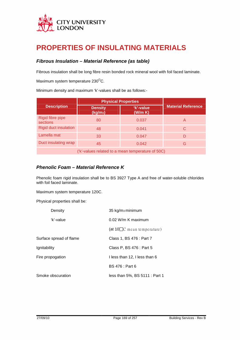
27/09/10 Page 169 of 257 Building Services - Rev B
PROPERTIES OF INSULATING MATERIALS Fibrous Insulation – Material Reference (as table) Fibrous insulation shall be long fibre resin bonded rock mineral wool with foil faced laminate. Maximum system temperature 230OC. Minimum density and maximum ‘k’-values shall be as follows:-
Description Physical Properties
Material Reference Density (kg/m3)
‘k’-value (W/m K)
Rigid fibre pipe sections 80 0.037 A
Rigid duct insulation 48 0.041 C Lamella mat 33 0.047 D Duct insulating wrap 45 0.042 G
(‘k’-values related to a mean temperature of 50C) Phenolic Foam – Material Reference K Phenolic foam rigid insulation shall be to BS 3927 Type A and free of water-soluble chlorides with foil faced laminate. Maximum system temperature 120C. Physical properties shall be:
Density 35 kg/m3 minimum ‘k’-value 0.02 W/m K maximum
(at 10C me a n te mpe ra ture )
Surface spread of flame Class 1, BS 476 : Part 7 Ignitability Class P, BS 476 : Part 5 Fire propogation I less than 12, I less than 6
BS 476 : Part 6 Smoke obscuration less than 5%, BS 5111 : Part 1
27/09/10 Page 170 of 257 Building Services - Rev B
Flexible Closed Cell Insulation – Material Reference N The insulating material shall be expanded nitrile rubber elastomeric closed cell with a smooth external vapour barrier surface and shall achieve Class ‘O’ fire rating to the Building Regulations. Maximum system temperature 116C. Physical properties shall be: Density 90 kg/m3 minimum ‘k’-value 0.040 W/m K at 20C
0.038 W/m K at 0C
Surface spread of flame Class 1, BS 476 : Part 7 Ignitability Class P, BS 476 : Part 5 Fire propogation I less than 12, I less than 6 BS 476 : Part 6 Water vapour permeance 0.01 g/s MN Water absorption 2.5% (28 days) by volume Ozone resistance ‘no cracking’ (ASTM-D-1171) Resistance to oils & greases ‘high’
27/09/10 Page 171 of 257 Building Services - Rev B
VAPOUR BARRIERS Vapour barriers shall be separately applied (except where part of a composite insulating system) and be maintained continuous and sealed to be resistant to the passage of water vapour. The permeance shall not exceed 0.05 g/s MN for cold water and 0.015 g/s MN for chilled water systems. Material Reference Vb1 Reinforced aluminium foil having a minimum thickness of 0.008 mm factory bonded to the insulation material with all joints sealed using matching self-adhesive foil tape with at least 25 mm overlap to maintain the vapour seal.

27/09/10 Page 172 of 257 Building Services - Rev B
CLADDING MATERIALS Aluminium Cladding – Material Reference C1 Embossed aluminium sheet - less than 150 mm diameter over insulation 0.7 mm thickness - over 150 mm but less than 450 mm 0.9 mm - over 450 mm and flat surfaces 1.0 mm - joints lapped 40 mm minimum - fixings spaced not more than 150 mm apart ‘Aluzink’ Cladding - Material Reference C2 Embossed aluminised steel sheet - less than 150 mm diameter over insulation 0.5 mm thickness - over 150 mm but less than 450 mm 0.8 mm - over 450 mm and flat surfaces 1.0 mm - joints lapped 40 mm minimum - fixings spaced not more than 150 mm apart ‘Plastisol’ Cladding – Material Reference C3 Vinyl-coated zintec steel sheet, leather grain finish, colour to be agreed - less than 150 mm diameter over insulation 0.5 mm thickness - over 150 mm but less than 450 mm 0.7 mm - over 450 mm and flat surfaces 0.9 mm - joints lapped 40 mm minimum - fixings spaced not more than 150 mm apart

27/09/10 Page 173 of 257 Building Services - Rev B
Pib Cladding - Material Reference C4 Polyisobutylene sheet, factory applied where practicable, black colour, 0.8 mm thickness with 50 mm to 75 mm overlaps for bonding to itself with a suitable solvent-type adhesive.
27/09/10 Page 174 of 257 Building Services - Rev B
TRACE HEATING General The construction of heating tapes, and the design of system employing them shall generally be in accordance with BS 6351 Parts 1 and 2, subject to the limitations stated in this document. Power Supply The tapes shall be suitable for operation at 240 volts 50 Hz. The supply shall be derived from a power source through a suitable rated residual current device. The residual current value shall not exceed 30mA. The power supply shall be terminated in a junction box close to the point where the heating tape installation starts. If located outdoors the junction box shall be protected to IP65 standard. The number of tapes connected to each electrical circuit shall be as shown on the drawings or determined in conjunction with the Engineer. Heating tapes on the same pipe or vessel system only shall be considered for connection to a common electrical circuit. Construction The heating tapes shall be of the self-limiting type, which can be cut to length on site and suitably sealed to prevent ingress of moisture. Sealing methods shall be approved in writing by the tape manufacturer, a copy shall be handed to the Engineer. The insulating materials used shall be suitable for temperatures at least 20C in excess of the highest temperature normally achievable by the tape in operation. The insulating sheath covering the part of the tape shall be covered with metallic braiding for its whole length, the braiding being connected to earth at the supply point. The braiding shall be covered with suitable insulation material in the form of an overall sheath. The insulation materials used in the construction of the tape shall not be affected by:- Liquids or vapours contained within the pipe or vessel being traced Or Liquids and vapours in the atmosphere surrounding the pipe or vessel concerned.

27/09/10 Page 175 of 257 Building Services - Rev B
Installation The installation of heating tapes shall be carried out in accordance with the manufacturer's recommendations. Approval of the installation by the manufacturer's representative shall be required prior to the installation of any insulation. The Installer shall be responsible for all remedial works resulting from failure to carry out this procedure. Suppliers Tapes shall be manufactured by Isopad or Raychem. Alternatives may be submitted for the Engineer's comments.
27/09/10 Page 176 of 257 Building Services - Rev B
INSTALLATION (PIPES AND DUCTS) General All pipes and ducts shall be individually insulated. The outer surface of all insulated work shall present a smooth firm and unbroken appearance. Overlaps shall be neat and even and parallel to circumferential and longitudinal joints. Damaged or punctured foil faced laminate or closed–cell flexible foam insulation will not be accepted at Handover regardless of the cause of damage. All joints shall be closely butted together. Where necessary full insulation thickness shall be achieved by multi-layer application with staggered joints. Where thermostats, sensing devices, detectors, test points, etc and name plates, plant instructions, access doors, damper spindles, quadrants, etc are provided the insulation shall be cut away and the edges neatly finished and sealed. Outside buildings in open air and in external trenches the outer covering to the insulation shall be continuous and fully weatherproof. At entry to buildings from outside the weatherproof outer covering shall be dressed up to a purpose-made flanged metal sleeve or cravat arrangement. Details to be submitted to the Engineer for approval. Duct Insulation The installation of foil faced mineral wool and phenolic foam insulation on ductwork shall comprise of securing the insulation with adhesive in accordance with the manufacturer’s recommendations. Pins/hangers onto which insulation shall be impaled and fixed with spring clip washers shall be spaced at maximum 300 mm centres on the underside of horizontal ducts and on vertical sides. Rigid slabs for rectangular ducts shall be applied so that top and bottom members overlap side slabs. Straight butt joints shall be sealed using 50 mm wide matching self-adhesive foil tape. Corner butt joints and insulation hanger penetrations shall be sealed using foil tape of width 50 mm + thickness of insulation. Joints and hanger penetrations for foil faced flexible ductwrap and lamella mineral wool insulation on ductwork shall be sealed with 100 mm wide matching self-adhesive foil tape. Mineral wool and phenolic foam insulation on circular and flat oval ducts shall be further retained by light gauge aluminium bands evenly spaced at maximum 450 mm centres applied to ensure the insulation is not compressed. Wire shall not be used to secure insulation. Closed-cell flexible foam insulation shall be applied in accordance with the manufacturers instructions and be continuously sealed with adhesive at all joints. Sheet material shall be directly attached to duct surfaces. Duct Supports Ducts conveying cold air or where susceptible to the formation of condensation shall be fitted with non-combustible compression resistant insulant at each support point before application
27/09/10 Page 177 of 257 Building Services - Rev B
of duct insulation. The insert shall match the insulation thickness. Vapour barriers where required shall be carried across duct inserts. Drop rod fixing to bottom supports to suspended ductwork shall leave sufficient clearance for application of insulation and vapour barrier to duct sides. Pipe Insulation Joints and overlaps on foil faced preformed rigid mineral wool and phenolic foam pipe sections shall be sealed using 50 mm wide matching selfadhesive foil tape. Preformed rigid mineral wool and phenolic foam pipe sections shall be retained in position by light gauge aluminium bands evenly spaced at maximum 300 mm centres applied to ensure the insulation is not compressed. Wire shall not be used to secure insulation. Closed-cell flexible foam insulation shall be applied in accordance with the manufacturers instructions and be continuously sealed with adhesive at all joints. Sheet material shall be directly attached to pipe surfaces. Fittings shall be insulated to the same standard as adjacent pipework with moulded sections, but can alternatively be mitred with a minimum of three changes of direction (more on large pipework) provided a high standard of finish is achieved. The insulation shall, as necessary, allow for the diameter and shape of any pipe compression nuts and shall be fixed as for straight runs. Pipe Supports Pipes conveying cold fluids, including external cold water pipes, shall be fitted with non-combustible compression resistant insulant cylindrical form inserts of 70 mm length minimum at each support point before application of pipe insulation. Where pipe movement is facilitated by rollers or similar devices, the load bearing insulation shall extend beyond the limits of pipe movement. The insert shall match the insulation thickness and pipe outside diameter and be suitable for the operating temperature. Vapour barriers where required shall be carried across pipe inserts. Drop rod fixing to supports on suspended pipework shall leave sufficient clearance for application of insulation and vapour barrier. Protection Of Insulation For Maintenance Access Where access is necessary for maintenance, or any other purpose, and entails standing on insulation sections minimum length 1 metre of 1.2 mm thick galvanised, aluminised or vinyl-coated steel sheet shall be provided and suitably and continuously supported with non-combustible compression resistant insultant inserts designed to avoid damage to the insulation.

27/09/10 Page 178 of 257 Building Services - Rev B
Where pipework or ductwork is installed adjacent to an access requiring regular maintenance sections of insulation likely to be rubbed (hence damaged) shall be finished as for plant rooms. Static Electricity In flameproof areas each separate run of metallic cladding on pipework or ductwork shall be bonded to earth in at least one place. The means of bonding may be to the earthed pipe or a recognised earth bonding point. Metallic cladding on vessels and equipment shall also be bonded to earth. The means of bonding may be to the earthed vessel and equipment or a recognised earth bonding point. The Electrical engineer shall be advised of all new installations. They will check the continuity of bonding and record the initial results. Hot Surfaces Valves, flanges and strainers shall be fitted with purpose-made removable silicone coated glass cloth covers having 50 mm thickness mineral fibre insert and ‘velcro’ or laced fasteners, or formed removable sheet metal insulation boxes with quick-release toggles. Valves, flanges and strainers on steam and condense systems shall first be covered with 25 mm thick foil faced flexible insulating wrap. Stuffing boxes and glands shall not be covered. Other fittings shall be insulated as for pipework. All insulation shall allow access to flange bolts and nuts. Steam condense pump bodies shall be encased in purpose-made removable insulated covers or metal boxes. Cold Surfaces For temperatures below ambient dew point a vapour barrier shall be provided and maintained throughout the whole system. Valves, flanges, strainers, fittings and pump bodies shall be insulated, provided with a vapour barrier and cased. Casings shall be purpose-made removable silicone coated glass cloth covers having 50 mm thickness mineral fibre insert and ‘velcro’ or laced fasteners, or formed removable sheet metal insulation boxes with quick-release toggles. Valves, flanges, strainers, fittings and pumps shall first be covered with 50 mm thick foil faced flexible insulating wrap sealed with aluminium foil tape. The vapour seal shall be lapped onto the bare pipe adjacent to flanged valves and fittings such that the fitting and flange nuts and bolts can be removed without disturbing the vapour seal. Stuffing boxes and glands shall not be covered. Thermal Expansion And Contraction Provisions for thermal movement shall be made in pipework insulation at maximum intervals of 5 metres. Expansion joints shall comprise of a 12 mm gap packed with flexible insulant and covered with oversize pre-formed insulation affixed to one side of the joint only. The vapour seal shall be designed to accommodate movement at this point.

27/09/10 Page 179 of 257 Building Services - Rev B
Compression joints shall be arranged immediately below insulation support rings on vertical pipes. Pipe expansion devices shall operate without interference by insulation which shall be carried over such devices on close-clearance sheet metal sleeves secured at one end only. Ductwork Access Doors Access doors and panels shall be of the insulation, vapour barrier standard and external finish as the ductwork where located. Proprietary devices meeting these requirements and providing water resistant and air sealed construction will be considered for acceptance.

27/09/10 Page 180 of 257 Building Services - Rev B
CISTERN, TANK, CYLINDER AND CALORIFIER INSULATION Cisterns And Tanks The top, bottom (except support positions) and all sides including external flanged joints of water storage cisterns and tanks and feed & expansion tanks shall be thermally insulated and vapour sealed. Inspection covers shall be individually insulated and vapour sealed. The installation of foil faced mineral wool rigid slab, phenolic foam rigid insulation or closed-cell flexible foam insulation on rectangular tanks shall comprise of securing the insulation with adhesive in accordance with the manufacturer’s recommendations. Pins/hangers onto which mineral wool or phenolic foam insulation shall be impaled and fixed with spring clip washers shall be spaced at maximum 300 mm centres on the underside and vertical sides of tanks. Insulation shall be arranged such that top and bottom elements overlap side slabs. Straight butt joints shall be sealed using 50 mm wide matching selfadhesive foil tape. Corner butt joints and insulation hanger penetrations shall be sealed using foil tape of width 50 mm + thickness of insulation. Circular tanks shall be insulated using lamella mineral wool, phenolic foam or closed-cell flexible foam insulation. Joints in mineral wool and phenolic foam insulation on circular tanks shall be sealed with 100 mm wide matching selfadhesive foil tape and further retained by filament tape 38 mm wide at maximum 300 mm centres applied to ensure the insulation is not compressed. Wire shall not be used to secure insulation. Closed-cell flexible foam insulation shall be applied in accordance with the manufacturers instructions and be continuously sealed with adhesive at all joints. Sheet material shall be directly attached to the tank surfaces.
27/09/10 Page 181 of 257 Building Services - Rev B
Vessels And Calorifiers (General Requirements) Tube chests, manways and the like shall be fitted with purpose-made removable insulated cases or metal boxes as described for Hot Surfaces and Cold Surfaces specified above, allowing for the making and disconnecting of joints. External flanged joints on vessels and calorifiers shall be thermally insulated and vapour sealed. Vessels And Calorifiers (Hot) Horizontal and vertical cylindrical hot water storage vessels, heating calorifiers and heat exchangers shall be insulated using lamella mineral wool with foil faced laminate on the outer side. Materials shall be fully in contact with the surface to be covered by setting in a suitable approved adhesive. Additionally intermediate support rings or cleats shall be provided as necessary and each layer banded on at no greater than 450 mm centres. Wire shall not be used to secure insulation. Joints shall be sealed using 100 mm wide self-adhesive reinforced aluminium foil tape. Hot water storage cylinders up to 1200 mm diameter may be covered with purpose-made insulating jackets, designated incombustible when tested in accordance with BS 476 : Part 4 and conforming to BS 5615. Vessels And Calorifiers (Cold) Horizontal and vertical cylindrical cold water storage vessels and heat exchangers shall be insulated using lamella mineral wool or phenolic foam with foil faced laminate on the outer side. Materials shall be fully in contact with the surface to be covered by setting in a suitable approved adhesive. Additionally intermediate support rings or cleats shall be provided as necessary and each layer banded on at no greater than 450 mm centres. Wire shall not be used to secure insulation. Joints shall be vapour sealed using 100 mm wide self-adhesive reinforced aluminium foil tape. Support legs and skirts shall be insulated for a length of four times insulation thickness from the insulated body surface. Feed And Vent Pipes All feed and expansion and safety vent pipes shall be insulated and vapour sealed as specified for the associated system.
27/09/10 Page 182 of 257 Building Services - Rev B
PAINTING Painting (General) Remove rust scale and insulation waste by brushing down thoroughly with a wire brush. Gunmetal rollers or moving parts shall not be painted. On completion of all painting, grease all rollers and moving parts of brackets with graphite grease. Care shall be exercised not to paint bearings and other equally unsuitable items. Painting Ferrous Metal Parts Where installed internally the following, once free from rust and scale, are to be painted with one coat of zinc phosphate primer before erection (a works primer coat is accepted in lieu if touched up where cut or damaged). On completion of the work, but before the lagging is put on, the following shall also be painted one coat of black heat resisting paint. All brackets in plant rooms. All brackets in any type of duct, walkway, void and ceiling void. All brackets in areas that are not to be decorated as part of the Building Contract. (Brackets in decorated areas will be further painted as part of the Building Contract). Where installed internally the following, once free from rust, scale and insulation waste, are to be painted with a primer coat (zinc phosphate on steel and galvanised iron and chromate primer on copper and gunmetal) and two coats of approved quality and colour heat resisting paint. All uninsulated parts of services and plant remaining, where generally the services and plant are insulated and metal clad. All uninsulated services and plant in ducts, walkway ducts, voids and ceiling voids. All uninsulated services and plant in plant room (which includes boiler houses and tank rooms). All uninsulated services and plant in areas that are not to be decorated as part of the Building Contract (bare pipework and all heater units in decorated areas will be painted as part of the Building Contract, but all such work must be complete at the time of painting with the manufacturer's primer coat or varnish in a reasonable condition). Galvanised materials shall be treated with an approved proprietary cold paint-bond fluid prior to priming.

27/09/10 Page 183 of 257 Building Services - Rev B
IDENTIFICATION OF ALL SERVICES General All services irrespective of whether insulated or not shall be provided with colour coded identification bands and labels indicating service, size and direction of flow. The identification bands and labels, on suitable ground colours, shall be applied either by painting or by PVC tapes. Where colour coding is painted on it must be carried out using heat-proof paint. The identification bands and labels shall be fixed at all junctions, at both sides of service appliances, bulkheads, wall penetrations, service duct openings, changes in direction and at intervals of 12 metre maximum plus any other places where identification is considered necessary by the Engineer. Additionally, in buildings to be validated all service outlets shall be labelled with the name of the service and all other identification shall meet the requirements of the Regulatory Body. Pipework Installations All pipework irrespective of whether it is insulated or not shall be provided with colour coded identification bands and labels in accordance with the requirements of BS 1710 and City University colour identification booklet. Where pipework is to be decorated and where it is exposed to view in rooms as part of the building contract, identification shall be applied as considered necessary by the Engineer. Ductwork Installations All ductwork irrespective of whether it is insulated or not shall be provided with colour coded identification labels in accordance with the recommendations in the HVCA Specification DW/144. Safety cabinet exhaust ductwork shall be labelled with yellow self-adhesive tape indicating a Biological Hazard complying with sign A.2.10 of BS 5378 Part 3. Equipment All plant items must be clearly and permanently labelled. Hazard Warning Signs The Installer shall provide and install hazard warning signs on any services below 2.0 metre headroom within designated access or escape routes in plant rooms or access voids. The hazard warning signs shall be either painted yellow and black at 45O
or purpose manufactured tape. The Installer shall seek the Engineers comments as to where and how the signs should be erected. The signs shall be provided at no extra cost to the Contract. The installer shall install warning signs adjacent to each item or machinery which is subject to automatic stop and start

27/09/10 Page 184 of 257 Building Services - Rev B
control. The format and material of construction of the label shall be agreed with the Engineers. The wording shall be:
DANGER
THIS EQUIPMENT MAY START WITHOUT WARNING.
ISOLATE ELECTRICAL SUPPLY BEFORE WORKING ON THE PLANT.
The installer shall install warning signs on all access doors to air handling units and ductwork, etc. The format and material of construction of the label shall be agreed with the Engineers. The wording shall be:
DANGER
DO NOT REMOVE ACCESS PANELS OR OPEN DOORS UNLESS
THE FAN HAS STOPPED.

27/09/10 Page 185 of 257 Building Services - Rev B
THERMAL INSULATION SELECTION SCHEDULES The following references and codings shall apply for thermal insulating materials, vapour barriers and cladding. Insulating Materials Reference A - mineral rock wool rigid preformed pipe sections
C - mineral rock wool rigid duct insulation D - mineral rock wool lamella mat G - mineral wool duct insulating wrap K - phenolic foam rigid insulation N - flexible closed-cell insulation
Vapour Barriers Reference VB1 – aluminium foil fibre reinforced Cladding And Finishes Reference C1 – embossed aluminium sheet
C2 – aluminised steel sheet C3 – Vinyl coated steel sheet C4 – polyisobutylene flexible sheet
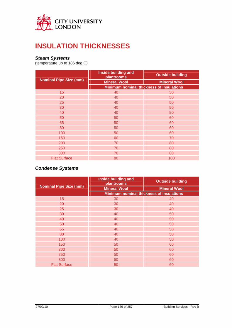
27/09/10 Page 186 of 257 Building Services - Rev B
INSULATION THICKNESSES Steam Systems (temperature up to 186 deg C)
Nominal Pipe Size (mm)
Inside building and plantrooms Outside building
Mineral Wool Mineral Wool Minimum nominal thickness of insulations
15 40 50 20 40 50 25 40 50 30 40 50 40 40 50 50 50 60 65 50 60 80 50 60 100 50 60 150 60 70 200 70 80 250 70 80 300 70 80
Flat Surface 80 100 Condense Systems
Nominal Pipe Size (mm)
Inside building and plantrooms Outside building
Mineral Wool Mineral Wool Minimum nominal thickness of insulations
15 30 40 20 30 40 25 30 40 30 40 50 40 40 50 50 40 50 65 40 50 80 40 50 100 40 50 150 50 60 200 50 60 250 50 60 300 50 60
Flat Surface 50 60
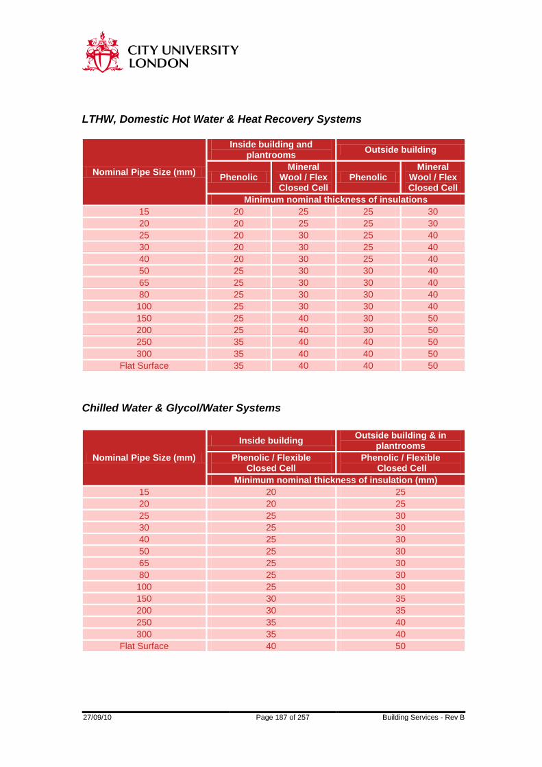
27/09/10 Page 187 of 257 Building Services - Rev B
LTHW, Domestic Hot Water & Heat Recovery Systems
Nominal Pipe Size (mm)
Inside building and plantrooms Outside building
Phenolic Mineral
Wool / Flex Closed Cell
Phenolic Mineral
Wool / Flex Closed Cell
Minimum nominal thickness of insulations 15 20 25 25 30 20 20 25 25 30 25 20 30 25 40 30 20 30 25 40 40 20 30 25 40 50 25 30 30 40 65 25 30 30 40 80 25 30 30 40 100 25 30 30 40 150 25 40 30 50 200 25 40 30 50 250 35 40 40 50 300 35 40 40 50
Flat Surface 35 40 40 50
Chilled Water & Glycol/Water Systems
Nominal Pipe Size (mm)
Inside building Outside building & in plantrooms
Phenolic / Flexible Closed Cell
Phenolic / Flexible Closed Cell
Minimum nominal thickness of insulation (mm) 15 20 25 20 20 25 25 25 30 30 25 30 40 25 30 50 25 30 65 25 30 80 25 30 100 25 30 150 30 35 200 30 35 250 35 40 300 35 40
Flat Surface 40 50
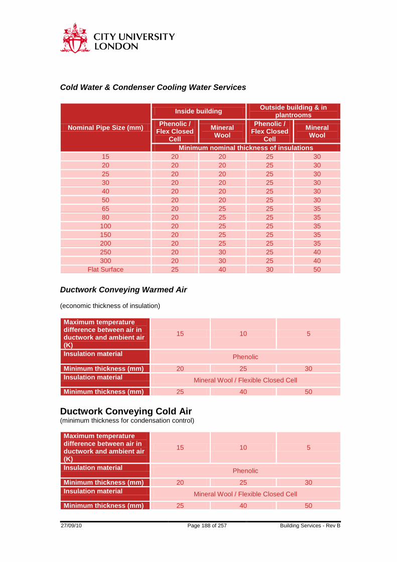
27/09/10 Page 188 of 257 Building Services - Rev B
Cold Water & Condenser Cooling Water Services
Nominal Pipe Size (mm)
Inside building Outside building & in plantrooms
Phenolic / Flex Closed
Cell Mineral Wool
Phenolic / Flex Closed
Cell Mineral Wool
Minimum nominal thickness of insulations 15 20 20 25 30 20 20 20 25 30 25 20 20 25 30 30 20 20 25 30 40 20 20 25 30 50 20 20 25 30 65 20 25 25 35 80 20 25 25 35 100 20 25 25 35 150 20 25 25 35 200 20 25 25 35 250 20 30 25 40 300 20 30 25 40
Flat Surface 25 40 30 50
Ductwork Conveying Warmed Air (economic thickness of insulation) Maximum temperature difference between air in ductwork and ambient air (K)
15 10 5
Insulation material Phenolic
Minimum thickness (mm) 20 25 30 Insulation material Mineral Wool / Flexible Closed Cell
Minimum thickness (mm) 25 40 50 Ductwork Conveying Cold Air (minimum thickness for condensation control) Maximum temperature difference between air in ductwork and ambient air (K)
15 10 5
Insulation material Phenolic
Minimum thickness (mm) 20 25 30 Insulation material Mineral Wool / Flexible Closed Cell
Minimum thickness (mm) 25 40 50
27/09/10 Page 189 of 257 Building Services - Rev B
SECTION 7
AIR HANDLING EQUIPMENT
27/09/10 Page 190 of 257 Building Services - Rev B
AIR HANDLING EQUIPMENT Packaged Air Handling Units All air handling unit sections shall consist of hollow section frames with fully insulated double skin panels. Open pentapost construction shall not be acceptable. The frame shall be fabricated from powder coated extruded aluminium or hot dip galvanised or zintec mild steel and as approved by the Engineer. Units shall be fitted with legs to provide a minimum of 300 mm clear from the bottom of the unit to the floor (exact dimension is dependant on the height required for gravity drainage of the steam condense). The panels shall be at least 25 mm thick of double skin construction, manufactured from 18 SWG (1.219 mm) galvanised/zintec steel sheet. The outer panel shall be coated with Plastisol to a choice of colour. Insulation within the panels shall be mineral wool or other approved material having a density of not less than 80 to 110 kg/m3 and a thermal conductivity not greater than 0.04 W/m OC. The panels shall be reinforced and stiffened where necessary to achieve the required stiffness under pressure. The frame if steel shall be painted using suitable primer and undercoat, followed by a top coat of non toxic gloss paint. The units shall be able to withstand indefinitely an internal positive and negative pressure of not less than 1.2 times peak fan curve static pressure. The units shall be no less airtight than the connected ductwork system and shall be leak tested to DW143. Air handling units shall be suitable for stacking where shown, without additional site provided supports. The lower unit must accept the upper unit without visible distortion. Air handling units must present a clean external appearance and must be of a constant external cross section. The use of external bolts or flanges shall be avoided. It shall not be possible for maintenance personnel to be exposed to risk of cuts and abrasions. The floor of each section shall be designed to carry the concentrated loads resulting from the activities of maintenance personnel. Floor decking shall be used where required to support a loading of 1.5 kN/m2. Access sections shall be provided to give access to and allow removal and maintenance of all components. Access doors shall be provided to give access into fan, filter, cooling coil and humidifier sections and shall be 500 mm wide minimum clear access. Access doors shall be provided with hinges, handles and door locks. Gaskets shall be synthetic rubber, fitted without gaps to provide continuous contact with the door and shall be mechanically fixed. All fastenings shall be resistant to vibration. Double glazed inspection ports, not less than 200 mm diameter, shall be provided in fan and humidifier sections. Bulkhead lights wired out in continuous conduit to weatherproof switches on the outside of the unit casings shall be installed in the fan, humidifier and all access sections. Where units are shown requiring plenum chambers, they shall be constructed to the same standard and finish as the rest of the unit. Units incorporating cooler batteries and/or humidifiers shall have welded stainless steel drain trays, extended as necessary to drain away any water deposited or condensed in adjacent sections. Drain trays shall be insulated and vapour sealed. Drain trays shall be filled with

27/09/10 Page 191 of 257 Building Services - Rev B
water and tested for leaks after installation on site. Other exposed metal surfaces shall be protected by a properly prepared and applied two-coat paint finish or other approved finish to prevent corrosion. Units shall be provided with purpose built sampling points for temperature and pressure between all components. These shall be brass complete with screwed cap and sealing washer. A minimum 12.5 mm clear hole shall be provided to accept probes. The air handling unit supplier shall be provided with mounting points for all automatic controls. These will be supplied free issue and shall be fitted in accordance with the Specialists instructions to avoid on-site drilling of units. Units shall be delivered to site protected with polystyrene foam and hardboard. All coil connections, etc., shall be exposed to avoid removal of packing until the latest practical time. Faces requiring early exposure, eg. ends and bottom, shall be easily removable without disturbing sides and top.

27/09/10 Page 192 of 257 Building Services - Rev B
MIXING SECTIONS Mixing sections shall have opposed blade dampers arranged to provide efficient mixing of the flows. Inlet and outlet dampers shall have rubber seals to limit leakage. Selection of the recirculating damper shall be carried out to ensure accurate air balancing. Perforated plate shall be employed where required to balance resistances. Dampers shall be selected in accordance with CIBSE Applications Manual AM1 Automatic Controls. Dampers shall be of rigid construction made of galvanised steel or aluminium. Blades shall be of aerofoil section mounted on robust cadmium plated spindles and bearings shall be of the sealed, maintenance free type.

27/09/10 Page 193 of 257 Building Services - Rev B
AIR FILTERS All filters shall be manufactured by Camfil or equal and approved. Filter assemblies shall operate with not less than the efficiences or values of arrestance specified for individual cells. The entire framework shall be securely fixed in position with all edges and joints effectively sealed to prevent air leakage. Filter media, casings and frames including all materials of construction, adhesives, coatings and wetting agents shall permanently retain selfextinquishing properties, be of the non-combustible type and be UL/FM approved to have smoke development and flame spread not to exceed 25. Air filter casings, filter medium and sealing gaskets shall be of materials campatible with the temperature, humidity or corrosive conditions. Casings shall not warp, splinter or corrode. Filters arranged for side withdrawal shall not be used, unless otherwise indicated. Each filter assembly shall be fitted with a 100 mm diameter Dwyer magnehelic differential pressure gauge. The gauge shall be provided with a label showing the maximum working resistance of the filter. A set of spare filters shall be provided to completely replace each filter assembly and shall not be fitted without the prior approval of the Engineer. Panel Filters F7 Glass media bag filter for both pre and secondary filtration. Typical sizes are 592 x 592 x 635mm, 12 pockets.
27/09/10 Page 194 of 257 Building Services - Rev B
High Efficiency Particulate Air (Hepa) Filters HEPA filters shall consist of pleated glass paper or other approved medium sealed within a rigidly constructed case. Unless indicated otherwise, a 6 mm thick gasket shall be fitted to the downstream face of the filter. The gasket shall be of one-piece moulded construction. Before any filter is fitted the gasket shall be suitably lubricated to prevent subsequent adhesion to its mating flange. Where adequate access is provided holding-down bolts are acceptable. For HEPA filters in side-withdrawal frames, retention shall be by over-centre cam operation with pressure adjustment. Each filter assembly shall be fitted with suitable sample and test points for onsite testing of the filter and seals. HEPA filters shall be selected strictly in accordance with the manufacturers recommendations of air velocity and pressure differentials. HEPA filters shall be tested as part of the final commissioning by a competent specialist. The test shall be conducted using the DOP method under design air flow conditions and witnessed by the Engineer. On completion of satisfactory testing a test certificate shall be issued.

27/09/10 Page 195 of 257 Building Services - Rev B
HOT WATER AIR HEATER BATTERIES Heater batteries greater than 1.8 m in width shall be split and staggered to ensure ease of removal. Batteries shall be installed in such a manner as to provide easy side withdrawal. Each section of battery shall be supported so that their weight is not transmitted to other sections or pipework and so that removal can be achieved without disturbing adjacent sections and services. Isolating valves shall be provided on the inlet and outlet connections, together with flanged or union joints as appropriate, arranged to facilitate removal of the battery. Heater batteries shall have casings manufactured from sheet steel galvanised after manufacture not less than 1.2 mm thick with flanges at each end drilled to match connecting ductwork or other associated equipment. Anti-frost heaters fitted in fresh air intakes shall have plain copper tubing (or with the approval of the Engineer, tubing with widely spaced copper fins at not less than 6 mm pitch) and shall offer minimum resistance to air flow consistent with achieving the required heat transfer. Preheater and reheater batteries shall comprise copper tubes with aluminium or copper fins at a spacing not exceeding 300 per metre, fitted into copper or bronze headers. The secondary extended heating surface of either aluminium or copper shall extend for the full width of the battery and shall make firm and continuous contact with the primary tubes. Provision shall be made for expansion of the tubes within the casing. Heater batteries shall have horizontal primary tubes, vertical fins and vertical headers. Copper tubes shall comply with BS 2871 Part 3. Tubes shall be 0.71 mm minimum wall thickness with bends and return bends of 0.91 mm wall thickness. Fins shall be of smooth plain 0.4 mm aluminium or of smooth plain 0.25 mm copper. Flow and return connections and headers shall be arranged to ensure an equal flow of water through all tubes. The battery design shall be arranged for contraflow with the water entering at the air leaving end and leaving at the air entering end. The connections shall be on the same side of the coil, unless indicated otherwise, with flow in at the bottom and return out at the top. Manual air vents and drains shall be provided for each coil. Self-sealing test points shall be provided on the inlet and outlet connections to each battery. Connections up to 50 mm nominal bore and pressures up to 350 kN/m2 (3.5 barg) shall be screwed to BS EN10266:2004 taper or flanged to BS EN1092:2003, rating PN10 minimum. Connections 65 mm nominal bore and above and all sizes where pressures exceed 350 kN/m2 (3.5 barg) shall be flanged to BS EN1092:2003, rating PN10 minimum. Screwed connections shall be made using ground-in bronze spherical seated unions. Wall thickness of all connections shall not be less than the equivalent heavyweight specification to BS 1387. On any system where the static pressure at the heater battery exceeds 750 N/m2 airtight cover boxes shall be provided over the headers and bends. All cover boxes shall be internally insulated with suitable material to the same standard as the connecting pipework. The resistance to air flow of the heater shall not exceed 65 N/m2 and the face velocity shall not exceed 4 m/s. The water pressure drop shall not exceed 25 kN/m2. Before leaving the manufacturer's works, each hot water heater battery shall be tested by using air under water to 1.5 times the working pressure or to 8 bar gauge pressure whichever is greater for 30 minutes. A test certificate shall be issued for each heater battery.

27/09/10 Page 196 of 257 Building Services - Rev B
ELECTRIC AIR HEATER BATTERIES Electric heaters shall have the same casing construction as above. Elements shall be of the sheathed type of grid form. Elements shall be built up from a helical coil of 80/20 Nickel Chrome wire embedded in a refractory material and encased in a seamless heat resisting metal tube. Elements shall be wired to substantial terminals within a terminal box bolted to the casing. A hand test safety cut out and flow switch affording protection to the air heating coil shall be incorporated.
STEAM AIR HEATER BATTERIES Heater batteries greater than 1.8 metre in width shall be split and staggered to ensure ease of removal. Heater batteries greater than 1.0 metre in height shall be split to minimise temperature gradients and the risk of freezing on anti-frost coils. Batteries shall be installed in such a manner as to provide easy side withdrawal. Each section of battery shall be supported so that their weight is not transmitted to other sections or pipework and so that removal can be achieved without disturbing adjacent sections and services. Isolating valves shall be provided on the inlet and outlet connections, together with flanged or union joints as appropriate, arranged to facilitate removal of the battery. Heater batteries shall have casings manufactured from sheet steel galvanised after manufacture not less than 1.2 mm thick with flanges at each end drilled to match connecting ductwork or other associated equipment. Anti-frost heaters fitted in fresh air intakes shall have plain copper tubing (or with prior agreement of the Engineer, tubing with widely spaced copper fins at not less than 6 mm pitch) and shall offer minimum resistance to air flow consistent with achieving the required heat transfer. Preheater and reheater batteries shall comprise copper tubes with aluminium or copper fins at a spacing not exceeding 300 per metre, fitted into copper or bronze headers. The secondary extended heating surface of either aluminium or copper shall extend for the full width of the battery and shall make firm and continuous contact with the primary tubes. Provision shall be made for expansion of the tubes within the casing. Steam heater batteries shall have vertical primary tubes, horizontal fins and horizontal headers. Copper tubes shall comply with BS 2871. Tube wall thicknesses and battery construction shall be suitable for the system operating pressures and temperatures. Tubes shall be 0.91 mm minimum wall thickness. Fins shall be of smooth plain 0.4 mm aluminium or of smooth plain 0.25 mm copper. Inlet and outlet connections and headers shall be arranged to ensure an equal flow of steam through all tubes. The connections shall be on the same side of the coil. Connections up to 50 mm nominal bore and pressures up to 350 kN/m2 (3.5 barg) shall be screwed to BS 10266:2004 taper or flanged to BS 1092:2003, rating PN10 minimum. Connections 65 mm nominal bore and above and all sizes where pressures exceed 350 kN/m2 (3.5 barg) shall be flanged to BS EN1092:2003, rating PN10 minimum. Screwed connections shall be made using ground-in bronze spherical seated unions. Wall thickness of all connections shall not be less than the equivalent heavyweight specification to BS 1387.

27/09/10 Page 197 of 257 Building Services - Rev B
On any system where the static pressure at the heater battery exceed 750 N/m2 airtight cover boxes shall be provided over the headers and bends. All cover boxes shall be internally insulated with suitable material to the same standard as the connecting pipework. The resistance to air flow of the heater shall not exceed 65 N/m2 and the face velocity shall not exceed 4 m/s. Before leaving the manufacturer's works, each steam heater battery shall be hot soaked for 1 hour followed by live steam purge for 30 minutes at a minimum pressure of 140 mbar gauge and then tested for leaks by using air under water 1.5 times the working pressure or to 8 bar gauge pressure whichever is greater for 30 minutes. A test certificate shall be issued for each heater battery. Steam-fed heater batteries and pipework connections shall be configered so as to maintain heat exchanger and interconnecting steam and condense pipework free of condensate at all loads. A steam trap set shall be provided for each battery or battery section.

27/09/10 Page 198 of 257 Building Services - Rev B
CHILLED WATER AIR COOLER BATTERIES Cooling coils greater than 1.8 m in width shall be split to ensure ease of removal. Coils shall be installed in such a manner as to provide easy side withdrawal. Each section of battery shall be supported so that their weight is not transmitted to other sections or pipework and so that removal can be achieved without disturbing adjacent sections and services. Cooling coils shall be 8 rows maximum depth. Isolating valves shall be provided on the inlet and outlet connections, together with flanged or union joints as appropriate, arranged to facilitate removal of the battery. Cooling coils shall have casings manufactured from sheet steel galvanised after manufacture not less than 1.2 mm thick with flanges at each end drilled to match connecting ductwork or other associated equipment. Cooling coils shall comprise copper tubes with copper fins at a spacing not exceeding 300 per metre, fitted into copper or bronze headers, and shall be electro-tinned after assembly to BS 1872 in blocks of no greater than 3 rows deep. The secondary extended heating surface of copper shall extend for the full width of the battery and shall make firm and continuous contact with the primary tubes. Provision shall be made for expansion of the tubes within the casing. Cooling coils shall have horizontal primary tubes, vertical fins and vertical headers. Copper tubes shall comply with BS EN1057:2006. Tubes shall be 0.71 mm minimum wall thickness with bends and return bends of 0.91 mm wall thickness. Fins shall be of smooth plain 0.25 mm copper. Flow and return connections and headers shall be arranged to ensure an equal flow of water through all tubes. The battery design shall be arranged for contraflow with the water entering at the air leaving end and leaving at the air entering end. The connections shall be on the same side of the coil, unless indicated otherwise, with flow in at the bottom and return out at the top. Manual air vents and drains shall be provided for each coil. Self-sealing test points shall be provided on the inlet and outlet connections to each battery. The bottom of all casings shall be made in the form of a watertight drip tray, complete with drain connection. The drain outlet shall be extended to the side of the casing. The drip tray shall be fabricated from stainless steel of fully welded construction. The whole assembly shall be treated to prevent condensation occurring under operating conditions. A separate drip tray shall be provided for each 1.8 metre of coil width with suitable arrangements for sealing between trays. It shall be possible to spray the drain tray, headers and return bends with sterilising fluid. Intermediate drain trays shall be provided where the battery height exceeds 950 mm. Drain tubes from each coil section shall be piped to the drip tray in the base of the unit. Flow and return connections and headers shall be arranged to ensure an equal flow of water through all tubes. The battery design shall be arranged for contraflow with the water entering at the air leaving end and leaving at the air entering end. The connections shall be on the same side of the coil, unless indicated otherwise, with flow in at the bottom and return out at the top. Manual air vents and drains shall be provided for each coil. Self-sealing test points shall be provided on the inlet and outlet connections to each battery. Connections up to 50 mm nominal bore and pressures up to 350 kN/m2 (3.5 barg) shall be screwed to BS EN10266:2004 taper or flanged to BS EN1092:2003, rating PN10 minimum. Connections 65 mm nominal bore and above and all sizes where pressures exceed 350 kN/m2 (3.5 barg) shall be flanged to BS EN1092:2003, rating PN10 minimum. Screwed

27/09/10 Page 199 of 257 Building Services - Rev B
connections shall be made using ground-in bronze spherical seated unions. Wall thickness of all connections shall not be less than the equivalent heavyweight specification to BS EN10255:2004. On any system where the static pressure at the heater battery exceeds 750 N/m2 airtight cover boxes shall be provided over the headers and bends. All cover boxes shall be internally insulated with suitable material to the same standard as the connecting pipework. Resistance to airflow shall not exceed 125 N/m2 under wet coil conditions, resistance to hydraulic fluid shall not exceed 35 kN/m2 and the face velocity shall not exceed 2.25 m/s and point velocity not to exceed 3.0 m/s. Before leaving the manufacturer's works, each cooling coil shall be tested by using air under water to 1.5 times the working pressure or to 8 bar gauge pressure whichever is greater for 30 minutes. A test certificate shall be issued for each cooling coil.

27/09/10 Page 200 of 257 Building Services - Rev B
DIRECT-EXPANSION REFRIGERANT AIR COOLER BATTERIES Cooling coils greater than 1.8 m in width shall be split to ensure ease of removal. Coils shall be installed in such a manner as to provide easy side withdrawal. Each section of battery shall be supported so that their weight is not transmitted to other sections or pipework and so that removal can be achieved without disturbing adjacent sections and services. Cooling coils shall be 8 rows maximum depth. Cooler batteries shall have casings manufactured from sheet steel galvanised after manufacture not less than 1.2 mm thick with flanges at each end drilled to match connecting ductwork or other associated equipment. Cooling coils shall comprise copper tubes with copper fins at a spacing not exceeding 300 per metre, fitted into copper or bronze headers, and shall be electro-tinned after assembly to BS 1872 in blocks of no greater than 3 rows deep. The secondary extended heating surface of copper shall extend for the full width of the battery and shall make firm and continuous contact with the primary tubes. Provision shall be made for expansion of the tubes within the casing. Cooling coils shall have horizontal primary tubes, vertical fins and vertical headers. Tube wall thicknesses and battery construction shall be suitable for the system operating pressures and particular refrigerant. The bottom of all casings shall be made in the form of a watertight drip tray, complete with drain connection. The drain outlet shall be extended to the side of the casing. The drip tray shall be fabricated from stainless steel of fully welded construction. The whole assembly shall be treated to prevent condensation occurring under operating conditions. A separate drip tray shall be provided for each 1.8 metre of coil width with suitable arrangements for sealing between trays. It shall be possible to spray the drain tray, headers and return bends with sterilising fluid. Intermediate drain trays shall be provided where the battery height exceeds 950 mm. Drain tubes from each coil section shall be piped to the drip tray in the base of the unit. Coolers shall be provided with inlet liquid distributors and return suction headers arranged to ensure even distribution of refrigerant to all circuits and to return oil to the compressor. The tubes shall be staggered in the direction of air flow. Liquid distributors, return suction headers and return bends shall be located out of the airstream. All circuits shall have an even number of tubes to ensure that liquid and suction connections are on the same side. Coolers served by more than one DX refrigeration system shall have separate fully interlaced circuits. On any system where the static pressure at the cooler exceeds 750 N/m2 airtight cover boxes shall be provided over the headers and bends, and the provision shall be made for draining the cover boxes. All cover boxes shall be insulated and vapour-sealed with suitable materials to the same standard as the connecting pipework. Resistance to airflow shall not exceed 125 N/m2 under wet coil conditions, resistance to hydraulic fluid shall not exceed 35 kN/m2 and the face velocity shall not exceed 2.25 m/s and point velocity not to exceed 3.0 m/s.

27/09/10 Page 201 of 257 Building Services - Rev B
Before leaving the manufacturer's works, each DX refrigerant cooler battery shall be tested for leaks by using air under water to 19 bar gauge for 30 minutes. On satisfactory completion of all manufacturer's works tests, batteries shall be dehydrated, charged with an inert gas and sealed. A test certificate shall be issued for each DX coil.

27/09/10 Page 202 of 257 Building Services - Rev B
HUMIDIFIERS The humidifier section shall provide at least 1.5 m long unobstructed absorption space after the steam lance. The base of the humidifier section shall be stainless steel and shall slope to a drain point. For details of direct steam injection humidifiers see section 2 - ‘Valves’.
27/09/10 Page 203 of 257 Building Services - Rev B
FAN SECTIONS The fan section shall be constructed of a rigid metal framework, clad with galvanised sheet steel, stiffened and strengthened as necessary to prevent drumming and distortion. Access panels and doors shall be provided where necessary to allow access and maintenance. Replacement of bearings and removal of the fan impellor shall be easily accomplished. Fans and motors shall be mounted internally on a common frame with antivibration mountings to limit vibration. The section shall not be separately mounted. Where practicable a lifting beam shall be mounted internally across the width of the unit for replacing the fan motor(s). The beam shall have an extendable end incorporating a trolley for lifting motors outside the fan casing. The Safe Working Load (SWL) shall be clearly marked on the beam. The beam shall be tested to 50% above the SWL. A Load Test Cetificate and drawing shall be provided.
27/09/10 Page 204 of 257 Building Services - Rev B
CENTRIFUGAL FANS (STEEL) Fans shall be 'type' tested in accordance with BS 848 : Part 1 and Part 2 and be selected to deliver the required air volume flow rate and meet the noise level indicated. Fan curves shall be submitted to indicate performance under all likely operating conditions. Values of resistance of air flow of items of equipment, ductwork and/or the total distribution system, are indicated for tender purposes only. The total system resistance shall be verified by the Contractor, to ensure that fans provided are capable of delivering the required air volume when operating against the actual total system resistance. The Contractor shall compensate for the manufacturers' certified resistance of all equipment being supplied and any other variation to the total system resistance caused by changes to fittings, ductwork layouts or ductwork sizes. Fans shall be constructed to proven design standards and shall be capable of withstanding the pressures and stresses developed during continuous operation at the selected duty, during starting, during stopping and during speed and duty changes. Additionally, belt driven fans shall be capable of running continuously at 10% in excess of the selected duty speed and shall have a minimum of two belts. Fans shall be installed using bolts, nuts and washers with all nuts properly locked and secured. All 'as cast' bearing surfaces for bolt heads and washers shall be machine counterfaced. Holding-down bolts for fans and motors shall be provided with means to prevent the bolts turning when the nuts are tightened. Fans, motors and drive systems shall be adequately sized to be able to achieve an increase of 10% over the absorbed power with filters dirty. Motors shall be Brook Hanson Argus 55 , totally enclosed fan cooled, energy efficient pattern to IP55. Motors shall be suitable for 415 v, 3 ph, 50 Hz electrical supply, 960 or 1440 rpm. Motors over 5 kw shall have thermistor protection to prevent overheating. Motors shall be wired to externally mounted Craig and Dericott IP65 weatherproof isolators in armoured flexible conduit. Where appropriate the motor and drive shall be suitable for mounting outside the building with a weatherproof cover, readily removable for inspection and maintenance. Fans for variable air volume units shall be selected with maximum efficiency at maximum system design flow rate. If the fan selected does not fall within the manufacturer's recommended range at minimum fan speed and resulting system resistance, then the nearest fan size to satisfy this requirement shall be chosen. Where variable speed drives are employed, toothed belt drives shall be provided. Where permanently mounted standby motors are specified, the belt guard shall cover the drive pulley of the standby motor such that all that is required to utilise the standby motor is to fit the vee belts and activate the appropriate control. Fan duties shall be selected for operation with dirty filters. The fans shall not be selected on a flat head part of the curve and the static head at no flow (closed damper) shall be at least 20% greater than that at design condition. No part of the fan curve shall have a negative gradient within the operating range. Fan casings shall be constructed of mild steel sheet or plate with angle stiffeners and base angles to ensure freedom from drumming, and shall be constructed so that impellers may be easily withdrawn after installation. Where necessary, an access door shall be provided in the casing for inspection of the impeller.
27/09/10 Page 205 of 257 Building Services - Rev B
Fans not in air handling units shall have flanged outlet connections and spigoted inlet connections unless indicated otherwise. For negative pressure in excess of 500 Pa, the inlet shall be flanged. A plugged drain shall be fitted at the lowest point of the casing. Casings shall have access panels incorporating air seals to facilitate inspection and cleaning of the impellor. Impellers for higher pressures and consumimg more than 7.5 kW at the fan shaft shall be supplied as backward curved non-overloading aerofoil type, selected for operation at a fan total efficiency of not less than 75%. Forward curved impellers shall only be used for duct pressure class A (low pressure) systems. Impellers shall be of mild steel of riveted or welded construction, with hubs of robust design and shall be capable of running continuously at 20% in excess of the normal speed. The impeller and shaft shall be statically and dynamically balanced to BS 5265 at working speed, and tested for overspeed before leaving the manufacturer's works. The assembly shall be designed so that fan rotational speeds, at the duty point, are at least 35% below the first critical speed. Shaft bearings shall be rigidly mounted on a pedestal either side of the fan and shall be super silent oil lubricated sleeve bearings, or ball bearing Plummer blocks to ensure smooth running throughout the working life of the fan. Bearings shall be selected for a minimum design life of 20,000 hours. Where required, extended lubrication facilities shall be provided. Belt driven centrifugal fans and drive motors shall be located on a common base. Belt drives shall comply with BS 3790 and shall be of rubber and fibre 'vee' section, unless indicated otherwise, with a sufficient number to handle the maximum rating of the fan, plus one additional belt. Not less than two belts per drive shall be used and all multibelt drives shall use matched belts. Drive belts, pulleys and bushes to be by J H Fenner or equal and approved. Provision shall be made to permit drive alignment and adjustment of belt tension. For fans with shaft power up to 5 kW, pivoted mounting plates and jacking bolts may be used. For fans with shaft power above 5 kW, slide rails and jacking bolts shall be provided. Where duplicate motors are provided and fixed, the spare motor shall be complete with an adjusting device to allow belt tensioning and shall be in all respects ready for operation. The centre-to-centre dimensions between the common driven pulley and the duplicate driving pulleys shall be the same. Belt-driven fans shall be fitted with pulleys suitable for the belt drive used. Pulleys may use split taper bushings of an approved type for drive up to 30 kW. Alternatively, and in any case above 30 kW output, pulleys shall be secured to the fan or motor shafts by keys fitted into machined keyways. Pulleys shall be keyed to the shaft in the overhung position. Keys shall be easily accessible for withdrawal or tightening and shall not protrude beyond the end of the shaft. Keys without gib heads shall be drilled and tapped to accept an extractor bolt. Pulleys shall be correctly aligned. Guards shall comply with BS 5304 and be provided to all open fan intakes and exhausts, all forms of open power transmission systems including belt drives, drive shafts and drive couplings.

27/09/10 Page 206 of 257 Building Services - Rev B
Fixed guards shall be installed to prevent inadvertent contact with dangerous parts of machinery. Construction and installation shall ensure strength and rigidity. It shall not be possible to remove any guard or access panel without the aid of a tool. Fans guards shall be purpose-made by the fan manufacturer or meet with the fan manufacturer's approval, and be constructed from galvanised or plastic coated steel wire. Belt drive guards shall be of galvanised woven steel wire of not less than 2.5 mm diameter attached to a rigid galvanised steel rod or angle framework. The mesh size and/or the location of the guard shall prevent finger contact with any enclosed danger point. Alternative construction, and on external drives, may be from galvanised sheet steel not less than 0.8 mm thick stiffened as necessary to ensure a rigid enclosure. Removable access panels shall be provided to permit tachometer readings to be made of motor and driven shafts and belt tension to be tested. The sizes of guards, including the dimensions and locations of access panels, shall provide for the extreme motor position. Anti-vibration mountings shall be in accordance with the Section - 'Noise and Vibration Control'. Flexible connections for fans shall be in accordance with the Section - 'Ductwork (G.S.S.)'. Sound levels shall be in accordance with the Section - 'Noise and Vibration Control' or as indicated otherwise.

27/09/10 Page 207 of 257 Building Services - Rev B
CENTRIFUGAL FANS (PVC) PVC centrifugal fans shall be of the forward curved type with true aerofoil section, solid blades and be welded to a rigid backplate and shroud. Fume extract fan impellors shall be polypropylene. The fan casing for fume extract shall be fabricated from glass reinforced plastic. All other parts which are likely to come into contact with the fumes and gases handled by the fan shall be manufactured or finished with suitably resistant materials. Flexible connectors shall be provided with the fan complete with mating flanges, in accordance with Section - 'Ductwork (P.V.C.)’. Each fan-motor set is to comprise of a centrifugal fan complete with its motor, rigid galvanised welded steel base frame, vee-belt drive and wire protection guard. The base frame is to be fitted with anti-vibration mountings. In all other respects the PVC centrifugal fans shall be in accordance with the previous clause 7.10.
27/09/10 Page 208 of 257 Building Services - Rev B
AXIAL FLOW FANS Axial flow fans shall be capable of giving the specified performance when tested in accordance with BS 848 and evidence supporting claimed fan efficiencies and sound power spectrums shall be provided to the Engineers. Single stage or multi-stage fans shall be provided to suit the duty required. Care must be taken in the selection of each fan, to ensure that fans are not chosen for duties at the end of the frame or motor range. Where possible at least 3 to 4 pitch angle selections should be available above the desired condition for the chosen frame and motor size. Fans, motors and drive systems shall be adequately sized to be able to achieve an increase of 20% over the absorbed power with filters dirty. Unless other wise indicated, casings shall be rigidly constructed of mild steel stiffened and braced as necessary to minimise drumming and vibration. Cast iron or fabricated steel feet shall be provided when necessary for bolting the fan unit to suitable supports. The length of the casing shall be greater than the length of the fan and motor or fans and motors. Inlet and outlet ends of the casing shall terminated in flanged rings for easy connection or removal of the inlet and outlet ducts. Impellers shall be constructed of either steel or aluminium. The blades shall be of aerofoil section and either secured to the hub or formed in one piece with the hub. The impeller and shaft shall be statically and dynamically balanced. The bearings may be ball, roller or ring oiling sleeve type and lubricators shall be extended to the outside of the casing. Unless otherwise indicated, axial flow fans shall be driven by electric motors, either: Direct driven by the motor in the air stream. Belt driven by a motor external to the casing. Direct driven by a motor external to the casing. Where axial flow fans are belt driven and the motor is external to the casing, belt guards shall be manufactured from galvanised sheet steel and provided with air seals to prevent leakage. Where axial flow fans are direct driven by a motor, external to the casing, ie bifurcated type, motors may be placed between the two halves of the casing in the external air, or may be placed within the fan casing provided that effective ventilation is given to the motor. Where hot gases or vapours are being handled, the motor and its bearings shall be suitable for operation at the temperature or conditions they may experience. The requirements for motor shall be as for centrifugal fans.

27/09/10 Page 209 of 257 Building Services - Rev B
PROPELLER FANS Propeller fans shall be capable of giving the specified performance when tested in accordance with BS 848 and evidence supporting claimed fan efficiencies and noise levels shall be provided to the Engineers. Propeller fans may be ring-mounted, diaphragm-mounted, or diaphragmmounted in a casing, as indicated. Where they are mounted in a casing, the casing shall be longer than the length of the fan and motor. Casings shall be of steel, rigidly constructed with flanged ends and shall incorporate an inspection door. Mounting rings and diaphragm plates shall be of mild steel and of rigid construction. Impellers shall be constructed of steel or aluminium. The blades shall be either rigidly secured to the hub or formed in one piece with the hub. Impellers shall be direct driven and guarded where indicated. Tip speed shall be limited to 20 m/s. Shaft bearings shall be ball type, pre-lubricated for life, or fitted with re-lubricating facilities, external to ductwork (where ductwork mounted).

27/09/10 Page 210 of 257 Building Services - Rev B
TOILET EXTRACT FANS Toilet Extract units shall be twin fan duct mounted centrifugal fan type. Casings shall be constructed of sheet steel or aluminium, stiffened or braced where necessary to eliminate drumming and vibration. Fans shall be mounted on a heavy gauge framework and attached to the case by anti-vibration mounts to minimise mechanical noise and vibration. An easily removed cover shall be provided to facilitate servicing of fans and motors. Fans shall be high efficiency, double inlet, double width, centrifugal type with forwarded curved impellers, either direct or belt-driven by electrical motors. Air operated flow switches shall be fitted in each fan outlet to sense failure of airflow and to activate the standby switching and warning signals. Each unit shall be supplied with the necessary control unit to provide duty sharing and automatic changeover in the event of air flow failure. Units shall be pre-wired to a single terminal box fitted to the casing. Auxiliary contact terminal strips shall be provided to give indication to a remote point as specified elsewhere.
27/09/10 Page 211 of 257 Building Services - Rev B
FILTER SPECIFICATION SHEETS

27/09/10 Page 212 of 257 Building Services - Rev B
SECTION 8
NOISE AND VIBRATION CONTROL

27/09/10 Page 213 of 257 Building Services - Rev B
General Requirements The Installer shall employ the services of a specialist manufacturer to provide the acoustic products detailed herein. The specialist manufacturer shall be one of the companies listed elsewhere. It shall be the responsibility of the Installer to ensure that all noise and vibration levels specified for internal and external areas are not exceeded due to the operation of the engineering services installation. Particular consideration shall be given by the Installer to the following, as applicable.
1 Plant noise transmission to the conditioned space via the
distribution ductwork.
2 Plant noise breakout from ductwork distribution systems. 3 Plant airborne noise transmission through the plant room structures.
4 Plant structure borne noise and vibration transmission. 5 Plant noise transmission to exterior positions. 6 Velocity generated noise within the ductwork distribution system. 7 Noise from terminal fittings such as grilles, diffusers etc. 8 Noise and vibration transmission from fan coil units. 9 Acoustic crosstalk between separate areas. 10 Pipe-borne noise. 11 Noise from boilers and flues.
The noise and vibration control equipment is the minimum required to meet the specified noise and vibration levels and has been selected to suit the equipment on which the designs have been based. To ensure that the specified noise and vibration levels are achieved the Installer shall provide, to the Specialist Manufacturer of acoustic products, details of the plant he intends to install. The Installer shall advise the Engineers, in writing, of the details of any level of plant which produces a sound power level greater than 85dBA, or a sound pressure level greater than 75dBA at 1 metre. A fully documented set of the Specialist Manufacturer's calculations shall be provided to the Engineers for comment four weeks prior to ordering plant and noise and vibration control equipment. These calculations shall demonstrate that the selected plant and the selected noise and vibration control equipment enable all specified noise and vibration criteria to be achieved. The Installer shall provide, at no extra cost to the Contract, sufficient noise and vibration control equipment to meet all specified noise and vibration criteria.
27/09/10 Page 214 of 257 Building Services - Rev B
The satisfaction of all specified noise and vibration levels shall be demonstrated by the Installer. Acoustic commissioning tests shall be carried out with all plant and machinery running normally and delivering the design conditions of ventilation, temperature and humidity. The measurement of internal noise levels shall be undertaken in accordance with the procedures set out in Appendix A. In the case of contractual deficiency, and if requested by the Engineer, the Installer shall return at any time during the Contract and take additional readings at no additional cost to the contract in order to demonstrate the satisfaction of all specified noise and vibration criteria.
27/09/10 Page 215 of 257 Building Services - Rev B
INTERNAL NOISE RATINGS Noise levels produced within internal areas due to the operation of the engineering services installation shall be less than or equal to the specified noise ratings. Where a range of noise ratings is specified the lower noise level shall be satisfied, unless otherwise agreed in writing by the Engineer. Where a type of space is included in the building with no equivalent space included in the list of noise ratings, the Installer shall bring this matter to the attention of the Engineer by writing.
All rooms and spaces NR 40 (except where detailed below) Toilets and Corridors NR 45 Plant Rooms NR 60 Conference and Lecture Rooms NR 30 Enclosed Offices NR 35
Noise levels produced at the boundary of the site by the engineering services installation shall not exceed the environmental noise criteria specified by then Local Authority. If a boundary noise criterion has not been set by the Local Authority at tender stage, the boundary noise criterion shall be defined as follows, for design purposes only; "the operation of the engineering services installation shall not cause an increase of more than 1dBA in the existing corrected background noise level at the boundary (as measured in accordance with BS 4142). A 6dB safety margin shall be allowed to account for the cumulative effects of other noise sources associated with the Development".
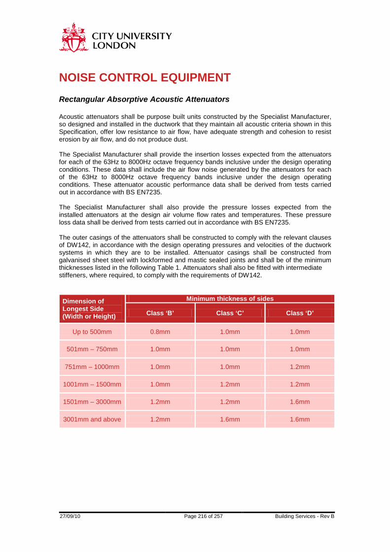
27/09/10 Page 216 of 257 Building Services - Rev B
NOISE CONTROL EQUIPMENT Rectangular Absorptive Acoustic Attenuators Acoustic attenuators shall be purpose built units constructed by the Specialist Manufacturer, so designed and installed in the ductwork that they maintain all acoustic criteria shown in this Specification, offer low resistance to air flow, have adequate strength and cohesion to resist erosion by air flow, and do not produce dust. The Specialist Manufacturer shall provide the insertion losses expected from the attenuators for each of the 63Hz to 8000Hz octave frequency bands inclusive under the design operating conditions. These data shall include the air flow noise generated by the attenuators for each of the 63Hz to 8000Hz octave frequency bands inclusive under the design operating conditions. These attenuator acoustic performance data shall be derived from tests carried out in accordance with BS EN7235. The Specialist Manufacturer shall also provide the pressure losses expected from the installed attenuators at the design air volume flow rates and temperatures. These pressure loss data shall be derived from tests carried out in accordance with BS EN7235. The outer casings of the attenuators shall be constructed to comply with the relevant clauses of DW142, in accordance with the design operating pressures and velocities of the ductwork systems in which they are to be installed. Attenuator casings shall be constructed from galvanised sheet steel with lockformed and mastic sealed joints and shall be of the minimum thicknesses listed in the following Table 1. Attenuators shall also be fitted with intermediate stiffeners, where required, to comply with the requirements of DW142.
Dimension of Longest Side (Width or Height)
Minimum thickness of sides
Class ‘B’ Class ‘C’ Class ‘D’
Up to 500mm 0.8mm 1.0mm 1.0mm
501mm – 750mm 1.0mm 1.0mm 1.0mm
751mm – 1000mm 1.0mm 1.0mm 1.2mm
1001mm – 1500mm 1.0mm 1.2mm 1.2mm
1501mm – 3000mm 1.2mm 1.2mm 1.6mm
3001mm and above 1.2mm 1.6mm 1.6mm
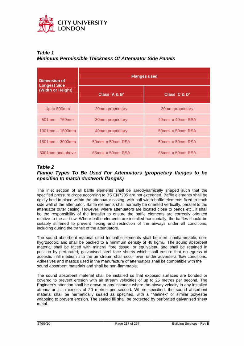
27/09/10 Page 217 of 257 Building Services - Rev B
Table 1 Minimum Permissible Thickness Of Attenuator Side Panels
Dimension of Longest Side (Width or Height)
Flanges used
Class ‘A & B’ Class ‘C & D’
Up to 500mm 20mm proprietary 30mm proprietary
501mm – 750mm 30mm proprietary 40mm x 40mm RSA
1001mm – 1500mm 40mm proprietary 50mm x 50mm RSA
1501mm – 3000mm 50mm x 50mm RSA 50mm x 50mm RSA
3001mm and above 65mm x 50mm RSA 65mm x 50mm RSA
Table 2 Flange Types To Be Used For Attenuators (proprietary flanges to be specified to match ductwork flanges) The inlet section of all baffle elements shall be aerodynamically shaped such that the specified pressure drops according to BS EN7235 are not exceeded. Baffle elements shall be rigidly held in place within the attenuator casing, with half width baffle elements fixed to each side wall of the attenuator. Baffle elements shall normally be oriented vertically, parallel to the attenuator outer casing. However, where attenuators are located close to bends etc., it shall be the responsibility of the Installer to ensure the baffle elements are correctly oriented relative to the air flow. Where baffle elements are installed horizontally, the baffles should be suitably stiffened to prevent flexing and restriction of the airways under all conditions, including during the transit of the attenuators. The sound absorbent material used for baffle elements shall be inert, nonflammable, non-hygroscopic and shall be packed to a minimum density of 48 kg/m3. The sound absorbent material shall be faced with mineral fibre tissue, or equivalent, and shall be retained in position by perforated, galvanised steel face sheets which shall ensure that no egress of acoustic infill medium into the air stream shall occur even under adverse airflow conditions. Adhesives and mastics used in the manufacture of attenuators shall be compatible with the sound absorbent materials and shall be non-flammable. The sound absorbent material shall be installed so that exposed surfaces are bonded or covered to prevent erosion with air stream velocities of up to 25 metres per second. The Engineer's attention shall be drawn to any instance where the airway velocity in any installed attenuator is in excess of 20 metres per second. Where specified, the sound absorbent material shall be hermetically sealed as specified, with a "Melinex" or similar polyester wrapping to prevent erosion. The sealed fill shall be protected by perforated galvanised sheet metal.

27/09/10 Page 218 of 257 Building Services - Rev B
The direction of air flow shall be clearly marked on the outer casing of each attenuator. Each attenuator shall also be clearly marked with a unit label which indicates the attenuator reference and location. Attenuators shall be delivered to site and stored with blocked ends to prevent ingress of dirt etc. Any damaged or soiled attenuators shall be removed from the site and replaced with factory new equipment at no additional cost to the contract. Site repairs are not acceptable. Cylindrical Absorptive Acoustic Attenuators Acoustic attenuators shall be purpose built units constructed by the Specialist Manufacturer, so designed and installed in the ductwork that they maintain all acoustic criteria shown in this specification, offer low resistance to air flow, have adequate strength and cohesion to resist erosion by air flow, and do not produce dust. Acoustic attenuators shall be of the same internal diameter as the ductwork in which they are installed. The Specialist Manufacturer shall provide the insertion losses expected from the attenuators for each of the 63Hz to 8000Hz octave frequency bands inclusive under the design operating conditions. These data shall include the air flow noise generated by the attenuators for each of the 63Hz to 8000Hz octave frequency bands inclusive under the design operating conditions. These attenuator acoustic performance data shall be derived from tests carried out in accordance with BS EN7235. The Specialist Manufacturer shall also provide the pressure losses expected from the installed attenuators at the design air volume flow rates and temperatures. These pressure loss data shall be derived from tests carried out in accordance with BS EN7235. The outer casings and pods, where installed, of the attenuators shall be constructed to comply with the relevant clauses of DW142 "high velocity" ductwork, in accordance with the design operating pressures and velocities of the ductwork systems in which they are to be installed. Attentuator casings shall be constructed from galvanised sheet steel with lockformed and mastic sealed joints and shall be fitted with intermediate stiffeners, where required, to comply with the requirements of DW142.
Maximum Diameter
Minimum Thickness
End Flange Casing
Up to 450mm 1.0mm 0.8mm
451mm – 825mm 1.2mm 1.0mm
826mm – 1350mm 1.6mm 1.2mm
1351mm – 2375mm RSC 1.2mm
27/09/10 Page 219 of 257 Building Services - Rev B
Table 3 Minimum permissible thicknesses of casings and flanges to be used for cylindrical attenuators. The inlet section of central pods shall be aerodynamically shaped such that the specified pressure drops according to BS EN7235 are not exceeded. The sound absorbent infill material used for central pods and side linings shall be inert, non-flammable, non-hygroscopic and shall be packed to a minimum density of 48 kg/m3. The sound absorbent material shall be faced with mineral fibre tissue, or equivalent, and shall be retained in position by perforated, galvanised steel face sheets which shall ensure that no egress of acoustic infill medium into the air stream shall occur even under adverse air flow conditions. Adhesives and mastics used in the manufacture of attenuators shall be compatible with the sound absorbent materials and shall be non-flammable. The sound absorbent material shall be installed so that exposed surfaces are bonded or covered to prevent erosion with air stream velocities of up to 25 metres per second. The Engineer's attention shall be drawn to any instance where the airway velocity in any installed attenuator is in excess of 20 metres per second. Where specified, the sound material shall be hermetically sealed or faced, as specified, with a "Melinex" or similar polyester wrapping to prevent erosion. The sealed fill shall be protected by perforated galvanised sheet metal. The direction of air flow shall be clearly marked on the outer casing of each attenuator. Each attenuator shall also be clearly marked with a unit label which indicates the attenuator reference and location. Attenuators shall be delivered to site and stored with blocked ends to prevent ingress of dirt etc. Any damaged or soiled attenuators shall be removed from the site and replaced with factory new equipment at no additional cost to the Contract. Site repairs are not acceptable. Acoustic Cross Talk Attenuators It shall be the responsibility of the Installer to supply and install acoustic cross talk attenuators where specified, and also wherever otherwise required, to prevent unacceptable levels of room to room sound transfer via common air transfer paths. The degree of cross talk attenuation that is provided via common ductwork between two rooms shall at least match the sound insulation offered by the building fabric separating those rooms. The general Specification of cross talk attenuators shall comply with the requirements for rectangular or cylindrical attenuators (clauses 8.3.1 or 8.3.21). Acoustic Duct Lagging It shall be the responsibility of the Installer to supply and install acoustic duct lagging where specified, and also wherever otherwise required, to achieve all specified noise criteria. In particular acoustic duct lagging shall be applied to all exposed ductwork in plant rooms unless otherwise specified.

27/09/10 Page 220 of 257 Building Services - Rev B
Acoustic duct lagging shall comprise an inner layer of 50 mm thick, 80-100 kg/m3 mineral wool, wrapped around the duct, and an outer impermeable mass barrier having a minimum superficial density of 5 kg/m2. The outer barrier shall not be in contact with the ductwork at any point. Joints between sections shall be overlapped by at least 100 mm and sealed using either a non-hardening mastic or preferably duct jointing tape. As an alternative to the acoustic duct lagging detailed in clause 8.3.26, proprietary acoustic duct lagging may be used with the agreement of the Engineers. Acoustic Louvres All acoustic louvre casings and blades shall be constructed from high quality galvanised sheet steel or aluminium of a suitable gauge and finished to the appropriate Specification and colour. Acoustic louvres shall be supplied with an integral bird screen on their inner faces. Bird screens shall be constructed from galvanised mild steel or aluminium mesh having a pitch of not more than 25 mm. The acoustic infill material in louvre blades shall be inert, non-flammable, nonhygroscopic and shall be packed to a minimum density of 48 kg/m3. The infill material shall be faced with mineral fibre tissue, or equivalent, and retained on the lower blade face by perforated or mesh galvanised mild steel or aluminium. Where acoustic louvres are specified by performance, the louvres shall provide an insertion loss under the operating conditions of not less than that indicated in the relevant acoustic hardware schedule. The acoustic louvres shall also not provide a pressure drop, under conditions of maximum operating duty, in excess of that specified in the relevant acoustic hardware schedule. Acoustic louvres shall be so designed and installed to prevent the ingress of rain etc. to the building under normally encountered weather conditions. All gaps between acoustic louvres and builder's work openings shall be sealed to maintain the acoustic and weather resistant properties of the external building fabric.
27/09/10 Page 221 of 257 Building Services - Rev B
VIBRATION CONTROL EQUIPMENT Vibration Isolators, General It shall be the responsibility of the Installer to supply and install vibration isolators where specified, and also wherever otherwise required, such that vibration generated by the engineering services installation including plant, pipework, ductwork and all ancillary items of equipment installed as part of the Works, does not cause any specified noise and vibration criteria to be exceeded. Where no vibration criteria are specified the installation shall not cause the maximum vibration amplitudes specified in BS 6472: 1984 to be exceeded. All mechanical plant likely to produce vibration that results in the specified noise and vibration criteria being exceeded shall be mounted on durable vibration isolators, with adequate lateral restraint. Vibration isolators shall be selected to be suitable for the loading, operating and environmental conditions which will prevail. Special attention shall be paid to vibration isolators which will be exposed to atmospheric or adverse interior conditions and appropriate finishes shall be applied to prevent excessive corrosion. The static deflection of vibration isolators shall be selected to give the necessary degree of isolation efficiency under the lowest normal operating speed of the isolated plant. Selection shall allow for asymmetric load distribution such that the minimum static deflection is achieved on all vibration isolators under normal operating conditions. All machines and bases shall be carefully levelled. Any vibration isolators which are "bottomed out", or where the springs have deformed from a cylindrical shape, shall be rejected and shall be replaced by the Installer at no extra cost to the Contract. All vibration isolators shall be colour coded or otherwise clearly marked to indicate rated load and deflection capacity to facilitate identification during installation. All external connections to vibration isolated plant shall be made using flexible connections. Particular care shall be taken to ensure that the connection of pipes, ducts, shafts, electrical conduit etc. to vibration isolated plant neither short circuits the plant vibration isolation, nor impedes the free movement of the vibration isolated plant. The vibration isolation system shall be selected to support the operating weight of the plant and equipment to be isolated only. All associated pipework, valves, filters, ductwork etc. and their contents shall be supported independently so as not to impose additional forces on the isolator system. All flexible connections shall be selected and arranged to accommodate this requirement. All pipework of 50 mm diameter and above and all ductwork shall be resiliently isolated from the building structure within plant rooms for a minimum of 15 metres from the motor driven plant. All plant, pipework and ductwork shall be resiliently isolated from any part of the building structure as specified, or as otherwise required, to achieve the specified noise and vibration criteria. Particular attention shall be paid to areas where low noise levels are specified. The mounting of any item of plant, pipework or ductwork from lightweight (stud) partitions shall preferably be avoided. If unavoidable, the Engineers shall be made aware of all such instances. The Installer shall also supply the Engineers with full details of the resilient mounting arrangements between the service item and the partition.
27/09/10 Page 222 of 257 Building Services - Rev B
Helical Spring Vibration Isolators Helical spring isolators shall be manufactured from sheet steel and springs of substantial thickness, and treated with a rust resistant protective coating. The isolators shall be provided with the necessary damping and load adjustment devices and shall incorporate rubber or neoprene elements in-series with the springs to prevent the transmission of high frequency vibration. The springs shall have an outside diameter of not less than 75% of the operating height, and shall be selected to have at least 50% overload capacity before becoming coil bound. Vibration isolators incorporating snubbers or restraining devices shall be so designed that these devices have no significant effect during the normal operation of the isolated plant. Rubber Or Neoprene Vibration Isolators Rubber or neoprene vibration isolators shall consist of a steel top plate and base plate completely embedded in oil-resistant neoprene. The isolators shall include a tapping through the top plate and bolt holes in the base plate so they can be bolted to the supporting structure and the isolated equipment as required. Helical Spring Vibration Isolation Hangers Helical spring hangers shall incorporate a helical steel spring of suitable thickness together with one or more rubber, neoprene or glass fibre elements inseries with the spring to prevent the transmission of high frequency vibration. The springs shall have an outside diameter of not less than 75% of the operating height, and shall be selected to have at least 50% overload capacity before becoming coil bound. Where the helical spring is housed in a steel cage, the clearance hole at the base of the cage and the cage itself should allow at lease 15o misalignment of the hanger rod before a vibration short circuit occurs. Rubber, Neoprene Or Glass Fibre Vibration Isolation Hangers Rubber, neoprene or glass fibre hangers shall incorporate a rubber, neoprene or glass fibre vibration isolation element housed in a steel cage. The clearance hole at the base of the cage and the cage itself should allow at least 15o
misalignment of the hanger rod before a vibration short circuit occurs. Spring Isolated Inertia Bases Spring isolated inertia bases shall be of a fully welded steel construction. The depth of the frame shall not be less than one twelfth of the largest dimension, or 100 mm, whichever is the greater. The frame shall include an appropriate quantity and distribution of height reducing spring fixing brackets. These spring fixing brackets shall either be mounted external to the frame, or recessed into the frame, as specified.

27/09/10 Page 223 of 257 Building Services - Rev B
The weight of the inertia base including concrete at approximately 2300 kg/m3, shall be equal to at least twice the total weight supported. The supported equipment and ancillary weights shall be arranged on the inertia base so as to distribute the load as evenly as possible over the mounting positions. The inertia base shall be sufficiently large to provide support for all parts of the equipment, including any parts that overhang the equipment base. The frame shall be supplied finished with red oxide primer unless otherwise specified. Neoprene Pad Isolated Inertia Bases Neoprene pad isolated inertia bases shall comprise a concrete base cast onto permanent shuttering, supported on neoprene pad(s) to give the required minimum static deflection, the whole resting on a plinth as required. The weight of the inertia base, including concrete at approximately 2300 kg/m3, shall be equal to at least twice the total weight supported. The supported equipment and ancillary weights shall be arranged on the inertia base so as to distribute the load as evenly as possible over the mounting positions. The inertia base shall be sufficiently large to provide support for all parts of the equipment, including any parts that overhang the equipment base. Flexible Connectors All external connections to vibration isolated equipment shall be made using flexible connections. Particular care shall be taken to ensure that the connection of pipes, ducts, shafts and electrical conduit to vibration isolated plant neither short circuits the plant vibration isolation, nor impedes the free movement of the vibration isolated plant. All flexible connectors shall be selected to achieve the specified noise and vibration criteria. Flexible connections on ductwork and pipework shall be as specified elsewhere. The aggregate stiffness of all flexible connections fixed to any one item of isolated plant shall be insignificant in relation to the stiffness of the supporting vibration isolators. Due allowance shall be made for the stiffening effect produced by the internal pressure, both negative and positive, of the system. Flexible connections shall be fitted between all fan inlets and outlets and their associated system ductwork. These acoustic flexible connections shall have a mean sound reduction index of not less than 22dB. The material shall comply with the requirements of flexible connections as specified elsewhere.
27/09/10 Page 224 of 257 Building Services - Rev B
PENETRATIONS IN BUILDING FABRIC Where ductwork passes through an acoustic barrier in the form of a wall or a floor the Installer shall make an airtight seal to the ductwork by densely packing mineral wool between the ductwork and the building fabric. The building fabric shall be lined by a galvanised sheet metal sleeve of one gauge heavier sheet than the duct passing through the opening. The mineral wool shall be held in place by large galvanised steel angle sections riveted to the ductwork but not fixed to the building structure. The angle shall be pushed tight against the mineral wool packing and the building fabric with an unbroken seal of flexible mastic between to prevent the direct transmission of duct borne vibration into the building structure. The angle shall overlap the hole by 10mm minimum all round. In exposed areas, if requested by the Engineers, a plywood frame shall be provided as an alternative to the angle flange. This shall be provided at no extra cost to the Contract. Where pipework penetrates the building fabric the pipes shall be suitably sleeved and sealed with a dense flexible mastic.

27/09/10 Page 225 of 257 Building Services - Rev B
APPENDIX A ACOUSTIC
COMMISSIONING TESTS FOR INTERNAL NOISE LEVELS

27/09/10 Page 226 of 257 Building Services - Rev B
Summary This document sets out a clearly defined test procedure for acoustic commissioning tests to establish room Noise Ratings due to the operation of the building environmental engineering systems. Specification For Acoustic Test Equipment All sound measurements shall be made with a precision sound measurement system conforming to the Type 1 requirements of BS 5979: 1981, or better. The sound measurement system shall be complete with all the facilities required to enable the specified measurements to be obtained. As a minimum the sound measurement system shall include:-
1 The facility to measure using both "slow" and "fast" time weighting charactertistics.
2 The facility to measure both "Linear" and "A" weighted sound levels over the frequency range 20Hz to 20kHz. The accuracy of the "A" weighting filter network shall conform to the Type 1 requirements of BS 5969: 1981, or better.
3 The facility to measure octave band filtered sound. The frequency weighting characteristics of the octave filter set employed shall conform to the requirements of BS 2475: 1964.
The sound measurement system shall be acoustically calibrated in absolute sensitivity at a reference frequency of 1000Hz. The calibration of the sound measurement system shall be performed immediately prior to, and immediately following, each series of test measurements. Any variations in sensitivity of greater than 0.5dB shall be recorded. Measurement Of System's Noise In Internal Areas In order to minimise the effects of extraneous background noise, all sound readings shall be taken with the test area of the building evacuated, with the exception of essential test personnel. In addition every effort shall be taken to minimise external noise intrusion to the building. All sound readings shall be taken under the two following conditions:-
1 All plant and machinery running normally, delivering the design conditions of ventilation, temperature and humidity (system's + background noise).
2 All plant and machinery switched off (background noise only).
The sound level in each octave frequency band from 63Hz to 8000Hz inclusive shall be recorded at each measurement location. In addition, the overall "A" weighted sound level shall also be recorded at each measurement location. All sound readings shall be made with the sound measurement system set to either the "Slow" time weighting, or set to "Leq" (equivalent continuous) if this facility is available. In each area of the building tested sound readings shall be taken at a minimum of five separate locations except where the room has a floor area of less than 9m2.
27/09/10 Page 227 of 257 Building Services - Rev B
The five measurement locations shall be chosen such that:-
1 No measurement location shall be closer than 1.0m from any surface, including walls, floor, ceiling, desk or partition.
2 No two measurement locations shall be closer than 1.0m to each other.
3 In offices a minimum of two measurement locations shall be at seated head
height (1.2m above floor level), and a minimum of two measurement locations shall be at standing head height (1.8m above floor level). In other areas the measurement locations shall be chosen according to the expected normal position for occupants of the room.
3 No measurement location shall be closer than 1.0m to any ventilation system
diffuser or grille.
Where the room has a floor area of between 4m2 and 9m2 two measurements shall be taken, and where the floor area is less than 4m2 one measurement shall be taken. These measurements shall be taken either at seated head height (1.2m above floor level) or standing head height (1.8m above floor level) depending on the expected normal position for occupants of the room. The octave band sound readings in each area shall be averaged over all measurement locations in that area. The average sound level in each octave frequency band shall then be plotted on a standard octave band Noise Rating (NR) curve. Both the background noise levels and the system's + background noise levels shall be plotted on the same NR curve. Where the system's + background noise level minus the background noise level lies between 3dB and 9dB in any octave frequency band, the effects of the background noise shall be accounted for in the evaluation of the system's noise. The corrected system's noise level shall be used to check for contractual deficiencies in that area. Where the system's + background noise level minus the background noise level is less than 3dB, then an accurate evaluation of the system's noise is not possible. In such cases in the event of contractual deficiency, the sound readings shall be deferred until the background noise decreases to at least 3dB below the system's + background noise (eg. during the evening or night time periods). The state of interior finish of the test area during the noise measurements will affect the measured noise levels. Where internal areas are not fitted out as per the occupied building, a correction factor (C) shall be added to the measured internal noise levels according to the equation C = 10 log10 (Tf/Tu) Tf is the measured or calculated reverberation time for the fully fitted out internal area under consideration. Tu is the measured or calculated reverberation time for the internal area under consideration at the time of the acoustic tests. The correction factor, C, shall be applied separately at each of the frequency bands measured. The correction factor shall not be applied in cases where the measured noise level is dominated by direct rather than reverberant noise.

27/09/10 Page 228 of 257 Building Services - Rev B
SECTION 9
TESTING AND COMMISSIONING

27/09/10 Page 229 of 257 Building Services - Rev B
General Commissioning Records Identify clearly as an integral part of the construction programme the periods representing the testing and commissioning of the engineering works and separately identify all associated costs at tender stage. Labour, Materials And Other Provisions Allow for all labour, materials, equipment and plant necessary to achieve the standards and performance specified for testing and commissioning. Provide all test equipment necessary for testing and commissioning performance testing and on request demonstrate that the instruments used are accurate within the permitted tolerances when compared with recognised standards. Provide copies of calibration certificates for all test instruments. Provide adequate specialist staff to operate and maintain the systems throughout the testing and commissioning procedures. Provide fuel, water and electricity as necessary for the execution of the specified works: For testing of sections of work, items of plant and each completed system. For commissioning, performance and acceptance testing and demonstration of all systems. Specialist Commissioning Engineer The entire commissioning and performance testing of the installation shall be undertaken by one of the approved Commissioning Specialists indicated. The Mechanical Contractor shall at all times be responsible for the supervision of the Commissioning Specialist's work and shall ensure satisfactory completion of commissioning and recording of results. The Specialist Commissioning Engineer shall be appointed at the most appropriate time in the construction period to ensure the necessary involvement and site visits for examination of drawings and exchange of information. Any deficiencies likely to affect the successful outcome of the commissioning shall be raised well in advance of the start of testing and commissioning. Commissioning Method Statement Submit well in advance of the programmed commissioning stage, a method statement showing full understanding of the testing and commissioning requirements. The statement shall set out the methods and resources to be employed at each stage of the process and a programme shall identify all the systems involved, their dependency on the operation of other mechanical and electrical systems, and on the availability of water, electricity and other energy sources. Rectification Of Defects
27/09/10 Page 230 of 257 Building Services - Rev B
Any defects of workmanship, materials, performance, maladjustments, noncompliance with this specification or other irregularities which become apparent during the tests or commissioning shall be rectified by the Mechanical Contractor, at his own expense, until the whole Works is free from defects and in full working order to the complete satisfaction of the Engineer. Repeat as necessary, until satisfactory, any testing and commissioning arising from rectification, at any stage, of defects in workmanship, materials, performance, misadjustments and other irregularities. Reports And Records Submit throughout the commissioning period, on a regular basis to be agreed, commissioning progress reports. Keep progressive records of testing and commissioning results and other 'as installed' information for completion of record drawings and operation and maintenance manuals. Witnessing And Notification The Engineer shall be given the opportunity to witness all tests. Allow a minimum of seven working days notice, in writing, for appropriate persons to attend inspections and witness tests or demonstrations at works or on site. Testing and commissioning of major items of proprietary plant or specialist equipment shall be carried out by the manufacturer's personnel and witnessed by the Commissioning Specialist. The Engineer shall be advised of such activities. Provide all necessary facilities and assistance for the employer's insurance company representative to attend inspections or witness tests as required.

27/09/10 Page 231 of 257 Building Services - Rev B
DEFINITIONS The definitions shall apply as listed in BSRIA Application Guides AG 2/89 and AG 3/89 for the Commissioning of Water and Air Systems in Buildings.

27/09/10 Page 232 of 257 Building Services - Rev B
TESTING AT WORKS Inspecting and testing at manufacturer's works of items of equipment, to comply with Standards or Codes of Practice, shall be carried out and witnessed as specified elsewhere. Duplicate test certificates for all works test shall be included in the operation and maintenance manuals.

27/09/10 Page 233 of 257 Building Services - Rev B
TESTING AT SITE General Carry out satisfactory pressure, air leakage and thermal expansion tests before application of paint, insulation or other cladding, as appropriate. Concealed Sections Of Work Individually test, in sections before concealment, any sections of a system to be permanently buried or concealed within the structure, void or duct. Pressure And Leakage Testing Carry out pressure and air leakage testing, in sections as work proceeds and to suit the construction programme. Carry out pressure and air leakage testing on complete systems, following any cleaning or scavenging, but before any disinfection or fumigation specified. Fill each system with appropriate hydraulic or pnuematic test medium at normal pressure and inspect for leakages. Apply the full pressure tests specified and with the pressurising equipment disconnected, hold these pressures for the period specified, without signs of leakage or distress to the system. Thermal Expansion Tests In conjunction with programme requirements bring steam, condensate, heating and hot water systems up to operating conditions, before allowing system to cool and again inspect for leakages. Protection Of System Equipment Isolate or remove from the system during pressure testing, items of equipment set to operate below test pressure. Expansion joints if not removed shall have expansion movement limited using bolts. Draining After Testing Drain completely pipework systems following testing and refill with clean water, treated water, preserving solution, inert gas or low pressure air as appropriate to suit the stage of the programme for the works and as recommended in B.2.1 Clause 5 of BSRIA Application Guide AG 2/89.

27/09/10 Page 234 of 257 Building Services - Rev B
STATIC PRESSURE TESTING Pipework Distribution Systems Comply with procedure and precautions in HVCA Guide to Good Practice for Site Testing of Pipework, HSE Guidance Note GS4 Safety in Pressure Testing and BS 4434 for Safety Aspects in the Design, Construction and Installation of Refrigerating Appliances and Systems. Comply with specified requirements foreach type of system. Precautions shall be taken to prevent danger to people and to minimize risk to property. In particular the dangers associated with pnuematic testing and the consequences of failure due to the stored energy in a compressed gas should be recognised. Steam, Condensate, Heating, Chilled Water And Glycol Pipework, Hot Water, Tank And Cold Water (Internal Domestic), Demineralised Water. Hydraulically pressure test for one hours duration as follows: Operating gauge pressure less than 3.5 bar; test gauge pressure 7.0 bar. Operating gauge pressure 3.5-7.0 bar; test gauge pressure twice operating pressure. Operating gauge pressure greater than 7.0 bar; test gauge pressure 14 bar or one and a half times operating pressure, whichever is the greater. Underground Pipework Generally Hydraulically pressure test to a gauge pressure not less than twice the operating pressure for a period of one hour. Mains Cold Water Pipelines (External Buried) Hydraulically pressure test in accordance with Local Authority requirements and HVCA Guide to Good Practice for underground ductile spun iron or polyethylene pipes, ie. spun iron 2 x mains pressure, PE 1½ x mains pressure or 10 bar, whichever is the greater. Where installers of polyethylene (MDPE) pipes such as Wavin or Durapipe are not used directly to install, the manufacturers assistance shall be obtained to ensure correct procedures for pressure testing. Fire Main Risers Hydraulically pressure test to 10 bar g measured at the top outlet and pressure maintained for at least 15 minutes. Demonstrate to the Fire Authority when tests are satisfactory and carry out required flow tests.

27/09/10 Page 235 of 257 Building Services - Rev B
Natural Gas Pipework Pnuematically leak and pressure test as laid down in HVCA Guide to Good Practice, British Gas Publications IM/5, IM/2 and as BS 5482 Part 1, BS 5410 Part 2, BSCP 331 as relevant. General Service Compressed Air And Nitrogen Pipework Pnuematically leak and pressure test as laid down in HVCA Guide to Good Practice. Leak test to 0.5 bar g. Pressure test to 1.5 x normal working pressure for a minimum of 2 hours with no visible distortion or leakage. Vacuum Pipework Pnuematically leak and pressure test as laid down in HVCA Guide to Good Practice. Leak test to 0.5 bar g. Pressure test to 6.9 bar g pressure for a minimum of 2 hours with no visible distortion or leakage. Gas Cylinder Pipework Testing and inspection in accordance with Section - 'Gas Cylinder Manifolds and Distribution Pipework'. Refrigeration Systems Testing and inspection in accordance with BS 4434 Section 4. Plant And Equipment Testing Tanks and cylinders operating at atmospheric pressure shall be tested under 'tank full' conditions for structural soundness and water tightness with no resulting distortion or leakages. Hydraulically test on site after erection, calorifiers and heat exchangers in accordance with BS CP.341. Fans after installation and in running order shall, unless otherwise agreed, be inspected for balance under supervision of the manufacturer's representative.
27/09/10 Page 236 of 257 Building Services - Rev B
INSTALLATION OF COMMISSIONABLE SYSTEMS General Follow the recommendations on planning, installation, inspection, reporting and documentation of Parts B1, B2, B3 and B4 BSRIA Application Guides AG 2/89, the Commissioning of Air Systems in Buildings, the CIBSE Commissioning Codes and HVCA DW Ductwork Specifications. Follow the defined position of the various parties in the commissioning process as set out in BSRIA Technical Memorandum TM 1/88 Commissioning of HVAC Systems - Division of Responsibilities. Particular attention shall be paid to the following: Protect sensitive or fragile items of plant and electrical equipment from dirt, damp and other damage. Observe manufacturers setting to work procedures and recommendations. Determine and record correct operation of automatic or manually operated sequence fire control, alternative working selection or duplicate plant changeover controls. Ensure safety in the event of failure of and following sudden resumption of electrical supply by correct operation of safety interlocks and equipment protection devices designed to protect personnel, such as those associated with the high voltage side of electrostatic filters and with remote electrically operated plant. Lock in their finally commissioned positions all regulating valves, dampers and devices, or where no locking included permanently mark final agreed setting positions. Ensure grease or lubricant is applied as required, for working parts at all times and prior to handover. Inaccessible positions shall have extended grease nipple points. Installation - Static Completion Achieve a state of readiness to commence commissioning when each commissionable system has been successfully completed as follows: Installed in accordance with the specification and drawings with all outstanding remedial works completed. Final installation inspection carried out, all mechanical and electrical inspection and pre-commissioning check lists completed. Successfully pressure and leak tested as specified. Flushed and cleaned and refilled or protected as specified. All test certificates, reports and manufacturer's information collated. Surrounding areas clean and free from obstruction for access to commissionable equipment.

27/09/10 Page 237 of 257 Building Services - Rev B
Identification and labelling complete. All dampers, valves, control devices, test points, gauges, thermometers and other specified items adjusted in good working order. With the installation checked safe mechanically and electrically for safe operation and ready for commissioning.

27/09/10 Page 238 of 257 Building Services - Rev B
IDENTIFICATION AND LABELLING Access Panels Mark on drawings positions of all ceiling tiles and other panels where access is required for commissioning and maintenance of items such as valves, drain cocks, stop cocks, trapping sets, controls, pressure switches, motors, dampers and test points. Provide and fix to the outside surface of all access ceiling tiles and enclosure panels, both hinged and demountable patterns, raised coloured discs or squares indicating the location of items of equipment. The coloured identification, means of fixing and display and charting for each individual location shall be agreed for the installation as a whole. Valve Labels All valves including automatic control valves forming part of the installations shall be provided with permanent and approved labels fixed securely in an agreed manner on to the valves. The pipeline and valve reference number shall be engraved or stamped in plain block letters on the labels. Self-adhesive labels shall not be used. The identifying number associated with each and every valve shall be recorded on the 'record' drawings. Manufacturer's Labels All mechanical and electrical equipment and plant (other than minor items) shall bear the manufacturer's name, together with any particulars required for its identification for the supply of spares and for its duty. The information may either be cast on, or stamped on to a plate securely fixed to the plant. Plant And Equipment Labels All mechanical plant and equipment shall, in addition to the manufacturer's labels, be suitably and clearly labelled with identification name, reference number and function in the particular installation, eg. "Pump No. 2, Constant Temperature Heating", which shall be as shown on the 'record' drawings. All specified electrical plant and equipment fixed or handed to others for fixing shall be suitably and clearly labelled with identification name, reference number and function in the particular installation. Thermostats and all other equipment with adjustable settings shall have in addition on the label their normal or rangeof normal settings. Permanent and approved labels, engraved or stamped in plain block letters, shall be fixed by screws or nuts and bolts to the wall adjacent or directly on the plant and equipment as appropriate. Where it is more convenient to do so, eg. for small electrical equipment, printed wall charts giving the above information shall be fixed in convenient and logical positions and the plant or equipment labels only consist of a references number.
27/09/10 Page 239 of 257 Building Services - Rev B
Identification names and reference numbers shall be as those shown on the 'record' drawings. Wall Charts Provide and fix in convenient and appropriate positions the following printed wall charts, framed with hard back and glass front or photographically printed on laminated plastic black on white or suitably engraved dual colour melamine sheet. The final positions shall be agreed before fixing. Schematic layout of the mechanical installation - a fully detailed drawing with each pipeline and system clearly identified. Valve charts - giving the pipeline, operation and position of all labelled valves. 'Method of operation' wall chart adjacent to each control panel. 'Identification of pipeline' - an explanatory wall chart in tabular form, setting out the colour codes. Identification of pipelines shall be to BS 1710 Appendix D table 3. Identification of ductwork shall be to HVCA DW/142. Identification names, reference numbers, etc, shall be as those shown on the 'record drawings'.
27/09/10 Page 240 of 257 Building Services - Rev B
COMMISSIONING PROCEDURES Commissioning Codes Commission installations in accordance with the procedures, checks and tolerances provided in the CIBSE Commissioning Codes and BSRIA Application Guides. Preliminary Checks - Water Distribution Carry out checks and procedures in accordance with CIBSE Commissioning Code W, section W1 and check lists in BSRIA Application Guide AG 2/89 section D3. Preliminary Checks - Air Distribution Carry out checks and procedures in accordance with CIBSE Commissioning Code A section A1 and check lists in BSRIA Application Guide AG 3/89 section D3. Setting To Work And Regulation – Water Distribution Set to work and regulate water distribution systems in accordance with CIBSE Commissioning Code W section W2 and procedures in BSRIA Application Guide AG 2/89. Use instruments for measurement detailed in BSRIA Application Guide AG 2/89 section C2. System design performance, flow rates, velocities, pressure loss and locations of flow measurement and regulation devices shall be as provided on the drawings, specifications or separate schedules. Regulating valves shall be adjusted to provide specified water flows free from excessive water turbulence and unacceptable noise. Test points shall be located at appropriate positions in the pipework where water turbulence is minimal. Allow for one change of pulley and/or belts for each pump drive, as necessary when operating the pump units and measuring the actual system characteristics, to achieve the specified performance. Following successful commissioning main cold water and potable hot and cold water pipeline systems shall be disinfected in accordance with BS 6700 clauses 13.9.3 and 13.9.4 and certification provided.
27/09/10 Page 241 of 257 Building Services - Rev B
Setting To Work And Regulation – Air Distribution Set to work and regulate air distribution systems in accordance with CIBSE Commissioning Code A section A2 and procedures detailed in BSRIA Application Guide AG 3/89 section 4. Regulate variable volume systems in accordance with routine recommended in BSRIA Technical Note TN 1/78. Use instruments and methods of measurement detailed in CIBSE Commissioning Code A Appendix A3.1 and in BSRIA Application Guide AG 3/89 section C2. In addition to the basic recommended kit, electronic instruments will be allowed providing they are accurate and have up to date test certificates. System design performance, flow rates, velocities, pressure loss and locations of flow measurement and regulation devices shall be as provided on the drawings, specifications or separate schedules. Determine the air quantities by the velocity pressure method, using a pitot tube and inclined gauge manometer or electronic manometer. Where due to space limitations or air turbulence within the ductwork the total air quantity cannot be determined by the velocity head method, this shall be determined by using an accurately calibrated manometer at the main outlet or discharge louvres. Likewise for the same conditions, the air quantities at the inlets or outlets or branch ducts may be added to provide a result for the branch duct connection. Ductwork dampers, diffusers and grilles shall be adjusted to provide specified air movement without draughts and free from excessive air turbulence and unacceptable noise. Test points shall be located at appropriate positions in the ductwork where air turbulence is minimal. Allow for one change of pulley and/or belts for each fan drive, as necessary when operating the fan units and measuring the actual system characteristics, to achieve the specified performance. Commissioning Refrigeration Systems Follow the procedures given for use and handling of refrigerants, pressure and leak testing, evacuation and dehydration, charging and lubrication of refrigeration systems in CIBSE Commissioning Code R and manufacturer's instructions. Carry out procedure for preliminary checks, testing, charging, setting to work and adjusting for reciprocating compressor systems detailed in CIBSE Commissioning Code R section RR. Use instruments and apparatus detailed in CIBSE Commissioning Code R Appendix RG 8.1. Apply tolerances defined in Appendix RG 8.2. Commissioning Automatic Control Systems Carry out commissioning of automatic control systems in accordance with control equipment manufacturer's manual. Carry out the checking and setting up procedures detailed in CIBSE Commissioning Code C section C1. Carry out measurements in accordance with CIBSE Commissioning Code C Appendix C2.1. Ensure control systems are commissioned in conjunction with air and water distribution systems.

27/09/10 Page 242 of 257 Building Services - Rev B
Heat Testing On satisfactory completion of the commissioning of the heating system(s), hot water system(s) and all associated equipment the completed systems shall be operated at design temperatures and pressures for a period of at least 8 hours. The systems shall be allowed to cool down and examined for defects. Any defects shall be rectified and the particular system(s) re-tested until satisfactory. On completion all gauges, controls and thermostats shall be reset to the agreed specified normal operating values.

27/09/10 Page 243 of 257 Building Services - Rev B
PERFORMANCE AND ACCEPTANCE TESTING All systems and plant shall be fully commissioned to the design performance specification and satisfactory results obtained before arrangements are made for performance demonstration and acceptance of any system. Record sheets as detailed in BSRIA Application Codes AG 2/89 and AG 3/89 shall be used to establish results, actual and design, for the final acceptance of the commissioning and performance testing stages. Demonstrate each commissioned system or item of plant in a manner appropriate to the function and performance requirement that each system or items of plant performs correctly, provides the duties required and maintains conditions within the specified limits under varying plant loading. Specialised installations including computer rooms, clean rooms, animal rooms and other close-control applications, will be required to achieve satisfactory system performance when subject to artificial internal and external loads. Acceptance tests shall include the proper functioning of automatic controls and protective and alarm devices, as well as the demonstration that the commissioning results are acceptable ie. within accepted tolerances. Unacceptable results shall require the system be re-commissioned following any necessary adjustments or modifications. All necessary calibration data, pump and fan curves, characteristics and details of plant duty shall be readily available on site, together with copies of all commissioning results and a set of 'record drawings' of the installation showing plant settings, air volumes, fan pressures, temperatures, water flow rates, pump heads and noise level readings as adjusted and measured during the commissioning and performance testing period. These shall be included in the Commissioning and Testing Report. Performance tests shall be carried out on the mechanical engineering systems at a time when outside conditions permit the system to operate in the region of their maximum winter duty and in the case of cooling systems at their maximum summer duty. It is unlikely that demonstration will be possible of both summer and winter conditions before building handover. Therefore, a revisit shall be made to site after the building is completed to carry out outstanding seasonal environmental tests. Stability of room temperature and humidity control shall be demonstrated by the installation of thermohydragraphs in selected rooms to record temperatures and humidities over a minimum of three days. The number and positions shall be agreed in advance with the Engineers. The corresponding external conditions shall also be recorded whilst tests are in progress.
27/09/10 Page 244 of 257 Building Services - Rev B
SOUND LEVEL MEASUREMENTS Readings shall be taken to ensure that the required noise ratings are not exceeded. Measurements shall be made in accordance with Section - 'Noise and Vibration Control, Appendix A'. The acoustic performance of atmospheric silencers, items of plant where limitations on permitted noise levels are specified and the noise transmission from plant room areas shall be measured, recorded and assessed as indicated. Wherever necessary, when measuring room sound levels, normal continuous background noise from sources other than the installation shall be taken into account. Measurements relating to overhead terminals shall be taken directly below each terminal at 1.7 m above floor level, and for sidewall terminals, 1 m horizontally and 1.7 m above floor level. Results of octave band analysis shall be submitted on noise rating curve charts for each individual space. Tests shall be carried out using a sound level meter, with frequency analyser, meeting requirements for Type 1 of BS 5969.

27/09/10 Page 245 of 257 Building Services - Rev B
COMMISSIONING AND TESTING REPORT Report Content Prepare and supply two copies of the typed commissioning report, each bound or presented in a ring binder, sectioned with index to cover each engineering service, which shall be based on the CIBSE Commissioning Codes and include the following topics:
Works test certificates. Site certificates. Commissioning inspection reports. Commissioning results and final settings. Performance and acceptance test reports.
Air Handling Equipment Commissioning Sheets Air handling equipment commissioning sheets shall include specified and test results against the following:
System and/or fan number and description. Air handling equipment manufacturer. Fan manufacturer, model, type and size. Total air volume (m3/s). Return air volume (m3/s). Outside air volume (m3/s). Total static pressure (Pa). Suction static pressure (Pa). Discharge static pressure (Pa). Fan speed (rpm). Sizes of pulleys. Belt sizes and numbers. Motor manufacturer. Name plate rating (phase/volts/amps/rpm). Final operating amperage. Coil pressure drop.
27/09/10 Page 246 of 257 Building Services - Rev B
Filter pressure drop. Provide fan curve with operating point marked on.
Exhaust/Extract Fan Commissioning Sheets Fan commissiong sheets shall include specified and test results against the following: System and/or fan number and description.
Fan manufacturer, model, type and size.
Total air volume (m3/s).
Total static pressure (Pa). Suction static pressure (Pa). Discharge static pressure (Pa). Fan speed (rpm). Sizes of pulleys. Belt sizes and numbers. Motor manufacturer. Name plate rating (phase/volts/amps/rpm). Final operating amperage. Provide fan curve with operating point marked on.
Diffusers, Grilles And Registers Commissioning Sheets Diffuser, grille and register commissioning sheets shall include results against the following items:
System and/or zone number and description. Room number or area designation. Outlet code number (which shall correspond to code number of outlet on air balance code drawing). Manufacturer of outlet. Type of outlet - per manufacturers model designation. Size of outlet - manufacturers listed size. Manufacturers effective area for each size. Required air velocity (m/s) and air flow rate (m3/s) of each outlet. Initial test velocity and flow rate of each outlet.

27/09/10 Page 247 of 257 Building Services - Rev B
Final balanced velocity and flow rate of each outlet.
Test Code Drawing For Air Systems Line drawings of each air distribution system shall be provided, stating system and/or zone numbers, indicating numbers for each and every item of plant and fan, heat exchanger, test point, regulating damper and outlet (both supply and extract). Water System Commissioning Sheets The water system commissioning sheets shall list the specified and test results against each and every plant item, including heat exchangers and automatic valves against the following: Balance of water distribution systems showing flow rates, control valve duties including valve performance data charts. Valve control settings. Commissioning data supplied by specialist plant equipment manufacturers. Pump Commissioning Sheets Pump commissioning sheets list the specified and test results against the following:
System and/or zone number and description.
Manufacturer, model, type and size.
Flow rate (l/s).
Entering water temperature (OC).
Leaving water temperature (OC).
Pressure drop (kPa).
Operating suction and discharge pressures and final total discharge head of each pump.
Pump speed (rpm).
Sizes of pulleys.
Belt sizes and numbers.
Motor manufacturer.
Name plate rating (phase/volts/amps/rpm).
Final operating amperage.
Provide pump curve with operating point marked on.
27/09/10 Page 248 of 257 Building Services - Rev B
Heating And Cooling Coil, Run-Around Coil, Air & Water Plate Heat Exchangers And Heat Wheel Commissioning Sheets Commissioning sheets shall list the specified and test results for every item of heat exchange equipment against the following:
System and/or coil number and description.
Manufacturer, model, type and size.
Air flow rate (m3/s).
Air pressure drop (Pa).
Entering air dry bulb temperature (OC).
Entering air wet bulb temperature (OC).
Leaving air dry bulb temperature (OC).
Leaving air wet bulb temperature (OC).
Water flow rate (l/s).
Water pressure drop (kPa).
Entering coil water temperature (OC).
Leaving coil water temperature (OC).
Outside air dry bulb temperature (OC).
Outside air wet bulb temperature (OC). Test Code Drawing For Water Systems Line drawings of each water distribution system shall be provided, stating system and/or zone numbers, indicating numbers for each and every item of plant and pump, heat exchanger, test point, regulating valve and outlet.
27/09/10 Page 249 of 257 Building Services - Rev B
PERFORMANCE AND ACCEPTANCE TEST RESULTS Performance and Acceptance Test sheets shall include the following information both specified and actual:
Control settings for all plant.
Control settings for control panel equipment.
Set points included in building management systems.
Record of temperature and pressure test points.
Record of positions of all regulating devices.
Record of temperatures in all occupied spaces together with associated outside conditions.
Record of relative humidities in all rooms that are air conditioned.
Noise level readings of plant and equipment.
Noise level reading in occupied spaces.
Approvals Once the installations are in a suitable condition arrange for inspections to take place by statutory bodies and others who are required to give approval to any of the Engineering Systems. These shall include the following: Local Water Authority Approvals shall be obtained in writing and copies of the approvals shall be included in the Operating and Maintenance Instructions.

27/09/10 Page 250 of 257 Building Services - Rev B
RECORD DRAWINGS During the progress of the Works, prepare and maintain copies of draft record drawings. These drawings are to be kept on site and marked up by a competent person to indicate: All variations in positions, runs, sizes and types of equipment, ductwork, trunking, cables, valves, pipes etc. Details of all circuiting, fuseboard arrangements and equipment labels. Record of position of buried external services. Completed record drawings clearly marked "Record" or "As Installed" shall be provided in sufficient time to be incorporated as part of the Operating and Maintenance Instructions. Such drawings shall generally include: The layout, location and extent of all piped services including sizes, valves for isolating, regulating, draining, venting and other purposes. The layout, location and extent of all ducted services including sizes, dampers, diffusers, grilles, silencers and other associated equipment. The location, identity and size of all apparatus and control equipment served by or associated with each of the services. Locations of all test points for water, air, oil and gas systems. Detailed general arrangements of the plant rooms, equipment and other plant or apparatus as appropriate. Comprehensive schematic line drawings of each air and water distribution system showing flow details and the principles of operation. Where appropriate manufacturers details drawings for all plant and equipment installed. Comprehensive diagrams of electrical and control wiring details for all services, plant and equipment, showing the principles of operation, application of automatic controls and instrumentation and all electrical power and control wiring for each of the various services. All record drawings shall be in Autocad format and as drawing files, Labelling of CD’s as City University standard. A test plot and CD shall be offered to City University for validation.

27/09/10 Page 251 of 257 Building Services - Rev B
OPERATING AND MAINTENANCE INSTRUCTIONS Operating and Maintenance Manuals shall be provided, at or before date of practical completion, comprising the following information and complete in all respects as outlined in the General Conditions and Preliminaries. The manuals shall be type written throughout, incorporating a fully comprehensive index with all pages numbered. A general description of the scope, the installation, the plant and functional performance of each of the systems provided, clearly stating plant component arrangements and intended mode of operation. The basis of design and normal operating conditions of the installed systems. A detailed description of the scope and functional requirements of the automatic controls and monitoring installation for each of the systems provided, together with a detailed description of the method of control and final settings of environmental control conditions. "Method of Operation" saying in laymen's terms, with step-by-step instructions, how to turn all plant on and off, and how to operate it, detailing the operation of all safety devices. Comprehensive instructions for the running, operation and maintenance requirements including nature, extent and frequency of servicing for planned preventative. These shall include safety checks and maintenance and test procedures to avoid infection such as Legionella. Description of emergency action which should be taken and schedule of procedure for fault finding in the event of equipment or system failure. Copies of manufacturers data with respect to the nature, type and method of operation of individual pieces of equipment together with their detailed maintenance instructions. Manufacturers' literature, test certificates, detailed drawings and electrical circuit details, printed operation and maintenance instructions, for all specific items of equipment and plant supplied and systems consisting of such equipment and plant. A list of suppliers and manufacturers names, addresses and telephone and fax numbers. Schedules of equipment with manufacturers' reference numbers and name plate data. Schedules of spare parts etc including itemised specifications, identification numbers and sources of supply. Schedule of lubricants for use with each plant item is to be included. Electrical "Record" drawings and control wiring diagrams identifying correct fuse ratings and adjusted thermal overload settings. Wiring diagrams of plant interconnections and internal wiring of equipment.
Mechanical "Record" drawings. Testing and commissioning records.
27/09/10 Page 252 of 257 Building Services - Rev B
Details of any Operational Tests necessary for appropriate items plant or equipment. Method of adjustment and fault finding routine for appropriate items plant or equipment.
Paper copies of all wall charts. Details of all filters (including manufacturer, part number, description, size, quantity, price per unit).
Approval letters from Statutory Bodies and others. Draft copies shall be available at the commencement of the commissioning process. All the above information shall be bound into an A4 ring binder with hard covers; where the original information is on different sized paper it shall be copied on to A4 paper or reduced to A4 size where necessary. Drawings shall be folded and put in plastic files and bound in the ring binder. Some of the above information required to be provided in the Commissioning Reports shall also be incorporated as detailed. If the commissioning report is suitably structured, suitable sections may be reproduced in the operating and maintenance instructions. The Operating and Maintenance Manual shall be in Microsoft Word . A test print and disk shall be offered to City University for validation.

27/09/10 Page 253 of 257 Building Services - Rev B
INSTRUCTIONS TO EMPLOYER'S STAFF At times to be agreed and prior to Handover, instruct the employer's staff in the use and correct operation of the Works and obtain satisfaction that such staff are competent to take over the installation on completion.
27/09/10 Page 254 of 257 Building Services - Rev B
SPARES, TOOLS AND CONSUMABLES Supply prior to handover, in suitable containers, the following spares, tools and consumables: 3 - No. Air cock keys. 3 - No. Keys for all sizes of lockshield valves. 3 - No. Control key for all inlet and outlet air devices. 6 - No. Valve packings for each type of valve installed. 1 - No. Gland packing for each pump (where necessary). 1 - No. Set Vee rope drives for each motor, labelled to denote plant to which they apply. 1 - No. Complete set of joint rings for each calorifier provided under this Specification . 3 - No. Sets of joint rings for each size of flange installed. 1 - No. Set of spanners to fit all nuts on plant and pipework. 1 - No. Set of spare fuses for all control equipment. 1 - No. Complete set of replacements for all filters. 1 - No. fusible link mechanism per 10 no. fire/smoke dampers. An initial 12 months supply of all oil and grease recommended by the manufacturers for the normal operation of the plant, together with suitable filling cans and grease gun(s). Loose spare, tools and loose equipment specified elsewhere. All the above shall be properly packed and labelled and handed over to the Client's Representative with a detailed schedule in triplicate, to be signed by the Client's Representative on receipt of the materials listed. A copy of the receipt is intended for both parties, and the third copy shall be handed to the Supervising Officer.

27/09/10 Page 255 of 257 Building Services - Rev B
PRACTICAL COMPLETION OF THE WORKS A Certificate of Practical Completion will not be issued until the installation is complete and working to the satisfaction of the Engineer and, in particular, to include the following items:
Engineering installation has been completed and snags rectified.
Identification and labelling of valves, pipework and ductwork has been provided.
Commissioning and Testing Report has been provided.
Performance and Acceptance Tests have been carried out. "As Installed" record drawings have been provided. Operating Instructions and Maintenance Manuals have been provided. Spares have been provided. Employer's Staff have been instructed in the correct operation of the installation . Approvals received from Statutory Bodies and others.
27/09/10 Page 256 of 257 Building Services - Rev B
REFERENCE DOCUMENTS Where reference is made to a British Standard (BS) a British Standard Institution recognised equivalent European Standard would also comply (See latest BSI Standards Catalogue etc). Each type of equipment/material selected shall comply fully with either the BS or the European Standard. HSE GS4 Guidance note. Safety in Pressure Testing. DOH Hospital Technical Memorandum No. 22 HVCA Guide to Good Practice for Site Pressure Testing of Pipework. HVCA DW143 A Practical Guide to Ductwork Leakage Testing. CIBSE Commissioning Codes - Series W, 1989 Water Distribution Systems. CIBSE Commissioning Codes - Series A, Air Distribution. CIBSE Commissioning Codes - Series B, Boiler Plant. CIBSE Commissioning Codes - Series R, Refrigerating Systems. CIBSE Commissioning Codes - Series C, Automatic Controls. BSRIA AG 8/91 Application Guide: Flushing and Cleaning of Water Systems. BSRIA AG 2/89 Application Guide: The Commissioning of Water Systems in Buildings. BSRIA AG 3/89 Application Guide: The Commissioning of Air Systems in Buildings. BSRIA AG 1/91 Application Guide: The Commissioning of VAV Systems in Buildings. BSRIA TM 1/88 Technical Memoranda: Commissioning HVAC Systems - Division of Responsibilities. BSRIA TN 1/78 Technical Note: Air System Balancing - Regulating Variable Flow Rate Systems. BS 5306 Code of Practice for Fire Extinguishing Systems. BS 5482 Part 2 Code of Practice for Oil Firing. BSRIA 1/88 Commissioning of HVAC Systems - Division of Responsibilities. BS 5482 Code of Practice of Butane and Propane Gas – Burning Part 1 Installation. BS 6700 Design, installation, testing and maintenance of services supplying water for domestic use. BS 1710 Specification for Identification of Pipelines and Services. BS 6230 Code of Practice for gas fired forced convection air heaters not exceeding 100 kw. BS 5864 Code of Practice for gas fired ducted air heaters not exceeding 60 kw.

27/09/10 Page 257 of 257 Building Services - Rev B
BSCP 331 Code of Practice for Installation of Low Pressure Towns Gas. BS 341 Central Heating by Low Pressure Hot Water. BS 4434 Safety Aspects in the Design, Construction and Installation of Refrigerating Appliances and Systems.