Building Services
72
SCHOOL OF ARCHITECTURE, BUILDING & DESIGN BLD60903 BUILDING SERVICES PROJECT 2 ANALYSIS AND DOCUMENTATION OF BUILDING SERVICES SYSTEM Ting Peng Hang 0313515 Eric Lai Yiew How 0313843 Gabriel Liew Chung Hooi 0314126 Kelvin Cheong Cheng Lee 0310354 Benard Chin Tze Yong 0313355 Danar Jovian Aditya Vadya Putra 0314575
-
Upload
eric-lai -
Category
Environment
-
view
517 -
download
2
Transcript of Building Services

SCHOOL OF ARCHITECTURE, BUILDING & DESIGN
BLD60903
BUILDING SERVICES
PROJECT 2
ANALYSIS AND DOCUMENTATION
OF
BUILDING SERVICES SYSTEM
Ting Peng Hang 0313515
Eric Lai Yiew How 0313843
Gabriel Liew Chung Hooi 0314126
Kelvin Cheong Cheng Lee 0310354
Benard Chin Tze Yong 0313355
Danar Jovian Aditya Vadya Putra 0314575

BUILDING SERVICES [ARC 2423] PROJECT 2 : CASE STUDY & DOCUMENTATION OF BUILDING SERVICES SYSTEMS
1
TABLE OF CONTENTS
ABSTRACT
ACKNOWLEDDGEMENT
INTRODUCTION
4
5
6
1.0 FIRE PROTECTION SYSTEM
1.1 Introduction
1.2 Literature Review
1.2.1 Active Fire Protection System
1.2.2 Passive Fire Protection System
1.3 Active Fire Protection System
1.3.1 Water Sprinkle System
1.3.2 Wet Riser and Hose Reel System
1.3.3 Pump Control Room
1.3.4 Duty Pump
1.3.5 Smoke Detector
1.3.6 Roller Shutter
1.4 Passive Fire Protection System
1.4.1 Fire Wall
1.4.2 Fire Rated Door
1.4.3 Smoke Curtain
1.4.4 Separation of Fire Risk Area
1.4.5 Emergency Exit Signage
1.4.6 Fire Resistant Escape Stairs
1.5 Conclusion
7
11
22
2.0 AIR CONDITIONING SYSTEM
2.1 Introduction
2.2 Literature Review
2.3 Finding and Analysis
2.3.1 VRV / VRF ( Variable Refrigerant Flow
) air conditioning system
33

BUILDING SERVICES [ARC 2423] PROJECT 2 : CASE STUDY & DOCUMENTATION OF BUILDING SERVICES SYSTEMS
2
2.3.2 Basic Refrigeration Cycle
2.4 Components
2.4.1 Outdoor Units
2.4.2 Indoor Units
2.5 Conclusion
3.0 MECHANICAL VENTILATION SYSTEM
3.1 Introduction
3.2 Literature Review
3.3 Air Handling Unit (AHU)
3.4 Industrial Circular Fan
3.5 Air Duct System
3.5.1 Single Duct System
3.5.2 Double Duct System
3.6 Exhaust Ventilation
3.7 Conclusion
41
4.0 MECHANICAL TRANSPORTATION SYSTEM
4.1 Introduction
4.2 Literature Review
4.3 Operation Of Lift System
4.4 System Components
4.4.1 Lift System ( A ) Machine –Room Less Lift
4.4.2 Machine-Room Less System
Components
4.4.3 Lift System ( B ) Geared Traction Lift
4.4.4 Geared Traction Elevator System
Components
4.4.5 Machine Room
4.5 Fire Lift System
4.6 Conclusion
50

BUILDING SERVICES [ARC 2423] PROJECT 2 : CASE STUDY & DOCUMENTATION OF BUILDING SERVICES SYSTEMS
3
GENERAL CONCLUSION
REFERENCES
69
70

BUILDING SERVICES [ARC 2423] PROJECT 2 : CASE STUDY & DOCUMENTATION OF BUILDING SERVICES SYSTEMS
4
ABSTRACT In this report, we will do analysis and research on the details and services that can be found in
Hap Seng Sdn.Bhd, Balakong Autohaus (Mercedes-Benz Autohaus). Services that we will look into
are fire protection system which include active and passive, mechanical transport system,
mechanical ventilation and also air conditional. By having analysis on these services, we are
aware that the importance role played by these service in a building’s operation. After having all
the informations from the analysis and researches, we will conduction a conclusion to these
services based on our understanding regards to Uniform Building By-Law as well as other rules
and regulations.

BUILDING SERVICES [ARC 2423] PROJECT 2 : CASE STUDY & DOCUMENTATION OF BUILDING SERVICES SYSTEMS
5
ACKNOWLEDGMENT We would like to extend our deepest gratitude to each individual that has helped and assisted in
completing this research report. Special thanks to the person in charge of building services
department, Mr Lian who had given his precious time, providing good hospitality during our site
visit. He has been very kind in providing us as much information as he can, bringing us around
the building and providing explanations and answers to our questions and curiosity.
We would also like to thank Ms. Ateerah Hassan who has given us the permission to do an in-
depth study on the systems that runs in Hap Seng Star Sdn Bhd, Balakong Autohaus. In addition,
we would like to express our deepest appreciation for providing us with guidance to complete
this report and giving us a substantial amount of suggestions during our tutorial sessions. We
would also like to thank each of our members that have put a lot of effort in cooperating with
each other. By all means, we would like to thank once again to everyone who had helped in
making this project a success.

BUILDING SERVICES [ARC 2423] PROJECT 2 : CASE STUDY & DOCUMENTATION OF BUILDING SERVICES SYSTEMS
6
INTRODUCTION
Mercedes-Benz Autohaus (Balakong Autohaus) is a newly built showroom. It was designed by
Asima architect. Hap Seng Star appears to be one of the primary authorized dealers of Mercedes-
Benz vehicles. Mercedes-Benz Autohaus located prominently at Balakong and with the RM60
million facilities raises the standard in the showroom and customer service even further more.
The built-up area for this autohaus is 140,000 sq ft. This Balakong Autohaus is the sixth opening
for Mercedes-Benz autohaus. In addition, this new autohaus was placed in a strategic location
where is it close to major highways and afford it a large catchment area.
Their aim for this autohaus to to provide a spacious building to serve every need of their customer
and also exceptional experience. This autohaus provide wide range of services to their customers
which include after sale services and repairs, with body and paint works repair.

BUILDING SERVICES [ARC 2423] PROJECT 2 : CASE STUDY & DOCUMENTATION OF BUILDING SERVICES SYSTEMS
7
1.0 FIRE PROTECTION SYSTEM
1.1 Introduction
Every building has a fire safety feature because it helps to ensure the safety of the user especially
in big building because evacuation consume large amount of time. In this chapter, the main
analysis consists of active fire protection and passive fire protection system in Hap Seng Star Sdn
Bhd, Balakong Autohaus.
Fire protection is divided into two system which is the active fire system and passive fire system
and details are being studied and explained later. There are rules and regulation set by Bomba
for each building and this research paper had concluded the analysis. After analysis both
regulation and fire system in the building, recommendation and improvement are also
suggested.

BUILDING SERVICES [ARC 2423] PROJECT 2 : CASE STUDY & DOCUMENTATION OF BUILDING SERVICES SYSTEMS
8
1.2 Literature Review
1.2.1 Active Fire Protection System
The definition of fire is a process of rapid oxidation of a material in the exothermic chemical
process of combustion, releasing heat, light, and various reaction products. It is a visible effect of
the process called “combustion” which is a type of chemical reaction. A fire can spread 4.6 meters
per second (Binggeli, 2014). Fire occurs when there is presence of air and some sort of fuel. The
product from the chemical reaction is totally different from the starting material.
In order to allow combustion to occur, the fuel must be heated to its ignition temperature. This
chemical reaction will continue to process as long as there is enough heat, fuel and oxygen and
this is also known as the fire triangle.
FUEL – Any combustible material in any state: solid,
liquid or gas. Solid and liquid will undergoes changes
in state and become vapor (gas) after burning.
OXYGEN – The air that we breathe in everyday
consist of 21% of oxygen. To allow combustion to
occur, at least 16 percent of oxygen is needed.
HEAT – The energy required to increase the
temperature of the fuel to the ignition temperature
in order to have combustion process.
To produce a fire, 4 elements are must be present at the same time which is:
1. Fuel or combustible material
2. Sufficient oxygen to maintain the process combustion
3. Exothermic reaction of the fire
4. Sufficient heat to maintain the ignition temperature
Speeds of combustion are depending on the amount of oxygen available. There are few chemical
reaction occur in the combustion process. Burning fuel will only produce only water and carbon
dioxide (no smoke or other product) in a compete combustion. In order for complete combustion
to happens, there need to be sufficient oxygen to combine completely with the fuel gas.
Fuel + Oxygen (from the air) = combustion product (mainly CO2 + H2O) + Heat Energy

BUILDING SERVICES [ARC 2423] PROJECT 2 : CASE STUDY & DOCUMENTATION OF BUILDING SERVICES SYSTEMS
9
Cost-effective passive and automatic fire protection systems need to be designed to
incorporate efficient in new facilities and renovation projects. Passive and automatic fire
protection systems are effective in detecting, containing, controlling and extinguishing a fire
event in the early stage. In every building, the fire engineer are required to ensure a reasonable
degree of protection of human life from fire and the product combustion as well as to reduce
the potential loss from fire.
The basic goals of fire protection In a building is to:
1. Save life
2. Save properties
3. Preserving business continuity
Different types of building will have different types of fire protection requirements depends on
how a building is being used or occupied. The systems found in any building typically include
theses basic components:
1. Detection
2. Alarms and notification
3. Suppression
When there is fire in the building, heat and smoke are produced.
Heat and smoke that are produced will be detected by smoke and
heat detector to send out warning to the occupants
The detector will then activated the active system such as water
sprinkle and etc.
The fire system helps to control or suppress the fire to prevent the
fire from growing bigger.
Dectection of fire
& smoke
Alarms and
notification
Activate active &
passive fire systems
Fire Suppression

BUILDING SERVICES [ARC 2423] PROJECT 2 : CASE STUDY & DOCUMENTATION OF BUILDING SERVICES SYSTEMS
10
1.2.2 Passive Fire Protection System
The definition of fire protection of a building refers to the buildings ability to detect, withstand,
prevent, and reduce any damage caused by fire.
Passive fire protection system is an integral component of the structural fire protection and fire
safety in a building. The purpose is to slow down the spread of fire through the use of fire
resistance wall, floors and doors. It also protects the important structure such as load bearing
column and beam from collapsing pre maturely during fire. These fire protection component do
not rely on the operation of any mechanical device in order to be activated.

BUILDING SERVICES [ARC 2423] PROJECT 2 : CASE STUDY & DOCUMENTATION OF BUILDING SERVICES SYSTEMS
11
1.3 Active Fire Protection System Introduction
Active fire protection is an automated of manual operated fire mechanical system that helps to
protect the building and provide safety to the user. Active fire protection consists of two types
which is the water based and non-water based. Research and studies of water based and non-
water based are carried out before analysis on our case study. Active fire protection system are
system that are designed to resist and extinguish as well as giving occupant defense from the fire
Water Based Fire Protection System
Water based system are usually available in sufficient quantities and affordable and which
become the most natural of all fire extinguishing agents. Water-based fire protection systems
have also become the most common form of fire suppression for both the industrial and the
commercial sectors. Types of water-based system that are as below:
Automatic Sprinkler Systems
Standpipe and Hose Systems
Water Supply System/Private Fire Service Mains
Fire Pumps
Water Spray Fixed Systems
Foam-Water Sprinkler Systems/Foam-Water Spray Systems
Water Mist System
Non Water Based Fire Protection System
Non-water based fire protection system are usually used to protected a variety of fire hazards
such as electrical transformer, flammable liquid, restaurant equipment and fuel truck loading
racks. Non-water based fire protection system is not effective on deep-seated fire but it is
primarily suited for surface fires. Types of non-water based fire protection system are as below:
Carbon Dioxide System
Dry Chemical Agents & Application Systems
Argonite

BUILDING SERVICES [ARC 2423] PROJECT 2 : CASE STUDY & DOCUMENTATION OF BUILDING SERVICES SYSTEMS
12
1.3.1 Water Sprinkle System
UBBL – SECTION 225. (2)
Sprinkle valve shall be located in a safe and
enclosed position on the exterior wall and shall
be readily accessible to the fire authority.
All sprinkle systems shall be electricity
connected to the nearest fire station to
provide immediate and automatic relay of the
alarm when activated.
Fire sprinkler in Balakong Autohaus.
Fire sprinkler are extensively used worldwide. Fire sprinkler are the most common water based
active fire system used to eliminate or decrease the spread of fire. Fire sprinkler are usually
placed at the ceiling and when the fire sprinkler were activated, water will be discharged
immediately by a deflector plate that direct the water in circular pattern. In Balakong Autohaus,
fire sprinkler are found at the fire system pipe above and placed in a reasonable direction and
also distance. Heat-sensitive glass bulb can be found in the sprinkler head which prevent the
water from flowing until the it reach the designed activation temperature, it started to discharge
water. For a standard wet-pipe sprinkler system, when a certain heat level is achieved, it activate
independently so only sprinkler that are near to the fire will be activated. However, there are
advantages for fire sprinkler system.
Advantages
Compared to fire extinguisher and smoke alarms, fire sprinkler are proven to be more
effective at protecting building because it do not rely on people being on-hand to operate.
Occupants can just focus on evacuating and reduce the number of injuries.
Fire sprinkler have low maintenance and it is surprisingly affordable fire protection
option.
When a small fire is detected, some people might worry about getting the whole building
wet. Individually activated fire sprinkler on activated on the area where fire is detected
so that the rest of the building will remain perfectly dry.

BUILDING SERVICES [ARC 2423] PROJECT 2 : CASE STUDY & DOCUMENTATION OF BUILDING SERVICES SYSTEMS
13
Diagram of fire sprinkler system (Source: http://www.marioff.com/fire-protection/hi-fogr-system-components)
Above is a diagram that shows how fire sprinkler system works. It shows how water supply is directed to
each of the fire sprinkler that can be found at the ceiling.
Upright Fire Sprinkler
Upright fire sprinkler, which can be found in Balakong
Autohaus, are usually found in mechanical room or other
inaccessible area to provide better coverage between
obstructions. The water deflector at the top part of the fire
sprinkler is used to deflect the projected water so that the
water spread in circular patterns.

BUILDING SERVICES [ARC 2423] PROJECT 2 : CASE STUDY & DOCUMENTATION OF BUILDING SERVICES SYSTEMS
14
1.3.2 Wet Riser and Hose Reel System
UBBL – SECTION 231
Wet rising system shall be provided in every
building in which the top most floor is more than
30.5 meter above the fire appliance access level.
A hose connection shall be provided in each
firefighting access lobby.
Fire Hose Reels usually located at a strategic and accessible place in a building to provide controlled
water supply to combat a potential fire risk. A fully extended fire hose can reach 36 meters with 19mm diameter. Fire Hose Reel are designed to deliver a minimum of 0.33L of water per second. The operators are able to control the direction and flow of water with a control nozzle attached to the end of the hose. All fire hose reels come with a unique ball valve shut-off device, a plastic or solid brass hose reel nozzle and mounting bracket. The system pressure loss will activate the pump ensuring adequate water flow and pressure to provide a water jet of typically a minimum of 10 meter from the nozzle. Fire Hose Reels are found in the car workshop area which is abundant with machineries. This fire hose reels are located at the column of the workshop which is easy to access when there is an emergency of potential fire around the workshop.

BUILDING SERVICES [ARC 2423] PROJECT 2 : CASE STUDY & DOCUMENTATION OF BUILDING SERVICES SYSTEMS
15
Wet Riser System
All wet riser pipes remain charged with water at system pressure. The pressure reduced in the pipeline and starts the hydrant pump whenever there is opening of a hydrant landing valve or hose reel on any floor. Multistage pump is employed so that different tapping can be taken from the output of the pump. Each tapping can be used to serve more than one floor
Wet riser layout (Source: http://www.safeindus.com/dry-riser-hose-reels--wet-riser.html

BUILDING SERVICES [ARC 2423] PROJECT 2 : CASE STUDY & DOCUMENTATION OF BUILDING SERVICES SYSTEMS
16
1.3.3 Pump Control Room
Pump control room in Balakong Autohaus. In this pump room, there are few types of element can be found in the room such as duty pump, pressure gauge, standby pump and jockey pump.
Different types of pump are usually found in the pump room. It helps to deliver adequate and required water flow to control the fire. The pressure gauge helps to control the pressure so that is at the appropriate water pressure. It is also part of the fire sprinkler’s water supplies which pump the water at a higher pressure to the fire sprinkler and hose standpipes. There are two main types of pump which is the diesel hydrant pump and electrical pump.
Valve and Pump at Balakong Autohaus.
Circulation relief valve shall be listed at each pump for the fire pump service installed and set below the shutoff pressure at minimum expected suction pressure. However, an engine-driven pump does not apply this rule for which engine cooling water is taken from the pump discharge.

BUILDING SERVICES [ARC 2423] PROJECT 2 : CASE STUDY & DOCUMENTATION OF BUILDING SERVICES SYSTEMS
17
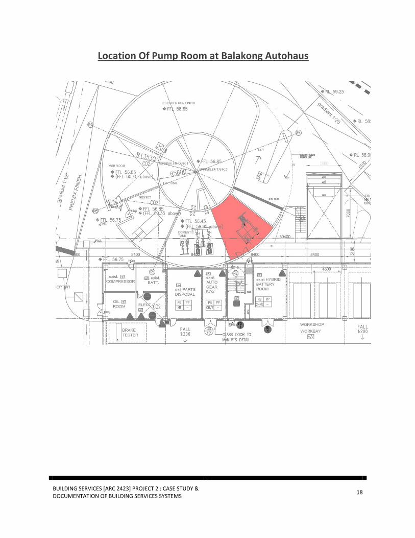
1.3.4 Duty Pump
Duty pump are usually connected with fire sprinkler because duty pump use electrical motor to deliver the water to the sprinkler system. The efficiency of pump is determined by the Flow Rate and the Total Head at the respective pump speed
Cross section of Duty Pump Process of a Duty Pump
Source :
http://www.enviropumpandseal.com/index.php?option=com_conten
t&view=article&id=57&Itemid=60
Source : http://www.fao.org/docrep/010/ah810e/ah810e07.htm
BUILDING SERVICES [ARC 2423] PROJECT 2 : CASE STUDY & DOCUMENTATION OF BUILDING SERVICES SYSTEMS
18
Location Of Pump Room at Balakong Autohaus

BUILDING SERVICES [ARC 2423] PROJECT 2 : CASE STUDY & DOCUMENTATION OF BUILDING SERVICES SYSTEMS
19
1.3.5 Smoke Detector
UBBL – SECTION 255.(1)
Every building shall be provided with means of detecting and extinguisher fire and alarms together with illuminated exits sign in accordance with the requirements as specified in the Tenth Schedule to these By-Laws.
Smoke detector in Balakong Autohaus
A smoke detector helps to warn people of possible fire. Smoke detector are use to detect smoke and giving a warning, usually a very loud beeping sound. Smoke detector usually found attaching to the ceiling and they are about the size of a hand. They detect fire in early stage and give you precious minutes that enable you to leave the building safely.
Hot gases are generated by fire and these gases rise because they are less dense than ordinary air. Smoke detector have large opening at the bottom as shown in the picture. A typical smoke detector has an infrared light beam that shoot across the chamber from a LED to a photocell. The light beam shoots constantly between the LED and the detector when there is no smoke so the alarm will remains silent. But when a fire breaks out, the beam is interrupted by the smoke that enters the chamber. When the light stop falling on the photocell, it will trigger the fire alarm in the building so alert the occupants.
Smoke Detector System
This diagram shows a typical smoke detector system to show how smoke detector works. The LED constantly shoot light beam to the photocell to show that no smoke were detected so the alarm remain silent. The light beam only get interrupted when smoke comes in to the chamber. When the photocell did not receive light beam, it will activate the alarm to alert the occupants that there might be potential fire around.
Typical smoke detector system
Souce : http://www.explainthatstuff.com/carbonmonoxidedetectors.html
BUILDING SERVICES [ARC 2423] PROJECT 2 : CASE STUDY & DOCUMENTATION OF BUILDING SERVICES SYSTEMS
20
1.3.6 Roller Shutter
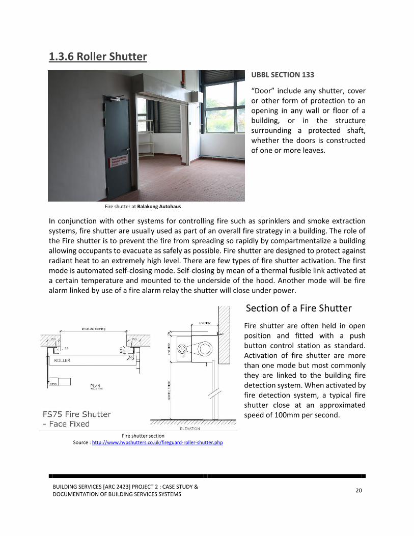
UBBL SECTION 133
“Door” include any shutter, cover or other form of protection to an opening in any wall or floor of a building, or in the structure surrounding a protected shaft, whether the doors is constructed of one or more leaves.
Fire shutter at Balakong Autohaus
In conjunction with other systems for controlling fire such as sprinklers and smoke extraction systems, fire shutter are usually used as part of an overall fire strategy in a building. The role of the Fire shutter is to prevent the fire from spreading so rapidly by compartmentalize a building allowing occupants to evacuate as safely as possible. Fire shutter are designed to protect against radiant heat to an extremely high level. There are few types of fire shutter activation. The first mode is automated self-closing mode. Self-closing by mean of a thermal fusible link activated at a certain temperature and mounted to the underside of the hood. Another mode will be fire alarm linked by use of a fire alarm relay the shutter will close under power.
Section of a Fire Shutter
Fire shutter are often held in open position and fitted with a push button control station as standard. Activation of fire shutter are more than one mode but most commonly they are linked to the building fire detection system. When activated by fire detection system, a typical fire shutter close at an approximated speed of 100mm per second.
Fire shutter section
Source : http://www.hvpshutters.co.uk/fireguard-roller-shutter.php

BUILDING SERVICES [ARC 2423] PROJECT 2 : CASE STUDY & DOCUMENTATION OF BUILDING SERVICES SYSTEMS
21
Location of Fire Shutter System

BUILDING SERVICES [ARC 2423] PROJECT 2 : CASE STUDY & DOCUMENTATION OF BUILDING SERVICES SYSTEMS
22
1.4 Passive Fire Protection System
1.4.1 Fire Wall
Fire wall/ fire-rated wall, is a type of wall that commonly used as a fireproof barrier. It has more
heat resistance than normal wall. It is built to slow down fire spreading from one space to another
space during fire emergency and act as a barrier to give enough time for occupants to escape
from the building. Besides, wall in car service and maintenance area are also constructed by using
fire walls as the content of the room is combustible and cause of fire.
Services and maintenance area. Fire wall indicated in red color.
Type of walls found on site: 100mm thick light weight block with 2 hours fire rates
Area covered: Separation of show room area and maintenance area.

BUILDING SERVICES [ARC 2423] PROJECT 2 : CASE STUDY & DOCUMENTATION OF BUILDING SERVICES SYSTEMS
23
Laws and regulations:
UBBL – section 198 (C)
Any wall or floor separating part of a building from any other part of the same building, which is
used or intended to be used mainly for a purpose failing within a different purpose group as, set
out in the fifth schedule to these by laws
UBBL – section 148 (6)
Any compartment wall or compartment floor which is required by these By-Laws to have FRP of
one hour or more shall be constructed wholly of non-combustible materials and, apart from any
ceiling, the required FRP of the wall or floor shall be obtained without assistance from non-
combustible.

BUILDING SERVICES [ARC 2423] PROJECT 2 : CASE STUDY & DOCUMENTATION OF BUILDING SERVICES SYSTEMS
24
1.4.2 Fire Rated Door
A fire resistant door is defined as door or shutter fitted into a door opening that is constructed
with fire proofing materials in order to prevent and restrict the transaction of heat for the longest
period of time possible protecting the occupants from smoke and fire.
Fire rated door Fire rated door section
Fire rated door found on site: Single leaf 1 HR fire rated door with metal framing
Materials used: Fire rated door consist two types of materials, wood and chock with fire resistant
paint as a finishing layer.
Thickness: 60mm thick (20mm thick layer of wood on both side of the door, 20mm layer of chock
in the center of the door)
Uses: Serves as compartmentalization of building entrances or exits in order to prevent fire and
smoke from spreading. In this building, 2 hours fire-rated door were installed at every fire
staircase entrances.

BUILDING SERVICES [ARC 2423] PROJECT 2 : CASE STUDY & DOCUMENTATION OF BUILDING SERVICES SYSTEMS
25
Law and Regulation:
UBBL-Section 162 (1)
- Fire doors of the appropriate FRP shall be provided
- Openings in compartment walls and separating wall shall be protected by a fire door
having a FRP in accordance with the requirements for that wall specified in the Ninth
Schedule to these By-Laws
UBBL-Section 164 (1)
- All fire doors shall be fitted with automatic door closers of the hydraulically spring
operated type in the case of swing doors and wire rope and weight type in the case of
sliding door.

BUILDING SERVICES [ARC 2423] PROJECT 2 : CASE STUDY & DOCUMENTATION OF BUILDING SERVICES SYSTEMS
26
1.4.3 Smoke Curtain
Smoke curtain/Fire curtain is a fabric panel that made of non-combustible material. It is used to
prevent fire and smoke from spreading to other part of the building.
Smoke curtain installed in the ceiling of show room area.
Smoke curtain can be found at the ceiling of the showroom corridor. The smoke curtain can be
activated by smoke cause by fire. When the curtain is activated, it can be control with either high
speed or low speed which depend to the fire situation.
Laws and regulation:
UBBL – section 161 (1)
- Any fire stop required by the provision of this part shall be formed and repositioned as to
prevent or retard the passage of flame.

BUILDING SERVICES [ARC 2423] PROJECT 2 : CASE STUDY & DOCUMENTATION OF BUILDING SERVICES SYSTEMS
27
1.4.4 Separation of Fire Risk Area
In this building, the fire risk area is designed effectively to separate the show room and car
maintenance area. Due to flammable gas and liquid that used for car services and maintenance,
the car services area is separated from the show room area by using fire proof compartment. In
case of fire, the services and maintenance area will be protected by compartment consist of roller
shutter and fire proofing wall, to avoid the fire and smoke from spreading to the lobby and show
room area.
Laws and regulations:
UBBL – section 139
The following area uses shall be separated from the other areas of the occupancy in which they
are located by fire resisting construction of elements of structure of a FRP to be determined by
local authority based on the hazard:
- Boiler rooms and associated duels storage room
- Laundries
- Repairs shops involving hazardous processes and materials
- Storage area of materials in quantities deemed hazardous
- Liquefied petroleum gas storage areas
- Linen rooms
- Transformer rooms and substations
- Flammable liquid stores

BUILDING SERVICES [ARC 2423] PROJECT 2 : CASE STUDY & DOCUMENTATION OF BUILDING SERVICES SYSTEMS
28
1.4.5 Emergency Exit Signage
Emergency exit signage found on site
Emergency exit signage are normally installed with green neon light and electrical supply backup
to ensure it can be use when the electrical supply has been cut off due to fire. It is located at the
top of every fire exit door. It provide direction for the occupants with clear and big letters.
Besides, the signs are lit 24/7 in case of emergencies.
UBBL- section 172
- Storey exits and access to such exits shall be marked by readily visible signs and shall not
be obscured by any decorations, furnishings or other equipment.
- A sign reading “KELUAR” with an arrow indicating the direction shall be placed in every
location where the direction of travel to reach the nearest exit is not immediately
apparent.
- Every exit sign shall have the word “KELUAR” in plainly legible letters not less than 150mm
high with the principal strokes of the letters not less than 18mm wide.
- All exist signs shall be illuminated continuously during periods of occupancy.
BUILDING SERVICES [ARC 2423] PROJECT 2 : CASE STUDY & DOCUMENTATION OF BUILDING SERVICES SYSTEMS
29
1.4.6 Fire Resistant Escape Stairs
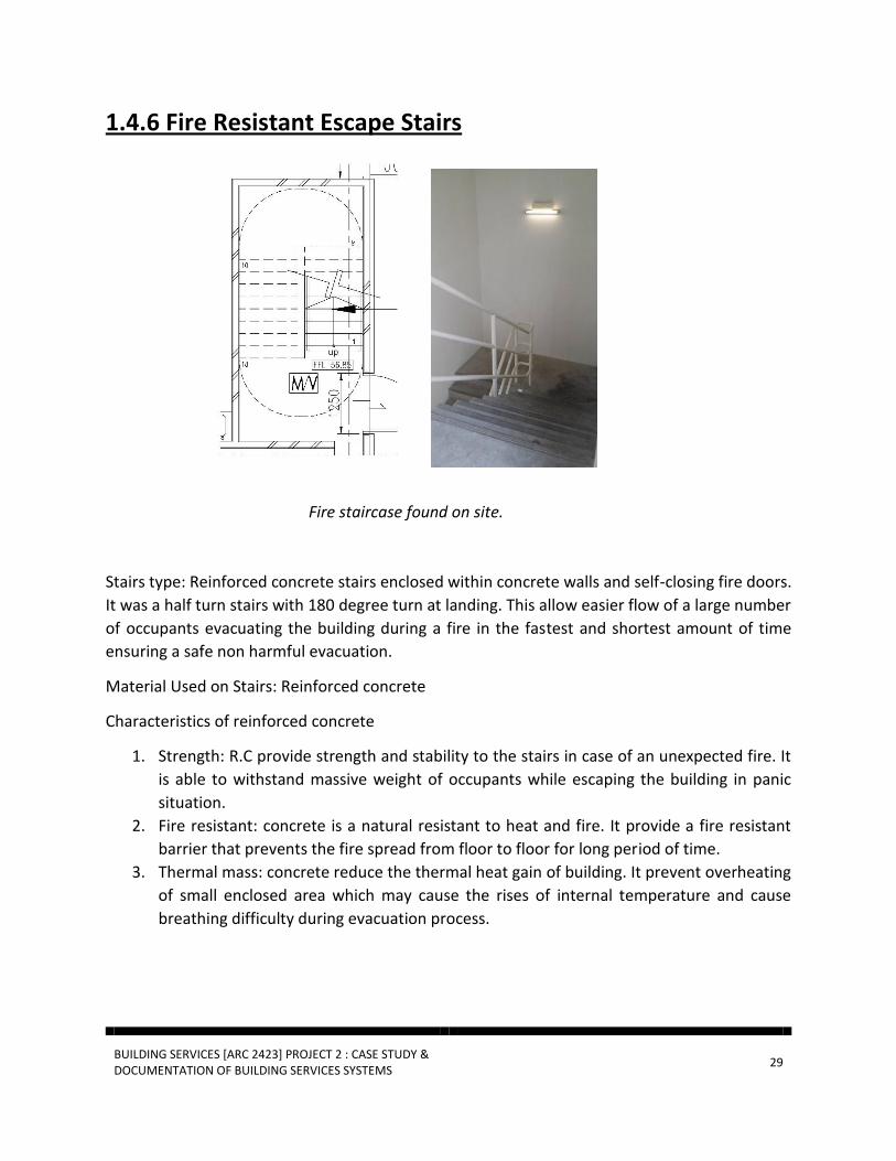
Fire staircase found on site.
Stairs type: Reinforced concrete stairs enclosed within concrete walls and self-closing fire doors.
It was a half turn stairs with 180 degree turn at landing. This allow easier flow of a large number
of occupants evacuating the building during a fire in the fastest and shortest amount of time
ensuring a safe non harmful evacuation.
Material Used on Stairs: Reinforced concrete
Characteristics of reinforced concrete
1. Strength: R.C provide strength and stability to the stairs in case of an unexpected fire. It
is able to withstand massive weight of occupants while escaping the building in panic
situation.
2. Fire resistant: concrete is a natural resistant to heat and fire. It provide a fire resistant
barrier that prevents the fire spread from floor to floor for long period of time.
3. Thermal mass: concrete reduce the thermal heat gain of building. It prevent overheating
of small enclosed area which may cause the rises of internal temperature and cause
breathing difficulty during evacuation process.
BUILDING SERVICES [ARC 2423] PROJECT 2 : CASE STUDY & DOCUMENTATION OF BUILDING SERVICES SYSTEMS
30
Locations: the building is five floors high, there are four fire escape stairs on each floor of the
building, located at the left and right side of the building. It provide easy accessibly from any
location in the building.
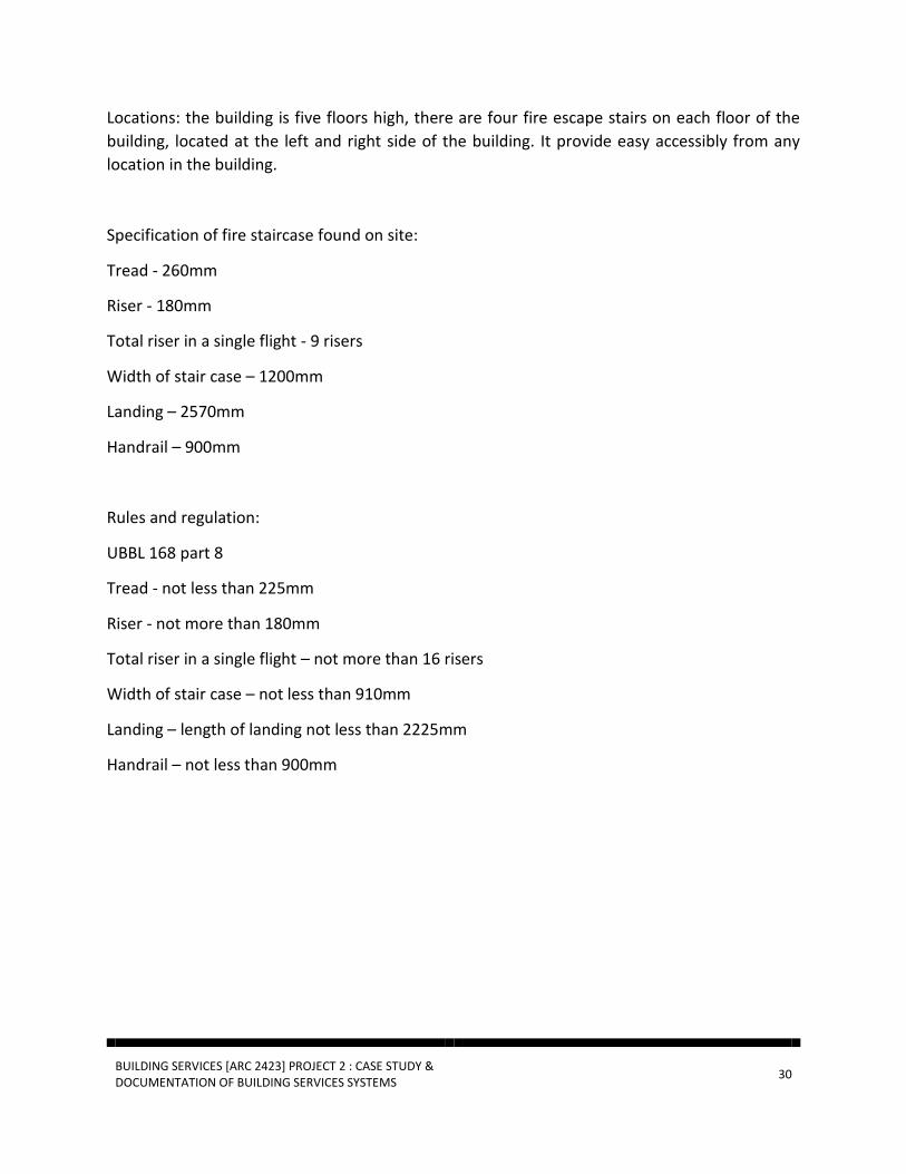
Specification of fire staircase found on site:
Tread - 260mm
Riser - 180mm
Total riser in a single flight - 9 risers
Width of stair case – 1200mm
Landing – 2570mm
Handrail – 900mm
Rules and regulation:
UBBL 168 part 8
Tread - not less than 225mm
Riser - not more than 180mm
Total riser in a single flight – not more than 16 risers
Width of stair case – not less than 910mm
Landing – length of landing not less than 2225mm
Handrail – not less than 900mm

BUILDING SERVICES [ARC 2423] PROJECT 2 : CASE STUDY & DOCUMENTATION OF BUILDING SERVICES SYSTEMS
31
1.5 Conclusion Active Fire Protection System From the research and analysis, active and passive fire protection plays important role in protecting a building and occupants. Since Balakong Autohaus is only a Mercedes Showroom, it do not have so much system compared to Malls or other bigger building. But, the fire protection steps in Balakong Autohaus has clearly complies with the UBBL and each area are fully equip with fire protection system. They predicted which area to be more potential fire breakout and secure it with better fire protection system. They also update their appliances with the requirement that are given by the Bomba and also to ensure their worker safety. Without doubt, every area was perfectly covered with fire protection system and there is no further recommendation that I could suggest for Balakong Autohaus.
Passive Fire Protection System Fire wall
From the placement of the wall, it can effectively protect the occupants from emergency fire. The
walls is designed to last for 2hours when contact with fire. It has enough time for the evacuation
to carry on.
Fire Rated Door
From the quantities and placing of fire doors, it fulfilled the requirement from the local authorities.
The fire door effectively prevent the fire from entering to the emergency staircase. Besides that,
automatic door closers were installed in every fire rated door to ensure the door is always closed.
Smoke Curtain
The placement of the smoke curtain is suitable for this building type. When the fire happen, it help
to block the smoke so that the occupant can quickly escape the building through the showroom
corridor.
Separation of Fire Risk Area
The architect had done well in separation of fire risk area. It successfully prevent fire that cause
in services and maintenance area from separating to the show room area.
BUILDING SERVICES [ARC 2423] PROJECT 2 : CASE STUDY & DOCUMENTATION OF BUILDING SERVICES SYSTEMS
32
Emergency Exit Signage
In this building, the exit signage can be found at the top of every fire exit door. The sign are also
lit 24/7 and the size of the signage is fulfilled the local authorities standard.
Fire Resistant Escape Stairs
Lasly, The fire staircase found on site has met the requirement of local authority’s standard.
BUILDING SERVICES [ARC 2423] PROJECT 2 : CASE STUDY & DOCUMENTATION OF BUILDING SERVICES SYSTEMS
33
2.0 AIR CONDITIONING SYSTEM
2.1 Introduction
This research paper covers the system of the air conditioning adopted by the chosen building,
Hap Seng Star Sdn Bhd, Balakong Autohaus. This is for us to learn and acquire an in-depth
knowledge on how thermal comfort and improved indoor air quality can be achieved.
The purpose of an air conditioning is to help create a comfortable indoor environment, by
allowing air to be circulated throughout the building and expelling stale air, purifying it. It also
helps and improves the ventilation inside the building by controlling the temperature of each
area into a suitable degree as well as dehumidifying the air-conditioned area.
The Hap Seng Star Sdn Bhd, Balakong Autohaus is a multi-story car showroom that requires the
aid of mechanical cooling to distribute fresh cool air. The topics that are covered in this research
paper are as follows:
- VRV/VRF (Variable Refregerant Flow) air conditioning system
- Basic Refrigeration Cycle
- Components of the air conditioning units

BUILDING SERVICES [ARC 2423] PROJECT 2 : CASE STUDY & DOCUMENTATION OF BUILDING SERVICES SYSTEMS
34
2.2 Literature Review Air conditioning is the simultaneous mechanical control over temperature, humidity and air
motion. One of the most important components of the system is the air-distribution. The
processes of the components involve achieving a suitable level of temperature, humidity,
cleanliness and air motion in an occupied zone of the conditioned area. All of this is done in a
manner whereby the occupants would not feel any draft. (Ananthanarayanan, 2013)
The purpose of an air conditioning system is to improve indoor air quality and provides human
thermal comfort. These can be attained not only by controlling the level of the temperature, but
also the combination of the temperature of relative humidity and air movement around the
room. The central/package air conditioners are usually for a large area. It consists of a cycle where
the conditioned air is distributed throughout the area and the air that has picked up moisture
and heat will be returned to the air conditioning apparatus for cooling.
Another type of an air conditioning system is the centralized system. Central air conditioners
have a centralized duct system, which has an air handler, air supply system, air return duct and
the grilles and register, which circulates warm air from a furnace or cooled air from central air
conditioning to our room. It then returns the air back to the system and starts again. (Central-air
conditioner and refrigeration.com, 2014)
A small sized rooms or houses require a room/split system air conditioner. A split system consists
of two parts, the outdoor unit that houses the compressor, condenser and expansion valve and
the indoor unit, which houses the evaporator or cooling coil and cooling fan. In small sized
commercial or office buildings, the multi split system were usually used instead. It is similar to
the split system but with an ability to connect a single outdoor unit via refrigerant grade piping
to multiple indoor units, which can be mounted in a number of rooms throughout the building.

BUILDING SERVICES [ARC 2423] PROJECT 2 : CASE STUDY & DOCUMENTATION OF BUILDING SERVICES SYSTEMS
35
2.3 Finding and Analysis
2.3.1 VRV / VRF (Variable refrigerant flow) air conditioning
system
Hap Seng Realty Mercedes Benz Bakalong is separated into two compartment, a show room and
a workshop. The air conditioning system are mainly used in the showroom compartment. VRV
(Variable refrigerant volume) system is adopted in showroom compartment. Unlike the
traditional split unit that used one to one split system, VRV air conditioning are able to provide
total versatility and each indoor unit may cool / heat independently of each other.
Figure 3.1: Diagram of VRV system work. (Indiamart.com)
In this case the heat extracted from zones requiring cooling is put to use in the zones requiring
heating. This is made possible because the heating unit is functioning as a condenser, providing
sub-cooled liquid back into the line that is being used for cooling. With this VRV air conditioning
system, it greatly help Hap Seng Realty Mercedes Benz showroom to achieve thermal comfort,
meanwhile also promote the idea of energy saving.

BUILDING SERVICES [ARC 2423] PROJECT 2 : CASE STUDY & DOCUMENTATION OF BUILDING SERVICES SYSTEMS
36
2.3.2 Basic Refrigeration Cycle
VRV air conditioning use refrigerant as the cooling medium rather than chilled water, and this
allow VRV air conditioning system cooling particular zone while heating, removing heat or stop
functioning at other zone. As for Economy purpose, all air conditioners use the same cycle of
compression, condensation, expansion, and evaporation in a closed circuit.
These are few principle of refrigeration.
Liquids absorb heat when changed from liquid to gas
Gases give off heat when changed from gas to liquid
Figure 3.2 : Basic
Refrigeration cycle
(Source : https://www.swtc.
edu/ag _power/air_conditioning/
lecture/basic_cycle.htm
The refrigerant comes into the compressor as a low-pressure gas, it is compressed and
then moves out of the compressor as a high-pressure gas.
The gas then flows to the condenser. Here the gas condenses to a liquid, and gives off its
heat to the outside air.
The liquid then moves to the expansion valve under high pressure. This valve restricts the
flow of the fluid, and lowers its pressure as it leaves the expansion valve.
The low-pressure liquid then moves to the evaporator, where heat from the inside air is
absorbed and changes it from a liquid to a gas.
As a hot low-pressure gas, the refrigerant moves to the compressor where the entire cycle
is repeated.
BUILDING SERVICES [ARC 2423] PROJECT 2 : CASE STUDY & DOCUMENTATION OF BUILDING SERVICES SYSTEMS
37
2.4 Components
2.4.1 Outdoor units
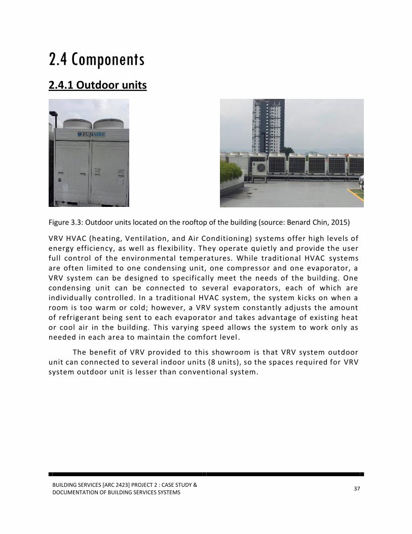
Figure 3.3: Outdoor units located on the rooftop of the building (source: Benard Chin, 2015)
VRV HVAC (heating, Ventilation, and Air Conditioning) systems offer high levels of energy efficiency, as well as flexibility . They operate quietly and provide the user full control of the environmental temperatures. While traditional HVAC systems are often limited to one condensing unit, one compressor and one evaporator, a VRV system can be designed to specifically meet the needs of the building. One condensing unit can be connected to several evaporators, each of which are individually controlled. In a traditional HVAC system, the system kicks on when a room is too warm or cold; however, a VRV system constantly adjusts the amount of refrigerant being sent to each evaporator and takes advantage of existing heat or cool air in the building. This varying speed allows the system to work only as needed in each area to maintain the comfort level .
The benefit of VRV provided to this showroom is that VRV system outdoor unit can connected to several indoor units (8 units), so the spaces required for VRV system outdoor unit is lesser than conventional system.

BUILDING SERVICES [ARC 2423] PROJECT 2 : CASE STUDY & DOCUMENTATION OF BUILDING SERVICES SYSTEMS
38
Figure 3.4 : A diagram showing how VRV outdoor unit is connected to the indoor unit ( Source :
http://www.masonbarry.com/VRV )
Most of the indoor unit in Hap Seng Mercedes Benz showroom is connected to VRV Outdoor unit.
Due to the economy purpose, some of the office are using Room Air-Conditioner system.
Figure 3.5 : Outdoor unit for Room Air-Conditioner system.

BUILDING SERVICES [ARC 2423] PROJECT 2 : CASE STUDY & DOCUMENTATION OF BUILDING SERVICES SYSTEMS
39
2.4.2 Indoor units
The Indoor units used in Hap Seng Mercedes Benz showroom is ceiling mounted cassette type.
The benefits of this kind of indoor units given to Hap send Mercedes Benz showroom is that, the
slim design enables flexible installation to narrow ceiling and also it can hide above ceiling to
create a clean and neat ceiling look and this fits the requirement to achieve a high-end
showroom.
Figure 3.6: Indoor unit used in Hap Seng Showroom (Source : Benard Chin, 2014)
Figure 3.7: A diagram of how a ceiling mounted cassette type work
This ceiling mounted cassette type extract heat from one zone and providing other zone that
need cooling, this greatly help achieving energy saving in such a big showroom.

BUILDING SERVICES [ARC 2423] PROJECT 2 : CASE STUDY & DOCUMENTATION OF BUILDING SERVICES SYSTEMS
40
2.5 Conclusion
The market of the VRV/VRF air conditioning system is rapidly increasing in the modern world as
it provides with a lot of advantages:
• Simultaneous heating and cooling between zones or known as ‘total heat recovery,’ this effectively allows us to redirect heat in a building to where it is needed.
• Double heat recovery between zones using the refrigerant circuit and between refrigerant systems, using the ambient loop. This allows us to further optimize energy savings.
• Smaller and lighter than comparable rooftop systems or chillers of similar tonnage enabling easier installation and avoiding the need for a dedicated mechanical room.
• Capital cost savings from space savings. • Design flexibility due to the ability to use a variety of indoor units of different capacity and
design. • Modular design enables phased conditioning of the building as different areas become
occupied during construction or renovation and easily adapts to changes in room layouts. • High coefficient of performance (COP) meaning the system is very efficient. For every 1kW of
electrical power used by the system, generally 4- 5kW of heating/cooling are provided to the occupants. COP can reach 8 – 10 in heat recovery mode.
• Long pipe runs when compared to other refrigerant based heat pump’s allowing for greater flexibility in design.
• Available in both water or air source configurations to suit specific applications. • Quiet operation compared to conventional heat pump systems as the compressor pump for
VRF is typically located outside the space being conditioned. There is very little, if any discernible noise other air velocity from a fractional HP fan through discrete grills.
However, there are several disadvantages that need to be reconsidered. Costs will depend on
application but are currently generally equitably to older, less efficient technology. As this leading
edge technology is adopted into the industry, VRF will become even more cost effective over
traditional systems. Reliability. VRF systems are modular (typically one ‘system’ per floor)
compared with central plant systems. This means that if a system were to fail, only one floor
would normally be affected. As VRF systems are small packaged systems they can be readily
repaired. If a chiller plant fails, typically the entire building is affected and repairs are usually
more complicated. Compared with Heat pump systems, one VRF condensing unit can serve up to
50 Fan Coils. Heat Pumps utilize a compressor in each unit, potentially increasing serviceability
requirements, especially when equipment reaches typical life expectancy. Leaks are highly
unlikely to be a problem with a professionally installed VRF system, and no more likely than any
other refrigerant based system. However, if one were to occur, VRF systems use a relatively small
amount of refrigerant compared to other systems.

BUILDING SERVICES [ARC 2423] PROJECT 2 : CASE STUDY & DOCUMENTATION OF BUILDING SERVICES SYSTEMS
41
3.0 MECHANICAL VENTILATION
SYSTEM
3.1 Introduction
Air Exhaust / Ventilation Fan Applications in Hazardous Location Use Hazardous location air exhaust / ventilation fan (sometimes called explosion proof) may be required in any area where the presence of flammable gases, vapors or finely pulverized dust in the atmosphere is sufficient to create a threat of an explosion or fire. It may also be required where easily ignitable fibers or flying's are present. The following information is a representative, but is not an all-inclusive, list of the types of locations and operations that require hazardous location air exhaust / ventilation equipment in at least certain areas.
BUILDING SERVICES [ARC 2423] PROJECT 2 : CASE STUDY & DOCUMENTATION OF BUILDING SERVICES SYSTEMS
42
3.2 Literature Review
In commercial developments, mechanical ventilation is typically driven by air handling units (AHU) connected to ductwork within the building that supplies air to and extracts air from the interior. Typically they comprise an insulated box that forms the housing for; filter racks or chambers, a fan (or blower), and sometimes heating elements, cooling elements, sound attenuators and dampers. In some situations, such as in swimming pools, air handling units might include dehumidification. The design of mechanical ventilation systems is generally a specialist task, undertaken by a building services engineering. Whilst there are standards and rules of thumb that can be used to determine air flow rates for straight-forward situations, when mechanical ventilation is combined with heating, cooling, humidity control and the interaction with natural ventilation, thermal mass and solar gain, the situation can quickly become very complicated. This, along with additional complications, such as the noise generated by fans, and the impact of ductwork on acoustic separation means it is vital building service are considered at the outset of the building design process, and not seen as an add-on.

BUILDING SERVICES [ARC 2423] PROJECT 2 : CASE STUDY & DOCUMENTATION OF BUILDING SERVICES SYSTEMS
43
3.3 Air Handling Unit (AHU)
FIGURE 4.1: AHU ROOFTOP OUTPUT
Air handling unit [AHU] air handler, or air handling unit (often called an AHU), is used to condition and circulate air as part of an HVAC system. An air handler usually contains a blower, heating or cooling elements, filter racks or chambers, sound attenuators, and dampers. Air handlers usually connect to ductwork that distribute the conditioned air through the building and return it to the AHU. Small air handlers are called terminal units, and may only include an air filter, coil, and blower. These smaller units are also called blower coils or fan coil units. A larger air handler that conditions 100% outside air, and no re-circulated air, is known as a makeup air unit (MAU). An air handler designed for outdoor use, typically on roofs, is known as a rooftop unit (RTU).
BUILDING SERVICES [ARC 2423] PROJECT 2 : CASE STUDY & DOCUMENTATION OF BUILDING SERVICES SYSTEMS
44
3.4 Industrial Circular Fan
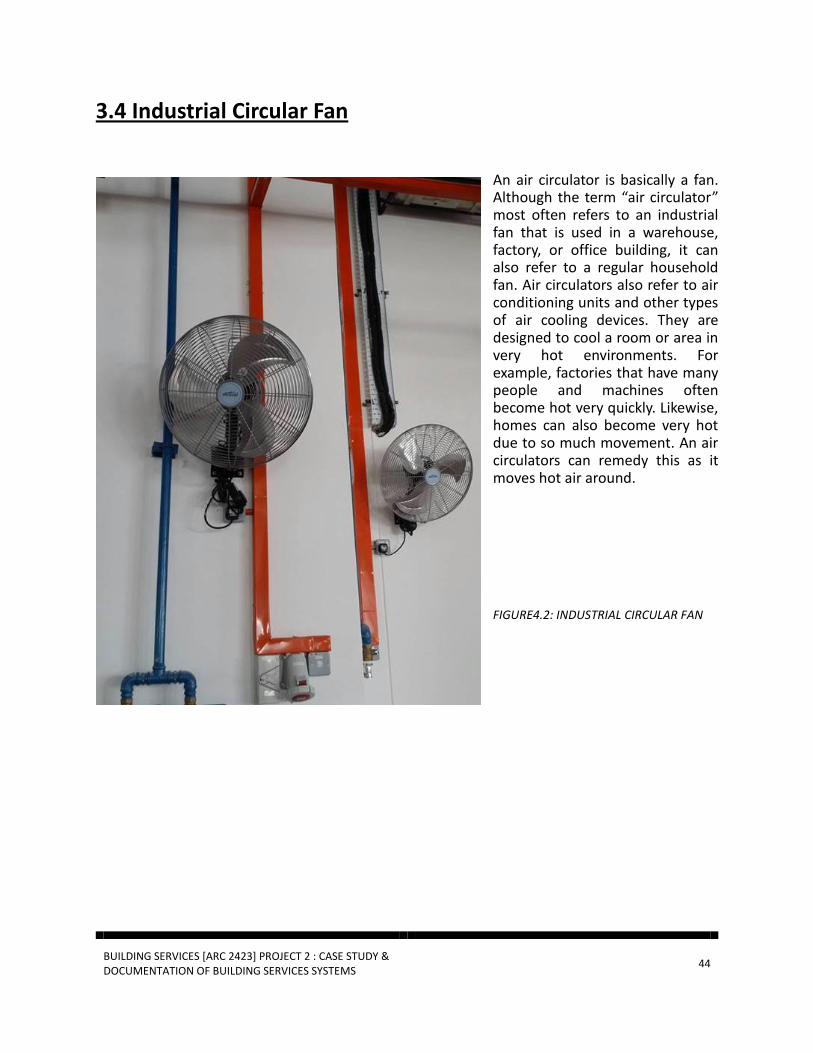
An air circulator is basically a fan. Although the term “air circulator” most often refers to an industrial fan that is used in a warehouse, factory, or office building, it can also refer to a regular household fan. Air circulators also refer to air conditioning units and other types of air cooling devices. They are designed to cool a room or area in very hot environments. For example, factories that have many people and machines often become hot very quickly. Likewise, homes can also become very hot due to so much movement. An air circulators can remedy this as it moves hot air around.
FIGURE4.2: INDUSTRIAL CIRCULAR FAN

BUILDING SERVICES [ARC 2423] PROJECT 2 : CASE STUDY & DOCUMENTATION OF BUILDING SERVICES SYSTEMS
45
3.5 Air Duct System
FIGURE4.3: DUCT SYSTEM
The duct, or air distribution, system used in cooling and heating your home is a collection of tubes that
distributes the heated or cooled air to the different rooms. This branching network of rectangular tubes—
usually constructed of sheet metal, fiberglass board, or a flexible plastic-and-wire composite. The duct
system is designed to supply rooms with air that is “conditioned"—that is, heated or cooled by the
heating, ventilation, and air conditioning (HVAC) equipment—and to circulate or return the same volume
of air back to the HVAC equipment.
Typical air-duct systems lose 25 to 40% of the heating or cooling energy put out by the cooling and heating system. Leaks, one way in which conditioned air is lost in the duct system, make the HVAC system work harder, thus increasing your utility bill. In addition, duct leakage can lessen comfort and endanger your health and safety. Your duct system has two main air-transfer systems—supply and return. The supply side delivers the conditioned air to the home through individual room registers—what you feel blowing out of the registers. The return side withdraws inside air and delivers it to the air handler of your central system. All of the air drawn into the return duct(s) is conditioned and should be delivered back through the supply register.

BUILDING SERVICES [ARC 2423] PROJECT 2 : CASE STUDY & DOCUMENTATION OF BUILDING SERVICES SYSTEMS
46
3.5.1 Single Duct System
FIGURE4.4: SINGLE DUCT SYSTEM
FIGURE4.5: VAV SYSTEM
Usually the air volumes required to cool a space greatly exceed that required for ventilation. It is usual therefore to employ a mixing box, usually part of the AHU, equipped with a set of modulating dampers which can recirculate varying amounts of outside air in mid-season to take advantage of “free cooling”.

BUILDING SERVICES [ARC 2423] PROJECT 2 : CASE STUDY & DOCUMENTATION OF BUILDING SERVICES SYSTEMS
47
3.5.2 Double Duct System
FIGURE4.6: DOUBLE DUCT SYSTEM
FIGURE4.7: VAV SYSTEM
Dual duct systems distribute air through two ducts, one hot and the other cold, and the air is mixed in a "mixing box" in each zone to give the required supply temperature. These systems are very flexible and effective in dealing with a wide range of sensible loads. However the systems are expensive in terms of both equipment and duct distribution space because of the need for two supply ducts. This usually results in high velocity distribution to reduce the space requirements which in turn has a penalty in higher power requirements for the high pressure fans.

BUILDING SERVICES [ARC 2423] PROJECT 2 : CASE STUDY & DOCUMENTATION OF BUILDING SERVICES SYSTEMS
48
3.6 Exhaust Ventilation
FIGURE4.6: EXHAUSTED FAN (OUTPUT) FOR HARMFUL GAS
FIGURE4.6: EXHAUSTED FAN (OUTPUT) LOCATED ON THE ROOF TOP

BUILDING SERVICES [ARC 2423] PROJECT 2 : CASE STUDY & DOCUMENTATION OF BUILDING SERVICES SYSTEMS
49
3.7 Conclusion According to the UBBL requirement and regulation (UBBL 2012, amendments on EE and MS 1525), each mechanical ventilation system (supply and/ or exhaust) shall be equipped with readily accessible switch or the means for shut-off or volume reduction when ventilation is required.
In the AHU room, there is control switch box which proved the UBBL requirement mentioned before has been applied to Balakong Autohaus Mercedes showroom. According to MS1525 year 2007, ACMV system should be equipped with automatic controls capable of Accomplishing a reduction of energy use for example through equipment shutdown during periods of non – users or alternative use of the spaces served by the system.
Since Balakong Autohaus is a showroom, it is schedule to be open during working days and working hours only with the exception of any events being held there. In conclusion, the system used for Balakog Autohaus is appreciate to the building size and purposes. The components are all placed at an appropriate location, well- maintained and taken care of. Every mechanical components are also adequate for a building of that scale.
BUILDING SERVICES [ARC 2423] PROJECT 2 : CASE STUDY & DOCUMENTATION OF BUILDING SERVICES SYSTEMS
50
4.0 MECHANICAL TRANSPORTATION SYSTEM
4.1 Introduction
The research of mechanical transportation system will be within Hap Seng Star Sdn Bhd,
Mercedes Balakong Autohaus. The case study will be compiled base on details of the mechanical
transportation at Mercedes Balakong Autohaus. The referencing will be conformance to UBBL-
Mechanical Transportation system as requirements. Mercedes Balakong Autohaus is a
showroom & workshop, hence the building a 3 storey high while the lifts we’re there for
convenient usage for passengers to travel between levels to levels in the building.
Literature review will be explaining some typical mechanical transportation and elaborates on
the type of mechanical transportation. This research will concludes an analysis and
recommendations for improvements to the mechanical transportation system in Mercedes
Balakong Autohaus. Installing lift systems allows more mobility and accessibility which are greatly
expanded, somehow it also allow for more efficient and comfortable workspace.
A design of an architect also includes the design space of a lift waiting area. The lift waiting area
requires certain area for passengers to wait for the lift to ride on. In the case study of Mercedes
Balakong Autohaus lifts, The lifts in the showroom & workshop is meant for disables usage,
convenient movement to each floor & also goods transportation only. The maintenance cost for
each lift to service wouldn’t take up much time because there’s only 2 units and it well organized
for it current placed locations.
The maintenance for lift system must be in diligent and thorough. Each and every components
must be kept in top conditions, it’s to ensure the safety and comfort of the passengers while
utilizing the lift. Lift system also must be built and implemented into the building according with
the Uniform Building By-Laws ( UBBL ) to ensure safety usage and standardization of mechanical
of the lift system.

BUILDING SERVICES [ARC 2423] PROJECT 2 : CASE STUDY & DOCUMENTATION OF BUILDING SERVICES SYSTEMS
51
4.2 Literature Review
The Hap Seng Star Sdn Bhd, Mercedes Balakong Autohaus is a showroom & workshop building of
3 floors. As this building is divided into 2 sections. Section 1, which is the showroom will have 1
lift for their customers to excess floors easier. Section 2, the lift will be a service lift for
transporting vehicle to specific levels of the workshop. The two sections is classified as passenger
lift and service lift.
The lift are to ease the transportation of passengers and goods ( lift cars up to 1,000kg ). With
the technologies they have today, working / moving each of the goods will be so much convenient
and safer in the present days today.
According to Uniform Building By-Laws ( UBBL ), Under Section 124, Lifts.
‘’For all non-residential buildings exceeding four storeys above or below the main access level
at least one lift shall be provided.’’
According to Act 139 Factories and Machinery act 1967, Under Section 12 Part II, Lifting of
weights
‘’ No person shall be employed to lift, carry or move any load so heavy as to be likely to cause
bodily injury to him.’’
Which this will ensure the comfort and usage for passenger towards the lifts and also increases
the efficiency to access between floors.

BUILDING SERVICES [ARC 2423] PROJECT 2 : CASE STUDY & DOCUMENTATION OF BUILDING SERVICES SYSTEMS
52
According to Uniform Building By-Laws ( UBBL ), Under Section 153, Smoke detectors for lift
lobbies.
(1) ‘’All lift lobbies shall be provided with smoke detectors.’’
(2) ‘’Lift not opening into a smoke lobby shall not use door reopening devices controlled by
light beam or photo-detectors unless incorporated with a force close feature which after
thirty seconds of any interruption of the beam causes the door to close within a preset
time.’’
By-Law Section 153, smoke detectors for lift lobbies shows that every lift must have a fire alarm
system inside. It’s because of in case of an emergency. Most of the detectors are hidden inside
lifts, due to aesthetic purposes. This is to ensure total safety not just outside around the building
and it applies also inside a lift.
The location of the lifts in Mercedes Balakong Autohaus, is located as shown in Figure 4.2.0, as
highlight on the ground floor plan. First lift will be located near the entrance on the right side of
the Figure 4.2.0, which is highlighted in red. For the service lift, It’s located behind the workshop.
It’s indicated in green, left hand side of the Figure 4.2.0, on ground floor plan.
The lift indicated in red, approximately dimension is 4600mm x 5120mm. This usage is for
passenger access to floors including disables usage for this. The lift indicated in green,
approximately 5000mm x 7000mm. This is a service lift for delivery their cars to specialist
workshop levels. Hence these cars doesn’t need to spent much petrol going up ramps rather than
just use the lift.

BUILDING SERVICES [ARC 2423] PROJECT 2 : CASE STUDY & DOCUMENTATION OF BUILDING SERVICES SYSTEMS
53
Figure 4.2.0; Mercedes Balakong Autohaus, Ground Floor Plan, N.T.S. Indication location of lift
located in red is passenger lift which connects from Ground floor to Second floor, highlighted in
green is service lift which connects ground floor to roof floor for parking.
(Hap Seng Star Sdn Bhd, Mercedes Balakong Autohaus, 2015)

BUILDING SERVICES [ARC 2423] PROJECT 2 : CASE STUDY & DOCUMENTATION OF BUILDING SERVICES SYSTEMS
54
Figure 4.2.1; Mercedes Balakong Autohaus, Passenger Lift Plan Drawing. N.T. S
The lift is specifically just for passenger. Which is connected to 2 floors.
(Hap Seng Star Sdn Bhd, Mercedes Balakong Autohaus, 2015)

BUILDING SERVICES [ARC 2423] PROJECT 2 : CASE STUDY & DOCUMENTATION OF BUILDING SERVICES SYSTEMS
55
Figure 4.2.2; Mercedes Balakong Autohaus, Section, N.T.S . Indication location of lift located in
red is passenger lift which connects from Ground floor to Second floor
(Hap Seng Star Sdn Bhd, Mercedes Balakong Autohaus, 2015)
BUILDING SERVICES [ARC 2423] PROJECT 2 : CASE STUDY & DOCUMENTATION OF BUILDING SERVICES SYSTEMS
56
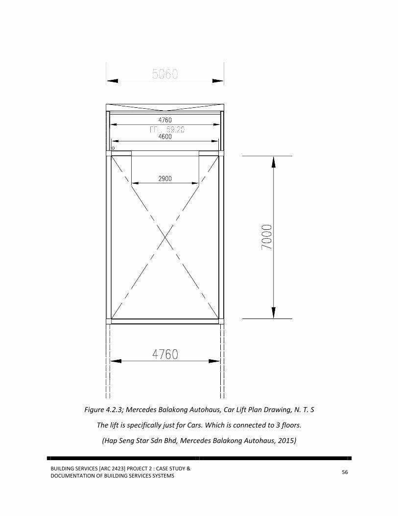
Figure 4.2.3; Mercedes Balakong Autohaus, Car Lift Plan Drawing, N. T. S
The lift is specifically just for Cars. Which is connected to 3 floors.
(Hap Seng Star Sdn Bhd, Mercedes Balakong Autohaus, 2015)

BUILDING SERVICES [ARC 2423] PROJECT 2 : CASE STUDY & DOCUMENTATION OF BUILDING SERVICES SYSTEMS
57
4.3 Operation Of Lift System
Mercedes Balakong Autohaus uses ‘’ Machine Rooms-Less (MRL) Lift ‘’ lift system. The lift is
connected to a computerized system. The system is also be monitored from the general control
room in the security room. ( As It’s private & confidential for the location, info’s of the control
room )
The control room control’s & observes each and every movement of the lift and footage of CCTV.
As the staff can monitor the control of lift from the control room. In case of fire situations, both
lift is installed with fire alarm detector system. If the alarm goes off, the control room will be
immediately notified. For safety reasons, if there’s a breakdown / issues for any of those 2 lifts,
the control room will also be notified immediately, regardless on which floor the control room
can see it clearly from there. Every lift is also installed with speaker system, this is for safety
reasons & emergency, just to communicate if there’s any issues / problems inside the lift, while
the person in charge / mechanic in charge will be notify and be called in for immediate repairing.

BUILDING SERVICES [ARC 2423] PROJECT 2 : CASE STUDY & DOCUMENTATION OF BUILDING SERVICES SYSTEMS
58
4.4 SYSTEM COMPONENTS
4.4.1 Lift System ( A ) Machine –Room Less Lift
-Passenger Lift, highlighted in red, Location in refer figure 4.2.0
The ‘’Machine-Room Less Lift’’ (MRL), are a type of traction lift which do not require a machine
room at the top of the hoistway. The MRL instead have the traction hoisting machine installed
either on the top side wall of the hoistway or on the bottom of the hoistway. While the hoisting
motor is installed on the hoistway side wall, the main controller is installed on the top floor next
to the landing doors. The controller is situated behind a locked cabinet which have to be unlocked
using a key for maintenance, repair or emergency purposes.
Figure 4.4.0 : Diagram showing the components of the lift system. As diagram is showing the lift
system of Machine-Room Less Lift (MRL) and also the placement of MRL machine, counter
weight and etc.
(Hap Seng Star Sdn Bhd, Mercedes Balakong Autohaus, 2015)
BUILDING SERVICES [ARC 2423] PROJECT 2 : CASE STUDY & DOCUMENTATION OF BUILDING SERVICES SYSTEMS
59
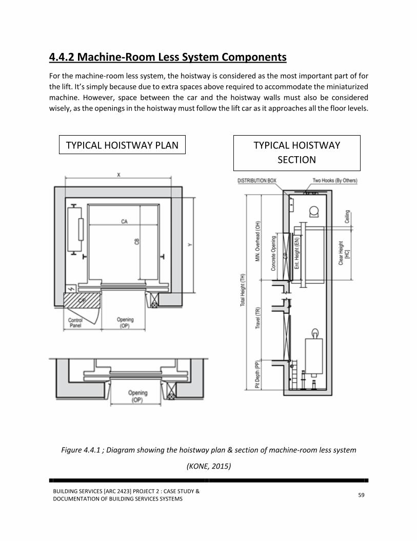
4.4.2 Machine-Room Less System Components
For the machine-room less system, the hoistway is considered as the most important part of for
the lift. It’s simply because due to extra spaces above required to accommodate the miniaturized
machine. However, space between the car and the hoistway walls must also be considered
wisely, as the openings in the hoistway must follow the lift car as it approaches all the floor levels.
Figure 4.4.1 ; Diagram showing the hoistway plan & section of machine-room less system
(KONE, 2015)
TYPICAL HOISTWAY PLAN TYPICAL HOISTWAY
SECTION
BUILDING SERVICES [ARC 2423] PROJECT 2 : CASE STUDY & DOCUMENTATION OF BUILDING SERVICES SYSTEMS
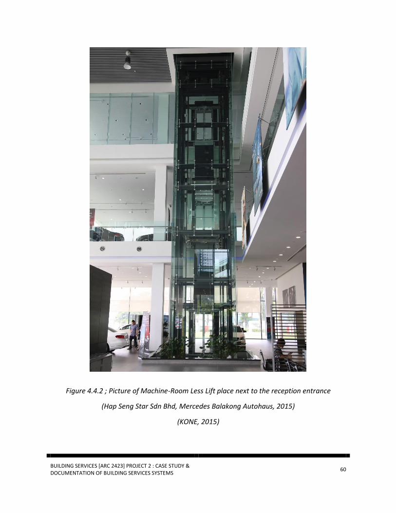
60
Figure 4.4.2 ; Picture of Machine-Room Less Lift place next to the reception entrance
(Hap Seng Star Sdn Bhd, Mercedes Balakong Autohaus, 2015)
(KONE, 2015)

BUILDING SERVICES [ARC 2423] PROJECT 2 : CASE STUDY & DOCUMENTATION OF BUILDING SERVICES SYSTEMS
61
Figure 4.4.2 ; Picture of Machine-Room Less Lift. Lift components as shown in pictures.
(Hap Seng Star Sdn Bhd, Mercedes Balakong Autohaus, 2015)
(KONE, 2015)

BUILDING SERVICES [ARC 2423] PROJECT 2 : CASE STUDY & DOCUMENTATION OF BUILDING SERVICES SYSTEMS
62
Figure 4.4.3 ; Picture of Machine-Room Less Lift. Lift components as shown in pictures.
Interior components &
(Hap Seng Star Sdn Bhd, Mercedes Balakong Autohaus, 2015)
(KONE, 2015)
According to Act 139 Factories and Machinery act 1967, Under Section 12 Part II, Lifting of
weights
‘’ No person shall be employed to lift, carry or move any load so heavy as to be likely to cause
bodily injury to him.’’

BUILDING SERVICES [ARC 2423] PROJECT 2 : CASE STUDY & DOCUMENTATION OF BUILDING SERVICES SYSTEMS
63
4.4.3 Lift System ( B ) Geared Traction Lift
-Car Lift, highlighted in green, Location in refer figure 4.2.0
The Geared Traction Lift, the electric motor in this design drives a gear-type reduction unit, which
turns the hoisting sheave. While slower than a typical gearless elevator, the gear reduction offers
the advantage of requiring a less powerful motor to turn the sheave. These elevators typically
operate at speeds from 350 to 500 feet per minute (1.7 to 2.5 meters per second) and carry loads
of up to 30,000 pounds (13,600 kgs)( which is applied in the building for lifting cars to certain
levels ). An electrically controlled brake between the motor and the reduction unit stops the
elevator, holding the car at the desired floor level.
Figure 4.4.4 : Diagram showing the components of the lift system. As diagram is showing the lift
system of Geared Traction Elevators and also the placement of geared machine, counter weight
and etc.
(Hap Seng Star Sdn Bhd, Mercedes Balakong Autohaus, 2015)
BUILDING SERVICES [ARC 2423] PROJECT 2 : CASE STUDY & DOCUMENTATION OF BUILDING SERVICES SYSTEMS
64
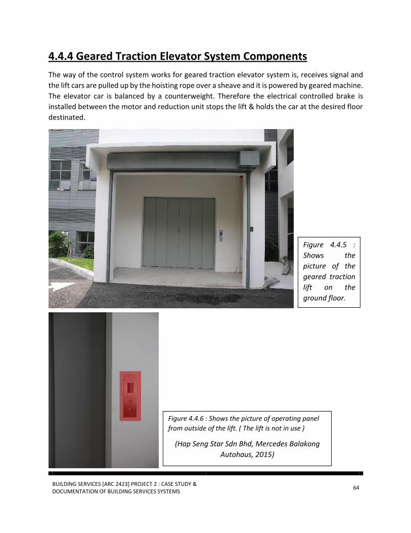
4.4.4 Geared Traction Elevator System Components
The way of the control system works for geared traction elevator system is, receives signal and
the lift cars are pulled up by the hoisting rope over a sheave and it is powered by geared machine.
The elevator car is balanced by a counterweight. Therefore the electrical controlled brake is
installed between the motor and reduction unit stops the lift & holds the car at the desired floor
destinated.
Figure 4.4.5 :
Shows the
picture of the
geared traction
lift on the
ground floor.
Figure 4.4.6 : Shows the picture of operating panel
from outside of the lift. ( The lift is not in use )
(Hap Seng Star Sdn Bhd, Mercedes Balakong
Autohaus, 2015)

BUILDING SERVICES [ARC 2423] PROJECT 2 : CASE STUDY & DOCUMENTATION OF BUILDING SERVICES SYSTEMS
65
4.4.5 Machine Room
The location of the machine room is located above the hoistway on the roof level of the
Mercedes Balakong Autohaus. The machine room is where the control system & geared
machine is placed in.
Figure 4.4.7 ;
Location of
machine
room on roof
level of
Mercedes
Balakong
Autohaus.
Figure 4.4.8 ; Location of car lift below the machine room on roof level of
Mercedes Balakong Autohaus.

BUILDING SERVICES [ARC 2423] PROJECT 2 : CASE STUDY & DOCUMENTATION OF BUILDING SERVICES SYSTEMS
66
Figure 4.4.9 ; Diagram of a geared machine which is located inside the machine room
GEARED MACHINE

BUILDING SERVICES [ARC 2423] PROJECT 2 : CASE STUDY & DOCUMENTATION OF BUILDING SERVICES SYSTEMS
67
Figure 4.4.10 ; Section drawing of a diagram of a geared machine which is located inside the machine
room
GEARED MACHINE
SECTION

BUILDING SERVICES [ARC 2423] PROJECT 2 : CASE STUDY & DOCUMENTATION OF BUILDING SERVICES SYSTEMS
68
4.5 Fire Lift System
The fire lift system is mainly applied all over the building, hence also in the lift. It’s main ability is
for safety. Therefore, the fire indicator will illuminate and a buzzer will sound during fire
emergency operation. While during the fire service operation, the elevators will be back to
ground floor, and lastly the door will be remain open until the fire operation have been dis-alarm.
4.6 Conclusion
Overall conclusion for mechanical transport system would be, Mercedes Balakong Autohaus have
wise choice of having just 2 mechanical transport. As these 2 transports made the transportation
more convenient for the passengers and also transporting the cars. As also the building lift is fully
comply with UBBL and well maintained till today. Lastly, the building & mechanical
transportations are fully functioning well for their building service.

BUILDING SERVICES [ARC 2423] PROJECT 2 : CASE STUDY & DOCUMENTATION OF BUILDING SERVICES SYSTEMS
69
GENERAL CONCLUSION
In conclusion, the building services in Hap Seng Star Sdn Bhd, Balakong Autohaus is both efficient
and sufficient. Majority of its components adhere to their basic requirements and followed the
Uniform Building By-Law codes and the MS 1525 requirements.
Throughout this assignment, we gained the knowledge of being able to identify the system
components involved in the following building services: fire protection system, mechanical
ventilation and air-conditioning system and mechanical transportation system. We also gained
the knowledge of being able to identify the estimate dimensions of the components and the
spaces required for these components.

BUILDING SERVICES [ARC 2423] PROJECT 2 : CASE STUDY & DOCUMENTATION OF BUILDING SERVICES SYSTEMS
70
REFERENCES
Introduction
About us. (n.d.). Retrieved November 22, 2015, from http://www.hapseng.mercedes-
benz.com.my/content/malaysia/retailer/hapseng/en/home/passengercars/home/about_us.html
Malaysia,. Uniform Building By-Laws. Kuala Lumpur: N.p., 1984. Print.
Fire Protection System
Hall, Frederick E. 1997. Building Services and Equipment. Volume 2. 2nd Edition.
Malaysia,. Uniform Building By-Laws. Kuala Lumpur: N.p., 1984. Print.
Ching, Francis D.K. 2012. Building Codes Illustrated. 4th Edition. Wiley.
McMorrough, Julia. 2013. The Architecture Reference +Specification Book. Rockport
How Fires Start. (2012, November 14). How Fires Start. Retrieved October 11, 2014, from http://www.ocfire.com/start.htm
How do sprinklers work – Fire Busters Inc.. (n.d). How do sprinklers work – Fire Busters Inc. . Retrieved September 8,2014, from http://www.firebusters.com/sprforhome/howsprswork.phtml
FireSafeEurope : Active or Passive Protection. (n.d). Fire safe Europe. Retrieved September 6, 2014, from http://www.firesafeeurope.eu/fire-safety/active-or-passive-fire-protection
Malaysia Fire Fighting Equipment | Hose & Fitting Supplier | Mechanical Seal | Oil Seal | Instrumentation Valve & Fitting. (n.d). Fire Detection & Alarm System. Retrieved August 27, 2014, from http”//www.petromas.com.my/catalog/fire-detection-alarm-system-p-146.html

BUILDING SERVICES [ARC 2423] PROJECT 2 : CASE STUDY & DOCUMENTATION OF BUILDING SERVICES SYSTEMS
71
Air Conditioning System
(n.d.). Retrieved November 22, 2015, from http://www.fujiaire.com.my/upload/VRF.pdf
Malaysia,. Uniform Building By-Laws. Kuala Lumpur: N.p., 1984. Print.
What are the main disadvantages of the VRF system? (n.d.). Retrieved November 22, 2015, from http://www.bayt.com/en/specialties/q/118918/what-are-the-main-disadvantages-of-the-vrf-system/ Disadvantages of using a cooling and heating VRV/VRF system in a tropical area. (n.d.). Retrieved
November 22, 2015, from http://hvac-talk.com/vbb/showthread.php?1429131-Disadvantages-of-using-
a-cooling-and-heating-VRV-VRF-system-in-a-tropical-area
(n.d.). Retrieved November 22, 2015, from http://www.fujiaire.com.my/upload/VRF.pdf
Jackson Engineering Advisers. (n.d.). Retrieved November 22, 2015, from http://www.advisers.co.nz/vrf-systems
(n.d.). Retrieved November 22, 2015, from http://www.seedengr.com/Variable Refrigerant Flow Systems.pdf
Mechanical Ventilation System
Malaysia,. Uniform Building By-Laws. Kuala Lumpur: N.p., 1984. Print.
Butler, K. (2015). Mechanical Ventilation. Beama.org.uk. Retrieved 10 May 2015, from http://www.beama.org.uk/en/product-areas/heating-hot-water-- air-movement/mechanical-ventilation/
Airconditioning-systems.com,. (2015). Air Handling Unit. Retrieved 10 May 2015, from http://www.airconditioning-systems.com/air-handling-unit.html
Mechanical Transportation System
Malaysia,. Uniform Building By-Laws. Kuala Lumpur: N.p., 1984. Print.
KONE Elevators/Lifts. (n.d.). Retrieved November 22, 2015, from http://www.kone.my/elevators-lifts/ (n.d.). Retrieved November 22, 2015, from http://www.agc.gov.my/Akta/Vol. 3/Act 139.pdf Ching, Francis D.K. 2012. Building Codes Illustrated. 4th Edition. Wiley.