Effective Strategies for Developing Interactive Learning Objects
Building Interactive Devices and Objects
Prof. Dr. Michael Rohs, Dipl.-Inform. Sven Kratz [email protected]
MHCI Lab, LMU München
Building Interactive Devices and Objects 2 Michael Rohs, LMU München
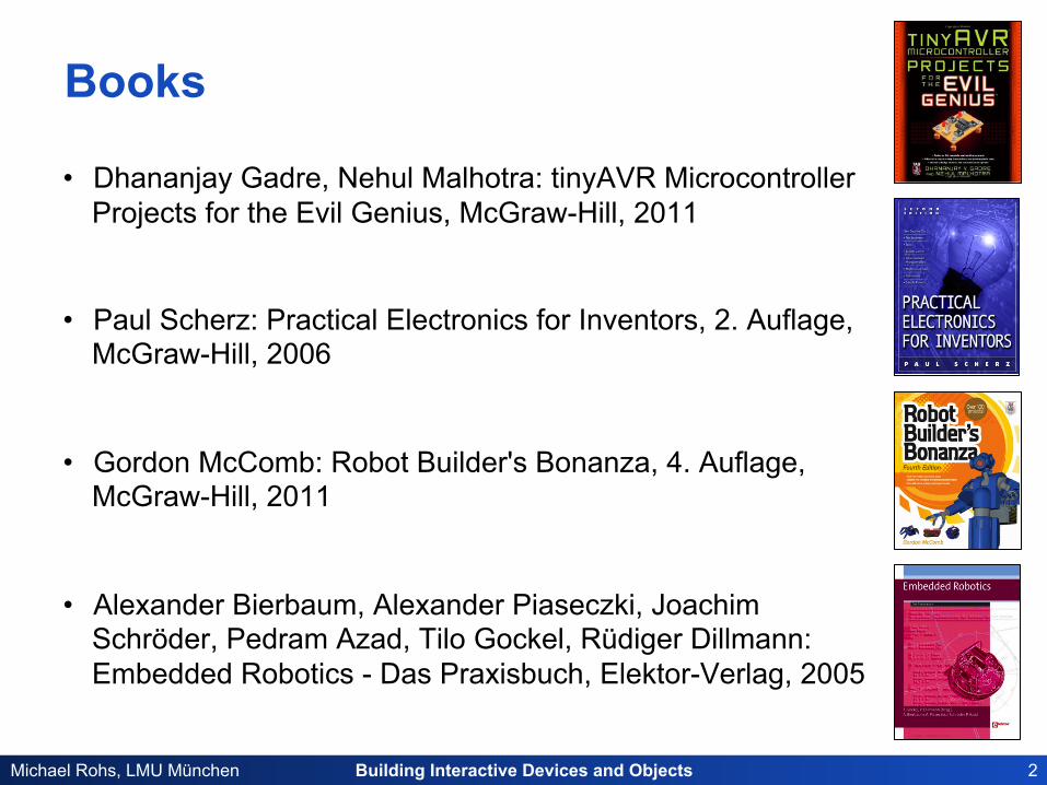
Books
• Dhananjay Gadre, Nehul Malhotra: tinyAVR Microcontroller Projects for the Evil Genius, McGraw-Hill, 2011
• Paul Scherz: Practical Electronics for Inventors, 2. Auflage, McGraw-Hill, 2006
• Gordon McComb: Robot Builder's Bonanza, 4. Auflage, McGraw-Hill, 2011
• Alexander Bierbaum, Alexander Piaseczki, Joachim Schröder, Pedram Azad, Tilo Gockel, Rüdiger Dillmann: Embedded Robotics - Das Praxisbuch, Elektor-Verlag, 2005

Building Interactive Devices and Objects 3 Michael Rohs, LMU München
Schedule # Date Topic Group Ac0vity 1 19.4.2012 Session 1: Introduc5on Team building 2 26.4.2012 Session 2: Microcontrollers & Electronics 3 3.5.2012 Session 3: Sensors Concept development 4 10.5.2012 CHI Concept development 5 17.5.2012 Chris5 Himmelfahrt Concept development 6 24.5.2012 Session 4: Actuators Concept presenta5on, Hardware requ. 7 31.5.2012 Session 5: Physical Objects (Sven) 8 7.6.2012 Frohnleichnam Project 9 14.6.2012 Project 10 21.6.2012 Project 11 28.6.2012 Project 12 5.7.2012 Project 13 12.7.2012 Evalua5on 14 19.7.2012 Evalua5on, Presenta5on
Building Interactive Devices and Objects 4 Michael Rohs, LMU München
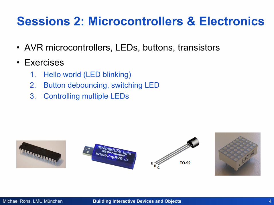
Sessions 2: Microcontrollers & Electronics
• AVR microcontrollers, LEDs, buttons, transistors • Exercises
1. Hello world (LED blinking) 2. Button debouncing, switching LED 3. Controlling multiple LEDs
Building Interactive Devices and Objects 5 Michael Rohs, LMU München
• AVR Eclipse Plugin • Configuring and uploading
• Microcontrollers
• LEDs and buttons
• Exercise 2
Today

Building Interactive Devices and Objects 6 Michael Rohs, LMU München
AVR ECLIPSE PLUGIN

Building Interactive Devices and Objects 7 Michael Rohs, LMU München
AVR Development Toolchain & IDEs
• Free AVR-GCC toolchain – GNU C compiler + linker: avr-gcc (gcc.gnu.org) – C library: avr-libc (www.nongnu.org/avr-libc/) – Down-/uploader: avrdude (www.nongnu.org/avr-libc/)
• Eclipse (cross platform) – http://avr-eclipse.sourceforge.net
• CrossPack for Mac OS X – http://www.obdev.at/products/crosspack/index.html
• WinAVR for Windows – http://winavr.sourceforge.net
• Atmel AVR Studio – http://www.atmel.com
Building Interactive Devices and Objects 8 Michael Rohs, LMU München
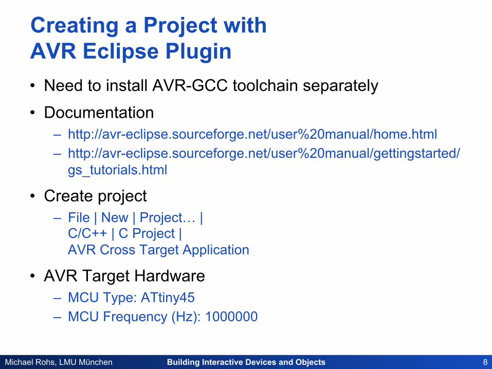
Creating a Project with AVR Eclipse Plugin • Need to install AVR-GCC toolchain separately • Documentation
– http://avr-eclipse.sourceforge.net/user%20manual/home.html – http://avr-eclipse.sourceforge.net/user%20manual/gettingstarted/
gs_tutorials.html
• Create project – File | New | Project… |
C/C++ | C Project | AVR Cross Target Application
• AVR Target Hardware – MCU Type: ATtiny45 – MCU Frequency (Hz): 1000000
Building Interactive Devices and Objects 9 Michael Rohs, LMU München
Building Interactive Devices and Objects 10 Michael Rohs, LMU München
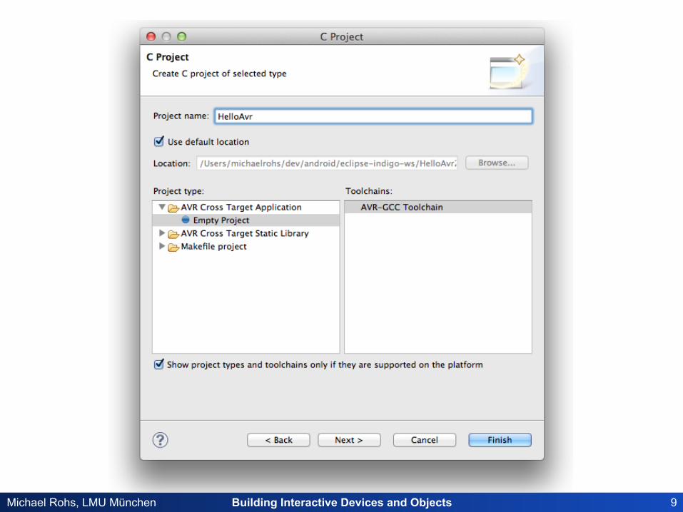
New C Source File
Building Interactive Devices and Objects 11 Michael Rohs, LMU München
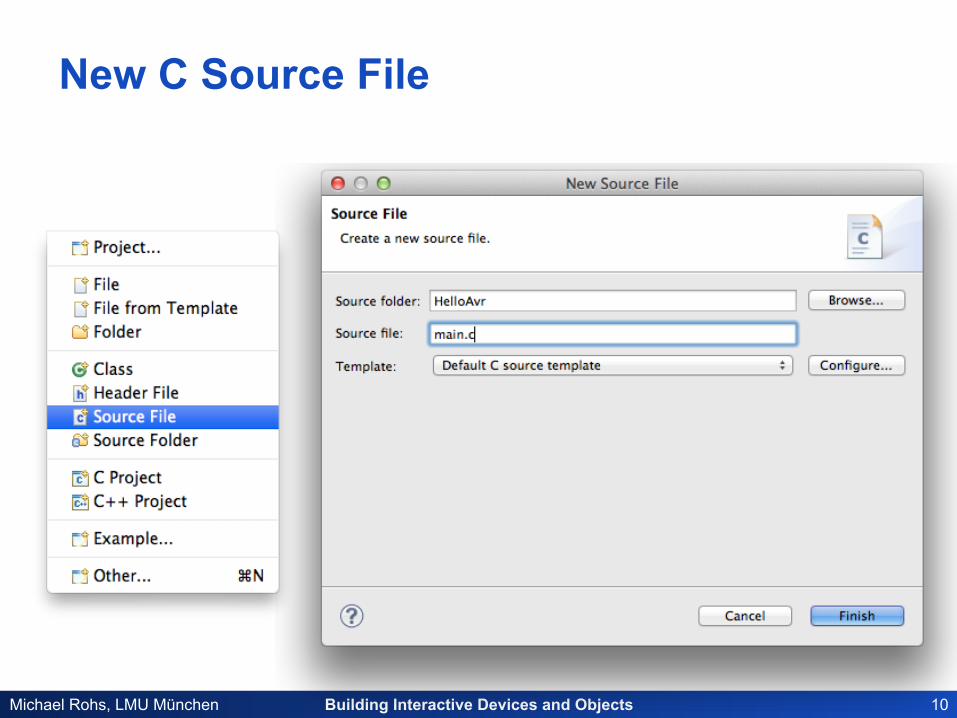
“µC Hello World”: Blinking LED
#include <avr/io.h> #include <util/delay.h>
int main() {
DDRB = 0b010000;
while (1) {
PORTB = 0b010000;
_delay_ms(500);
PORTB = 0b000000;
_delay_ms(500);
}
return 0;
}
ATTiny45
3 2 1 4
6 7 8 5
GND PB4 PB3 PB5 (RESET)
(MOSI) PB0
(MISO) PB1
(SCK) PB2 Vcc
1kΩ
LED red
+5V
Hardware Software
Building Interactive Devices and Objects 12 Michael Rohs, LMU München
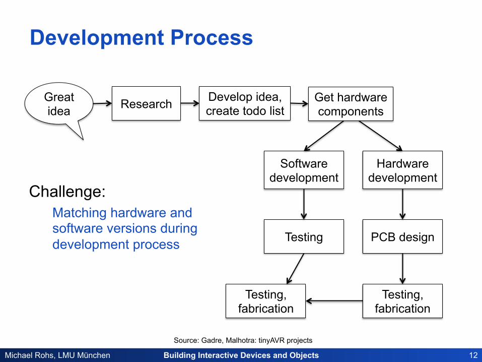
Development Process
Challenge: Matching hardware and software versions during development process
Get hardware components Research Develop idea,
create todo list Great idea
Software development
Hardware development
Testing PCB design
Testing, fabrication
Testing, fabrication
Source: Gadre, Malhotra: tinyAVR projects
Building Interactive Devices and Objects 13 Michael Rohs, LMU München
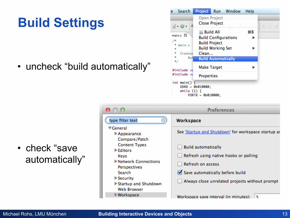
Build Settings
• uncheck “build automatically”
• check “save automatically”
Building Interactive Devices and Objects 14 Michael Rohs, LMU München
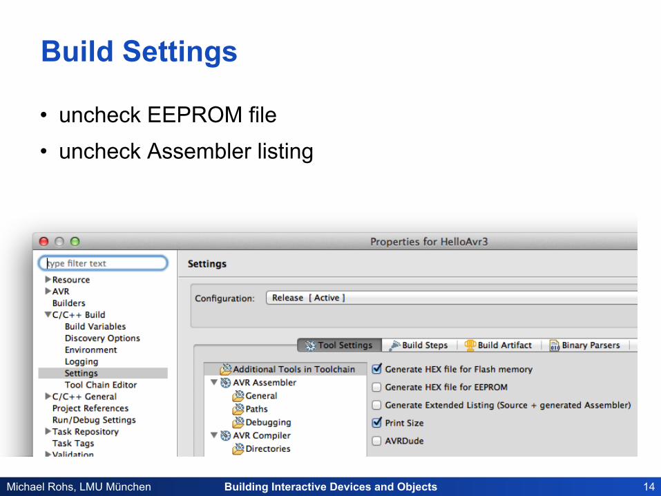
Build Settings
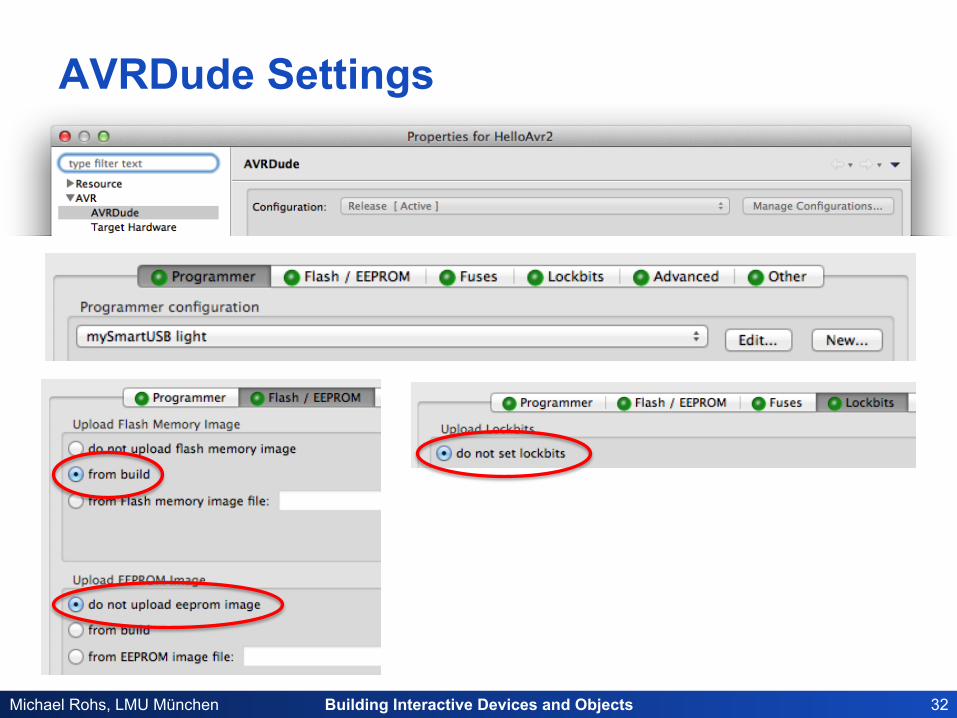
• uncheck EEPROM file • uncheck Assembler listing
Building Interactive Devices and Objects 15 Michael Rohs, LMU München
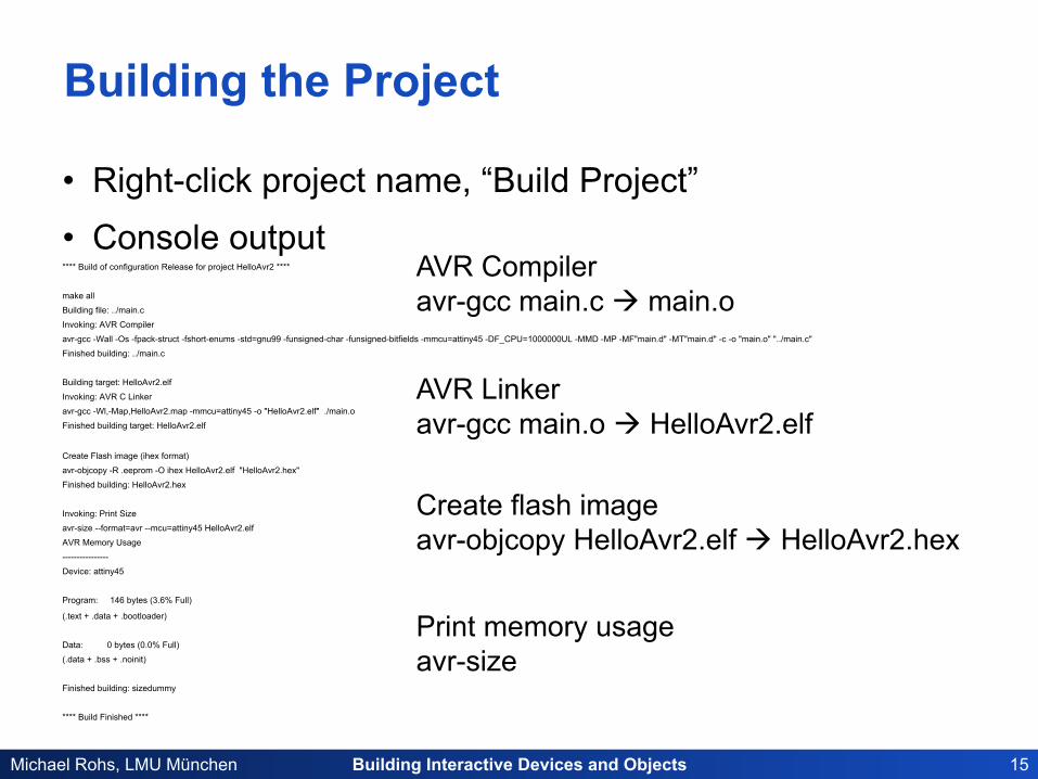
Building the Project
• Right-click project name, “Build Project” • Console output **** Build of configuration Release for project HelloAvr2 ****
make all
Building file: ../main.c
Invoking: AVR Compiler
avr-gcc -Wall -Os -fpack-struct -fshort-enums -std=gnu99 -funsigned-char -funsigned-bitfields -mmcu=attiny45 -DF_CPU=1000000UL -MMD -MP -MF"main.d" -MT"main.d" -c -o "main.o" "../main.c"
Finished building: ../main.c
Building target: HelloAvr2.elf
Invoking: AVR C Linker
avr-gcc -Wl,-Map,HelloAvr2.map -mmcu=attiny45 -o "HelloAvr2.elf" ./main.o
Finished building target: HelloAvr2.elf
Create Flash image (ihex format)
avr-objcopy -R .eeprom -O ihex HelloAvr2.elf "HelloAvr2.hex"
Finished building: HelloAvr2.hex
Invoking: Print Size
avr-size --format=avr --mcu=attiny45 HelloAvr2.elf
AVR Memory Usage
----------------
Device: attiny45
Program: 146 bytes (3.6% Full)
(.text + .data + .bootloader)
Data: 0 bytes (0.0% Full)
(.data + .bss + .noinit)
Finished building: sizedummy
**** Build Finished ****
AVR Linker avr-gcc main.o à HelloAvr2.elf
AVR Compiler avr-gcc main.c à main.o
Create flash image avr-objcopy HelloAvr2.elf à HelloAvr2.hex
Print memory usage avr-size
Building Interactive Devices and Objects 16 Michael Rohs, LMU München
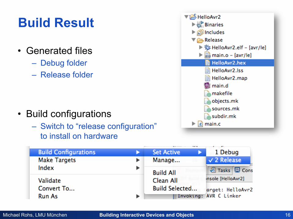
Build Result
• Generated files – Debug folder – Release folder
• Build configurations – Switch to “release configuration”
to install on hardware
Building Interactive Devices and Objects 17 Michael Rohs, LMU München
.c .c
.S
C compiler .S
.S Assembler .o Linker
Lib
startup code
.elf Object Copy
Debugger
.hex
Programmer
User’s input files GCC GNU Binutils AVR Libc GDB / AVaRICE / Simulavr AVRDUDE
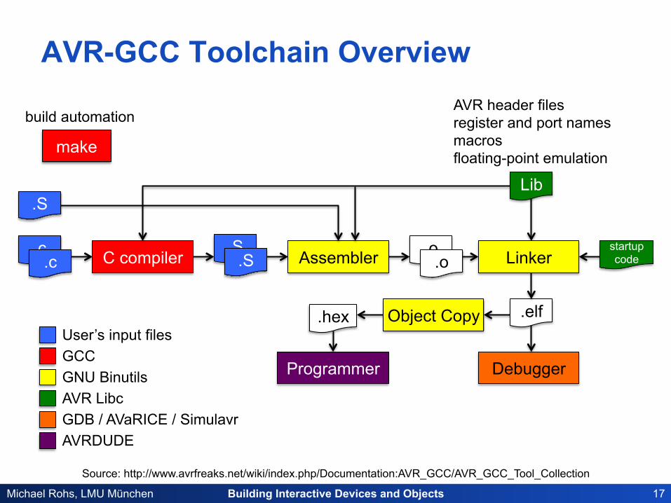
Source: http://www.avrfreaks.net/wiki/index.php/Documentation:AVR_GCC/AVR_GCC_Tool_Collection
AVR-GCC Toolchain Overview AVR header files register and port names macros floating-point emulation
.o
make
build automation
Building Interactive Devices and Objects 18 Michael Rohs, LMU München
Assembly Language
• ATtiny, Atmega – simple instruction sets – for example: ATtiny13 has 120 instructions – reasonably simple to program
• http://avra.sourceforge.net/index.html
Building Interactive Devices and Objects 19 Michael Rohs, LMU München
CONFIGURING AND UPLOADING
Building Interactive Devices and Objects 20 Michael Rohs, LMU München
USB
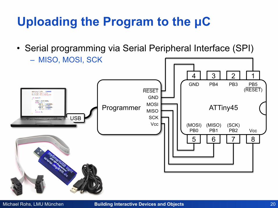
Uploading the Program to the µC
• Serial programming via Serial Peripheral Interface (SPI) – MISO, MOSI, SCK
ATTiny45
3 2 1 4
6 7 8 5
GND PB4 PB3 PB5 (RESET)
(MOSI) PB0
(MISO) PB1
(SCK) PB2 Vcc
Programmer GND
RESET
MOSI MISO SCK Vcc
Building Interactive Devices and Objects 21 Michael Rohs, LMU München
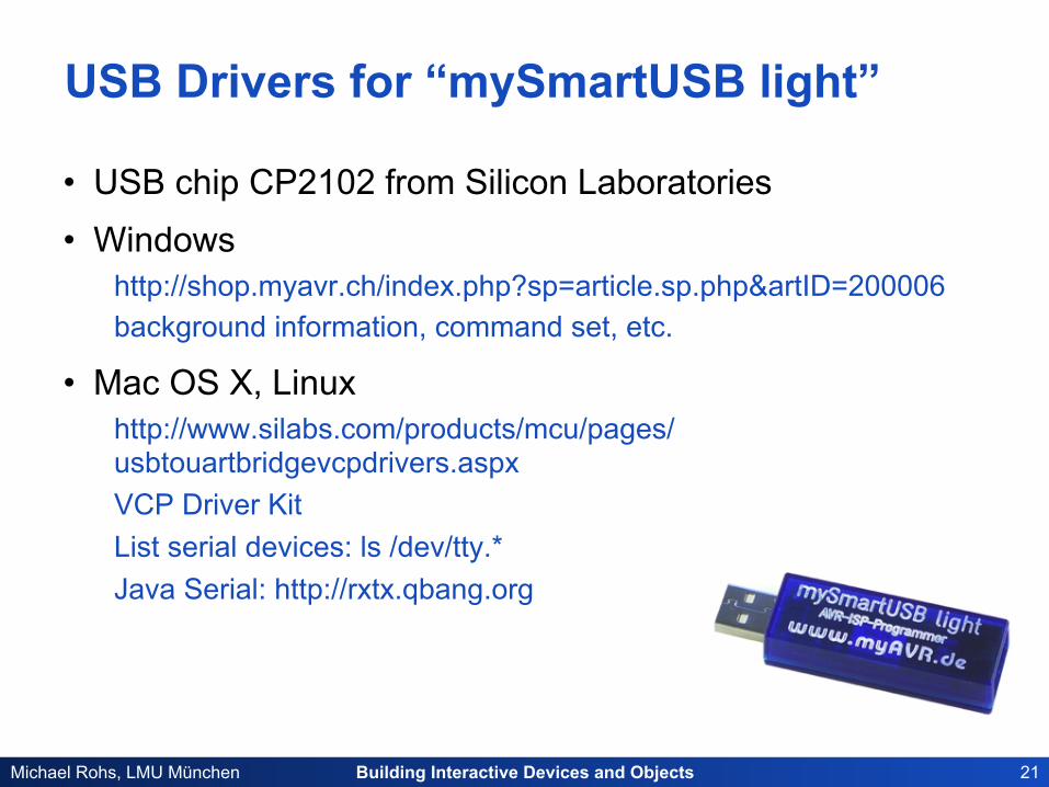
USB Drivers for “mySmartUSB light”
• USB chip CP2102 from Silicon Laboratories • Windows
http://shop.myavr.ch/index.php?sp=article.sp.php&artID=200006 background information, command set, etc.
• Mac OS X, Linux http://www.silabs.com/products/mcu/pages/usbtouartbridgevcpdrivers.aspx VCP Driver Kit List serial devices: ls /dev/tty.* Java Serial: http://rxtx.qbang.org
Building Interactive Devices and Objects 22 Michael Rohs, LMU München
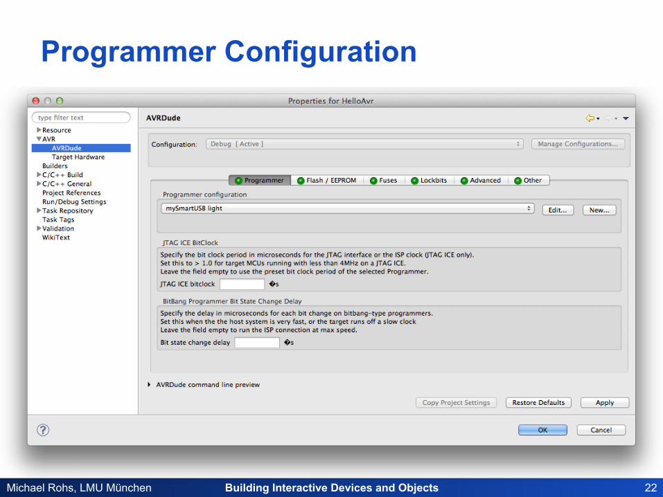
Programmer Configuration
Building Interactive Devices and Objects 23 Michael Rohs, LMU München
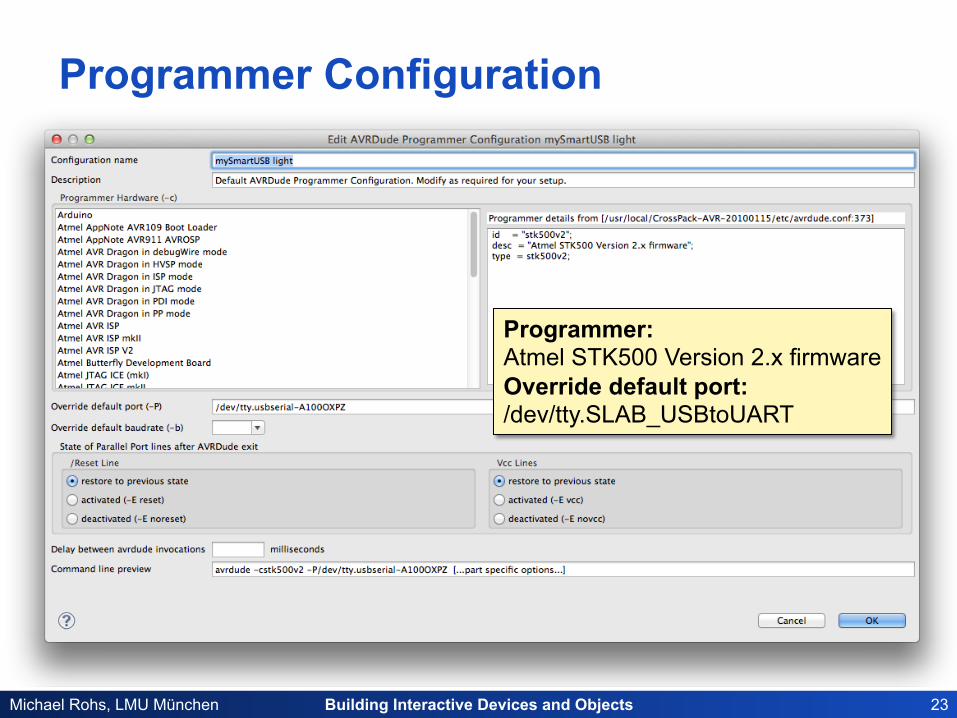
Programmer Configuration
Programmer: Atmel STK500 Version 2.x firmware Override default port: /dev/tty.SLAB_USBtoUART
Building Interactive Devices and Objects 24 Michael Rohs, LMU München
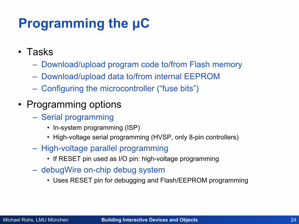
Programming the µC
• Tasks – Download/upload program code to/from Flash memory – Download/upload data to/from internal EEPROM – Configuring the microcontroller (“fuse bits”)
• Programming options – Serial programming
• In-system programming (ISP) • High-voltage serial programming (HVSP, only 8-pin controllers)
– High-voltage parallel programming • If RESET pin used as I/O pin: high-voltage programming
– debugWire on-chip debug system • Uses RESET pin for debugging and Flash/EEPROM programming
Building Interactive Devices and Objects 25 Michael Rohs, LMU München
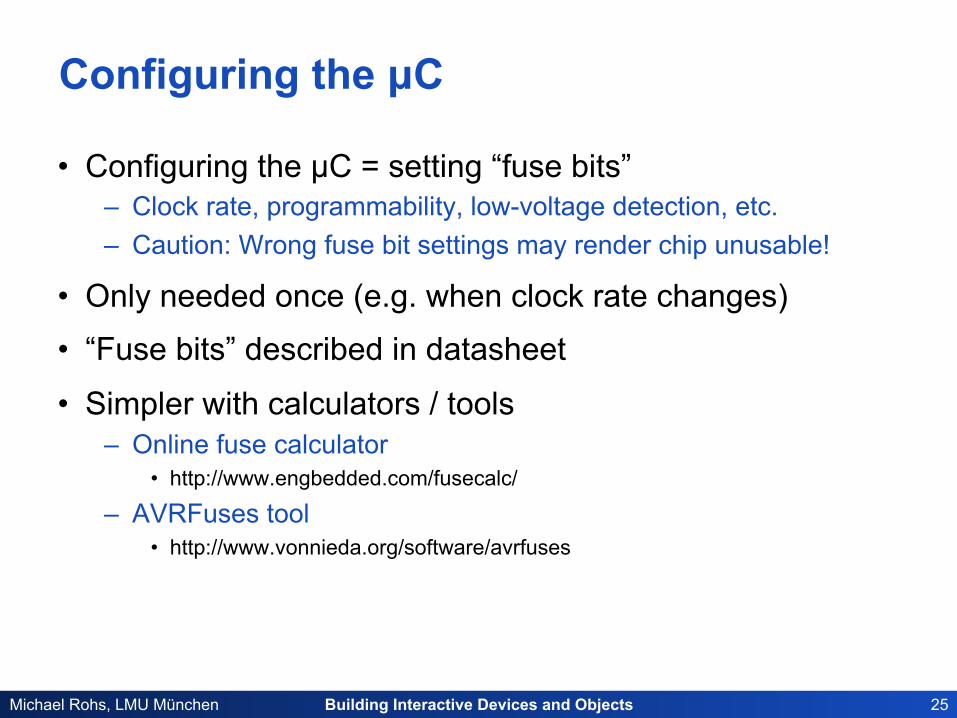
Configuring the µC
• Configuring the µC = setting “fuse bits” – Clock rate, programmability, low-voltage detection, etc. – Caution: Wrong fuse bit settings may render chip unusable!
• Only needed once (e.g. when clock rate changes)
• “Fuse bits” described in datasheet
• Simpler with calculators / tools – Online fuse calculator
• http://www.engbedded.com/fusecalc/
– AVRFuses tool • http://www.vonnieda.org/software/avrfuses
Building Interactive Devices and Objects 26 Michael Rohs, LMU München
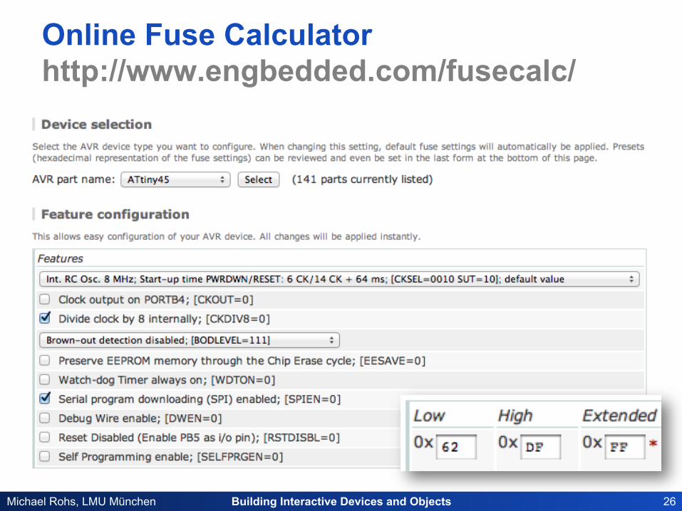
Online Fuse Calculator http://www.engbedded.com/fusecalc/
Building Interactive Devices and Objects 27 Michael Rohs, LMU München
AVR Clock Options
• Clock frequency can be chosen – Application requirements, power consumption – Clock prescaler register (divide clock by factor) – Component clocks can be disabled to reduce power consumption
• Clock source can be chosen – Internal resistor capacitor (RC) oscillator
• Convenient, but not precise (temperature, operating voltage) • ATtiny13: 4.8MHz, 9.6MHz (at 3V and 25°C), 128kHz (low power)
– External crystal oscillator • Highly precise, requires external quartz
• Clock source distributed to modules – CLKCPU, CLKI/O, CLKflash, CLKADC
– CLKADC allows switching off other clocks during ADC conversion
Building Interactive Devices and Objects 28 Michael Rohs, LMU München
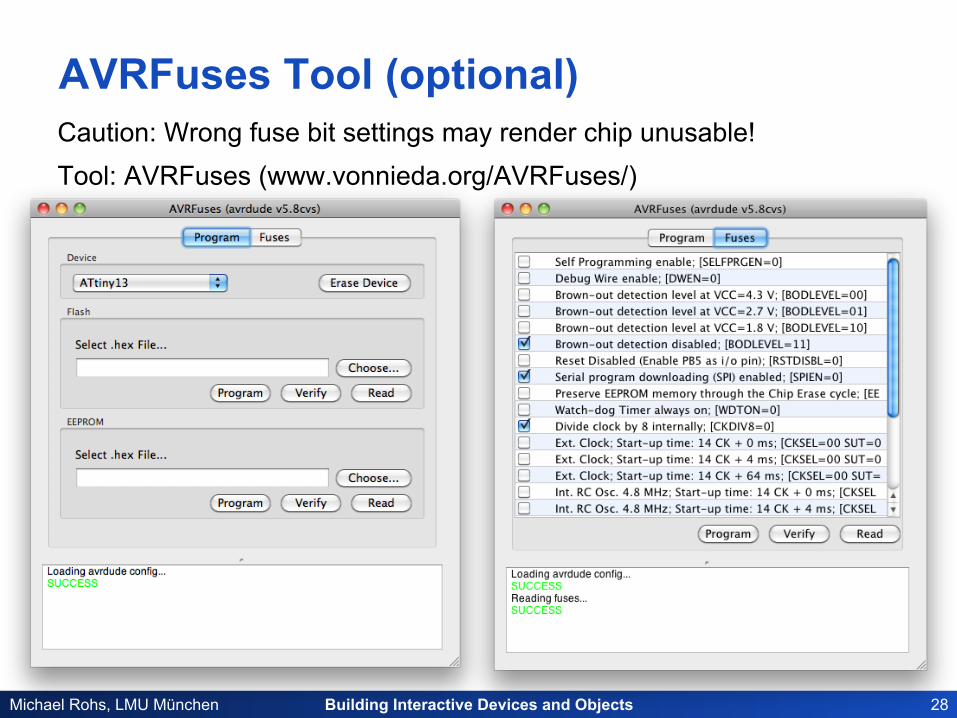
AVRFuses Tool (optional) Caution: Wrong fuse bit settings may render chip unusable! Tool: AVRFuses (www.vonnieda.org/AVRFuses/)
Building Interactive Devices and Objects 29 Michael Rohs, LMU München
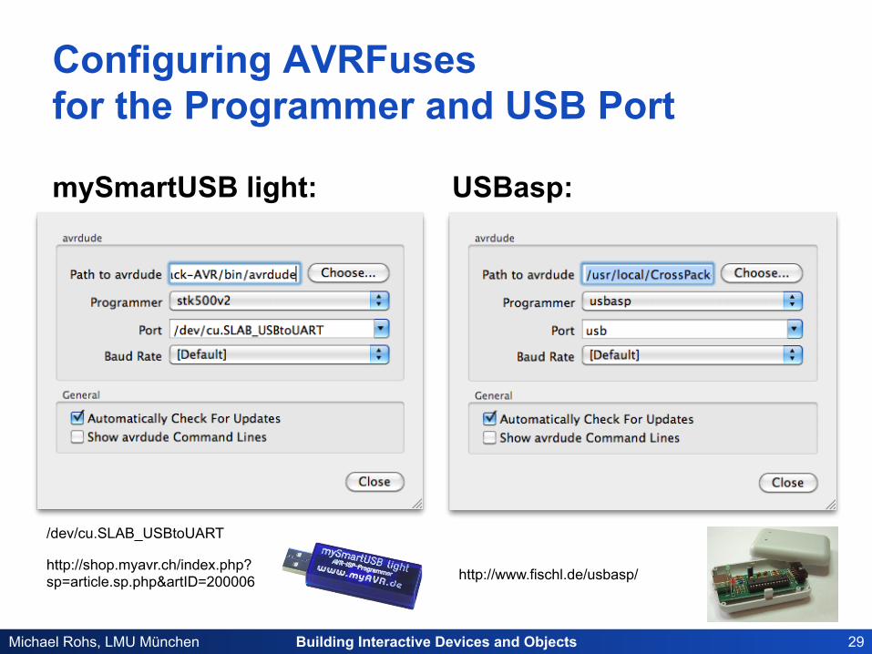
Configuring AVRFuses for the Programmer and USB Port
mySmartUSB light: USBasp:
http://www.fischl.de/usbasp/ http://shop.myavr.ch/index.php? sp=article.sp.php&artID=200006
/dev/cu.SLAB_USBtoUART
Building Interactive Devices and Objects 30 Michael Rohs, LMU München
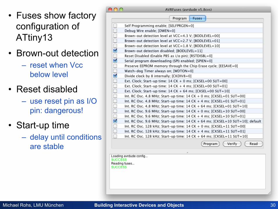
• Fuses show factory configuration of ATtiny13
• Brown-out detection – reset when Vcc
below level
• Reset disabled – use reset pin as I/O
pin: dangerous!
• Start-up time – delay until conditions
are stable
Building Interactive Devices and Objects 31 Michael Rohs, LMU München
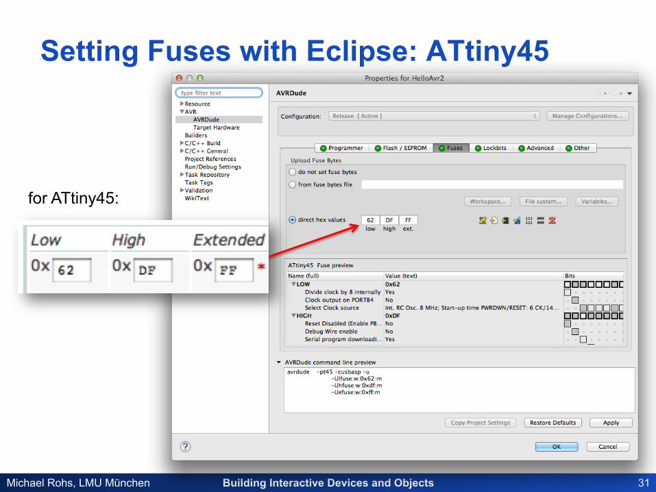
Setting Fuses with Eclipse: ATtiny45
for ATtiny45:
Building Interactive Devices and Objects 32 Michael Rohs, LMU München
AVRDude Settings
Building Interactive Devices and Objects 33 Michael Rohs, LMU München
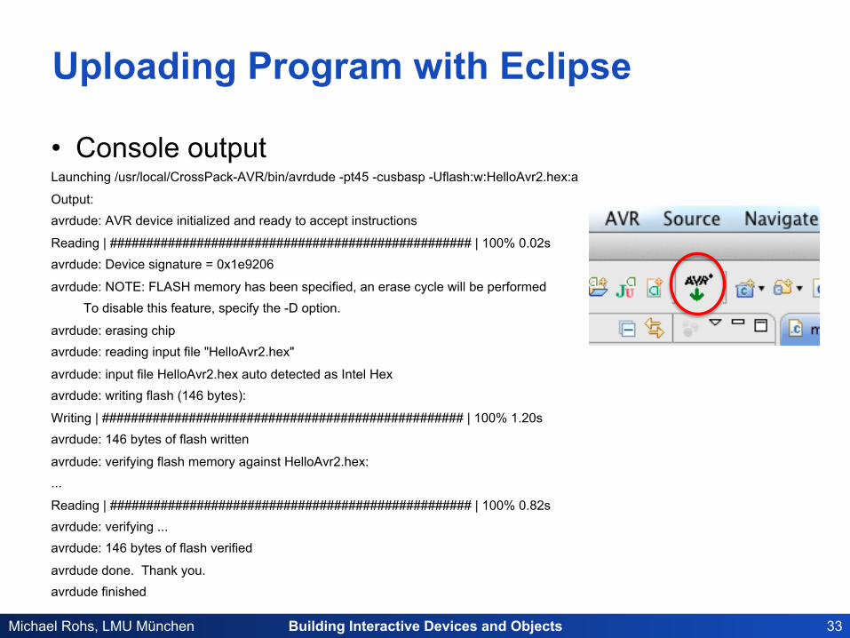
Uploading Program with Eclipse
• Console output Launching /usr/local/CrossPack-AVR/bin/avrdude -pt45 -cusbasp -Uflash:w:HelloAvr2.hex:a
Output: avrdude: AVR device initialized and ready to accept instructions
Reading | ################################################## | 100% 0.02s avrdude: Device signature = 0x1e9206
avrdude: NOTE: FLASH memory has been specified, an erase cycle will be performed To disable this feature, specify the -D option.
avrdude: erasing chip avrdude: reading input file "HelloAvr2.hex"
avrdude: input file HelloAvr2.hex auto detected as Intel Hex avrdude: writing flash (146 bytes):
Writing | ################################################## | 100% 1.20s avrdude: 146 bytes of flash written
avrdude: verifying flash memory against HelloAvr2.hex: ...
Reading | ################################################## | 100% 0.82s avrdude: verifying ... avrdude: 146 bytes of flash verified
avrdude done. Thank you. avrdude finished
Building Interactive Devices and Objects 34 Michael Rohs, LMU München
AVR Eclipse Plugin – Advanced Settings
• Target Hardware: Specify target microcontroller – MCU Type: ATtiny45 (later will also use ATmega8) – MCU Clock Frequency: typical values are 1 MHz (internal),
8 MHz (external quartz) , 16 MHz (external quartz)
• AVRDude: Install program on microcontroller – Programmer: Atmel STK500 Version 2.x firmware – Override default port: /dev/tty.usbserial-A100OXPZ
Building Interactive Devices and Objects 35 Michael Rohs, LMU München
Command Line Without Eclipse
• Compiling – avr-gcc -Os -mmcu=attiny45 main.c
• Format conversion – avr-objcopy -R .eeprom -O ihex a.out a.hex
• Uploading – avrdude -pt45 -cstk500v2 -P/dev/ttyUSB0 -Uflash:w:a.hex:a
Source: Mikołaj Dądela
Building Interactive Devices and Objects 36 Michael Rohs, LMU München
MICROCONTROLLERS
Building Interactive Devices and Objects 37 Michael Rohs, LMU München
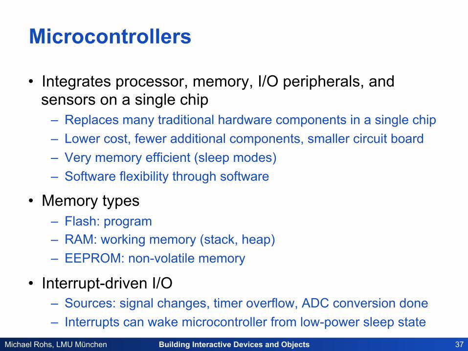
Microcontrollers
• Integrates processor, memory, I/O peripherals, and sensors on a single chip
– Replaces many traditional hardware components in a single chip – Lower cost, fewer additional components, smaller circuit board – Very memory efficient (sleep modes) – Software flexibility through software
• Memory types – Flash: program – RAM: working memory (stack, heap) – EEPROM: non-volatile memory
• Interrupt-driven I/O – Sources: signal changes, timer overflow, ADC conversion done – Interrupts can wake microcontroller from low-power sleep state
Building Interactive Devices and Objects 38 Michael Rohs, LMU München
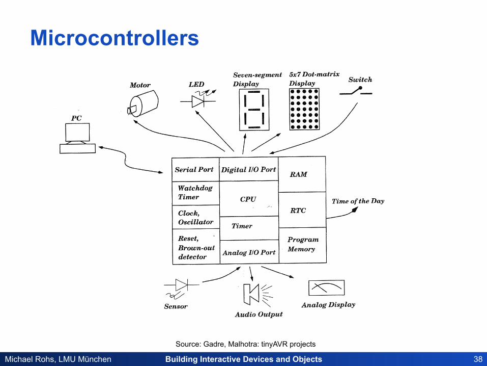
Microcontrollers
Source: Gadre, Malhotra: tinyAVR projects
Building Interactive Devices and Objects 39 Michael Rohs, LMU München
Microcontrollers
• I/O Pins – Used as input or output (controlled by software) – Serial communications (UART, I2C, SPI) – Signal generation (PWM, timers) – Analog input (ADC conversion)
• Development – In-circuit programming and debugging, field update of firmware – Programming in assembly language or C
• Selectable clock frequencies – Lower clock rate à less energy
• No floating point unit (typically)

Building Interactive Devices and Objects 40 Michael Rohs, LMU München
Atmel AVR: ATtiny, ATmega
• 8-bit RISC chip, Harvard architecture • ATtiny
1–8 kB program memory 6–32-pin package www.atmel.com/dyn/products/param_table.asp?category_id=163&family_id=607&subfamily_id=791
• ATmega 4–256 kB program memory 28–100-pin package Extended instruction set
• Multiply instructions • Handling larger program memories
www.atmel.com/dyn/products/param_table.asp?category_id=163&family_id=607&subfamily_id=760
• Large family of devices, specific features
ATtiny13
ATmega328P
Building Interactive Devices and Objects 41 Michael Rohs, LMU München
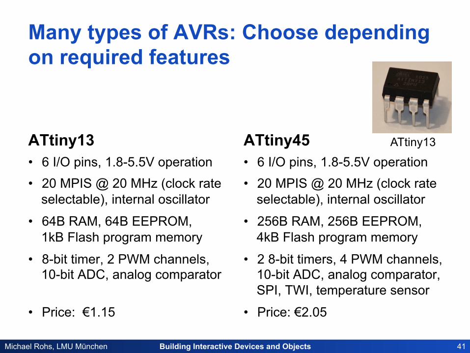
Many types of AVRs: Choose depending on required features
ATtiny13 • 6 I/O pins, 1.8-5.5V operation • 20 MPIS @ 20 MHz (clock rate
selectable), internal oscillator
• 64B RAM, 64B EEPROM, 1kB Flash program memory
• 8-bit timer, 2 PWM channels, 10-bit ADC, analog comparator
• Price: €1.15
ATtiny45 • 6 I/O pins, 1.8-5.5V operation • 20 MPIS @ 20 MHz (clock rate
selectable), internal oscillator
• 256B RAM, 256B EEPROM, 4kB Flash program memory
• 2 8-bit timers, 4 PWM channels, 10-bit ADC, analog comparator, SPI, TWI, temperature sensor
• Price: €2.05
ATtiny13
Building Interactive Devices and Objects 42 Michael Rohs, LMU München
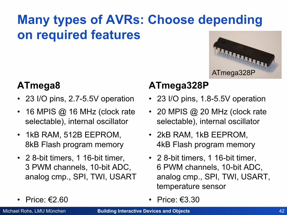
Many types of AVRs: Choose depending on required features
ATmega8 • 23 I/O pins, 2.7-5.5V operation • 16 MPIS @ 16 MHz (clock rate
selectable), internal oscillator
• 1kB RAM, 512B EEPROM, 8kB Flash program memory
• 2 8-bit timers, 1 16-bit timer, 3 PWM channels, 10-bit ADC, analog cmp., SPI, TWI, USART
• Price: €2.60
ATmega328P • 23 I/O pins, 1.8-5.5V operation • 20 MPIS @ 20 MHz (clock rate
selectable), internal oscillator
• 2kB RAM, 1kB EEPROM, 4kB Flash program memory
• 2 8-bit timers, 1 16-bit timer, 6 PWM channels, 10-bit ADC, analog cmp., SPI, TWI, USART, temperature sensor
• Price: €3.30
ATmega328P
Building Interactive Devices and Objects 43 Michael Rohs, LMU München
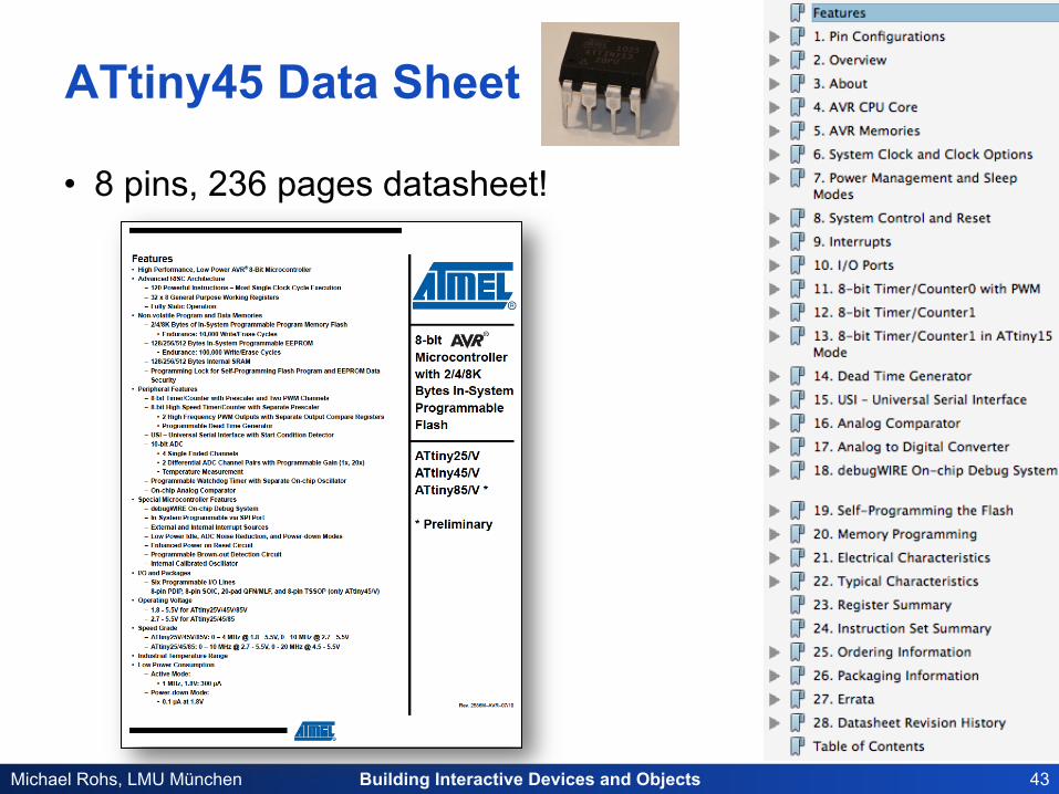
ATtiny45 Data Sheet
• 8 pins, 236 pages datasheet!
Building Interactive Devices and Objects 44 Michael Rohs, LMU München
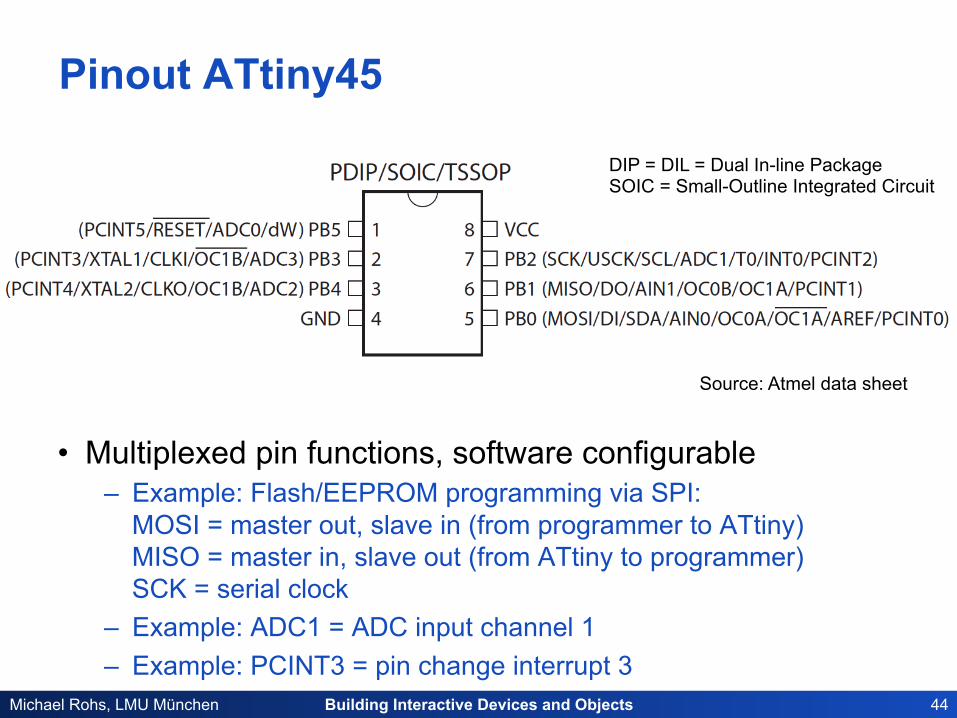
Pinout ATtiny45
• Multiplexed pin functions, software configurable – Example: Flash/EEPROM programming via SPI:
MOSI = master out, slave in (from programmer to ATtiny) MISO = master in, slave out (from ATtiny to programmer) SCK = serial clock
– Example: ADC1 = ADC input channel 1 – Example: PCINT3 = pin change interrupt 3
DIP = DIL = Dual In-line Package SOIC = Small-Outline Integrated Circuit
Source: Atmel data sheet
Building Interactive Devices and Objects 45 Michael Rohs, LMU München
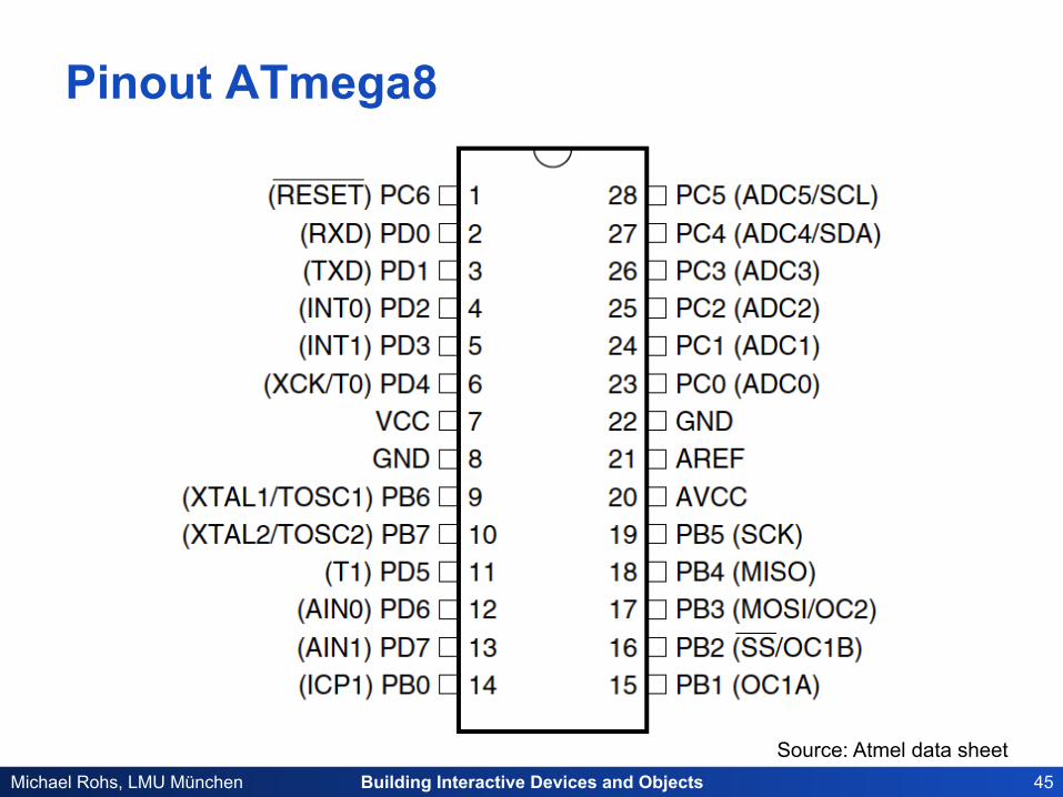
Pinout ATmega8
Source: Atmel data sheet
Building Interactive Devices and Objects 46 Michael Rohs, LMU München
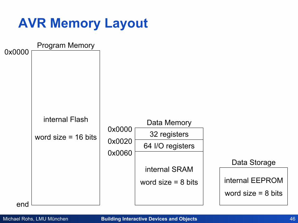
AVR Memory Layout
internal Flash
word size = 16 bits
Program Memory
internal SRAM
word size = 8 bits internal EEPROM
word size = 8 bits
32 registers 64 I/O registers
Data Storage
Data Memory
0x0000
end
0x0000 0x0020 0x0060
Building Interactive Devices and Objects 47 Michael Rohs, LMU München
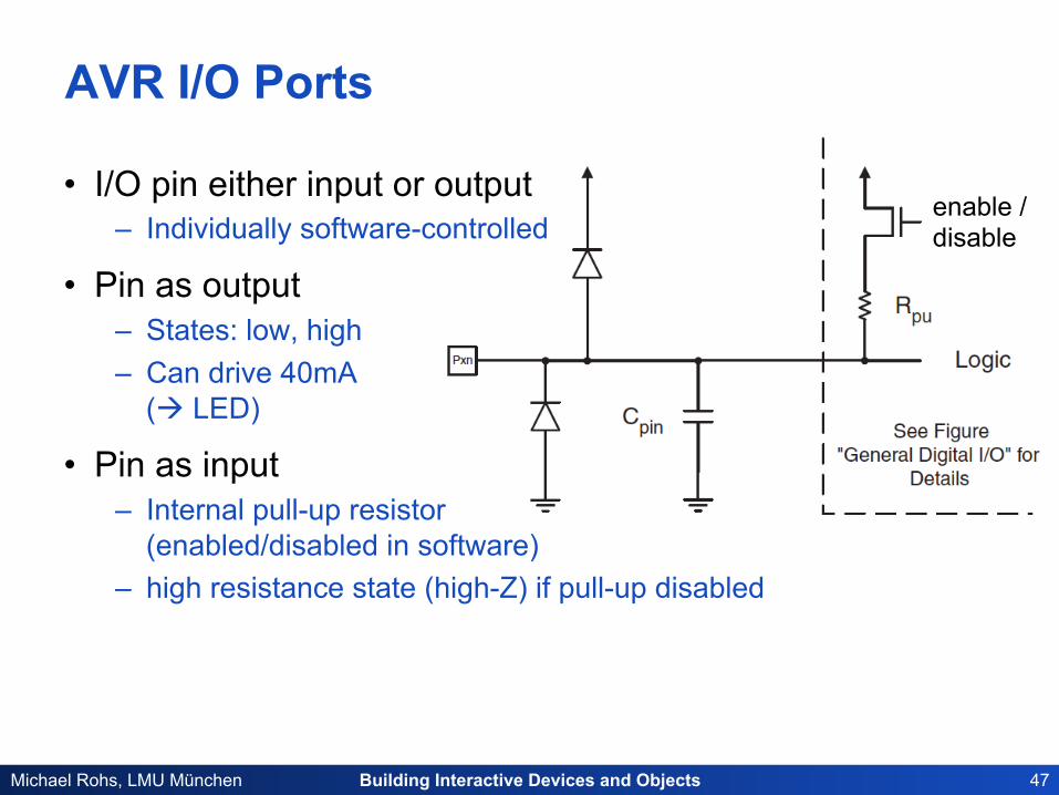
AVR I/O Ports
• I/O pin either input or output – Individually software-controlled
• Pin as output – States: low, high – Can drive 40mA
(à LED)
• Pin as input – Internal pull-up resistor
(enabled/disabled in software) – high resistance state (high-Z) if pull-up disabled
enable /disable
Building Interactive Devices and Objects 48 Michael Rohs, LMU München
Accessing the I/O Ports
• Three memory addresses for each I/O port – Data Direction Register: DDRx
• 1 = output • 0 = input
– Data Register: PORTx • if input: 1 = pull-up enabled, 0 = pull-up disabled • if output: 1 = PIN driven high, 0 = PIN driven low
– Port Input Pins: PINx • read: PIN state (independent of DDRx) • write 1: toggles PORTx enable/
disable
Building Interactive Devices and Objects 49 Michael Rohs, LMU München
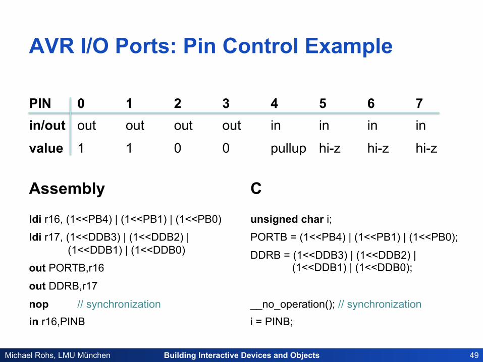
AVR I/O Ports: Pin Control Example
PIN 0 1 2 3 4 5 6 7 in/out out out out out in in in in
value 1 1 0 0 pullup hi-z hi-z hi-z
ldi r16, (1<<PB4) | (1<<PB1) | (1<<PB0)
ldi r17, (1<<DDB3) | (1<<DDB2) | (1<<DDB1) | (1<<DDB0)
out PORTB,r16
out DDRB,r17
nop // synchronization in r16,PINB
unsigned char i; PORTB = (1<<PB4) | (1<<PB1) | (1<<PB0);
DDRB = (1<<DDB3) | (1<<DDB2) | (1<<DDB1) | (1<<DDB0);
__no_operation(); // synchronization i = PINB;
Assembly C

Building Interactive Devices and Objects 50 Michael Rohs, LMU München
External Clock: Quartz Crystal Oscillators
ATtiny45
3 2 1 4
6 7 8 5
GND PB4 XTAL2
PB3 XTAL1
PB5 (RESET)
(MOSI) PB0
(MISO) PB1
(SCK) PB2 Vcc
22 pF
+5V
• More precise than internal oscillators
• Quartz 1..20 MHz
• Ceramic capacitors 12-22pF
• Place quartz and capacitors close to AVR pins
• Change CLKSEL fuse bits
22 pF
1..20 MHz
Building Interactive Devices and Objects 51 Michael Rohs, LMU München
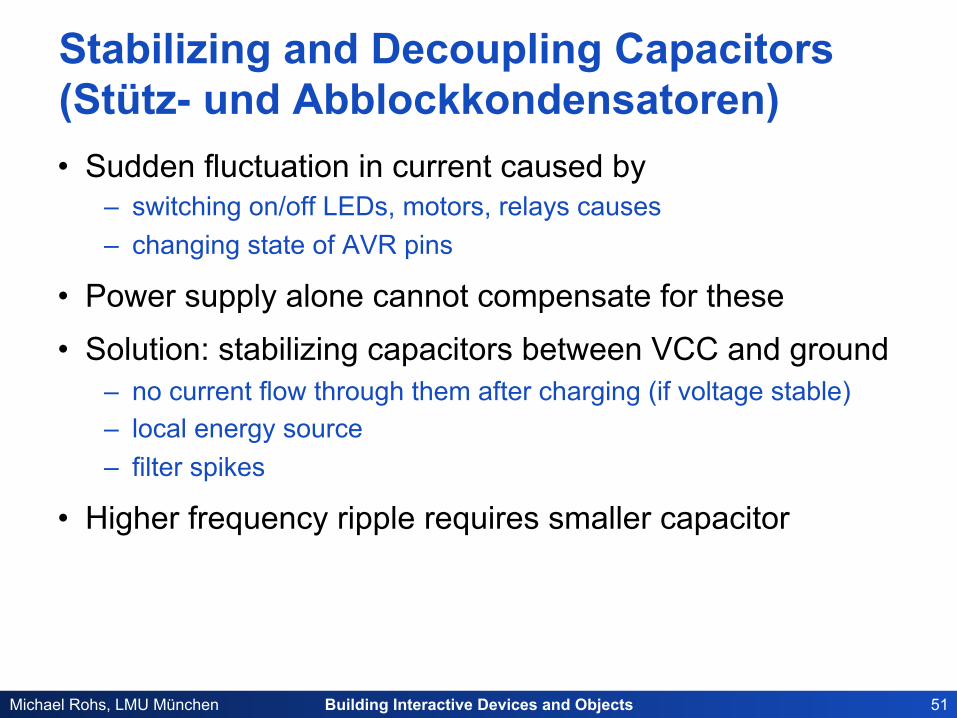
Stabilizing and Decoupling Capacitors (Stütz- und Abblockkondensatoren) • Sudden fluctuation in current caused by
– switching on/off LEDs, motors, relays causes – changing state of AVR pins
• Power supply alone cannot compensate for these
• Solution: stabilizing capacitors between VCC and ground – no current flow through them after charging (if voltage stable) – local energy source – filter spikes
• Higher frequency ripple requires smaller capacitor
Building Interactive Devices and Objects 52 Michael Rohs, LMU München
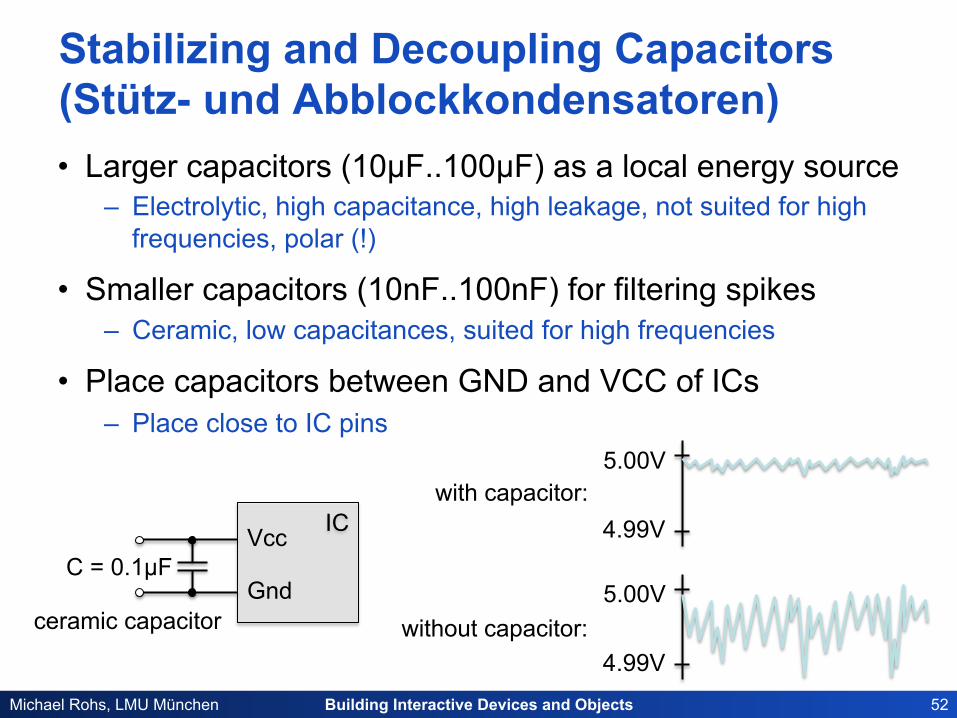
Stabilizing and Decoupling Capacitors (Stütz- und Abblockkondensatoren) • Larger capacitors (10µF..100µF) as a local energy source
– Electrolytic, high capacitance, high leakage, not suited for high frequencies, polar (!)
• Smaller capacitors (10nF..100nF) for filtering spikes – Ceramic, low capacitances, suited for high frequencies
• Place capacitors between GND and VCC of ICs – Place close to IC pins
IC Vcc
Gnd C = 0.1µF
5.00V
4.99V
5.00V
4.99V
with capacitor:
without capacitor: ceramic capacitor
Building Interactive Devices and Objects 53 Michael Rohs, LMU München
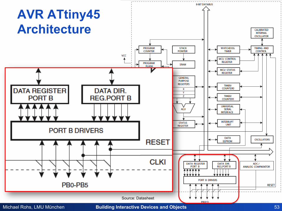
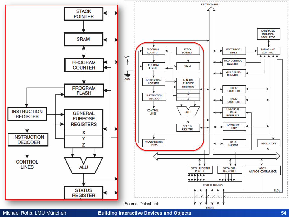
AVR ATtiny45 Architecture
Source: Datasheet
Building Interactive Devices and Objects 54 Michael Rohs, LMU München
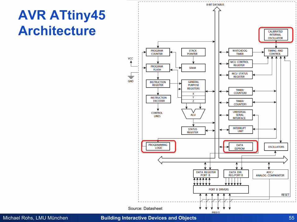
AVR ATtiny45 Architecture
Source: Datasheet
Building Interactive Devices and Objects 55 Michael Rohs, LMU München
Source: Datasheet
AVR ATtiny45 Architecture
Building Interactive Devices and Objects 56 Michael Rohs, LMU München
LEDS & BUTTONS
Building Interactive Devices and Objects 57 Michael Rohs, LMU München
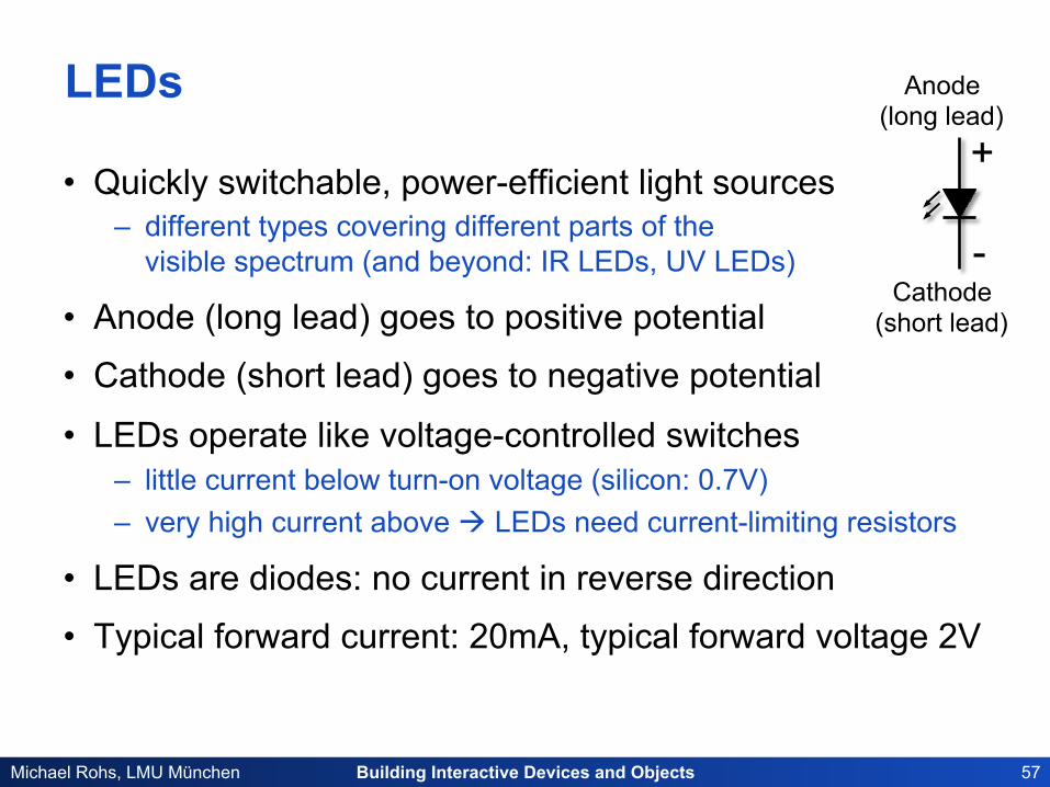
LEDs
• Quickly switchable, power-efficient light sources – different types covering different parts of the
visible spectrum (and beyond: IR LEDs, UV LEDs)
• Anode (long lead) goes to positive potential
• Cathode (short lead) goes to negative potential
• LEDs operate like voltage-controlled switches – little current below turn-on voltage (silicon: 0.7V) – very high current above à LEDs need current-limiting resistors
• LEDs are diodes: no current in reverse direction
• Typical forward current: 20mA, typical forward voltage 2V
Cathode (short lead)
Anode (long lead)
+
-
Building Interactive Devices and Objects 58 Michael Rohs, LMU München
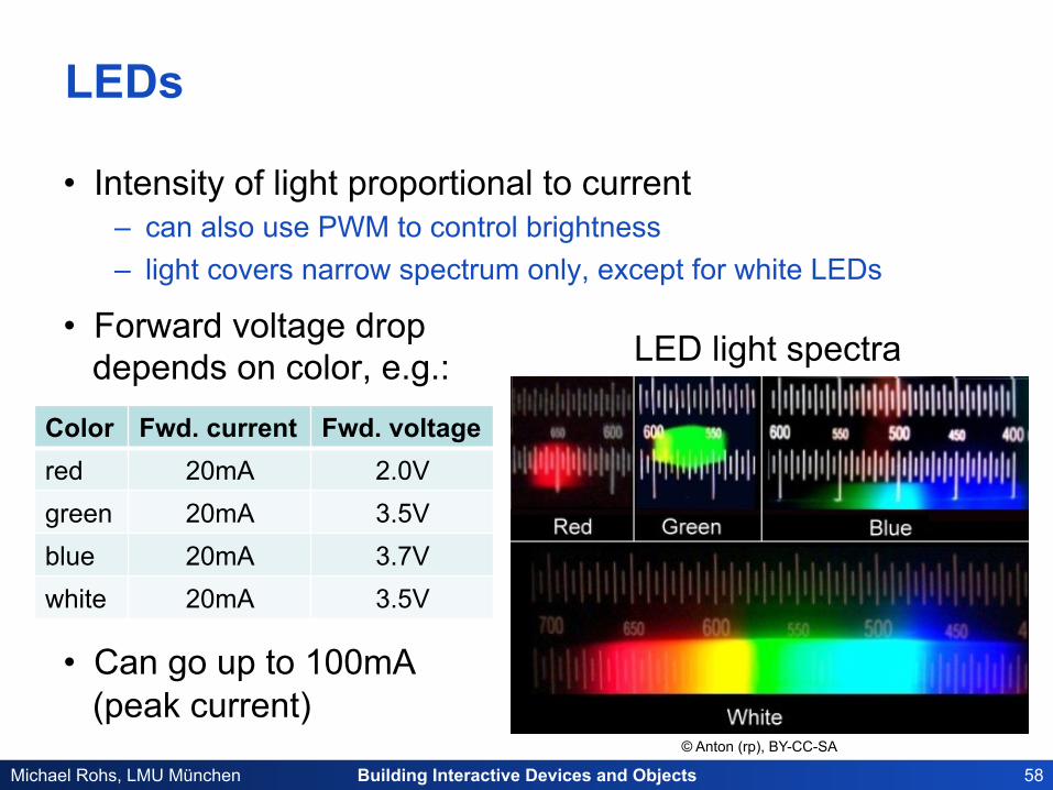
LEDs
• Intensity of light proportional to current – can also use PWM to control brightness – light covers narrow spectrum only, except for white LEDs
• Forward voltage drop depends on color, e.g.:
• Can go up to 100mA (peak current)
© Anton (rp), BY-CC-SA
LED light spectra
Color Fwd. current Fwd. voltage red 20mA 2.0V green 20mA 3.5V blue 20mA 3.7V white 20mA 3.5V
Building Interactive Devices and Objects 59 Michael Rohs, LMU München
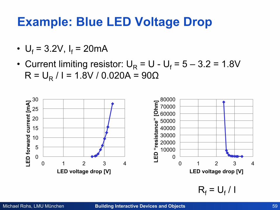
Example: Blue LED Voltage Drop
• Uf = 3.2V, If = 20mA • Current limiting resistor: UR = U - Uf = 5 – 3.2 = 1.8V
R = UR / I = 1.8V / 0.020A = 90Ω
0
5
10
15
20
25
30
0 1 2 3 4 LED
forw
ard
curr
ent [
mA
]
LED voltage drop [V]
0 10000 20000 30000 40000 50000 60000 70000 80000
0 1 2 3 4 LED
“re
sist
ance
” [O
hm]
LED voltage drop [V]
Rf = Uf / I
Building Interactive Devices and Objects 60 Michael Rohs, LMU München
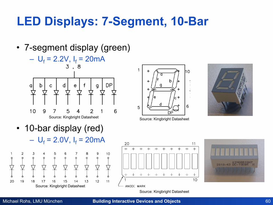
LED Displays: 7-Segment, 10-Bar
• 7-segment display (green) – Uf = 2.2V, If = 20mA
• 10-bar display (red) – Uf = 2.0V, If = 20mA
Source: Kingbright Datasheet Source: Kingbright Datasheet
Source: Kingbright Datasheet Source: Kingbright Datasheet
Building Interactive Devices and Objects 61 Michael Rohs, LMU München
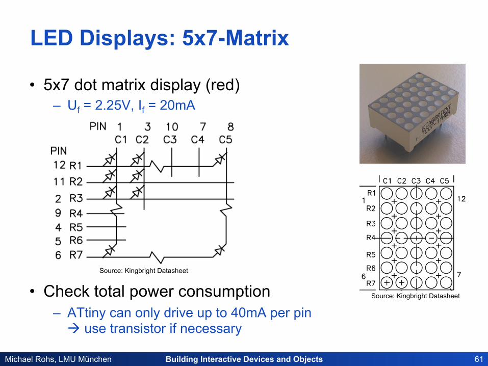
LED Displays: 5x7-Matrix
• 5x7 dot matrix display (red) – Uf = 2.25V, If = 20mA
• Check total power consumption – ATtiny can only drive up to 40mA per pin
à use transistor if necessary
Source: Kingbright Datasheet
Source: Kingbright Datasheet
Building Interactive Devices and Objects 62 Michael Rohs, LMU München
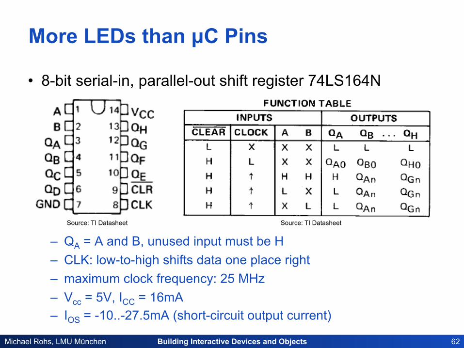
More LEDs than µC Pins
• 8-bit serial-in, parallel-out shift register 74LS164N
– QA = A and B, unused input must be H – CLK: low-to-high shifts data one place right – maximum clock frequency: 25 MHz – Vcc = 5V, ICC = 16mA – IOS = -10..-27.5mA (short-circuit output current)
Source: TI Datasheet Source: TI Datasheet
Building Interactive Devices and Objects 63 Michael Rohs, LMU München
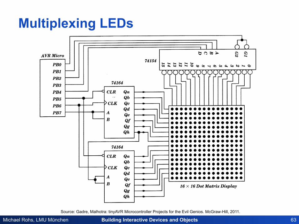
Multiplexing LEDs
Source: Gadre, Malhotra: tinyAVR Microcontroller Projects for the Evil Genios. McGraw-Hill, 2011.

Building Interactive Devices and Objects 64 Michael Rohs, LMU München
Charlieplexing LEDs LED Pin1 Pin2 Pin3 D1 1 0 Z D3 Z 1 0 D6 1 Z 0 D4 Z 0 1 D2 0 1 Z D5 0 Z 1
• Enables one LED at a time – N LEDs, each only on 1/Nth of the time
• Z = tri-state (high impedance state, “no” current)
Source: Wikipedia, Author: Dan Kouba, public domain
Building Interactive Devices and Objects 65 Michael Rohs, LMU München
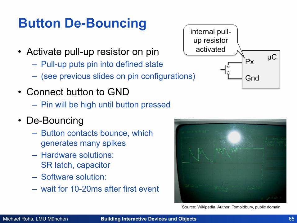
Button De-Bouncing
• Activate pull-up resistor on pin – Pull-up puts pin into defined state – (see previous slides on pin configurations)
• Connect button to GND – Pin will be high until button pressed
• De-Bouncing – Button contacts bounce, which
generates many spikes – Hardware solutions:
SR latch, capacitor – Software solution: – wait for 10-20ms after first event
Source: Wikipedia, Author: Tomoldbury, public domain
µC Px
Gnd
internal pull-up resistor activated
Building Interactive Devices and Objects 66 Michael Rohs, LMU München
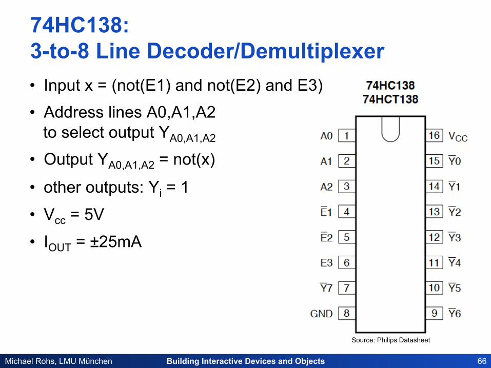
74HC138: 3-to-8 Line Decoder/Demultiplexer • Input x = (not(E1) and not(E2) and E3) • Address lines A0,A1,A2
to select output YA0,A1,A2
• Output YA0,A1,A2 = not(x)
• other outputs: Yi = 1
• Vcc = 5V
• IOUT = ±25mA
Source: Philips Datasheet
Building Interactive Devices and Objects 67 Michael Rohs, LMU München
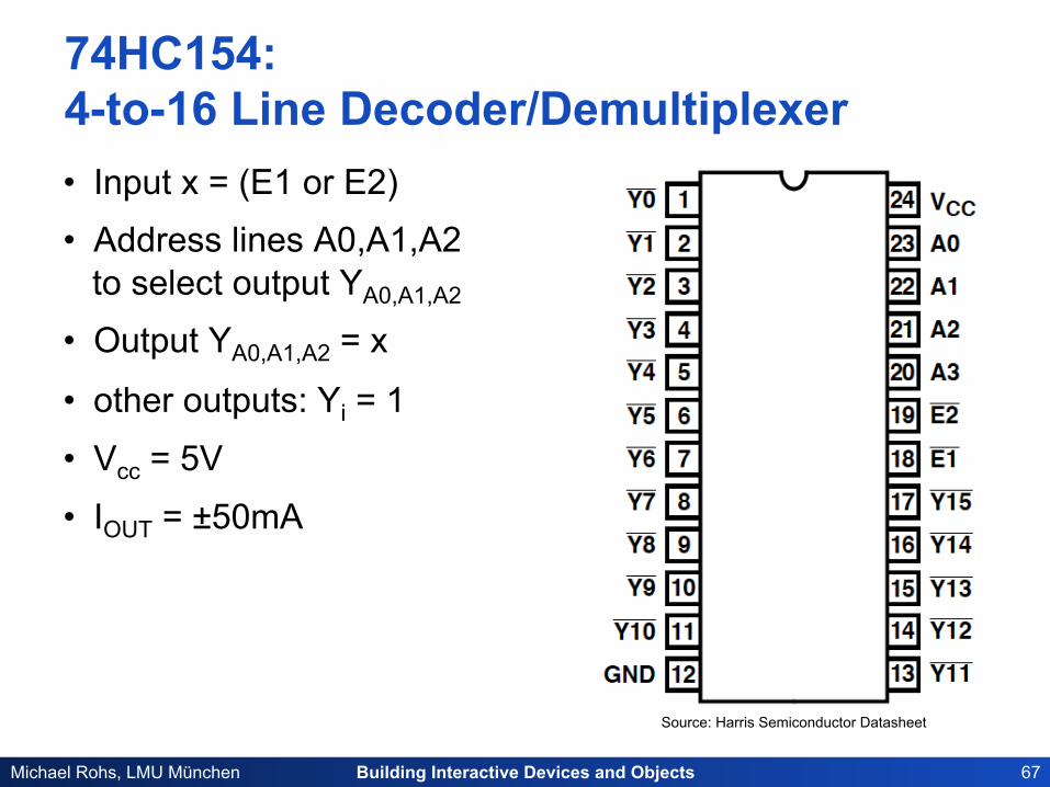
74HC154: 4-to-16 Line Decoder/Demultiplexer • Input x = (E1 or E2) • Address lines A0,A1,A2
to select output YA0,A1,A2
• Output YA0,A1,A2 = x
• other outputs: Yi = 1
• Vcc = 5V
• IOUT = ±50mA
Source: Harris Semiconductor Datasheet


![Interactive Video Tips: How to optimize Interactive Video for mobile devices [Week 5]](https://static.fdocuments.net/doc/165x107/554d129db4c905805d8b50b4/interactive-video-tips-how-to-optimize-interactive-video-for-mobile-devices-week-5.jpg)