BUILDING COMPONENTS 1. Sub structure 2. Super structure.
76
BUILDING COMPONENTS 1.Sub structure 2.Super structure
-
Upload
abigail-palmer -
Category
Documents
-
view
252 -
download
2
Transcript of BUILDING COMPONENTS 1. Sub structure 2. Super structure.

BUILDING COMPONENTS
1.Sub structure
2.Super structure

Sand Filling
Brick Masonry
Floor Finish
Foundation concrete
Ground Level
StepPlinth
Floor Concrete
Basement
Door
Lintel
Roof Slab
ParapetWeathering Course
COMPONENTS OF A BUILDING
Damp Proof Course
Foundation

FOUNDATIONFOUNDATION

Foundation is the part of the
structure which is in direct
contact with the ground to which
loads are transmitted.

A weak foundation destroys the work which is built upon
it.

Functions of foundationFunctions of foundationEven distribution of load
Reduction of load intensity
Reduction of differential settlement
Safety against sliding and overturning
Safety against undermining
Provide firm and level surface
Protection against soil movement

Requirements of a good Requirements of a good foundationfoundation
Constructed to sustain dead load and imposed
load and transmit them to underlying soil
Rigid-to avoid differential settlement
Taken to sufficient depth
Performance should not be affected due to any
unexpected future influence

Factors for the designFactors for the design
1. Bearing capacity of the soil
2. Settlement of foundations
Ultimate bearing capacity
Safe bearing capacity
Allowable bearing capacity
Uniform settlementDifferential
settlement

BEARING CAPACITY• Supporting power of soil without any failure• Depends on :
1. Properties of soil
2. Position of water table
3. Physical features of foundation like type, size & shape
• Ultimate Bearing Capacity : minimum gross pressure intensity at the
base of foundation that the soil fails in shear
• Net Ultimate Bearing Capacity : minimum net pressure intensity at which
the soil fails in shear
• Net safe bearing capacity : obtained by dividing the net ultimate bearing
capacity of the soil with a suitable factor of safety
• Safe bearing capacity : Maximum pressure the soil can carry safely
without the risk of shear failure

SETTLEMENT OF FOUNDATIONS
Uniform settlement is usually of little
consequence in a building, but differential settlement can cause severe structural damage.
No settlement Total settlement Differential settlement
Settlement of foundationsSettlement of foundations

Settlement of foundation means the sinking of foundation as a consequence of compression or deformation of the soil under the foundation
Equal Settlement :•The structures settles by uniform amount at each and every portion of the structure
Unequal Settlement:•The amount of settlement is different at different parts of the building
Causes of settlement:•Due to weight of the structure transmitted to the soil
•Due to increased load on the surrounding soil
•Due to excavation near the foundation
•Lowering of water table
•Vibrations from moving machineries
•Deterioration of concrete by the chemical action of soil, seawater etc…
•Due to mining and tunnelling operations
Causes of differential
settlement:•Non uniform load distribution on foundations
•Non uniformity of soil types
•Percolation of water
•Overlap and concentration of stresses due to presence of adjacent foun dations

Causes of foundation failureCauses of foundation failure
Unequal settlement of subsoil under the foundation
Unequal settlement of the masonryLateral movement of earthShrinkage of soil bed due to seasonal variation of
moisture contentThe penetration of the roots of treesAtmospheric actionLateral escape of the soil beneath the foundationHorizontal movement of the soil adjacent to the
structure

Types of FoundationsTypes of Foundations
Shallow Foundations D<=B
Deep Foundations D>B
D - Depth of foundation
B – Width of foundation

Shallow foundationsShallow foundations
Types of shallow foundations
Isolated or column footing
Wall or strip footing
Combined footing
Continuous footing
Cantilever footing
Raft or mat foundation

Isolated or column footingIsolated or column footing
When the load on the column is less, a spread is given under the column


Wall or strip footingWall or strip footingThe foundation which is provided through
out the length of a continuous structure is called strip footing.


Combined footingCombined footingWhen a foundation or footing is constructed
for two or more columns is called as combined footing
Two individual footings overlapWhen bearing capacity is lesswhen footings are constructednear boundaries of the plotTrapezoidal footing – when columnloads vary considerably


Continuous footingContinuous footing
A single continuous reinforced concrete
slab is provided as foundation for three or
more columns in a row. Continuous footing
is more suitable to prevent the differential
settlement in the structure and for the
safety against earthquake.

Continuous footingContinuous footing

Cantilever Footing (Strap)Cantilever Footing (Strap)Consists of an eccentric footing for the
exterior column and a concentric footing for the interior column.
A strap or a cantilever beam connects them.

Strap footingStrap footing


A raft foundation is a combined footing
which covers the entire area beneath a
structure and supports all the walls and
columns
Raft or mat foundation

Raft or mat foundationRaft or mat foundation

Mat foundationMat foundation

Raft or Mat FoundationRaft or Mat Foundation


Raft foundations are suitable when
1.The building loads are heavy
2.The allowable soil pressure is small
3.Individual footings would require more than half the
building area
4.In highly compressible soil
5.Weak spots and loose pockets in soil mass are
suspected
Deep FoundationDeep Foundation
The foundations having very large depth compared to width are called deep foundations
E.g. Pile foundations Well foundations


Pile FoundationPile Foundation
Piles are long slender members driven into ground or cast at the site. Pile foundations are common where the soil conditions are unfavorable for the use of shallow foundations

Suitability of pile foundationsSuitability of pile foundationsLoose foundation soil but hard strata is
available at a depth of 10-15 mHeavy dead and live loadsNear seashore or riverbed where scouring
action of water occursPosition of water table is likely to fluctuate
appreciablyCanals or deep drainage lines near by

Classification of PilesClassification of Piles
1. Method of load transfer2. Function or action3. Composition and material4. Installation

Classification based up on Classification based up on method of load transfermethod of load transfer1. End bearing Piles2. Friction Piles

End bearing pilesEnd bearing pilesEnd bearing piles-Used to transfer load
to a suitable bearing stratum

Friction pilesFriction pilesFriction Piles- used to transfer the loads
to a depth by friction along the surface area of the piles.

Classification based up on Classification based up on function or usefunction or use
1. Compaction Piles2. Tension or uplift piles3. Anchor Piles4. Fender Piles5. Sheet Piles

Compaction PilesCompaction Piles

Anchor Piles and Tension pilesAnchor Piles and Tension piles
Used to anchor structures subjected to hydrostatic pressure (against pilling or pushing forces)

Fender PilesFender Piles
To protect water front structures like docks, harbours etc… against impact from ships

Sheet PilesSheet Piles
Used to retain the sides of excavation, to prevent seepage below dams, to construct retaining walls etc.

Classification based up on Classification based up on material and compositionmaterial and composition
1. Timber Piles2. Steel Piles3. Concrete Piles4. Composite Piles

Timber PilesTimber Piles
Timber Piles perform well both in dry condition and in submerged condition

Steel PilesSteel Piles
Used to resist lateral or horizontal forces. More durable.
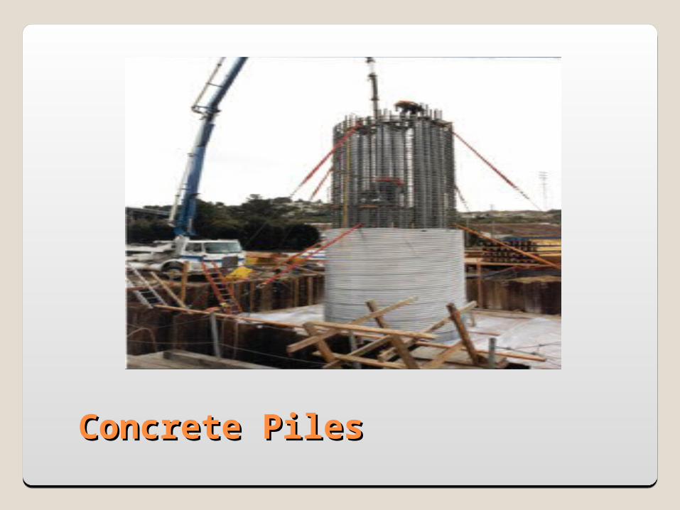
Concrete PilesConcrete Piles

Composite PilesComposite Piles
Used when part of the pile is submerged under water. Made up of concrete and steel

Classification based upon Classification based upon installationinstallation
1. Precast Piles2. Cast In Situ Piles

Precast PilesPrecast Piles

CAST IN SITU PILES•CASED CAST IN SITU PILES•UNCASED CAST INSITU PILES

Well FoundationsWell FoundationsA well foundation is a well type structure,
which built at the ground level and sunk into the soil at the required level.
The bridge pier will be resting on the top of the well foundation.
The bottom of the well is plugged with concrete.
The top is covered with a well cap which is a thick concrete slab

The bottom edge of the well foundation consists of a cutting edge. The different c/s adopted for well foundations are
1. Circular2. Twin circular3. Double D4. Dumb bell5. Twin hexagonal 6. Rectangular

Components of well foundationComponents of well foundation
Well curbCutting edgeSteiningBottom plugTop plugWell cap

WELL CAP
TOP PLUG
SAND OR SOIL FILLING
STEINING
WELL CURB
CUTTING EDGE
BOTTOM PLUG

Well curb Support the wt of the well
Cutting edge Sharp angle for cutting the soil without making it too weak
Steining Walls of the well
Bottom plug Concrete plug provided to balance the soil pressure
Top plug Concrete plug provided above the sand/soil filling
Well cap Serves as platform for the supporting members of the
superstructure


Laying the well curbConstruction of masonry in wall steini
ngWell sinkingCompletion of well
Well sinking operationsWell sinking operations

Soil excavation

Construction of well cap

To support the dynamic forces produced by the operation of the machine
To avoid large settlements at resonance, natural frequency of foundation should be different operating frequency of the machine
Machine foundationMachine foundation

Types of machinesImpact type
Presses, forge hammersReciprocating type
Compressors, enginesCentrifugal type
Motors, turbinesMiscellaneous types
Machine foundationMachine foundation

BLOCK TYPE BOX TYPE
WALL TYPE FRAMED TYPE


DETERMINATION OF
BEARING CAPACITY

Plate load testPlate load test
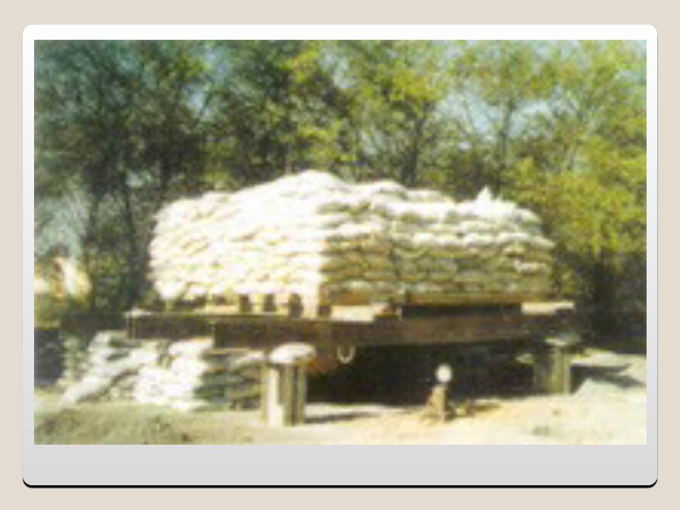
Plate load testPlate load test

PLATE LOAD TESTPLATE LOAD TEST It is a field test used to determine the ultimate
bearing capacity of soilA pit is dug up to the foundation levelA square plate of 300mm x 300mm & 25 mm is
placed at the centre of the pitA dial gauge is connected to the test plateNow weights in the form of sand bags are placed on
the platforms in equal increments. The test is continued till the failure occurs or the
plates settled by 25 mm whichever occurs earlierThe load settlement curve is then recorded.

Load v/s settlement graphLoad v/s settlement graph

Standard Penetration TestStandard Penetration Test

STANDARD PENETRATION TESTSTANDARD PENETRATION TESTTest is conducted in a bore hole 50 to 150 mm in
diameterSplit spoon sampler (pipe-like weight) is driven
into the ground by a weight of 65 kg weight is repeatedly raised and dropped a
distance of 750 mm to drive in sampler number of blows required to drive the sampler
for a penetration of 300mm is recorded The number of blows is known as penetration
number (N Value)There are empirical charts from which the
bearing capacity can be calculated based up on the N Value

Methods for improving Bearing Methods for improving Bearing CapacityCapacity
CompactionDrainageVibratory methodsChemical stabilisationGroutingGeotextiles