
Building A Boeing 737 Yoke · PDF file [email protected] updated Dec 2008 Mk3 Yoke Building A...
14
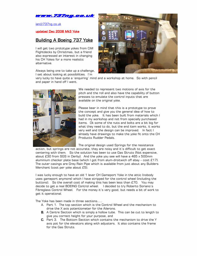
www.737ng.co.uk www.737ng.co.uk www.737ng.co.uk www.737ng.co.uk [email protected] updated Dec 2008 Mk3 Yoke updated Dec 2008 Mk3 Yoke updated Dec 2008 Mk3 Yoke updated Dec 2008 Mk3 Yoke Building A Boeing 737 Yoke Building A Boeing 737 Yoke Building A Boeing 737 Yoke Building A Boeing 737 Yoke I will get two prototype yokes from CiM Flightdecks by Christmas, but a friend also expressed an interest in changing his CH Yokes for a more realistic alternative. Always being one to take up a challenge, I set about looking at possibilities. I’m very lucky to have quite a ‘enquiring’ mind and a workshop at home. So with pencil and paper in hand off I went. We needed to represent two motions of axis for the pitch and the roll and also have the capability of button presses to emulate the control inputs that are available on the original yoke. Please bear in mind that this is a prototype to prove the concept and give you the general idea of how to build the yoke. It has been built from materials which I had in my workshop and not from specially purchased items. Ok some of the nuts and bolts are a bit big for what they need to do, but the end item works, it works very well and the design can be improved. In fact I already have drawings to make the yoke fit onto the CH Products Rudder Pedals. The original design used Springs for the resistance action, but springs are not accurate, they are noisy and it’s difficult to get exact centering with them. So the solution has been to use Gas Struts (Not expensive, about £30 from SGS in Derby). And the yoke you see will have a 465 x 500mm aluminium checker plate base (which I got from alum-droitwich off ebay – cost £17). The outer casings are Grey Rain Pipe which is available from just about any Builders Merchant (cost per yoke about £5). I was lucky enough to have an old 1 lever CH Gameport Yoke in the attic (nobody uses gameport anymore) which I have stripped for the control wheel (including the buttons). So the overall cost of making this has been less than £70. You may decide to get a real BOEING Control wheel. I decided to try Roberto Soriano’s Fibreglass Control Wheel. For the money it’s very good, but needs a bit of work to get it operational. The Yoke has been made in three sections….. A. Part 1. The top section which is the Control Wheel and the mechanism to drive the X axis potentiometer for the Ailerons. B. B. B. B. A Centre Section which is simply a hollow tube. This can be cut to length to give you correct height for your purpose, and C. C. C. C. Part 3. The Bottom Section which contains the mechanism to drive the Y axis pot for the elevators along with adjusters. It also contains the frame for the Gas Struts.
Transcript of Building A Boeing 737 Yoke · PDF file [email protected] updated Dec 2008 Mk3 Yoke Building A...
www.737ng.co.ukwww.737ng.co.ukwww.737ng.co.ukwww.737ng.co.uk [email protected] updated Dec 2008 Mk3 Yokeupdated Dec 2008 Mk3 Yokeupdated Dec 2008 Mk3 Yokeupdated Dec 2008 Mk3 Yoke
Building A Boeing 737 YokeBuilding A Boeing 737 YokeBuilding A Boeing 737 YokeBuilding A Boeing 737 Yoke
I will get two prototype yokes from CiM Flightdecks by Christmas, but a friend also expressed an interest in changing his CH Yokes for a more realistic alternative.
Always being one to take up a challenge, I set about looking at possibilities. I’m very lucky to have quite a ‘enquiring’ mind and a workshop at home. So with pencil and paper in hand off I went.
We needed to represent two motions of axis for the
pitch and the roll and also have the capability of button presses to emulate the control inputs that are available on the original yoke. Please bear in mind that this is a prototype to prove the concept and give you the general idea of how to
build the yoke. It has been built from materials which I had in my workshop and not from specially purchased items. Ok some of the nuts and bolts are a bit big for what they need to do, but the end item works, it works very well and the design can be improved. In fact I
already have drawings to make the yoke fit onto the CH Products Rudder Pedals. The original design used Springs for the resistance
action, but springs are not accurate, they are noisy and it’s difficult to get exact centering with them. So the solution has been to use Gas Struts (Not expensive,
about £30 from SGS in Derby). And the yoke you see will have a 465 x 500mm aluminium checker plate base (which I got from alum-droitwich off ebay – cost £17). The outer casings are Grey Rain Pipe which is available from just about any Builders Merchant (cost per yoke about £5). I was lucky enough to have an old 1 lever CH Gameport Yoke in the attic (nobody
uses gameport anymore) which I have stripped for the control wheel (including the buttons). So the overall cost of making this has been less than £70. You may decide to get a real BOEING Control wheel. I decided to try Roberto Soriano’s Fibreglass Control Wheel. For the money it’s very good, but needs a bit of work to get it operational.
The Yoke has been made in three sections….. A. Part 1. The top section which is the Control Wheel and the mechanism to
drive the X axis potentiometer for the Ailerons. B.B.B.B. A Centre Section which is simply a hollow tube. This can be cut to length to
give you correct height for your purpose, and C.C.C.C. Part 3. The Bottom Section which contains the mechanism to drive the Y
axis pot for the elevators along with adjusters. It also contains the frame for the Gas Struts.
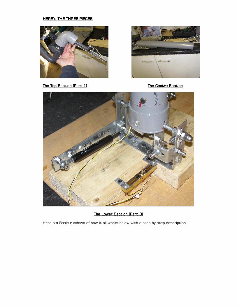
HERE’s THE THREE PIECESHERE’s THE THREE PIECESHERE’s THE THREE PIECESHERE’s THE THREE PIECES
The Top Section (Part 1)The Top Section (Part 1)The Top Section (Part 1)The Top Section (Part 1) The Centre SectionThe Centre SectionThe Centre SectionThe Centre Section
The Lower Section (Part 3)The Lower Section (Part 3)The Lower Section (Part 3)The Lower Section (Part 3)
Here’s a Basic rundown of how it all works below with a step by step description.
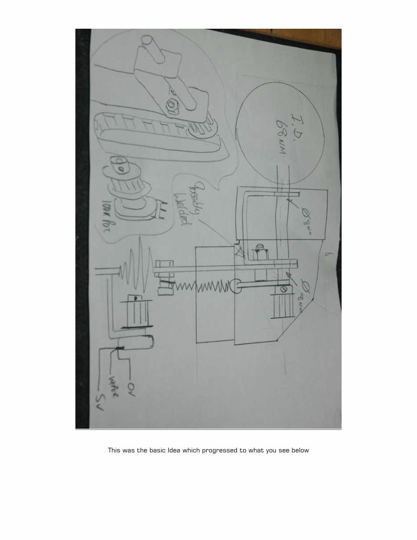
This was the basic Idea which progressed to what you see below

Part 1 ROLL (AILERON) ACTION Part 1 ROLL (AILERON) ACTION Part 1 ROLL (AILERON) ACTION Part 1 ROLL (AILERON) ACTION
Take a look at the above illustration. It’s pretty simple if you study it. But basically, this is how it works. Shaft B rotates in two bushes in Frame C. On one end of the shaft is bolted plate A (this is what you fix your control wheel to). On the other end of the shaft is attached a toothed pulley (D). The pulley prevents the shaft from being pulled forward and I have attached two locknuts inside the rear top upright plate of frame C to stop the shaft from being pushed back. It then follows that if you rotate plate A, shaft B transmits that motion to Pulley D. A second pulley is attached to the potentiometer F which is fitted to the lower bracket on frame C. The two pulleys are joined by a toothed belt which then transmits the rotational motion of upper pulley D to lower pulley D and consequently, the pot. In my prototype, I have also included an adjuster so I can get the drive belt to sit
nice on the pulleys without any tension which may damage the potentiometer. That’s how the Ailerons will be driven. Here’s some photo’s to give you a better idea.
Part 2 RefinementsPart 2 RefinementsPart 2 RefinementsPart 2 Refinements
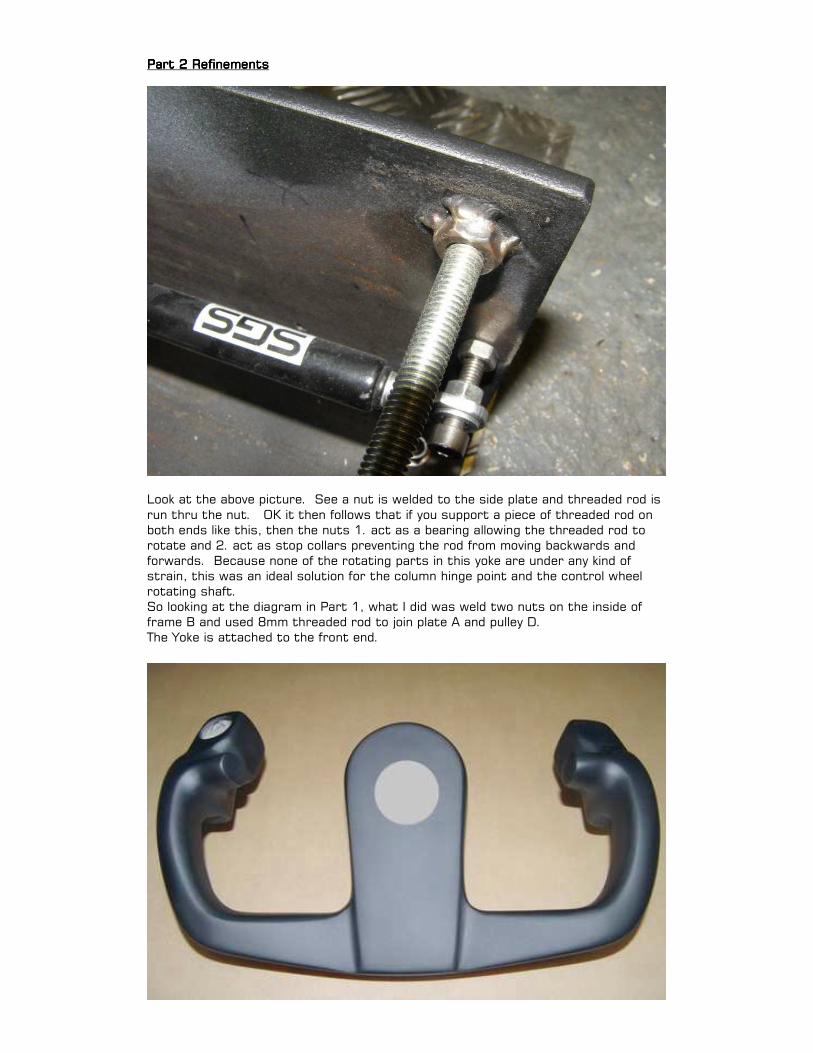
Look at the above picture. See a nut is welded to the side plate and threaded rod is
run thru the nut. OK it then follows that if you support a piece of threaded rod on both ends like this, then the nuts 1. act as a bearing allowing the threaded rod to rotate and 2. act as stop collars preventing the rod from moving backwards and forwards. Because none of the rotating parts in this yoke are under any kind of strain, this was an ideal solution for the column hinge point and the control wheel rotating shaft. So looking at the diagram in Part 1, what I did was weld two nuts on the inside of frame B and used 8mm threaded rod to join plate A and pulley D. The Yoke is attached to the front end.

Above is a picture of Roberto Soriano’s yoke and below is a picture of the Boss I made to replace plate A in Part 1. Now in order to get the yoke right upto the column, the nut you see welded to the plate will have to fit inside the yoke. Look again at the picture of the Control wheel and you will see a Grey area in the centre. I used a 32mm hole cutter to remove this piece from the front (it’s going to be hidden by the Engravity Chart Plate). This
allowed me access to the inside of the yoke to prepare my fixings and also to fit a locknut to secure the position of the control wheel on the shaft. The four smaller holes will allow me to use 4mm nuts and bolts to secure the boss to the Control wheel itself. The larger hole above the nut will carry the switch leads duly wrapped in PVC cable wrap to protect them.
Remembering that we are using a Fibreglass Moulded Yoke here. Fibreglass is
notoriously brittle and unforgiving to shock or stress before cracking or breaking. I built up the rear face of the yoke with epoxy filler to about 6mm thick to give it extra strength. I have also placed some 2mm rubber gaskets between the glassfibre and all metal items. It’s all fitted together well and I’m confident that it will now work without causing problems. Ok, that’s got the top of the Yoke working, lets move on to the bottom. The refinements to the bottom are further down.

PART 3 PART 3 PART 3 PART 3 –––– THE PITCH (ELEVATOR) ACTION THE PITCH (ELEVATOR) ACTION THE PITCH (ELEVATOR) ACTION THE PITCH (ELEVATOR) ACTION
The Down Pipe A rocks on centre shaft B. Also attached to centre shaft B, are two fulcrum levers C & D. From fulcrum D, a drive rod E is attached to potentiometer F. Attached to fulcrum C are two Gas Struts (H) (50 newton force, 60mm travel) to give the yoke a ‘positive feel’. The forward/backward travel can be limited by the adjusters G. Remembering in a neutral position, the Boeing Yoke is not upright, but has a slightly forward lean.
I’ve used 60mm travel Gas Struts rated at 50n. These were obtained from www.sgs-engineering.com in DERBY, England. If I ever have to do this again, I would probably go for a higher force strut. 50n is good, but if you want to grunt when you use the yoke, use a higher rated strut. So remembering that at the centre position, you will need the struts also in their
centre. This will give you ‘push and pull’ pressure as you use the yoke in Pitch. The Next StThe Next StThe Next StThe Next Step.ep.ep.ep. Given that the concept is correct and that the idea actually works, I am now going to refine the design. The top part is fine, all it needs is tidying up. The bottom
assembly will be modified so that all the mechanism fits onto the centre block. This will allow the unit to be mated up with the CH Rudder Pedals for a more realistic ‘look and positioning’.

So off to the workshop, hacksaw in hand :o) here’s he result.
To mate up to the CH Rudders, the maximum width you can use (including any cover) is 90mm. This is the distance between the pedals. For a comfortable fit, the yoke column must fit up against the back of the Rudder Unit. So it was necessary to move all the mechanics (apart from the forward Gas Strut) to behind the column.
Additionally, given that top of the column is 80cms above floor level, stability was also a problem. So I changed the original plywood base for an aluminium checker plate panel. 80% of the problem is cured. When I am satisfied that the operation and reliability is 100%, the unit will be bolted to the floor.

Here’s a look at the New Mechanism Here’s a look at the New Mechanism Here’s a look at the New Mechanism Here’s a look at the New Mechanism I’ve used some multi pin connectors for the three leads per potentiometer and ribbon cable with an IDC plug and socket for the buttons, so that removal is quick
and easy.
So It’s Off To Test ItSo It’s Off To Test ItSo It’s Off To Test ItSo It’s Off To Test It No two cockpits are the same setup and no two items will use the same interface/controller/joystick card. So you will have to calibrate and configure on your own I’m afraid.
I then put the unit in my pit to find out what ‘adjustments’ have to be made. Not only does it have to look right it also has to feel and control properly. So let’s play with the control assignments and ‘feel forces’ to get it right before making the cover for the mechanism

Fitting a Spring to Give Feel On the Roll AxisFitting a Spring to Give Feel On the Roll AxisFitting a Spring to Give Feel On the Roll AxisFitting a Spring to Give Feel On the Roll Axis If you look at my original drawing, you will see that my first idea was to fit a lug behind the upper pulley and attach a spring to that lug. But when I started to look at assembling the yoke, it transpired that 1. there was not enough free space to do this and 2. I had contact with the belt.
So a new approach was needed. Here’s how it panned out.
On the upper pulley D, I welded a small arm shown in the above shots. A Dome headed 6mm allen bolt is passed thru the hole in the end and bolted in place. The reason for the 5mm kink is so that the arm/bolt/spring is kept clear of the drive belt. This pulley is then fixed to the centre shaft B and one end of the spring is seated on the 6mm bolt. A second bolt is placed in the downleg of the
assembly and the other end of the spring is fixed there as in the shot below. Now as the roll axis is moved, the spring action gives feel and brings the yoke back to centre when at rest. The added bonus is that the welded leg acts as a limiter to the range of rotation by contacting the wall of the upright tube when rotated. By filing off the red areas in the upper left shot, I have the control wheel rotating 45 degrees left and right of centre. Makes calibration a dawdle and accurate. Very happy now with the result. It’s as good as bought one :o)

Part 4 Base refinementsPart 4 Base refinementsPart 4 Base refinementsPart 4 Base refinements
If you look on page 1 at the picture of the original prototype and now look at the (almost) complete article, there’s a world of difference. Please remember that the
prototype was made from
‘scrap’ strip metal and was only to prove the concept. What you see in Part 3 of this document is
purely now to explain the mechanics of the idea. From
this prototype all the dimensions
were calculated. A proper box has been made from 5mm mild steel plate and the mechanics have now been enclosed. All
painted up it looks very good and
professional.
What about a realistic control wheel for the top then. This one is made by Roberto Soriano from
El Salvador. Despatched in 4 days and here a week later. Price (Jan 2008) was US$120 + $35
shipping. e-mail
it’s a fibreglass moulded yoke which is hollow and as soon as I
have fixed it all, I’ll fill it with expanding foam to give it a solid feel/sound.

So far, so good. But I was looking to make a better finished product for inclusion in the cockpit. So onto Mark3. Using the concepts learnt building the previous versions, it was simple to re-work the design into the FINAL version.
Part 5 Part 5 Part 5 Part 5 –––– The Final Version. The Final Version. The Final Version. The Final Version.

Whilst the top of the yoke remains unchanged from the original idea, I was not completely satisfied with the appearance of the Mk2. So having ‘borrowed’ an idea from a colleague I decided to enclose the mechanism completely. This meant that bearing in mind that the rudder pedals have to be a good fit against the back of the casing for a ‘comfortable’ control position, this is how it was done. I also removed the Glassfibre Yoke, because it was not substantial enough and started to
crack. I replaced it with one from Said in Holland, much better quality and feel. Remember that the gas struts have to have an action on the column and that both struts have to be the same distance from the centre point to achieve an equal feel. Here’s the new design……….

Both gas struts have been placed to the rear of the unit. They are fixed to an anchor point at the back and to a fulcrum lever (red) fitted to the centre shaft (black +). The distance A
from the centre shaft to the front fixing of the gas strut both up and down must be the same to give you a balance. A second fulcrum drives the potentiometer. Distance B is calculated to use as much of the travel of the potentiometer as possible. As usual, thanks for your interest and as I always say, if you know a better way to
do it, tell me, DON’T KEEP IT TO YOURSELF :o) Regards … Ian P.Sissons OSWESTRY, England December 4th 2008


