Builder’s Log – Helicycle N750G · Builder’s Log – Helicycle N750G ... about where it will...
10
Builder’s Log – Helicycle N750G Juan Rivera 281 I sanded down the exterior area of the tank and cleaned it with isopropyl alcohol, then cleaned the brass fitting with acetone. I applied Bondit B-4811, a two-part, adhesive that is designed to bond dissimilar materials such as polyethylene and metal. I hope this works because it’s very expensive. To make the bond as sturdy as possible I ran the fittings in almost all the way so I could run the epoxy from the body of the fitting to the fuel tank exterior and not depend on the adhesive bond in the threads alone. That material always tends to be squeezed out as the fittings are installed. The epoxy will be cured in 24 hours and I’ll see how things look. By the way, the brass fitting at the bottom is a spring-loaded drain. By pushing up and twisting I can drain a small amount of fuel from the bottom of the tanks to look for water and foreign material during my pre-flight checks. I’m inching closer to final installation of the seat pan and instrument panel… Here’s the final configuration. The ‘T’ is about three-quarters of an inch in front of the tubes, and that’s about where it will end up when it’s tie-wrapped to the cabin. The remaining hose fitting on the left of the picture connects to the auxiliary tank.
-
Upload
nguyenxuyen -
Category
Documents
-
view
229 -
download
0
Transcript of Builder’s Log – Helicycle N750G · Builder’s Log – Helicycle N750G ... about where it will...

Builder’s Log – Helicycle N750G
Juan Rivera 281
I sanded down the exterior area of the tank and cleaned it with isopropyl alcohol, then cleaned the brass fitting with acetone. I applied Bondit B-4811, a two-part, adhesive that is designed to bond dissimilar materials such as polyethylene and metal. I hope this works because it’s very expensive. To make the bond as sturdy as possible I ran the fittings in almost all the way so I could run the epoxy from the body of the fitting to the fuel tank exterior and not depend on the adhesive bond in the threads alone. That material always tends to be squeezed out as the fittings are installed. The epoxy will be cured in 24 hours and I’ll see how things look. By the way, the brass fitting at the bottom is a spring-loaded drain. By pushing up and twisting I can drain a small amount of fuel from the bottom of the tanks to look for water and foreign material during my pre-flight checks. I’m inching closer to final installation of the seat pan and instrument panel…
Here’s the final configuration. The ‘T’ is about three-quarters of an inch in front of the tubes, and that’s about where it will end up when it’s tie-wrapped to the cabin. The remaining hose fitting on the left of the picture connects to the auxiliary tank.
Builder’s Log – Helicycle N750G
Juan Rivera 282
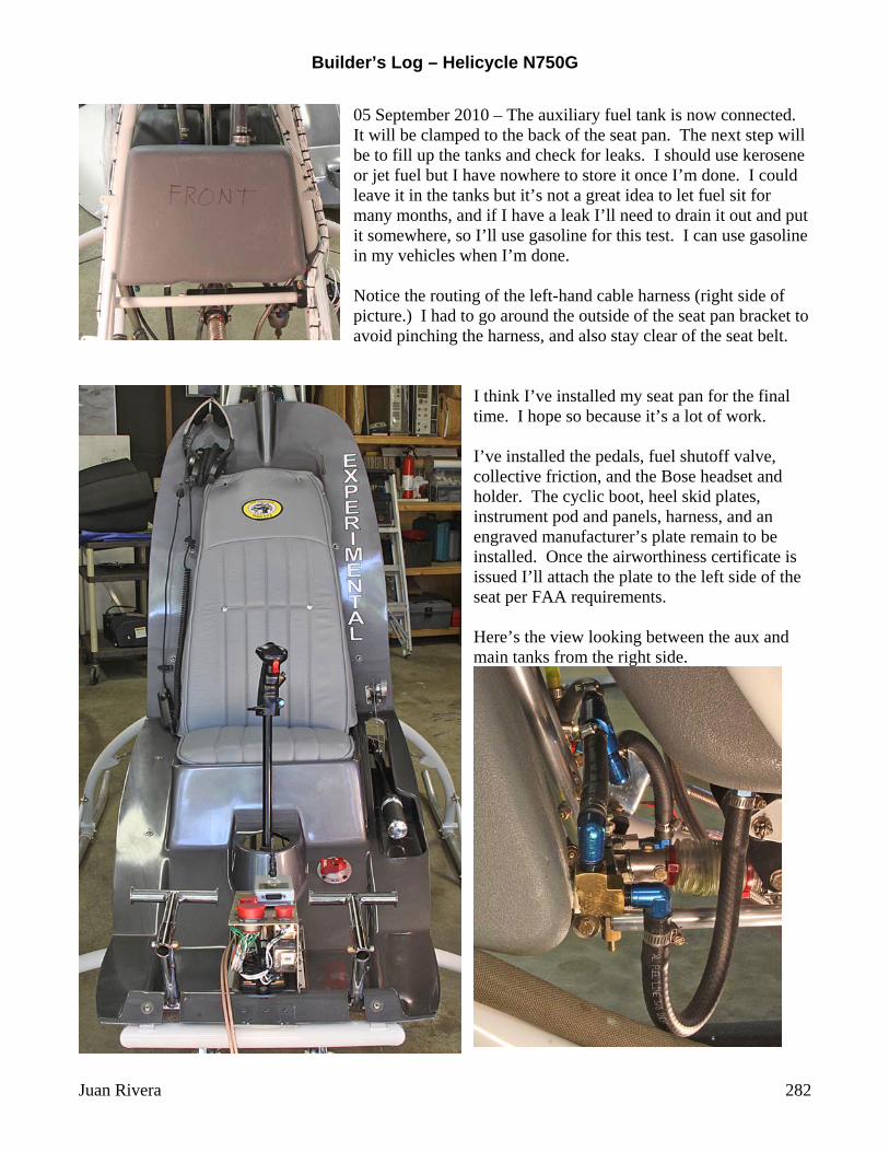
05 September 2010 – The auxiliary fuel tank is now connected. It will be clamped to the back of the seat pan. The next step will be to fill up the tanks and check for leaks. I should use kerosene or jet fuel but I have nowhere to store it once I’m done. I could leave it in the tanks but it’s not a great idea to let fuel sit for many months, and if I have a leak I’ll need to drain it out and put it somewhere, so I’ll use gasoline for this test. I can use gasoline in my vehicles when I’m done. Notice the routing of the left-hand cable harness (right side of picture.) I had to go around the outside of the seat pan bracket to avoid pinching the harness, and also stay clear of the seat belt.
I think I’ve installed my seat pan for the final time. I hope so because it’s a lot of work. I’ve installed the pedals, fuel shutoff valve, collective friction, and the Bose headset and holder. The cyclic boot, heel skid plates, instrument pod and panels, harness, and an engraved manufacturer’s plate remain to be installed. Once the airworthiness certificate is issued I’ll attach the plate to the left side of the seat per FAA requirements. Here’s the view looking between the aux and main tanks from the right side.
Builder’s Log – Helicycle N750G
Juan Rivera 283
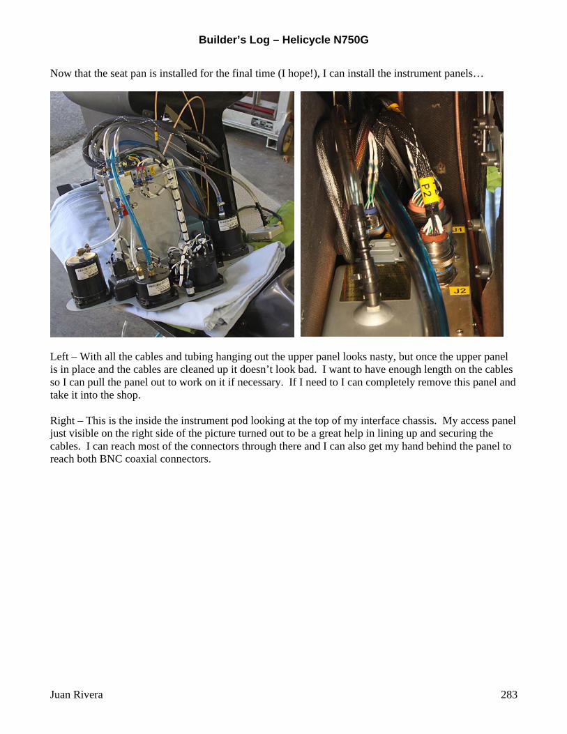
Now that the seat pan is installed for the final time (I hope!), I can install the instrument panels…
Left – With all the cables and tubing hanging out the upper panel looks nasty, but once the upper panel is in place and the cables are cleaned up it doesn’t look bad. I want to have enough length on the cables so I can pull the panel out to work on it if necessary. If I need to I can completely remove this panel and take it into the shop. Right – This is the inside the instrument pod looking at the top of my interface chassis. My access panel just visible on the right side of the picture turned out to be a great help in lining up and securing the cables. I can reach most of the connectors through there and I can also get my hand behind the panel to reach both BNC coaxial connectors.
Builder’s Log – Helicycle N750G
Juan Rivera 284
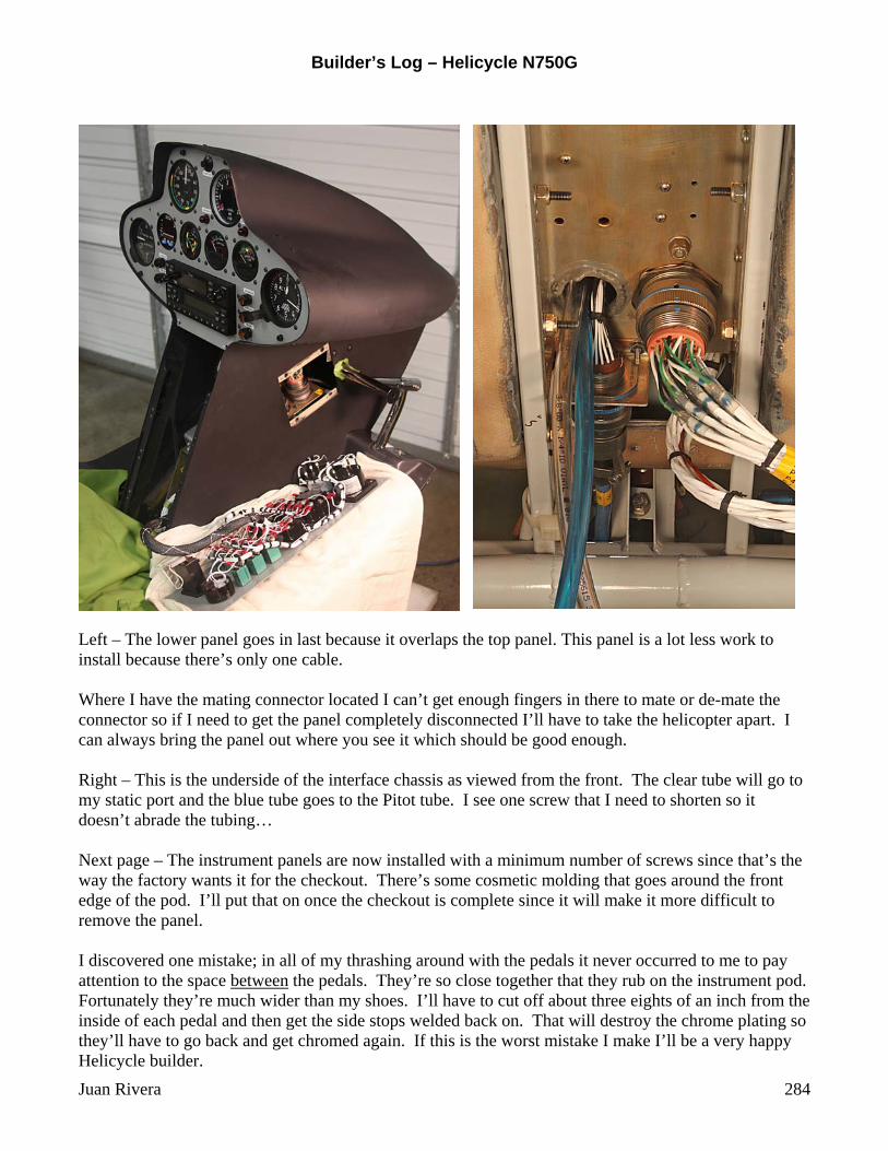
Left – The lower panel goes in last because it overlaps the top panel. This panel is a lot less work to install because there’s only one cable. Where I have the mating connector located I can’t get enough fingers in there to mate or de-mate the connector so if I need to get the panel completely disconnected I’ll have to take the helicopter apart. I can always bring the panel out where you see it which should be good enough. Right – This is the underside of the interface chassis as viewed from the front. The clear tube will go to my static port and the blue tube goes to the Pitot tube. I see one screw that I need to shorten so it doesn’t abrade the tubing… Next page – The instrument panels are now installed with a minimum number of screws since that’s the way the factory wants it for the checkout. There’s some cosmetic molding that goes around the front edge of the pod. I’ll put that on once the checkout is complete since it will make it more difficult to remove the panel. I discovered one mistake; in all of my thrashing around with the pedals it never occurred to me to pay attention to the space between the pedals. They’re so close together that they rub on the instrument pod. Fortunately they’re much wider than my shoes. I’ll have to cut off about three eights of an inch from the inside of each pedal and then get the side stops welded back on. That will destroy the chrome plating so they’ll have to go back and get chromed again. If this is the worst mistake I make I’ll be a very happy Helicycle builder.

Builder’s Log – Helicycle N750G
Juan Rivera 285

Builder’s Log – Helicycle N750G
Juan Rivera 286
Saturday 11 September – On page 276 I bonded the lower fuel tank brass fittings to the bottom of the polyethylene main tanks using Bondit B-4811, a two-part adhesive especially blended to bond dissimilar materials. I decided to do a pull test on a scrap, so I bonded a brass fitting to an old tool box. Between the pictures on page 276 and this one you get a good idea of the concept of surface energy. A good example of low surface energy is the hood of a highly polished automobile. Water beads on the surface and doesn’t wet. When the water spreads across the surface smoothly then the surface has high surface energy. At the molecular level the surface energy is what causes the adhesive to bond to the base material. Brass has
high surface energy, and notice how the adhesive flows out to a very thin concave meniscus. There’s a lot of attraction between the adhesive and the brass. The bond to the polyethylene looks slightly convex, but still encouraging. Update: After a two-day cure it took 25 pounds of force to pull the fitting loose. The bond to the polyethylene failed and the adhesive came off with the fitting. That’s what I expected. Not bad!
I’ve also been reinforcing the bottom of the cabin door lip area on the left side. Hap warned me that people tend to put all their weight on this lip while getting in and out of the cabin. The entire cabin, including the door lips, are very thin fiberglass and wouldn’t hold up well to heavy forces. I started with long stranded fiberglass patching material and then went over that with body filler. Once I get that blended in went over it with glazing putty. I also took this opportunity to scoop out a section of the lip where my knuckles will be when I raise the collective. Here’s a closer look from the side. You can see where I’ve scooped out the lip for more clearance near the collective throttle. Now that the left side is done I’ll do the same on the right side. That way the cabin won’t get busted up when people use the door lips to lift themselves up and get adjusted in the seat. I can’t imagine actually letting anyone sit in my baby, but I suppose it’s possible…

Builder’s Log – Helicycle N750G
Juan Rivera 287
The foot plates are installed. I made them out of .031” stainless and polished them using three grades of rouge. I secured them using sticky-back Velcro so I can remove them as needed. The only tricky part is dealing with the seat pan bump on the left side (white arrow.) I chose to hammer out a matching bump rather than cut around it. It was easy.
I don’t have much left to do to finish off the inside of the cabin:
Install cyclic boot (in the mail) Chrome and install modified foot pedals (in the mail) Paint interior with Zolatone (waiting to decide on camera mount rod – see pg. 275) Install restraint system (on order and due in one week) Finish off door hinges and mount to cabin
Builder’s Log – Helicycle N750G
Juan Rivera 288
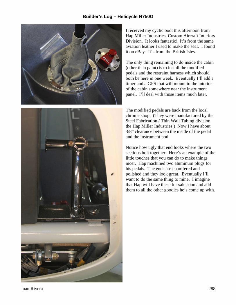
I received my cyclic boot this afternoon from Hap Miller Industries, Custom Aircraft Interiors Division. It looks fantastic! It’s from the same aviation leather I used to make the seat. I found it on eBay. It’s from the British Isles. The only thing remaining to do inside the cabin (other than paint) is to install the modified pedals and the restraint harness which should both be here in one week. Eventually I’ll add a timer and a GPS that will mount to the interior of the cabin somewhere near the instrument panel. I’ll deal with those items much later. The modified pedals are back from the local chrome shop. (They were manufactured by the Steel Fabrication / Thin Wall Tubing division the Hap Miller Industries.) Now I have about 3/8” clearance between the inside of the pedal and the instrument pod. Notice how ugly that end looks where the two sections bolt together. Here’s an example of the little touches that you can do to make things nicer. Hap machined two aluminum plugs for his pedals. The ends are chamfered and polished and they look great. Eventually I’ll want to do the same thing to mine. I imagine that Hap will have these for sale soon and add them to all the other goodies he’s come up with.

Builder’s Log – Helicycle N750G
Juan Rivera 289
Hap Miller mentioned that I should install striker plates on the left door lips so I don’t damage my paint. The top and bottom ones are extremely simple because the area is essentially flat. The one in the front is an entirely different situation because it is in a curved area. I decided to give it a try using .031” stainless steel. I started by cutting sure rectangular pieces that were about 1”x2”. The first step was to make a lip for the outside of the plate so the pin will ride up over the lip and not hit the paint. That part didn’t seem too hard.
I used a scrap of ¼” stock to act as a guide, dropped it into my vise, clamped it down, and removed the guide.
Then I used the guide to roll the piece over the jaw protector and finished it off with a few taps of my hard rubber hammer. That left me with the lip you see in the center picture. Next I made myself a form by tracing the curve on the door onto a piece of Delrin I had in my junk box. I milled out the general shape and then cleaned it up using a half-round hand file.
The next step was to place the flat piece in the form and gently tap away at it until it took the shape I wanted. Now comes the tricky part… As the piece takes the shape of the large radius it tends to straighten the lip. I found that I could clamp the piece against the form by squashing it against my largest fire extinguisher. Then I was able to go along the lip and tap it back into the shape I wanted.
Builder’s Log – Helicycle N750G
Juan Rivera 290
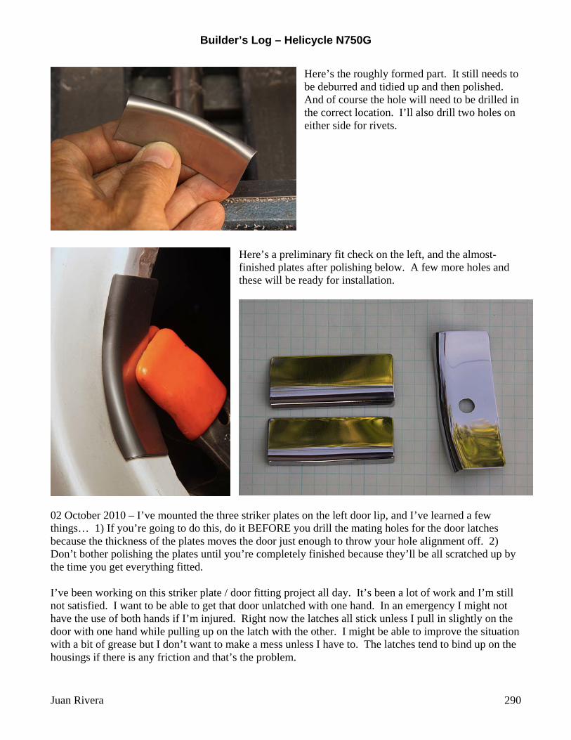
Here’s the roughly formed part. It still needs to be deburred and tidied up and then polished. And of course the hole will need to be drilled in the correct location. I’ll also drill two holes on either side for rivets.
Here’s a preliminary fit check on the left, and the almost-finished plates after polishing below. A few more holes and these will be ready for installation.
02 October 2010 – I’ve mounted the three striker plates on the left door lip, and I’ve learned a few things… 1) If you’re going to do this, do it BEFORE you drill the mating holes for the door latches because the thickness of the plates moves the door just enough to throw your hole alignment off. 2) Don’t bother polishing the plates until you’re completely finished because they’ll be all scratched up by the time you get everything fitted. I’ve been working on this striker plate / door fitting project all day. It’s been a lot of work and I’m still not satisfied. I want to be able to get that door unlatched with one hand. In an emergency I might not have the use of both hands if I’m injured. Right now the latches all stick unless I pull in slightly on the door with one hand while pulling up on the latch with the other. I might be able to improve the situation with a bit of grease but I don’t want to make a mess unless I have to. The latches tend to bind up on the housings if there is any friction and that’s the problem.