Build Your Own Clone BOSS DS-1 Relay Bypass Switch...
21
Build Your Own Clone BOSS DS-1 Relay Bypass Switch Installation Guide Click here for instructions on building the relay bypass kit: http://byocelectronics.com/relaybypassinstructions.pdf
Transcript of Build Your Own Clone BOSS DS-1 Relay Bypass Switch...

BuildYourOwnCloneBOSSDS-1RelayBypassSwitch
InstallationGuide
Clickhereforinstructionsonbuildingtherelaybypasskit:http://byocelectronics.com/relaybypassinstructions.pdf
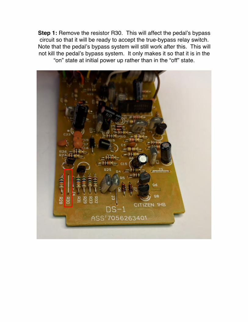
Step 1: Remove the resistor R30. This will affect the pedal’s bypass circuit so that it will be ready to accept the true-bypass relay switch.
Note that the pedal’s bypass system will still work after this. This will not kill the pedal’s bypass system. It only makes it so that it is in the
“on” state at initial power up rather than in the “off” state.
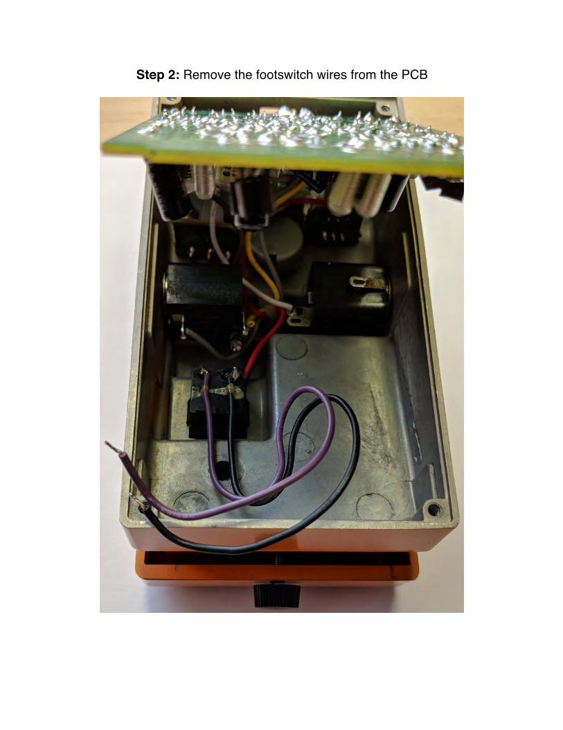
Step 2: Remove the footswitch wires from the PCB
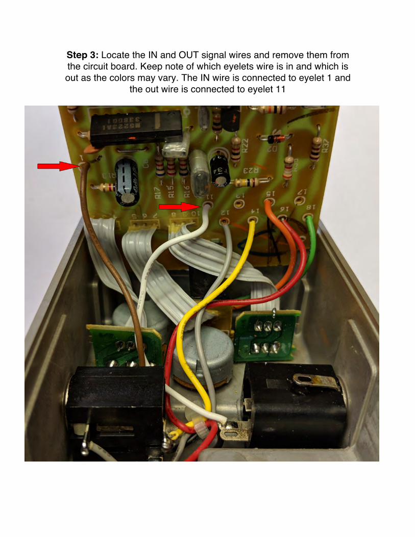
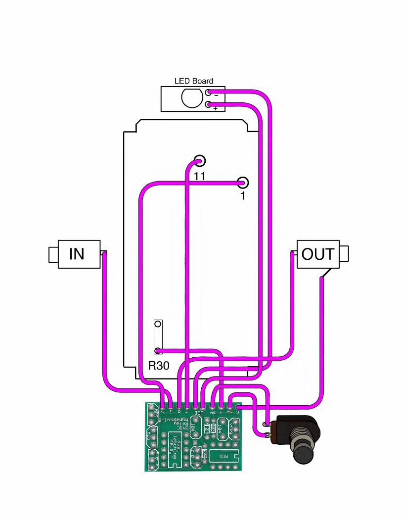
Step 3: Locate the IN and OUT signal wires and remove them from the circuit board. Keep note of which eyelets wire is in and which is out as the colors may vary. The IN wire is connected to eyelet 1 and
the out wire is connected to eyelet 11


Step 4: Remove the LED circuit board from the pedal by removing the screw that holds it in place.

Step 4a: The green and orange LED wires need to be replaced because they are too short to be reused, so removed them entirely
from both the main PCB and the LED PCB. Be sure to make a note of which of the two holes on the LED PCB are positive
(orange) and negative (green)
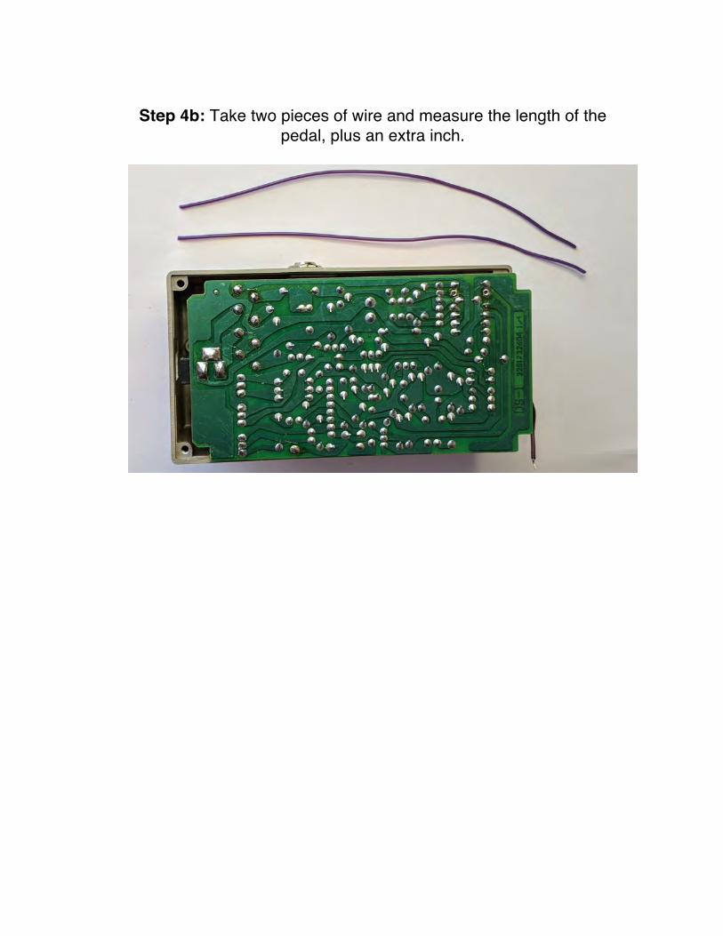
Step 4b: Take two pieces of wire and measure the length of the
pedal, plus an extra inch.
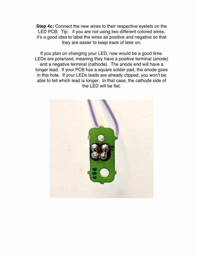
Step 4c: Connect the new wires to their respective eyelets on the LED PCB. Tip: if you are not using two different colored wires,
it’s a good idea to label the wires as positive and negative so that they are easier to keep track of later on.
If you plan on changing your LED, now would be a good time.
LEDs are polarized, meaning they have a positive terminal (anode) and a negative terminal (cathode). The anode end will have a
longer lead. If your PCB has a square solder pad, the anode goes in this hole. If your LEDs leads are already clipped, you won’t be able to tell which lead is longer. In that case, the cathode side of
the LED will be flat.
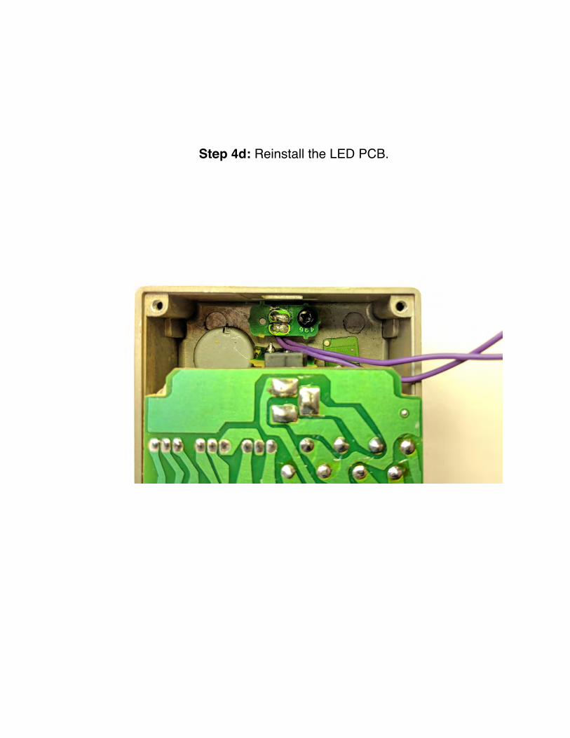
Step 4d: Reinstall the LED PCB.

Step 5: Attach a wire to a ground location. We are using the unused ground lug on the output jack.

Step 6: Attach a wire to the side of R30 that connects to +9v. This will be referred to as “+”.
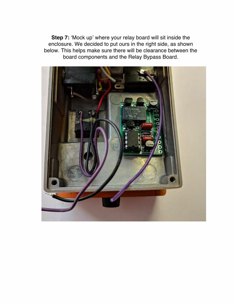
Step 7: ‘Mock up’ where your relay board will sit inside the
enclosure. We decided to put ours in the right side, as shown below. This helps make sure there will be clearance between the
board components and the Relay Bypass Board.

Step 8: Connect the ground (G), 9v (+), and switch wires (sw) to
the Relay Bypass Board. When attaching the switch wires, it doesn’t matter which eyelets they go into as long as one wire goes to one “sw” eyelet, and the other switch wire goes to the other “sw”
eyelet.
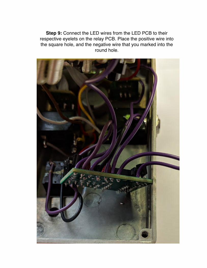
Step 9: Connect the LED wires from the LED PCB to their
respective eyelets on the relay PCB. Place the positive wire into the square hole, and the negative wire that you marked into the
round hole.
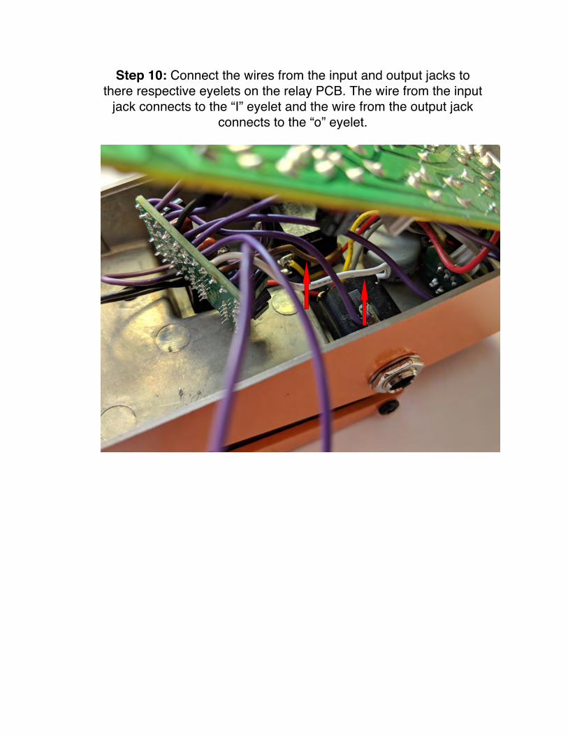
Step 10: Connect the wires from the input and output jacks to there respective eyelets on the relay PCB. The wire from the input
jack connects to the “I” eyelet and the wire from the output jack connects to the “o” eyelet.
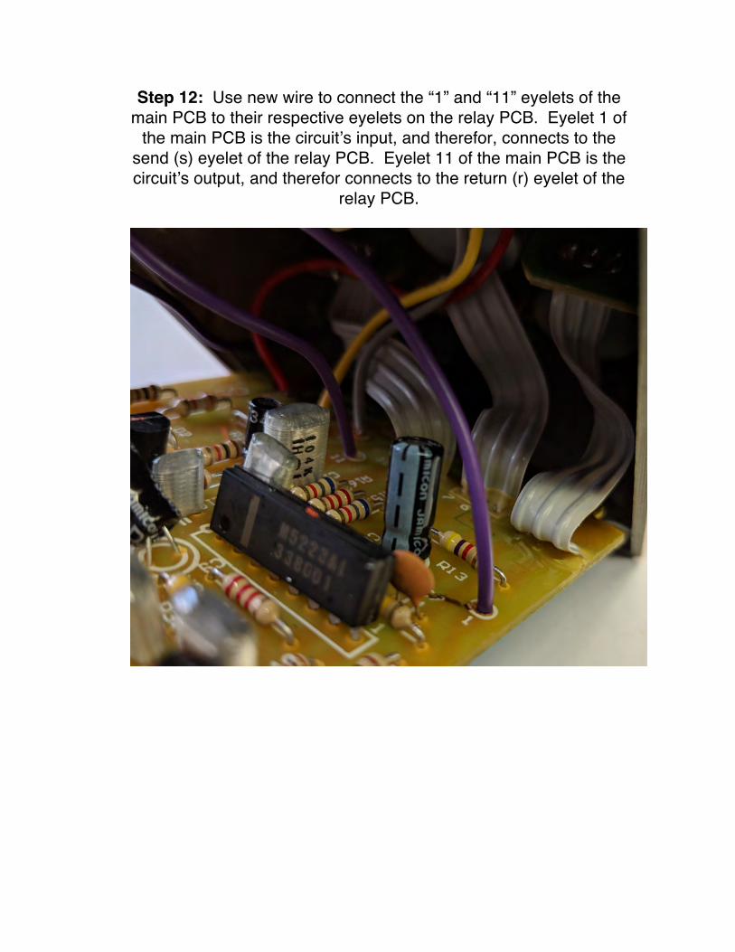
Step 12: Use new wire to connect the “1” and “11” eyelets of the main PCB to their respective eyelets on the relay PCB. Eyelet 1 of
the main PCB is the circuit’s input, and therefor, connects to the send (s) eyelet of the relay PCB. Eyelet 11 of the main PCB is the circuit’s output, and therefor connects to the return (r) eyelet of the
relay PCB.

Step 11: Attach the Relay Bypass board to the pedal using double-sided foam tape. Tip: trim the leads on the solder side of the PCB as closely as possible so that nothing pokes through the tape and shorts out against the pedal’s enclosure. Use two layers
of tape if you need to.

Note:thewiringdiagramsshowaSPDTsoft-touchfootswitch.Youwillbeusingtheexistingtactileswitchthatcamewithyourpedal.Functionally,theyareidentical.