Build IDD System Model in NASTRAN - MDA US Systems … Actuators.pdf · · 2017-02-13Alliance...
8
- 1 - CONCURRENT ACTUATOR DEVELOPMENT FOR THE MARS EXPLORATION ROVER INSTRUMENT DEPLOYMENT DEVICE Richard Fleischner Alliance Spacesystems, Inc. 1250 Lincoln Avenue, Suite 100 Pasadena, California 91103, USA Tel: (+001) 626-296-1373 Fax: (+001) 626-296-0048 Abstract Five unique rotary actuators were developed for the Instrument Deployment Device (IDD), a five degree- of-freedom robotic arm designed to give the Mars Exploration Rover (MER) the ability to gain physical access to the rocks and soil in the Martian environment. These actuators enable the IDD to accurately position each of four separate instruments attached to its end effector against and near geological specimens selected for scientific investigation. This paper describes developmental challenges encountered during the design, fabrication, and testing of the IDD actuators. Shown is that these challenges were associated with fulfilling high torque, high accuracy, low mass, and low volume requirements imposed upon the actuators. In addition, development of the actuators involved integrating their designs into the IDD system. The IDD system is comprised of its actuators, interconnecting structural components, flexible power and signal cables with a corresponding cable management system, launch restraint and re-stow components, and the IDD payload of four scientific instruments. Introduction The MER Mission The MER mission is part of NASA's Mars Exploration Program, a long-term effort of robotic exploration of the Red Planet. The program seeks to take advantage of each launch opportunity to visit Mars, occurring approximately every 26 months as the planets orbit the Sun. Scheduled for two separate launches in June of 2003, the two rovers will be delivered in landing craft to separate sites on Mars in January 2004. Primary among the mission's scientific goals is to search for and characterize a wide range of rocks and soils that hold clues to past water activity on Mars. The spacecraft will be targeted to sites that appear to have been affected by liquid water in the past (description and MER Rover illustration taken from JPL MER website). After the lander has safely come to rest on Mars—in a manner very similar to that of the 1997 Mars Pathfinder mission—the rover will egress from the lander and spend the rest of its 90-Martian-day (approximately 2,220 Earth hours) operational life exploring the surface without further interaction with the lander. The Purpose of the IDD The IDD functions as an approximately 1-meter long, dexterous appendage for the rover, delivering a cluster of four interchangeable scientific instruments to areas and specimens of interest. After deploying from its launch locks, the IDD is free to extend and position itself within its working envelope. In the extended position, however, it is vulnerable to loads (up to 6g’s) generated when the rover’s wheels slip off rocks or steep hills. Before the rover is commanded to drive, the IDD must thus return to a partially constrained position—similar in pose to the launch position—in which it re-cradles itself by engaging certain features at the end effector and elbow joint into a passive re-stowing system. After the rover drives to the intended location, the IDD re-deploys
Transcript of Build IDD System Model in NASTRAN - MDA US Systems … Actuators.pdf · · 2017-02-13Alliance...
- 1 -
CONCURRENT ACTUATOR DEVELOPMENT FOR THE MARS EXPLORATION ROVER INSTRUMENT DEPLOYMENT DEVICE
Richard Fleischner
Alliance Spacesystems, Inc. 1250 Lincoln Avenue, Suite 100
Pasadena, California 91103, USA Tel: (+001) 626-296-1373 Fax: (+001) 626-296-0048
Abstract Five unique rotary actuators were developed for the Instrument Deployment Device (IDD), a five degree-of-freedom robotic arm designed to give the Mars Exploration Rover (MER) the ability to gain physical access to the rocks and soil in the Martian environment. These actuators enable the IDD to accurately position each of four separate instruments attached to its end effector against and near geological specimens selected for scientific investigation. This paper describes developmental challenges encountered during the design, fabrication, and testing of the IDD actuators. Shown is that these challenges were associated with fulfilling high torque, high accuracy, low mass, and low volume requirements imposed upon the actuators. In addition, development of the actuators involved integrating their designs into the IDD system. The IDD system is comprised of its actuators, interconnecting structural components, flexible power and signal cables with a corresponding cable management system, launch restraint and re-stow components, and the IDD payload of four scientific instruments.
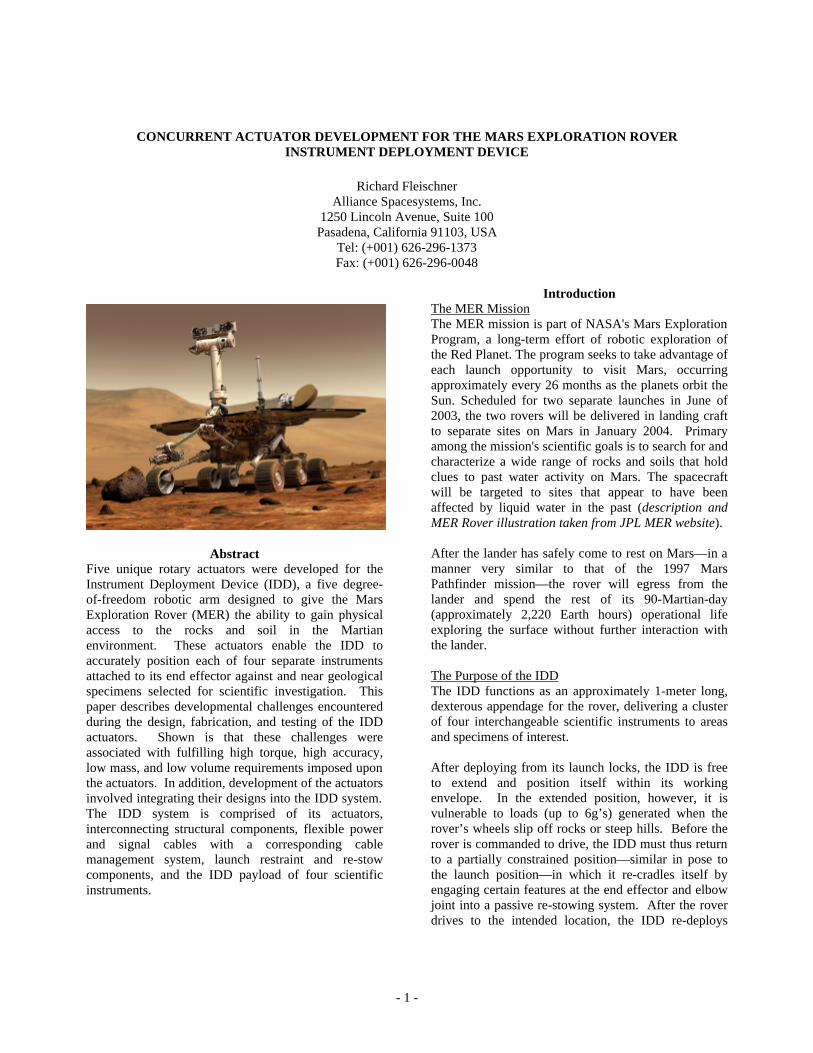
Introduction The MER Mission The MER mission is part of NASA's Mars Exploration Program, a long-term effort of robotic exploration of the Red Planet. The program seeks to take advantage of each launch opportunity to visit Mars, occurring approximately every 26 months as the planets orbit the Sun. Scheduled for two separate launches in June of 2003, the two rovers will be delivered in landing craft to separate sites on Mars in January 2004. Primary among the mission's scientific goals is to search for and characterize a wide range of rocks and soils that hold clues to past water activity on Mars. The spacecraft will be targeted to sites that appear to have been affected by liquid water in the past (description and MER Rover illustration taken from JPL MER website). After the lander has safely come to rest on Mars—in a manner very similar to that of the 1997 Mars Pathfinder mission—the rover will egress from the lander and spend the rest of its 90-Martian-day (approximately 2,220 Earth hours) operational life exploring the surface without further interaction with the lander. The Purpose of the IDD The IDD functions as an approximately 1-meter long, dexterous appendage for the rover, delivering a cluster of four interchangeable scientific instruments to areas and specimens of interest. After deploying from its launch locks, the IDD is free to extend and position itself within its working envelope. In the extended position, however, it is vulnerable to loads (up to 6g’s) generated when the rover’s wheels slip off rocks or steep hills. Before the rover is commanded to drive, the IDD must thus return to a partially constrained position—similar in pose to the launch position—in which it re-cradles itself by engaging certain features at the end effector and elbow joint into a passive re-stowing system. After the rover drives to the intended location, the IDD re-deploys
- 2 -
from the cradled position and delivers the four instruments to the chosen target.
Unit Production and Delivery Over a period of approximately two years, the IDD was conceived and an engineering model unit (EM) and two flight units (F1 and F2) were built and tested. Although the IDD system design underwent many changes throughout the first half of the two-year development period, the IDD concept remained kinematically intact with five degrees of freedom based on scientific needs for positioning its instruments with respect to the target. A set of F3 actuators was built and dynamometer tested but not assembled into an IDD system.
Design Considerations and Drivers The design of the five IDD actuators is subject to several primary requirements based on the MER mission as a whole. The actuators must: • Survive launch loads as well as landing loads of
approximately 42g’s due to the Mars Pathfinder airbag-style landing.
• Survive rover driving/maneuvering loads of
approximately 6g’s. • Operate within a temperature range of –70ºC to
+45ºC. • Survive a non-operational temperature range of
–120ºC to +110ºC. • Be as low mass as possible and allow the IDD to
stow in a very confined launch volume. • Perform throughout the duration of the 90-day MER
mission (a relatively short lifetime for all mechanisms involved).
In addition, there are many requirements and desired characteristics imposed upon the design of the actuators based on IDD operations. Some of the more important are: • The ball bearings used in the actuators are limited to
mean Hertzian contact stresses of 2.76 MPa [400 ksi] for launch and landing, 2.31 MPa [335 ksi] during rover driving/maneuvering, and 1.79 MPa [260 ksi] during IDD operations (positioning and target investigation).
• The actuators, as a group, must have a composite accuracy that enables the IDD to position the “tip” of its instruments to within a maximum allowable ±5 mm sphere of error with ±4 mm repeatability.
• In addition to motor encoder feedback, the actuators
must employ potentiometers with a linearity of at least 0.3% in order to provide absolute position information in the event of an encoder data error or system power loss.
• The actuators must employ known-position hard-
stops for normal encoder calibration and, additionally, recalibration in the event of an encoder count error or system power loss. These hard-stops function secondarily to help protect the IDD from self-collision or collision with the rover.
• The actuators must employ heaters to raise their
temperature to at least –70ºC when the external environment is as cold as –120ºC at a pressure of 8 Torr. The time from heater turn-on until the actuators reach a temperature of at least –70ºC must be 1 hour maximum due to MER system power constraints.
Actuator Design Process
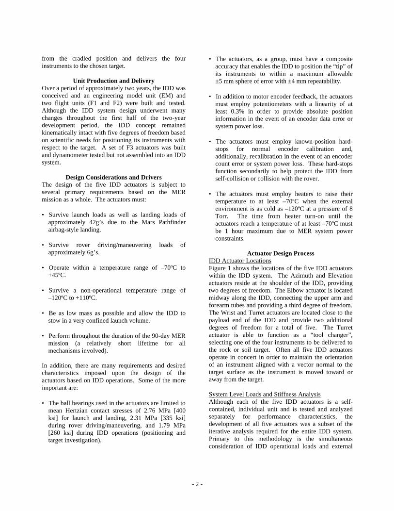
IDD Actuator Locations Figure 1 shows the locations of the five IDD actuators within the IDD system. The Azimuth and Elevation actuators reside at the shoulder of the IDD, providing two degrees of freedom. The Elbow actuator is located midway along the IDD, connecting the upper arm and forearm tubes and providing a third degree of freedom. The Wrist and Turret actuators are located close to the payload end of the IDD and provide two additional degrees of freedom for a total of five. The Turret actuator is able to function as a “tool changer”, selecting one of the four instruments to be delivered to the rock or soil target. Often all five IDD actuators operate in concert in order to maintain the orientation of an instrument aligned with a vector normal to the target surface as the instrument is moved toward or away from the target.
System Level Loads and Stiffness Analysis Although each of the five IDD actuators is a self-contained, individual unit and is tested and analyzed separately for performance characteristics, the development of all five actuators was a subset of the iterative analysis required for the entire IDD system. Primary to this methodology is the simultaneous consideration of IDD operational loads and external
- 3 -
loads arising from launch, landing, and rover driving/maneuvering. The operational loads are iterative in the simple sense that, along with the four-instrument payload, the IDD must lift its own mass; thus, the combined loads of the instruments and the IDD itself produce stresses and torques in the actuators’ structures, gear trains, and ball bearings. In order to suitably handle these loads, the actuators must be designed with adequately sized gears, bearings, housings, etc.—but the larger, and thus heavier, the actuators become, the greater the stresses and torques they exert upon each other.
Elevation Actuator
Azimuth Actuator
Wrist Actuator
Turret Actuator
Elbow Actuator
Figure 1. IDD Actuators
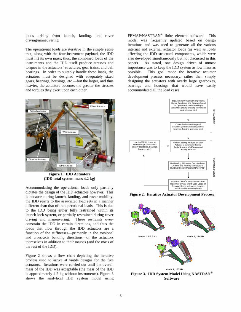
(IDD total system mass 4.2 kg) Accommodating the operational loads only partially dictates the design of the IDD actuators however. This is because during launch, landing, and rover mobility, the IDD reacts to the associated load sets in a manner different than that of the operational loads. This is due to the IDD being either fully restrained within its launch lock system, or partially restrained during rover driving and maneuvering. These restraints over-constrain the IDD in certain directions, and thus the loads that flow through the IDD actuators are a function of the stiffnesses—primarily in the torsional and cross-axis bending directions—of the actuators themselves in addition to their masses (and the mass of the rest of the IDD). Figure 2 shows a flow chart depicting the iterative process used to arrive at viable designs for the five actuators. Iterations were carried out until the overall mass of the IDD was acceptable (the mass of the IDD is approximately 4.2 kg without instruments). Figure 3 shows the analytical IDD system model using
FEMAP/NASTRAN® finite element software. This model was frequently updated based on design iterations and was used to generate all the various internal and external actuator loads (as well as loads affecting the IDD structural components, which were also developed simultaneously but not discussed in this paper). As stated, one design driver of utmost importance was to keep the IDD system as low mass as possible. This goal made the iterative actuator development process necessary, rather than simply designing the actuators with overly large gearboxes, bearings and housings that would have easily accommodated all the load cases.
ITE
RA
TIV
E D
ES
IGN
IN
ITIA
L D
ES
IGN
Size Actuator Structural Components, Output Gearboxes and Bearings Based
on Operational Loads (working in Earth/Mars gravity, pressing instruments
against rocks, etc.)
Create Preliminary Design of Actuators (select candidate gearbox,
bearings, housing geometry, etc.)
Perform Bearing Analysis on Each Actuator to Determine Bearing
Radial & Moment Stiffnesses and Bearing Stresses
Use Bearing Stiffnesses Combined with Gearbox and Housing Stiffnesses to
Build IDD System Model in NASTRAN®
Use NASTRAN® IDD System Model to Determine Overall Worst-Case Loads on
Actuators Based on Launch, Landing, and Rover Maneuvering Loads
Use NASTRAN Loads to Modify Design of Actuators
(modify gearboxes, bearings, housings, etc.)
Figure 2. Iterative Actuator Development Process
Mode 3, 157 Hz
Mode 1, 87.0 Hz Mode 2, 114 Hz
Figure 3. IDD System Model Using NASTRAN®
Software
- 4 -
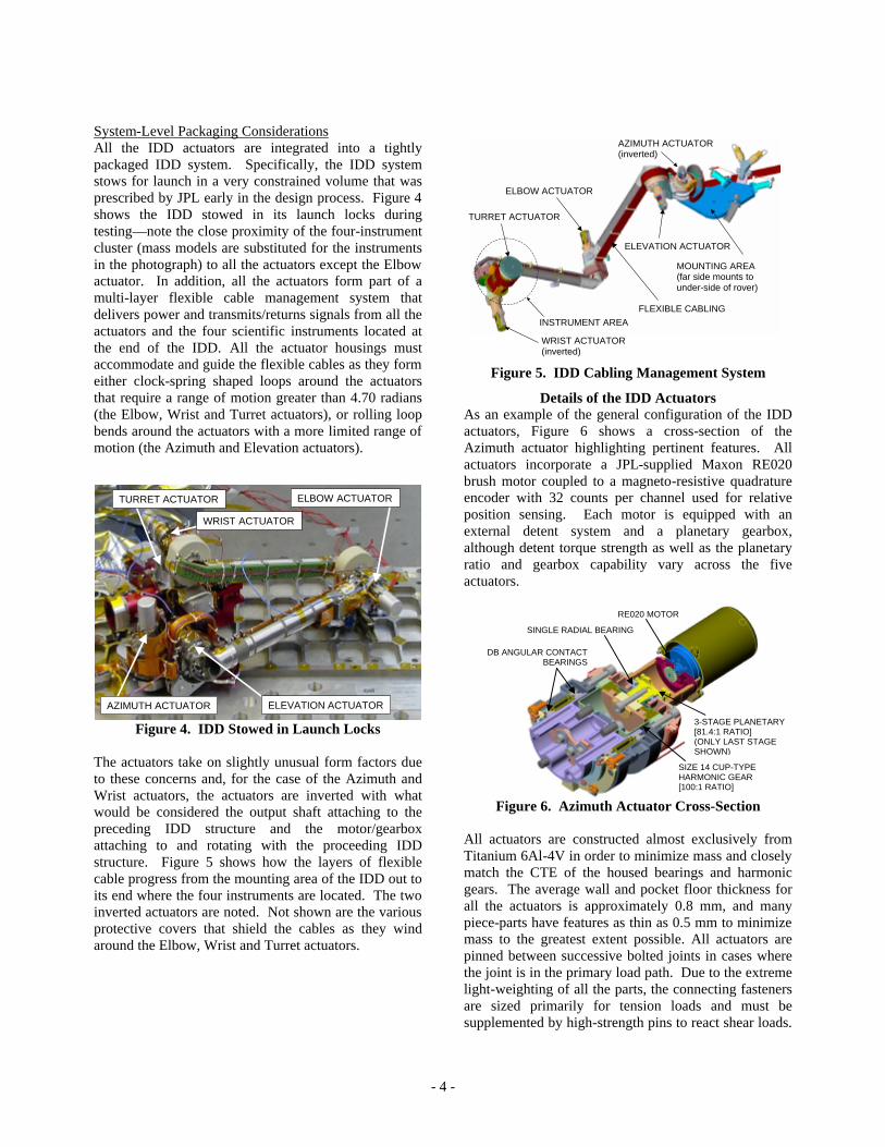
System-Level Packaging Considerations All the IDD actuators are integrated into a tightly packaged IDD system. Specifically, the IDD system stows for launch in a very constrained volume that was prescribed by JPL early in the design process. Figure 4 shows the IDD stowed in its launch locks during testing—note the close proximity of the four-instrument cluster (mass models are substituted for the instruments in the photograph) to all the actuators except the Elbow actuator. In addition, all the actuators form part of a multi-layer flexible cable management system that delivers power and transmits/returns signals from all the actuators and the four scientific instruments located at the end of the IDD. All the actuator housings must accommodate and guide the flexible cables as they form either clock-spring shaped loops around the actuators that require a range of motion greater than 4.70 radians (the Elbow, Wrist and Turret actuators), or rolling loop bends around the actuators with a more limited range of motion (the Azimuth and Elevation actuators).
ELEVATION ACTUATOR AZIMUTH ACTUATOR
TURRET ACTUATOR
WRIST ACTUATOR
ELBOW ACTUATOR
Figure 4. IDD Stowed in Launch Locks
The actuators take on slightly unusual form factors due to these concerns and, for the case of the Azimuth and Wrist actuators, the actuators are inverted with what would be considered the output shaft attaching to the preceding IDD structure and the motor/gearbox attaching to and rotating with the proceeding IDD structure. Figure 5 shows how the layers of flexible cable progress from the mounting area of the IDD out to its end where the four instruments are located. The two inverted actuators are noted. Not shown are the various protective covers that shield the cables as they wind around the Elbow, Wrist and Turret actuators.
FLEXIBLE CABLING
AZIMUTH ACTUATOR (inverted)
ELEVATION ACTUATOR
WRIST ACTUATOR (inverted)
TURRET ACTUATOR
ELBOW ACTUATOR
INSTRUMENT AREA
MOUNTING AREA (far side mounts to under-side of rover)
Figure 5. IDD Cabling Management System
Details of the IDD Actuators As an example of the general configuration of the IDD actuators, Figure 6 shows a cross-section of the Azimuth actuator highlighting pertinent features. All actuators incorporate a JPL-supplied Maxon RE020 brush motor coupled to a magneto-resistive quadrature encoder with 32 counts per channel used for relative position sensing. Each motor is equipped with an external detent system and a planetary gearbox, although detent torque strength as well as the planetary ratio and gearbox capability vary across the five actuators.
SINGLE RADIAL BEARING
RE020 MOTOR
DB ANGULAR CONTACTBEARINGS
SIZE 14 CUP-TYPE HARMONIC GEAR [100:1 RATIO]
3-STAGE PLANETARY [81.4:1 RATIO] (ONLY LAST STAGE SHOWN)
Figure 6. Azimuth Actuator Cross-Section
All actuators are constructed almost exclusively from Titanium 6Al-4V in order to minimize mass and closely match the CTE of the housed bearings and harmonic gears. The average wall and pocket floor thickness for all the actuators is approximately 0.8 mm, and many piece-parts have features as thin as 0.5 mm to minimize mass to the greatest extent possible. All actuators are pinned between successive bolted joints in cases where the joint is in the primary load path. Due to the extreme light-weighting of all the parts, the connecting fasteners are sized primarily for tension loads and must be supplemented by high-strength pins to react shear loads.

- 5 -
Piece-parts that relate the output shaft of the actuator to its hard-stops are also pinned across their interfaces to preclude any relative movement that would affect calibration. The Elbow, Wrist, and Turret actuators all have internal, integral potentiometers custom manufactured by Betatronix, Inc. with the element and wiper components bonded onto Titanium substrate pieces installed into the actuators. For IDD system packaging reasons, the Azimuth and Elevation actuators use externally mounted, gear-driven, self-contained potentiometers, also manufactured by Betatronix, Inc. Each actuator has two thin-film heaters manufactured by Tayco Engineering, Inc. One is bonded to the motor and the other to the output bearing housing. At 28 Volts, the heaters each generate approximately 2-4 Watts of power depending on the actuator. Fairly detailed thermal models of each actuator were created and predicted that at –120ºC and at 8 Torr (Mars) atmospheric pressure each actuator would warm to at least –70ºC, the minimum operating temperature, within one hour of heater turn-on. Properties and performance of the actuators are summarized in Table 1. The values shown are either design values or were measured during testing. Measured values are expressed as the approximate average of four units built of each type actuator. For all actuators, the static torque capability is designed to be larger than the operational output torque capability to correspond with launch, landing, and rover maneuvering loads, which are generally higher than operational loads. In the case of the Azimuth, Elevation, and Elbow actuators, the harmonic gear property that the static ratcheting (“tooth-skipping”) torque threshold is higher than the operational ratcheting torque threshold is exploited. Static ratcheting torque as defined is measured with the harmonic gear output rotationally fixed, and during launch, landing, and rover maneuvering, all actuators are considered essentially fixed. The Wrist and Turret actuators, which only use planetary gears (in order to save mass and packaging volume at the expense of accuracy), are similarly subjected to torques caused by launch and landing loads that exceed maximum required operational torques. The gears, bearings, and bushings that comprise their gearboxes are not designed to continuously operate at the highest loads, but are capable of withstanding them for shorter durations
Table 1. Actuators Summary Azimuth Elevation Elbow Wrist Turret
Gear Reduction Type
3-Stage Planetary/
Size 14 Harmonic
3-Stage Planetary/
Size 14 Harmonic
3-Stage Planetary/
Size 11 Harmonic
5-Stage Planet-
ary
5-Stage Planet-
ary
Gear Ratio 8137:1 8137:1 8137:1 1528:1 1528:1 Total Range of Motion [rad] 2.75 1.25 5.10 5.85 5.95
Static Torque Capability [Nm] 65 65 40 17 28
Operational Output Torque Capability1 [Nm]
45 45 20 9 9
No-load Speed +23ºC, 28V [rad/s] 0.12 0.12 0.12 0.61 0.61
No-load Speed –70ºC, 28V [rad/s] 0.09 0.09 0.09 0.58 0.58
No-load Current +23ºC [A] 0.03 0.03 0.03 0.03 0.03
No-load Current –70ºC [A] 0.16 0.16 0.12 0.05 0.05
Torque/Current Slope +23ºC [Nm/A] 180 180 180 33 33
Torque/Current Slope –70ºC [Nm/A] 140 140 140 33 33
No-load Mechanical Accuracy2 [rad] 0.0015 0.0015 0.0020 0.012 0.012
Min. Stop and Hold Torque [Nm] 28 28 203 5.6 3
Motor Detent Torque Strength [mNm] 64 64 64 64 2
Mass [g] 5905 4805 405 380 350 1Based on highest level tested
2Includes harmonic gear output profile error and hysteresis
3Limited to output torque capability of actuator 4Limited to maximum allowable torque strength 5Includes external potentiometer assembly (approximately 40g)
associated with launch and landing events. Since most actuators were subjected to lower torque levels during dynamometer testing, the highest levels were necessarily achieved during vibration testing of the IDD system, which included a 42g sine burst test (performed on the EM unit only due to undesirable over-amplification effects) to simulate landing.
Testing Dynamometer Testing All actuators were subjected to ambient pressure dynamometer testing throughout the operational temperature range of –70ºC to +45ºC following 1-hour temperature soaks at non-operational temperature limits of –120ºC and +110ºC. The following tests were performed: • No-load current at no-load speed
• No-load current versus speed profiling
• Torque versus speed profiling
• Worst-case startup
• Static back-driving threshold
• Stop and hold threshold
• No-load accuracy
- 6 -
In addition to verifying that the motors and actuators operate with proper margins with respect to torque output, current draw, position holding, overheating, etc., the various tests return data that is extremely important for use in calibrating the encoder of each actuator via initialization against its hard stops. This data consists primarily of the relationship between actuator current draw and corresponding torque output as a function of actuator temperature. The encoder calibration procedure, which is performed by the Flight Operations Team at JPL, relies on each actuator running into either of its hard stops at a known, fixed torque regardless of temperature. Because torque is fixed, the windup of each actuator upon impact with its hard stops is consistent and can therefore be treated as a constant error that is subtracted from the actuator’s encoder position. The actual value of this error is measured during calibration testing at JPL, which is key to characterizing the initialization behavior of the IDD system. If the absolute position of one or more IDD actuators is lost due to a problem with telemetry, joint position can be reestablished by driving one or more actuators to either of its hard stops, which are each at a precisely known angular location. The dynamometer test program was conducted without major data gathering problems, data discrepancies, or damage to the actuators, except for one incident described later. During all tests that required driving the actuator output shafts into their respective hard stops, extreme care was taken to limit the supply current. The current limits were set as a function of testing temperature due to temperature-dependent actuator performance, which was characterized during earlier dynamometer tests in which actuator output torque versus current draw was measured. Prior to being set at “steady-state” (post-startup) values, currents were momentarily (for approximately 1 second) increased for actuator start-up in order to accommodate higher-level transient current draw. Typically, the start-up current limit was incrementally increased from a lower base value until the actuator started, then subsequently lowered to the prescribed steady-state value. All of the twenty total actuators (four sets of five different types) built and tested were run at no-load torque as well as three other torque loading points at temperatures of –70ºC, +23ºC, and +45ºC. As a supplement, the engineering model actuators—the first five actuators built and identical to the flight versions—were tested at additional temperature points of –60ºC, –50ºC, –40ºC, and –20ºC in order to further characterize the torque/current/temperature relationship. The flight
versions were not subjected to this additional testing in order to keep motor revolutions to a minimum. A problem occurred during no-load dynamometer testing when the F1 Elevation actuator failed to start at –70ºC with the start-up current limit set to its 1-Amp maximum. At the time, the 1-Amp start-up current limit, established during EM testing, was thought to be conservatively high based on EM data showing maximum necessary start-up current limits of approximately 0.8 Amp. Following a room-temperature warming cycle of the test chamber and a successful run at room temperature, the actuator performed nominally during a second attempt at –70ºC with the same 1-Amp start-up current limit. In fact, the failure could never be reproduced at any testing temperature. Although it was impossible at the time to recreate the failure, the motor was deemed a credible cause based on feedback evidence that its rotor did not move. This was ascertained by monitoring feedback from the drive electronics, which did not detect any encoder pulses (1 pulse equals 0.2 rad rotor rotation). It was assumed that the problem could be due to an electrical short—telemetry from the drive electronics indicated this as credible but not certain—or a small amount of ice in the motor’s bearings as a result of incomplete dry-Nitrogen purging of the test chamber. The F1 motor was removed and replaced, as were the first two stages of its planetary gearbox, which, as a precaution, were deemed another candidate source of failure, albeit remote. With regard to the gear stages, it was reasoned that lockup of either stage would limit motor rotor motion sufficiently to preclude encoder pulse feedback, even when movement caused by gearbox backlash was taken into account. Ultimately, the rebuilt F1 Elevation actuator completed dynamometer testing and was assembled into the F1 IDD. During subsequent thermal-vacuum chamber testing of the F1 IDD, the F1 Azimuth actuator exhibited behavior similar to that of the F1 Elevation actuator prior to replacement of its motor. Again, the actuator failed to move as the start-up current limit was incrementally increased beyond maximum EM testing levels toward a 1-Amp limit; but unlike the F1 Elevation actuator, small motor rotor movements were indicated by the drive electronics as the limit was approached. Eventually the Azimuth actuator started up before the 1-Amp limit was reached, and its current draw quickly dropped down to a level consistent with earlier dynamometer testing. It was then hypothesized that the original “failure” of the F1 Elevation actuator was actually due to the start-up current limit being set too low. The likelihood of this scenario was strengthened when other F1, F2, and F3

- 7 -
actuators required start-up current limits as high as 1.3 Amps (the previous 1-Amp limit was incrementally increased once the problem was understood). Although special tests were never performed to study the relationship between motor lubricant (Bray 601) viscosity and lubricant temperature specifically near the –70ºC temperature limit, it was qualitatively observed that start-up current draw tended to rise as the testing temperature decreased from –67ºC to –73ºC, the allowable variational range of the nominal –70ºC test point. In other words, at very cold temperatures a few degrees difference in lubricant temperature caused large changes in actuator current draw at start-up. Future testing would help to quantify this sensitive relationship. IDD System-Level Testing Other tests were performed on the IDD system in order to further characterize the five IDD actuators: Geometric characterization testing was performed in order to determine the precise angular position (within 2-4 milliradians) of each actuator’s hard stops with respect to the local coordinate system of each IDD joint. This information is used for hard stop initialization, as discussed, and for confirming that each joint encompasses the specified minimum range of motion. This testing involves temporarily attaching several optical targets to the IDD and using a Leica laser tracking system to measure the locations of the targets as the IDD is driven, joint by joint, though its range of motion. Custom-written software inputs the point cloud information generated as the laser tracker takes multiple snapshots of the moving targets. The software then generates a complete kinematic model of the IDD represented as a “stick-figure” with centers of rotation, link lengths, and link offsets. Repeatability testing was performed in order to measure IDD repeatability error at its end effector, which is required to be less than 4mm. This test involves driving the IDD away from and then back to a known starting position using all five actuators. The location of an optical target mounted on the IDD’s end effector before and after the movement sequence is compared and a three-dimensional error vector is generated. This test, while only a relative—as opposed to an absolute—accuracy test, is influenced by harmonic gear hysteresis and planetary gear backlash effects that were not examined during no-load accuracy dynamometer testing. Actuator ball bearings and structural components were not subjected to cross-moment (perpendicular to the axis of rotation) loading during dynamometer testing;
rather, the IDD system was statically loaded with weights while positioned in various cantilevered orientations in order to cross-load several actuators simultaneously. Certain maximum cross-moment loads produced on bearings and structural components during this test were achieved once more during vibration testing. Although the actuators are stationary during static and vibration testing, they are subjected to 1g operational loading during various functional system tests in the clean room environment and the large thermal-vacuum chamber. These tests are performed throughout the operational temperature range and each joint of the IDD is driven through its range of motion. Heater effectivity testing was performed in order to determine whether or not each actuator’s pair of heaters is capable of raising the actuator’s average temperature from –120ºC to –70ºC within an hour. For this test, the thermal-vacuum chamber is set to a temperature of –120ºC and a Mars pressure of 8 Torr is simulated using a dry nitrogen atmosphere. After the IDD is subjected to a minimum one-hour soak at –120ºC, all its actuator heaters are turned on using a 28V supply and actuator temperatures are monitored via thermocouples. All the IDD actuators heated up to an average temperature of at least –70ºC within an hour, and some motors encased within protective rock shields, such as those on the Azimuth, Elbow and Wrist actuators, reached temperatures as high as –30ºC in that same time period. Figure 7 shows the IDD installed into the thermal-vacuum chamber.
Figure 7. IDD in Thermal-Vacuum Chamber
- 8 -
Conclusions and Lessons Learned As expected, low mass requirements and tight packaging considerations often lead to a difficult implementation of a particular design concept. Beyond the challenges of creating parts and assemblies that are strong, lightweight, accurate, etc., there will most likely be limitations placed on operations, testing, or general performance. This is the case for all the IDD actuators (and the IDD in general). In the event of hard stop calibration or IDD collision, each actuator’s motor is capable of damaging its gearbox without current and speed limiting. The current limiting algorithm is necessarily a function of temperature in order to counteract the higher overall actuator torque constant (Kt) at warmer temperatures where gearbox efficiency is higher (a common scenario). In addition, another layer of current limiting is implemented that is a function of the physical pose of the IDD. That is, based on the real-time orientation of the IDD, each actuator’s current is limited (when necessary) to avoid damaging the other actuators or the IDD structure. A potentially damaging scenario occurs, for example, when a portion of the IDD end effector inadvertently catches on a rock and the Wrist actuator is operated, thus causing large bending loads throughout the IDD. The dependency on software and telemetry sensors that the complex current limiting scheme described requires becomes unavoidable unless the system level decision is made that all mechanisms are to be designed to withstand all or most worst-case scenarios (highest currents and voltages, fastest speeds, etc), even at the expense of considerably higher mass—in this case of the IDD, perhaps twice or more mass than that of the 4.2 kg design presented in this paper. The process of calibrating an actuator’s encoder via initialization at hard stops is also challenging because, as previously discussed, the torque with which the actuator drives into its hard stops, which is a function of motor current and actuator temperature, must be known and consistent so that actuator windup remains consistent. Otherwise, resulting calibration errors will hamper certain critical operations such as re-stowing for rover driving/maneuvering. The IDD is designed so that its actuators are small and light, and hence employ large gear ratios that convert a small supply current error into a large output torque error. The output torque error in turn causes significant windup error due to relatively low gearbox/output shaft torsional stiffness in combination with the low stiffness of the hard stop structures themselves. An improvement would be to employ non-contacting, encoder style (optical) calibration markers that the actuator would sweep past, initializing the drive electronics at a known angle measured precisely during laser tracker testing.
Mechanical hard stops would be included outside the range of the markers in order to prevent over-rotation of the actuator. The challenge associated with this method is to create optical initialization points or micro-switches that would cause triggering with sufficient accuracy. Based on IDD operational requirements, this would call for triggering repeatability within about 2 milliradians. In the case of an optical system, the components would need to be life-qualified throughout the temperature extremes discussed. In addition, the components would have to function and survive in the radiation environments encountered during cruise to Mars and on the Martian surface. As part of the original IDD testing program, life testing one of the IDD units was part of the overall test plan, but time constraints forced life testing to be omitted. This was deemed acceptable because the mission duration is only 90 Martian days and the lifetime number of output revolutions for any actuator, including testing and ground operations, will be no more than 500 at the close of the mission. Much of the design philosophy behind the IDD and its actuators takes this into account: harmonic gears are often operated at torques approaching their momentary peak torque rating; ball bearing stresses during operations are reasonably high (up to 1.79 MPa, or 260 ksi), possibly subjecting the Bray lubricants to pressure cycle degradation. Further testing would be necessary to determine at what point the actuators suffer either breakdown or unacceptable performance loss based on continuous operation under worst-case loading.