Elastic Lateral-Torsional Buckling Load on Circular Fixed ...

Buckling-induced encapsulation of structuredelastic shells under pressureJongmin Shima,1, Claude Perdigoub, Elizabeth R. Chenc, Katia Bertoldia,1,2, and Pedro M. Reisb,1,2
aSchool of Engineering and Applied Sciences, Harvard University, Cambridge, MA 021383; bDepartments of Mechanical Engineering and Civil andEnvironmental Engineering, Massachusetts Institute of Technology, Cambridge, MA 02139; and cDepartment of Mathematics, University of Michigan,Ann Arbor, MI 48109
Edited by* John W. Hutchinson, Harvard University, Cambridge, MA, and approved January 9, 2012 (received for review September 22, 2011)
We introduce a class of continuum shell structures, the Buckliball,which undergoes a structural transformation induced by bucklingunder pressure loading. The geometry of the Buckliball comprises aspherical shell patterned with a regular array of circular voids. Inorder for the pattern transformation to be induced by buckling, thepossible number and arrangement of these voids are found to berestricted to five specific configurations. Below a critical internalpressure, the narrow ligaments between the voids buckle, leadingto a cooperative buckling cascade of the skeleton of the ball. Thisligament buckling leads to closure of the voids and a reduction ofthe total volume of the shell by up to 54%, while remaining sphe-rical, thereby opening the possibility of encapsulation. We use acombination of precision desktop-scale experiments, finite elementsimulations, and scaling analyses to explore the underlying me-chanics of these foldable structures, finding excellent qualitativeand quantitative agreement. Given that this folding mechanismis induced by a mechanical instability, our Buckliball opens the pos-sibility for reversible encapsulation, over a wide range of lengthscales.
Jitterbug ∣ deployable structure
Advances in fabrication technology are enabling functionalorigami-like structures at the nano- and microscales (1–3),
including encapsulation using hollow shell structures (4–7). Inengineering, these structures are receiving increasing attentionfor their promising role as vehicles for drug delivery (8), materialsynthesis agents (9), optical devices (10), and sensors (11). Aninteresting avenue is the introduction of gating (also known asactuation) mechanisms into such capsules by incorporatingfunctional elements into their structural layout toward tunableencapsulation. Coupling conventional actuation mechanisms atthe microscale (including electromagnetic, piezoelectric, thermal,electrochemical, rheological) with buckling may lead to unique ormore efficient functional modes of deformation (12, 13). As anexample, the Venus flytrap combines a swelling mechanism withbuckling behavior to increase the speed of leaf motility (14, 15).Also, an active microhydrogel device was recently designed fordynamic actuation using a swelling-induced elastic instability (16).
There are a few existing hollow shell structures which havegating mechanisms, albeit not driven by buckling. Viruses are anubiquitous class of such examples in nature. Their capsids possessa spherical shell structure that encloses and transports viralnucleic acids (17, 18) and can undergo reversible structural trans-formations by which gated holes can open or close under pHchanges (18). This transformation occurs due to the expansion ofthe vertices of the truncated icosahedral structure of the virus,resulting in 60 hole openings. Using this deployable capability,viruses have been used as protein cages for encapsulation (19).In order to describe the virus swelling/shrinking behavior, Kovácset al. investigated the possible geometric compatibility with poly-hedral models (20, 21).
The Jitterbug, introduced by R. Buckminster Fuller in the1960s, is another example of a hollow shell structure satisfyinggeometric compatibility for gating holes. It enables the morphing
between an octahedron and a cuboctahedron (22), thereby im-parting flexibility to otherwise rigid grid structures. Since then, anumber of studies have generalized the understanding of Jitter-bug-like motion (face rotations at the vertices) through polyhedraltransformations (23–25). These provide a robust set of rules forthe design of spherical deployable structures that can fully closeinto their collapsed state. A popular commercial toy, Hoberman’sTwist-o (Hoberman Associates) (26) which comprises a rigid net-work of struts connected by rotating hinges (Fig. 1A), also morphsfrom an open grid shell into a collapsed configuration. One draw-back of these configurations toward practical applications is thatthe deformation is localized at the vertices of the polyhedra and alarge number of hinges and rotating elements is required toachieve the intended motion.
Here, motivated by these opportunities for augmented motionand deformation of structures, we explore buckling as a possiblegating mechanism for structured spherical shells. Our shells arepatterned with a regular array of circular voids and loaded byreducing the internal pressure. Below a critical pressure, the nar-row ligaments between the voids buckle, leading to a cooperativebuckling cascade of the skeleton of the ball. We exploit this pat-tern transformation that leads to closure of all the holes, which isanalogous to a structural negative Poisson’s ratio effect previouslystudied in two dimensions (27), but now on a three-dimensionalstructure. Because our patterned shell has a geometry reminis-cent of a buckyball (28) and, moreover, it can be activated bybuckling, we name it the Buckliball. We first show the results ofa combination of desktop-scaled experiments (Fig. 1B) and finiteelement (FE) simulations (Fig. 1C) on encapsulation throughpressure-induced buckling of spherical shells. For the sake of ex-perimental convenience and accurate control, we choose pressureas the actuation mechanism for the Buckliball. Consequently,thin membranes covering the holes are introduced in our samplesto enable us to readily load the structure. Because the numericalresults reveal that the characteristic deformation modes are onlymarginally affected by the presence of the membranes, for the sakeof generality we then focus on the skeleton of the Buckliball with-out membranes over the voids and identify the underlying mechan-ical ingredients. Finally, through a scaling analysis, we provide amaster curve for design guidelines of this class of structures.
Experimental ResultsInspired by the construction andmotion of the rigid toy in Fig. 1A,we have made use of rapid prototyping techniques to fabricatea continuum version of the spherical grid shell made of a soft
Author contributions: J.S., K.B., and P.M.R. designed research; J.S., C.P., E.R.C., K.B., andP.M.R. performed research; J.S. analyzed data; and J.S., K.B., and P.M.R. wrote the paper.
The authors declare no conflict of interest.
*This Direct Submission article had a prearranged editor.1J.S., K.B., and P.M.R contributed equally to this work.2To whom correspondence may be addressed. E-mail: [email protected] [email protected].
This article contains supporting information online at www.pnas.org/lookup/suppl/doi:10.1073/pnas.1115674109/-/DCSupplemental.
www.pnas.org/cgi/doi/10.1073/pnas.1115674109 PNAS Early Edition ∣ 1 of 6
ENGINEE
RING

silicone-based rubber (Vinylpolysiloxane with Young’s modulus,E ¼ 784 kPa). The geometry of the spherical elastomeric struc-ture (inner radius Ri ¼ 22.5 mm) comprises a shell (wall thick-ness t ¼ 5 mm) that is patterned with a regular array of 24circular voids that are slightly tapered (17 and 14 mm maximumand minimum diameter, respectively). The voids are distributedin groups of three on each one-eighth of the sphere. A thin mem-brane (thickness h ¼ 0.4� 0.1 mm) covering all the holes isintroduced, to make the structure airtight, which provides thecontinuum shell with a means of pressure-induced actuation. Thisthin membrane allows for an isotropic loading through a distrib-uted pressure difference between the inside and outside of thestructure. More details of the manufacturing and experimentalprocedures are given in Materials and Methods.
The experiments are performed under conditions of imposedvolume using a motorized syringe pump (see Materials andMethods). When the internal pressure is larger than the externalpressure, the structure inflates like a balloon. Conversely, uponreduction of the internal pressure (see Materials and Methods),the behavior is qualitatively different. First, the thin membranessnap-buckle and invert their curvature inward. Subsequently,beyond a critical pressure, the narrow ligaments between theholes buckle on the spherical surface, leading to a cooperativebuckling cascade of the skeleton of the ball. During this process,the initially circular holes evolve into an elliptical shape and even-tually become fully closed. The sequence of progressive deformedshapes is shown in Fig. 1B. It is interesting to note that thisfinal pattern closely resembles the recent work of Li et al. (29)reporting a surface wrinkling pattern of a core-shell soft sphereby volumetric shrinkage, although the structural details of the twosystems are fundamentally different.
In order to monitor the rotation of the narrow ligaments, fourblack dots are marked at the center of each strut (on the top ofthe shell’s surface) and then tracked with digital imaging. InFig. 2A, we plot the averaged trajectory of these four dots (solidblack line) which show that each ligament rotates clockwise byapproximately 75° until the holes are nearly closed. In addition,we image the shell’s projection from above, as its internal pres-sure is reduced, and monitor its outer radius. Fig. 2B (solid blackline) presents the dependence of the measured pressure p and thenominal outer radial strain u∕Ro, where Ro is the initial outerradius and u is the outer radial displacement. Two distinct re-gimes are identified: (i) a linear regime with positive structuralstiffness for small deformations and (ii) a postbuckling regimewith negative structural stiffness.
Because the structure is made of an elastomeric material,the process is fully reversible/repeatable, and upon a decreasein pressure difference, the structure recovers to its original con-figuration, albeit with hysteresis. Note that all the deformationoccurs on a spherical surface with progressively decreasing di-mensions, thereby preserving the original spherical geometry.
An abrupt out-of-sphere buckling (snap buckling), which is highlysensitive to imperfections (30, 31), can occur instead of our in-tended on-sphere buckling, if the geometry and dimension of thespherical shells are not accurately designed.
Finite Element AnalysisWe proceed by performing FE simulations to explore the encap-sulation behavior of the proposed shell structure. Because the ex-periments are performed at imposed volume, volume-controlledconditions are used in the simulations. More details of the FEsimulations are given in Materials and Methods and the SI Text.We present a sequence of the progressive collapse of a Buckliballobtained using FE simulations (Fig. 1C), which is in remarkablequalitative agreement with experiments (Fig. 1B) for the samegeometric and material parameters. Moreover, there is excellentquantitative agreement between experiments and simulations, onthe rotation of the shell ligaments (Fig. 2A).
In order to consider the variation of the measured membranethickness of the experimental specimen (set by the resolution ofthe manufacturing process), simulations were performed withthree different membrane thicknesses (i.e., h ¼ 0.3, 0.4, 0.5 mm).Simulations for these three values of the membrane thicknessdo not show a pronounced difference on the deformed shapes,but they do, however, slightly affect the critical buckling pressuredue to the additional structural stiffness associated with thicker
Fig. 1. Sequence of progressively deformed shapes. (A) Hoberman’s Twist-o,a commercial toy, compressed by hand. (B) Buckliball, made of silicone-based rubber, pressurized by a motorized syringe pump. (C) Finite elementsimulations for the Buckliball. (Scale bars: 3 cm.)
0 2 4 6 8 10 120
2
4
6
8
10
12
x coordinate [mm]
yco
ordi
nate
[mm
]
FEM: h=0.3 mmFEM: h=0.4 mmFEM: h=0.5 mmTest
A
0 0.04 0.08 0.12 0.160
2
4
6
8
Nominal Outer Radial Strain [-]P
ress
ure
[kP
a]
B
FEM: h=0.3 mmFEM: h=0.4 mmFEM: h=0.5 mmTest
Fig. 2. Experimental and numerical results for the Buckliball. Note thateach set of data reported in the figure is obtained from a single test, andall the numerical results are obtained using finite element modeling(FEM). (A) Average rotation of the ligament traced by four black dots whichare marked on the top of the shell’s surface (Inset). The error bars representthe standard deviation for these four ligaments rotations. (B) Relation be-tween the differential pressure of the ball and the nominal outer radial strain(defined by the measured outer radial displacement divided by the initialouter radius). The horizontal error bar for the radial strain is obtained fromimage processing analysis, and the vertical error bar for the pressure is ob-tained from pressure measurement reading duringmultistep volume control.
2 of 6 ∣ www.pnas.org/cgi/doi/10.1073/pnas.1115674109 Shim et al.

membranes. Still, for the dependence of the applied pressureon the outer radial strain presented in Fig. 2B, all three setsof simulation results are in good agreement with the experimentalresults in the linear regime. Excellent agreement between experi-ments and simulation is found for h ¼ 0.5 mm, even though theeffect of the membrane thickness becomes more pronounced atthe onset of buckling. Note that this small discrepancy is attributedto limitations in the accuracy of the membrane thickness due to thefabrication process (see Materials and Methods).
Given theexcellentqualitative andquantitative agreement foundbetween experiments and simulations, we now proceed by focusingprimarily on the FE simulation results to further explore the para-meter space of the system and probe the underlying mechanicalingredients of this buckling-induced pattern transformation.
Mechanical IngredientsThus far, we have demonstrated proof-of-concept of the Buckli-ball through a combination of experiments and FE simulations,for the on-sphere buckling induced by pressure. Moreover, theabove numerical results suggest that the characteristic deforma-tion modes are only marginally affected by the presence of themembrane, given that the membrane thickness is considerablysmaller than any other length scale in the system.
Therefore, for the sake of generality and to seek understandingof the essential features of the proposed encapsulationmechanism,we proceed by focusing on the Buckliball without membranes cov-ering the holes. The original total force previously acting on theBuckliball with membranes covering the holes is now redistributedon the inner surface of the skeleton alone (i.e., Buckliball withoutmembranes covering the holes).
We now investigate the two principal mechanical ingredients:geometric compatibility and gating mechanism. In particular, wefirst concentrate on the arrangement of holes to uncover otherpossible configurations that also lead to the desired encapsula-tion behavior, in addition to the one mentioned above (Fig. 1),and then focus on predicting the buckling loads and modes. Tohelp us refer to the specific deformation modes of the sphericalshells, we use the terms “expanded” and “folded status” to de-scribe the configurations of the ball with open (undeformed) andclosed holes (past the instability), respectively.
Arrangement of the Holes. The set of rules for geometric com-patibility of Jitterbug-like polyhedra has been investigated pre-viously (23, 24), and Verheyen has reported the complete list ofJitterbug-like transformations (25). In light of these studies, wealso explore the hole arrangement on our spherical shells throughpolyhedra. Here, we consider continuum spherical shells where allthe center-to-center distance of adjacent holes are identical so thatall ligaments undergo the first buckling mode in an approximatelyuniform manner, restricting the number of the possible candidatesfrom the complete list of Verheyen.
In order for all the ligaments between neighboring circularholes to undergo a uniform first buckling mode, the folded statusshould meet the following requirements: (a) The same shapedholes should be equally distributed on the spherical shells, and(b) all the circular holes should close uniformly and completely.Mathematically, these mechanical constraints can be rephrasedas follows: The skeleton of the Buckliball should (a′) be a convexuniform polyhedra, excluding the dihedral symmetry group (i.e.,Platonic/Archimedean solids, ref. 32), which are vertex transitiveand have regular faces, and (b′) have a quadrilateral vertex figure.There are only five polyhedra which meet the above require-ments: octahedron, cuboctahedron, rhombicuboctahedron, icosi-dodecahedron, and rhombicosidodecahedron, which can produce(upon face rotations at the vertices) the square-type holes of 6,12, 24, 30, and 60, respectively. These, and only these, ensure thatall the ligaments in the expanded status undergo the first bucklingmode uniformly.
In Fig. 3, we present schematic diagrams of the five possiblepolyhedra on the expanded (Fig. 3A) and folded (Fig. 3C) status.In the figure, the blue-shaded faces of the polyhedra representthe solid parts of the corresponding physical structure and thewhite faces of the expanded status represent the holes that under-go the transformation. As an example, an octahedron in thefolded status can be expanded into a cuboctahedron through facerotations at the vertices, thereby producing six holes, which cor-responds to the number of vertices of the octahedron. Note thatthe cuboctahedron in the expanded status is the famous Jitterbugintroduced by Fuller (22) mentioned above.
In connection with the polyhedra models of expanded status,three-dimensional representations of the initially expanded sphe-rical shells (Fig. 3B) can be obtained by introducing circular voidssuch that two neighboring holes create a narrow ligament at thevertex location of the corresponding polyhedron. Fig. 3D alsoshows the on-sphere buckled shapes for all five possible arrange-ments of the folded status of spherical shells, which are obtainedthrough buckling analysis using FE simulations.
Buckling of the Ligaments. Having identified the geometrical con-straints of the Buckliball configurations, we now explore the de-sign parameters that lead to the desired gating mechanism foractivation under pressure, through simultaneous buckling of allligaments on a spherical surface. For a given hole configuration,
Fig. 3. Geometric compatibility for the arrangement of circular holes on theBuckliballs, restricted to five specific configurations (shown in each row).(A) Expanded Buckliball-related polyhedra: The blue-shaded area correspondsto solid regions and the white area corresponds to holes. (B) Expandedundeformed Buckliballs. (C) Folded Buckliball-related polyhedra. (D) FoldedBuckliballs, which are buckled under inward pressure. Two of the solids inA (i.e., expanded status of the folded rhombicuboctahedron and rhombicosi-dodecahedron) have nonflat faces for the holes. Those two structures aretransformed into polyhedra in their folded status by closing the nonflat holes.
Shim et al. PNAS Early Edition ∣ 3 of 6
ENGINEE
RING

the proposed spherical shells have two dimensionless design para-meters: the ratio of the shell thickness to the inner radius,
τ ¼ tRi
; [1]
and the ratio of the void volume to the intact shell volume,
ψ ¼ N2
�1 − cos
�ϕ − α2
��; [2]
where N is the number of holes for the corresponding polyhe-dron, α is the angle which defines the narrowest width of the liga-ment, and ϕ is the angle between two vectors that originate at theshell center and terminate at two neighboring vertices of a foldedpolyhedron (see Fig. 4 A and B). Because the void’s center inthe expanded polyhedron is placed at the vertex locations ofthe folded polyhedron, ϕ also represents the angle relating thecenter-to-center distance between two adjacent circular voidsin the expanded polyhedron (see SI Text for details). Note thatboth N and ϕ are fixed for a particular hole configuration andthe possible pairs for the five configurations mentioned above
are hN; ϕi ¼ h6; π2i, h12; π
3i,
D24; cos−1
�3þ2
ffiffi2
p5þ2
ffiffi2
p�E
, h30; π5i, andD
60; cos−1�
9þ4ffiffi5
p11þ4
ffiffi5
p�E
. The two additional design parameters
hτ; ψi prescribe the dimensions of the narrow ligaments whichundergo buckling, thereby setting the threshold of the activation.
As observed in the experiments, the narrowest cross-section ofligament in the expanded status of the spherical shells governs thebehavior of the on-sphere buckling of the ball. For this on-spherebuckling to happen, the second moment of area along the radialaxis should be smaller than that along the perpendicular axis—i.e., Irr ≤ Iθθ (see Fig. 4B). The dimension of the narrowest cross-section of ligament is determined by τ and α, so that the restrict-ing condition on the second moment of area reads
ðτ2 þ 3τþ 3Þ2ðτþ 2Þ2ðτ2 þ 2τþ 2Þ ¼
9α sinα16ð1 − cosαÞ ; [3]
where α is given by Eq. 2. Together, Eqs. 2 and 3 provide a rela-tion between the two design parameters hτ; ψi, which is set by theparticular hole arrangement alone—i.e., hN; ϕi. As examples, inFig. 4 C and D, we plot (dotted marked line) the design boundaryset by Eqs. 2 and 3 for the spherical shells with 12 and 24 holes,respectively. Above this line, the Buckliballs are activatedthrough the intended on-sphere buckling mode, whereas belowit, other out-of-sphere (snap) buckling modes occur.
Comparison with FE Simulations. To assess our predictions on theeffect of the hole arrangement and design parameters on liga-ment buckling, we perform a parametric study using FE simula-tions for the buckling analysis. FE models of the initiallyexpanded spherical shells, for the five possible hole arrange-ments, are presented in Fig. 3B, to which an inward pressure isapplied. For all five configurations, we perform a series of FEsimulations on the design parameters hτ; ψi. Representativeresults for shells with 12 and 24 holes are presented in Fig. 4 Cand D as contour maps. In these phase diagrams, regions whereout-of-sphere (snap) buckling occurs are represented in white. Inthe shaded regions where encapsulation (i.e., on-sphere buckling)occurs, the color in the contour plots represents the associatedcritical buckling pressure for onset of on-sphere buckling (nor-malized by the Young’s modulus E), given by the adjacent colorbar. Representative examples of the calculated final on-spherebuckled shapes for all five possible arrangements on the foldedstatus are also presented in Fig. 3D.
For a given hole configuration, this parametric study revealsthat thicker shells and higher void volume fraction are preferableto make the Buckliball buckle on sphere. We highlight that thecontour map boundary between the regions of on-sphere andout-of-sphere buckling is in good agreement with our criterionof design parameters (dashed marked line) based on the second
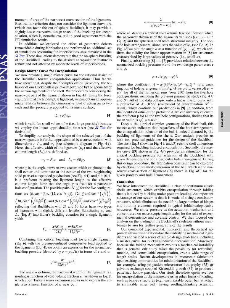
Fig. 4. (A) Representative ligament (Center) extracted from the Buckliball, and a simplified curved column model (Right). (B) Narrowest cross-section of theligament. (C and D) Phase diagram of the two design parameters hτ ¼ t∕Ri; ψi. The color-shaded region indicates on-sphere buckling and the white regionrepresents the out-of-sphere buckling. The magnitude of the critical pressure for the onset of the on-sphere buckling is shown as a contour map with theadjacent color bar; (C) for 12 holes and (D) for 24 holes. The dotted marked lines indicate the analytical criterion from Eq. 3, based on the second moment ofarea. (E) Linear approximation of the normalized effective width of the ligament (α ¼ we∕Ri , see [8]) in terms of effective solid volume fraction ðψc − ψÞ. Thislinear approximation is valid up to the width ratio of α ≈ 0.15. (F) Master curve obtained from the buckling of the simplified ligament shapes. Regardless of thehole arrangements, the normalized critical pressure (ρ ¼ p∕E) for the onset of on-sphere buckling has a distinctive relation with the two design variables hτ; ψi,ρ ≈ Aτðψc − ψÞ2, with the prefactor A ¼ 0.556 and a coefficient of determination of R2 ¼ 0.998.
4 of 6 ∣ www.pnas.org/cgi/doi/10.1073/pnas.1115674109 Shim et al.
moment of area of the narrowest cross-section of the ligaments.Because our criterion does not consider the ligament curvature(which can favor the out-of-sphere buckling), it may provide aslightly less conservative design space of the buckling for encap-sulation, which is, nonetheless, still in good agreement with theFE simulation results.
In addition, we explored the effect of geometric defects(unavoidable during fabrication) and performed an additional setof simulations accounting for imperfections, as summarized in theSI Text. These simulations demonstrate that the on-sphere bucklingof the Buckliball leading to the desired encapsulation feature isrobust and not affected by moderate levels of imperfections.
Design Master Curve for EncapsulationWe now provide a single master curve for the rational design ofthe Buckliball toward encapsulation applications. Thus far wehave shown that, despite their complex overall geometry, the be-havior of our Buckliballs is primarily governed by the geometry ofthe narrow ligaments of the shell. We proceed by considering thenarrowest part of the ligament shown in Fig. 4A. Using the forceequilibrium at each individual ligament, we can obtain an approx-imate relation between the compressive load C acting on its twoends and the pressure p applied to its inner surface,
C ≈R2i αp; [4]
which is valid for small values of α (i.e., large porosity) becausewe employ the linear approximation sinα ≈ α (see SI Text forderivation).
To simplify our analysis, the shape of the selected part of thenarrow ligament is further approximated by a curved column withdimensions t, Le, and we (see schematic diagram in Fig. 4A).Here, the effective width of the ligament (we) and the effectivecolumn length (Le) are defined as
we ¼ Riα and Le ¼ βRiχ; [5]
where χ is the angle between two vectors which originate at theshell center and terminate at the center of the two neighboringsolid parts of a expanded polyhedron (see Fig. 4A), and β ∈ ð0; 1�is a prefactor relating the ligament length to the effectivecolumn length. Note that the angle χ is fixed for a particularhole configuration. The possible pairs hN; χi for the five configura-tions are h6; cos−1ð1
3Þi, h12; cos−1ð 1ffiffi
3p Þi,
D24; π
4and cos−1
� ffiffi23
q �E,D
30; cos−1� ffiffiffiffiffiffiffiffiffiffiffi
5þ2ffiffi5
p15
q �E, and h60; cos−1
� ffiffiffiffiffiffiffiffiffi3þ ffiffi
5p6
q �and cos−1
� ffiffiffiffiffiffiffiffiffi5þ ffiffi
5p10
q �reflecting that Buckliballs with 24 and 60 holes have two typesof ligaments with slightly different lengths. Substituting we andLe (Eq. 5) into Euler’s buckling equation for a single ligamentyields
Ccr ¼π2Etw3
e
12L2e
≈π2EtRiα3
12β2χ 2: [6]
Combining this critical buckling load for a single ligament(Eq. 6) with the pressure-induced compressive load applied tothe ligaments (Eq. 4), we obtain an expression for the normalizedbuckling pressure (denoted by ρ ¼ pcr∕E) in terms of τ and α,
ρ ≈π2
12β2χ 2τα2: [7]
The angle α defining the narrowest width of the ligament is anonlinear function of void volume fraction ψ, as shown in Eq. 2,which upon Taylor’s series expansion allows us to express the an-gle α as a linear function of ψ near ψc :
α ≈2ffiffiffiffiffiffiffiffiffiffiffiffiffiffiffiffiffiffiffiffiffiffiffiffi
ψcðN − ψcÞp ðψc − ψÞ; [8]
where ψc denotes a critical void volume fraction, beyond whichthe narrowest thickness of the ligaments vanishes (i.e., α ¼ 0 inEq. 2) and the spherical shell loses structural integrity. The spe-cific hole arrangement, alone, sets the value of ψc (see Eq. 2). InFig. 4E we plot the angle α as a function of ðψc − ψÞ, which con-firms the validity the linear approximation in [8] for structurescharacterized by large values of porosity (i.e., small α).
Finally, substituting [8] into [7] provides a relation between thenormalized buckling pressure ρ and the two design parameters τand ψ,
ρ ≈Aτðψc − ψÞ2; [9]
where the coefficient A ¼ π2½3β2χ 2ψcðN − ψcÞ�−1 is a weakfunction of hole arrangement. In Fig. 4F we plot ρ versus Aðψc −ψÞ2 for all of the numerical runs (over 250) from the five holeconfigurations, including the previous parametric study (Fig. 4 Cand D). All of the data collapse onto a linear master curve witha prefactor of A ¼ 0.556 (coefficient of determination R2 ¼0.998), which confirms our predictions in [9]. In addition, fromthe identified value of the prefactor A, we can inversely calculatethe prefactor β for all the five hole configurations, finding that itsmean value is hβi ¼ 0.839.
Despite the a priori complex geometry of the Buckliball, thismaster curve indicates that, regardless of the hole arrangement,the encapsulation behavior of the ball is indeed dictated by thebuckling of ligaments of the shells. Our analysis provides uswith two practical guidelines for the design of the Buckliball.The first (Eq. 3 shown in Fig. 4 C andD) sets the shell dimensionsrequired for buckling-induced encapsulation. Secondly, the mas-ter curve ([9] shown in Fig. 4F) provides an estimation for thecritical buckling pressure for actuation of the Buckliball withgiven dimensions and for a particular hole arrangement. Duringthis design procedure, the fabrication constraint can be exploredby checking the smallest dimension of the ball, which is the nar-rowest cross-section of ligament ([8] shown in Fig. 4E) for thegiven porosity and hole arrangement.
ConclusionWe have introduced the Buckliball, a class of continuum elasticshells structures, which exhibits encapsulation through foldingthat is induced by buckling under pressure loading. An importantadvantage of our system is that it is made of a single continuumstructure, which eliminates the need for a large number of hingesand rotating elements required in typical foldable/deployablestructures. We chose pressure as the actuation mechanism andconcentrated on macroscopic length scales for the sake of experi-mental convenience and accurate control. We then focused ouranalysis on the loading of the Buckliball’s skeleton without mem-branes to aim for further generality of the results.
Our combined experimental, numerical, and theoretical ap-proach allowed us to rationalize the underlying mechanical ingre-dients and yielded a series of simple design guidelines, includinga master curve, for buckling-induced encapsulation. Moreover,because the folding mechanism exploits a mechanical instabilitythat is general, our study raises the possibility for reversible,tunable, and controllable encapsulation, over a wide range oflength scales. Recent developments in microscale fabricationopen exciting opportunities for miniaturization of the Buckliball,for example, using projection microstereo lithography (33) orgalvanic exchange-coupled Kirkendall growth (34) to producedpatterned hollow particles. Our study therefore opens avenuesfor encapsulation at the microscale using other forms of loading,such as bilayer structures (e.g., unshrinkable outer ball attachedto shrinkable inner ball) having swelling/shrinking actuation
Shim et al. PNAS Early Edition ∣ 5 of 6
ENGINEE
RING

under various external stimuli including pH, temperature, andwater content, toward practical applications.
Materials and MethodsMaterials. A silicone-based rubber (Elite Double 32; Zhermack) was used tocast the experimental specimen. The material properties were measuredthrough tensile testing, up to the true strain of ϵ ¼ 0.6. No hysteresis wasfound during loading and unloading. The constitute behavior was accuratelycaptured by a Yeoh hyperelastic model (35), whose strain energy isU ¼ ∑3
i¼1 Ci0ðI1 − 3Þ i þ ðJ − 1Þ2i∕Di where C10 ¼ 131, C20 ¼ 0, C30 ¼ 3.5 kPa,and D1 ¼ D2 ¼ D3 ¼ 38.2 GPa−1. Here, I1 ¼ tr½devðFTFÞ�, J ¼ det½F�, and F isthe deformation gradient. Two of the Yeoh model parameters are relatedto the conventional shear modulus (G0) and bulk modulus (K0) at zero strain:C10 ¼ G0∕2, D1 ¼ 2∕K0:
Spherical Shell Specimen. A mold was fabricated using a 3D printer (ElitePrinter; Dimension) to cast one-half of a spherical shell. After demolding,two halves were joined using the same polymer as adhesive agent. Note thatthe continuum shell and the thin membrane are constructed as a single piece.The coordinates of the holes were obtained from the vertices of the corre-sponding polyhedron, and the geometry of each hole was designed such thatthe hole portion is cut out from the spherical shell by a cone whose vertex isat the center of the sphere. A thin membrane located at the inner radiuscovered all the holes, thereby making the shell airtight. In order to extractthe air from the shell, a 2-mm inlet was introduced at the shell’s base andconnected to the syringe through silicone tubing. The ball dimensions wereas follows: inner radius Ri ¼ 22.5 mm, shell thickness t ¼ 5 mm, membranethickness h ¼ 0.4� 0.1 mm, void volume fraction ψ ¼ 0.6. Note that the var-iation of the measured membrane thickness reflects the resolution (0.1 mm)of the 3D printer used to make the molds. In addition, we introduced taperedfillets (between the membranes and the skeleton) to the samples to preventthe membranes from being damaged during the demolding procedure (thefillet radius is 1.0 mm), and we applied extra material both to the hemisphe-rical joints to connect two hemispheres and to the thin membranes to makethem airtight, so increasing the stiffness of the samples.
Pressure Testing and Analysis. The pressure-driven experimental setupwas comprised of a syringe (BD 60CC Irrigation Syringe; Becton Dickinson),
a syringe pump (NE-1000 Single Syringe Pump; New Era Pump Systems,Inc.), a pressure gauge (MPXV4115VC6U-ND; Digi-Key), silicone tubing(51135K84; McMaster-Carr), and a camera (D90; Nikon). During the withdra-wal of the syringe pump (average rate of 0.1 mm3∕s), pictures taken with thecamera and pressure values were digitized (0.1 Hz acquisition rate). The totalduration of an experimental run was approximately 10 min. The rotation ofthe spherical shell was monitored by tracking four black dots on top of theshell. In parallel, the outer radius of the shell was estimated by measuring itsprojected area. Both the rotation of the ligaments and the change of theshell diameter were analyzed by digital image processing using Matlab.
Numerical Simulations. The commercial FE software Abaqus FEA was used forboth buckling and postbuckling analysis. The Abaqus/Standard solver wasemployed for all the simulations—i.e., for both buckling and postbucklinganalysis. For the buckling analyses of the Buckliball without membranes cov-ering the holes, models were built using quadratic solid elements (Abaquselement type C3D10MH with a mesh sweeping seed size of 2.5 mm) andthe analyses were performed under pressure loading. For the postbucklinganalysis, the membrane covering the holes was included in the model and thesimulations were performed under volume-controlled conditions. Both theskeleton and the membranes were modeled using quadratic solid elements(element type C3D10MH with a mesh sweeping seed size of 2.5 mm). Toperform the simulation under volume-control conditions, the Buckliballwas modeled as a spherical shell filled with fluid employing hydrostatic fluidelements (F3D3 with a mesh sweeping seed size of 1.25 mm). The fluid wasassumed to be compressible air having a density of 1.204 kg∕m3 at 20 °C, andits volume was progressively reduced during simulations. More details on theFE simulations are provided in the SI Text.
ACKNOWLEDGMENTS. We are grateful to Zorana Zeravcic for helpful discus-sions, and to Harvard School of Engineering and Applied Sciences AcademicComputing for their support. This work has been partially supported by theHarvard Materials Research Science and Engineering Center under NationalScience Foundation Award DMR-0820484 and by the MIT-France program.K.B. acknowledges startup funds from the School of Engineering and AppliedSciences, Harvard and the support of the Kavli Institute at Harvard University.P.M.R. acknowledges startup funds from the Departments of MechanicalEngineering and Civil and Environmental Engineering, MIT.
1. Ocampo JMZ, et al. (2003) Optical actuation of micromirrors fabricated by the micro-origami technique. Appl Phys Lett 83:3647–3649.
2. Li XL (2008) Strain induced semiconductor nanotubes: From formation process todevice applications. J Phys D Appl Phys 41:193001.
3. van Honschoten JW, et al. (2010) Elastocapillary fabrication of three-dimensionalmicrostructures. Appl Phys Lett 97:014103.
4. Caruso F, Caruso RA, Möhwald H (1998) Nanoengineering of inorganic and hybridhollow spheres by collodial templating. Science 282:1111–1114.
5. Peyratout CS, Dahne L (2004) Tailor-made polyelectrolyte microcapsules: From multi-layers to smart containers. Angew Chem Int Edit Engl 43:3762–3783.
6. Suh WH, Jang AR, Suh YH, Suslick KS (2006) Porous, hollow, and ball-in-ballmetal oxide microspheres: Preparation, endocytosis, and cytotoxicity. Adv Mater18:1832–1837.
7. Shiomi T, et al. (2009) Synthesis of a cagelike hollow aluminosilicate with vermiculatemicro-through-holes and its application to ship-in-bottle encapsulation of protein.Small 5:67–71.
8. Zhu YF, et al. (2005) Stimuli-responsive controlled drug release from a hollow meso-porous silica sphere/polyelectrolyte multilayer core-shell structure. Angew Chem IntEdit Engl 44:5083–5087.
9. Ren N, et al. (2004) Mesoporous microcapsules with noble metal or noble metal oxideshells and their application in electrocatalysis. J Mater Chem 14:3548–3552.
10. Hao E, et al. (2004) Optical Properties of Metal Nanoshells. J Phys Chem B108:1224–1229.
11. Martinez CJ, Hockey B, Montgomery CB, Semancik S (2005) Porous tin oxide nano-structured microspheres for sensor applications. Langmuir 21:7937–7944.
12. Kornbluh R, Peirine R, Pei Q, Oh S, Joseph J (2000) Ultrahigh strain response of field-actuated elastomeric polymers. Proc SPIE 3987:51–64.
13. Oh KW, Ahn CH (2006) A review of microvalves. J Micromech Microeng 16:R13–R39.14. Forterre Y, Skotheim JM, Dumais J, Mahadevan L (2005) How the Venus flytrap snaps.
Nature 433:421–425.15. Skotheim JM, Mahadevan L (2005) Physical limits and design principles for plant and
fungal movements. Science 308:1308–1310.16. Lee H, Xia C, Fang NX (2010) First jump of microgel; actuation speed enhancement by
elastic instability. Soft Matter 6:4342–4345.17. Baker TS, Olson NH, Fuller SD (1999) Adding the third dimension to virus life cycles:
Three-dimensional reconstruction of icosahedral viruses from cryo-electron micro-graphs. Microbiol Mol Biol Rev 63:862–922.
18. Speir JA, Munshi S, Wang G, Baker TS, Johnson JE (1995) Structures of the native andswollen forms of cowpea chlorotic mottle virus determined by X-ray crystallographyand cryo-electron microscopy. Structure 3:63–78.
19. Douglas T, Young M (1998) Host-guest encapsulation of materials by assembled virusprotein cages. Nature 393:152–155.
20. Kovács F, Tarnai T, Fowler PW, Guest SD (2004) A class of expandable polyhedral struc-tures. Int J Solids Struct 41:1119–1137.
21. Kovács F, Tarnai T, Guest SD, Gowler PW (2004) Double-link expandohedra: A mechan-ical model for expansion of a virus. Proc R Soc London A Math Phys 460:3192–3202.
22. Fuller RB (1982) Synergetics: Explorations in the Geometry of Thinking (MacMillan,New York).
23. Stuart RD (1963) Polyhedral and Mosaic Transformations (Student Publications of theSchool of Design, North Carolina State University, Raleigh, NC).
24. Clinton JD (1971) Advanced structural geometry studies. Part 2: A geometric trans-formation concept for expanding rigid structures. (NASA, Washington, DC) ReportCR-1735.
25. Verheyen F (1989) The complete set of Jitterbug transformers and the analysis of theirmotion. Comput Math Appl 17:203–250.
26. Hoberman C (1990) Reversibly expandable doubly-curved truss structure. US Patent4942700.
27. Bertoldi K, Reis PM, Willshaw S, Mullin T (2009) Negative Poisson’s ratio behaviorinduced by an elastic instability. Adv Mater 22:361–366.
28. Kroto HW, Heath JR, O’Brien SC, Curl RF, Smalley RE (1985) C60: Buckminster-fullerene.Nature 318:162–163.
29. Li B, Cao YP, Feng XQ, Gao H (2011) Surface wrikling patterns on a core-shell softsphere. Phys Rev Lett 106:234301.
30. Hutchinson JW (1967) Imperfection sensitivity of externally pressurized sphericalshells. J Appl Mech 34:49–55.
31. Carlson RL, Sendelbeck RL, Hoff NJ (1967) Experimental studies of the buckling of com-plete spherical shells. Exp Mech 7:281–288.
32. Cromwell PR (1997) Polyhedra (Cambridge Univ Press, Cambridge, UK).33. Sun C, Fang N, Wu DM, Zhang X (2005) Projection micro-stereolithography using
digital micro-mirror dynamic mask. Sens Actuators A Phys 121:113–120.34. González E, Arbiol J, Puntes VF (2011) Carving at the nanoscale: Sequential galvanic
exchange and Kirkendall growth at room temperature. Science 334:1377–1380.35. Yeoh OH (1993) Some forms of the strain energy function for rubber. Rubber Chem
Technol 66:754–771.
6 of 6 ∣ www.pnas.org/cgi/doi/10.1073/pnas.1115674109 Shim et al.