Buckling and post-buckling of long pressurized elastic thin-walled ...
21
International Journal of Non-Linear Mechanics 41 (2006) 491 – 511 www.elsevier.com/locate/nlm Buckling and post-buckling of long pressurized elastic thin-walled tubes under in-plane bending S. Houliara, S.A. Karamanos ∗ Department of Mechanical and Industrial Engineering, University of Thessaly, Volos 38334, Greece Received 14 September 2004; received in revised form 15 November 2005; accepted 16 November 2005 Abstract The present paper focuses on the structural stability of long uniformly pressurized thin elastic tubular shells subjected to in-plane bending. Using a special-purpose non-linear finite element technique, bifurcation on the pre-buckling ovalization equilibrium path is detected, and the post-buckling path is traced. Furthermore, the influence of pressure (internal and/or external) as well as the effects of radius-to-thickness ratio, initial curvature and initial ovality on the bifurcation moment, curvature and the corresponding wavelength, are examined. The local character of buckling in the circumferential direction is also demonstrated, especially for thin-walled tubes. This observation motivates the development of a simplified analytical formulation for tube bifurcation, which considers the presence of pressure, initial curvature and ovality, and results in closed-form expressions of very good accuracy, for tubes with relatively small initial curvature. Finally, aspects of tube bifurcation are illustrated using a simple mechanical model, which considers the ovalized pre-buckling state and the effects of pressure. 2006 Elsevier Ltd. All rights reserved. Keywords: Tube; Cylindrical shell; Thin-walled; Ovalization; Stability; Bifurcation; Buckling 1. Introduction The present work investigates the stability of long elastic thin-walled tubes subjected to in-plane bending and pressure (internal or external). Under pure bending loading conditions, the tube cross-section is distorted (ovalizes), resulting in loss of bending stiffness and a limit point instability, referred to as “ovalization” or Brazier instability. The bending moment at the limit point was calculated by Brazier [1] equal to M BR = 0.987Et 2 r/ 1 − 2 , where r and t are the cross-sectional ra- dius and thickness, respectively, E isYoung’s modulus and is Poisson’s ratio. However, the increased axial stress at the com- pression side, accentuated because of ovalization causes bifur- cation instability (buckling) in a form of longitudinal wavy- type “wrinkles”, usually before a limit moment is reached. This constitutes a buckling problem associated with a highly non- linear pre-buckling state, where the compression zone of the cylindrical shell wall has a double curvature in the longitudinal and in the hoop direction. In the recent years, this problem has ∗ Corresponding author. Tel.: +30 24210 74086; fax: +30 24210 74012. E-mail address: [email protected] (S.A. Karamanos). 0020-7462/$ - see front matter 2006 Elsevier Ltd. All rights reserved. doi:10.1016/j.ijnonlinmec.2005.11.002 received significant attention due to its application in nanome- chanics; more specifically, several attempts have been reported to apply shell stability concepts in order to simulate the struc- tural stiffness and explain the buckling and post-buckling re- sponse of carbon nanotubes subjected to bending loads [2–4]. In an early publication, Seide and Weingarten [5] investi- gated bifurcation of initially straight circular tubes under bend- ing, assuming a linear (non-deformed) pre-buckling state, and a Ritz-type bifurcation solution in terms of trigonometric func- tions. Their numerical results indicated that the critical (buck- ling) moment M cr of a cylinder corresponds to a nominal bending stress cr = M cr /(r 2 t), which is quite close to the buckling stress of the cylinder under uniform compression, thus the following equations may offer a good approxima- tion for the buckling moment and the corresponding bending stress: M cr = 1.813 Et 2 r (1 − 2 ) , (1) cr = E 3(1 − 2 ) t r . (2)
Transcript of Buckling and post-buckling of long pressurized elastic thin-walled ...

International Journal of Non-Linear Mechanics 41 (2006) 491–511www.elsevier.com/locate/nlm
Buckling and post-buckling of long pressurized elasticthin-walled tubes under in-plane bending
S. Houliara, S.A. Karamanos∗
Department of Mechanical and Industrial Engineering, University of Thessaly, Volos 38334, Greece
Received 14 September 2004; received in revised form 15 November 2005; accepted 16 November 2005
Abstract
The present paper focuses on the structural stability of long uniformly pressurized thin elastic tubular shells subjected to in-plane bending.Using a special-purpose non-linear finite element technique, bifurcation on the pre-buckling ovalization equilibrium path is detected, and thepost-buckling path is traced. Furthermore, the influence of pressure (internal and/or external) as well as the effects of radius-to-thickness ratio,initial curvature and initial ovality on the bifurcation moment, curvature and the corresponding wavelength, are examined. The local characterof buckling in the circumferential direction is also demonstrated, especially for thin-walled tubes. This observation motivates the developmentof a simplified analytical formulation for tube bifurcation, which considers the presence of pressure, initial curvature and ovality, and resultsin closed-form expressions of very good accuracy, for tubes with relatively small initial curvature. Finally, aspects of tube bifurcation areillustrated using a simple mechanical model, which considers the ovalized pre-buckling state and the effects of pressure.� 2006 Elsevier Ltd. All rights reserved.
Keywords: Tube; Cylindrical shell; Thin-walled; Ovalization; Stability; Bifurcation; Buckling
1. Introduction
The present work investigates the stability of long elasticthin-walled tubes subjected to in-plane bending and pressure(internal or external). Under pure bending loading conditions,the tube cross-section is distorted (ovalizes), resulting in lossof bending stiffness and a limit point instability, referred toas “ovalization” or Brazier instability. The bending moment atthe limit point was calculated by Brazier [1] equal to MBR =0.987Et2r/
√1 − �2, where r and t are the cross-sectional ra-
dius and thickness, respectively, E is Young’s modulus and � isPoisson’s ratio. However, the increased axial stress at the com-pression side, accentuated because of ovalization causes bifur-cation instability (buckling) in a form of longitudinal wavy-type “wrinkles”, usually before a limit moment is reached. Thisconstitutes a buckling problem associated with a highly non-linear pre-buckling state, where the compression zone of thecylindrical shell wall has a double curvature in the longitudinaland in the hoop direction. In the recent years, this problem has
∗ Corresponding author. Tel.: +30 24210 74086; fax: +30 24210 74012.E-mail address: [email protected] (S.A. Karamanos).
0020-7462/$ - see front matter � 2006 Elsevier Ltd. All rights reserved.doi:10.1016/j.ijnonlinmec.2005.11.002
received significant attention due to its application in nanome-chanics; more specifically, several attempts have been reportedto apply shell stability concepts in order to simulate the struc-tural stiffness and explain the buckling and post-buckling re-sponse of carbon nanotubes subjected to bending loads [2–4].
In an early publication, Seide and Weingarten [5] investi-gated bifurcation of initially straight circular tubes under bend-ing, assuming a linear (non-deformed) pre-buckling state, anda Ritz-type bifurcation solution in terms of trigonometric func-tions. Their numerical results indicated that the critical (buck-ling) moment Mcr of a cylinder corresponds to a nominalbending stress �cr = Mcr/(�r2t), which is quite close to thebuckling stress of the cylinder under uniform compression,thus the following equations may offer a good approxima-tion for the buckling moment and the corresponding bendingstress:
Mcr = 1.813Et2r√(1 − �2)
, (1)
�cr = E√3(1 − �2)
(t
r
). (2)

492 S. Houliara, S.A. Karamanos / International Journal of Non-Linear Mechanics 41 (2006) 491–511
Kempner and Chen [6], considering the DMV shell equa-tions and assuming a linear pre-buckling state, examined bi-furcation instability of circular and oval cylinders under bend-ing, in the presence of axial force. Furthermore, they employedKoiter–Budiansky initial post-buckling theory [7,8] to inves-tigate post-buckling behavior, in terms of trigonometric func-tions in the longitudinal direction, and obtained an asymptoticapproximation of the secondary path, which indicated a sym-metric bifurcation point, and an initially unstable secondaryequilibrium path.
The solutions in [5] and [6] neglect cross-sectional ovaliza-tion on the pre-buckling state and, therefore, they predict an un-reasonably high value of buckling moment for long tubes. Thenon-linear effects of the ovalized pre-buckling configuration onthe bending response of tubes were considered by Axelrad [9].In this work, it was assumed that bifurcation occurs when themaximum compressive bending stress value reaches the criticalstress value for a uniformly compressed circular tube of radiusequal to the local radius of the ovalized shell at the “critical”point. By consequence, Eq. (2) may be applicable in a localsense, replacing the initial hoop curvature 1/r with the currentcurvature in the hoop direction at the location where bucklinginitiates. Using the same concept, Emmerling [10] computedthe bifurcation bending moment and curvature of initially ovalcylinders under bending and pressure.
Stephens et al. [11], using a finite-difference discretizationof shell stability equations, investigated bifurcation of finite-length, initially-straight tubes under bending, considering pre-buckling ovalization, as well as end-effects, and calculated bi-furcation moments for different levels of pressure. The bucklingmoment of long tubes was calculated close to Brazier ovaliza-tion limit moment (MBR = 0.987Et2r/
√1 − �2). Fabian [12]
examined buckling of thin elastic initially straight tubes underbending and pressure (internal or external), through a pertur-bation of the non-linear DMV shallow-shell equations. Resultsfrom the linearized (first-order) stability problem indicated thatbifurcation occurs on the primary path before the ovalizationlimit point, regardless the level of pressure. Subsequently, usingKoiter–Budiansky initial post-buckling theory, as described in[13] for non-linear pre-buckling state, and assuming a trigono-metric variation of stress and displacements in the longitudinaldirection, an asymptotic approximation of the post-bucklingpath was obtained.
Ju and Kyriakides [14] reported few numerical results forbending buckling of initially straight non-pressurized elastictubes (r/t =100) using the non-linear Sanders’ shell equationsand discretization in terms of trigonometric functions. The re-sults verified that bifurcation occurs before a limit moment isreached and it is attained on the primary path. In addition, anunstable post-buckling path was observed. In a recent paper[15], using a special-purpose finite element formulation, insta-bilities of non-pressurized elastic tubes with radius-to-thicknessratio equal to 120 were investigated, with emphasis on the ef-fects of relatively small initial curvature. Furthermore, it wasconcluded that, depending on the initial curvature value and thedirection of bending load, buckling may occur before or afterthe limit point of the primary ovalization path. It was also found
that depending on the hoop curvature and longitudinal stressvariation, buckling may occur at various locations around thecross-section.
The present paper extends the investigation presented in [15],and examines the stability of initially-ovalized thin elastic tubessubjected to combined pressure and bending loading. The tubesare infinitely long and may be initially straight or bent with alongitudinal radius of curvature R significantly larger than thecross-sectional radius r (R/r > 80). The dependence of buck-ling moment, curvature, wavelength and post-buckling responseon the level of pressure, as well as on the value of initial cur-vature and initial ovality is examined in detail. Furthermore,the influence of tube thickness on the response is examined,considering the cross-sectional radius-to-thickness ratio (r/t)
to range between 20 and 720. Buckling configurations are cal-culated and discussed, and post-buckling paths are traced withparticular emphasis on the location of buckling patterns aroundtube circumference. Motivated by the small size of the buck-ling zone in the hoop direction, a simplified analytical bifur-cation solution is also developed, which employs a variationalovalization solution, presented in the Appendix, and results inclosed-form expressions for the buckling curvature, the buck-ling moment and the corresponding wavelength. The analyticalexpressions are compared with numerical results. Finally, us-ing a simple mechanical model, proposed elsewhere, enhancedto account for the pre-buckling ovalized state and the effectsof pressure, the bifurcation response of tubes is illustrated in aqualitative manner.
2. Numerical technique
Numerical results are obtained through a non-linear varia-tional formulation of the elastic shell, outlined in this section,based on a special-purpose “tube” finite element. The formula-tion, was introduced in [16] for the analysis of inelastic thick-walled cylinders, and has also been successfully employed in[15] for thin-walled elastic tubes.
2.1. Formulation and finite element discretization
A Lagrangian formulation of the tube is adopted using con-vected coordinates in the hoop, longitudinal and radial direc-tion (denoted as �, �, �, respectively), as described in detail byNeedleman [17]. The tube is considered as an isotropic hypo-elastic continuum. The constitutive equations relate the con-vected rate of Kirchhoff stress to the rate-of-deformation ten-sor. Following classical shell theory [8], the traction componentnormal to any shell lamina is imposed to be zero and tube thick-ness is assumed constant. The present formulation accounts forpressure loading, which is applied on the tube surface as a fol-lower distributed load, always normal to the deformed shapeof the tubular shell wall.
Discretization of the elastic continuum is considered throughthe three-node “tube element”, which combines longitudinal(beam-type) with cross-sectional deformation (Fig. 1). Nodesare located on the tube axis, which lies on the plane of bending,

S. Houliara, S.A. Karamanos / International Journal of Non-Linear Mechanics 41 (2006) 491–511 493
R
r
(1) (2)
(3)
x2
x1 x3
2u
(1)3u
(1)1�
(1)xe
(1)ye
(1)ze
x
y
x
y
x
y
�
��
(2)
(1)2
(1)xe
(1)ye
(1)ze
(k)
w( )
u( )
( )
v( )
reference lineof tube section correspondingto node (k)
( )kxe
( )kye
( )kze
x
y
(k)
�
�
�
�
(�)
�
( )kxe
( )kye
( )kze
Fig. 1. Tube element and deformation parameters (displacements and rotations).
and each node possesses three degrees of freedom (two transla-tional and one rotational). A reference line is chosen within thecross-section at node (k) and a local Cartesian coordinate sys-tem is defined, so that the x, y axes define the cross-sectionalplane. The orientation of node (k) is defined by the positionof three orthonormal vectors e(k)
x , e(k)y and e(k)
z . For in-plane(ovalization) deformation, fibers initially normal to the refer-ence line remain normal to the reference line. Furthermore,those fibers may rotate in the out-of-plane direction by angle�(�). Using quadratic interpolation in the longitudinal direc-tion, the position vector x(�, �, �)of an arbitrary point at thedeformed configuration is
x(�, �, �) =3∑
k=1
[(x(k) + r(k)(�) + �n(k)(�)
+ ��(�)e(k)z )N(k)(�)], (3)
where x(k) is the position vector of node (k), r(k)(�) is theposition of the reference line at a certain cross-section relative tothe corresponding node (k), n(k)(�) is the “in-plane” outwardnormal of the reference line at the deformed configuration andN(k)(�) is the corresponding Lagrangian quadratic polynomial.Using non-linear ring theory [8], vector functions r(k)(�) andn(k)(�), can be expressed in terms of the radial, tangential andout-of-plane displacements of the reference line, denoted asw(�), v(�), u(�), respectively. Functions w(�), v(�), u(�) and�(�) are discretized as follows:
w(�) = a0 + a1 sin � +∑
n=2,4,6,...
an cos n�
+∑
n=3,5,7,...
an sin n�, (4)
v(�) = − a1 cos � +∑
n=2,4,6,...
bn sin n�
+∑
n=3,5,7,...
bn cos n�, (5)
u(�) =∑
n=2,4,6,...
cn cos n� +∑
n=3,5,7,...
cn sin n�, (6)
�(�) =∑
n=0,2,4,6,...
�n cos n� +∑
n=1,3,5,7,...
�n sin n�. (7)
Coefficients an, bn refer to in-plane cross-sectional deforma-tion, and express the ovalization of the cross-section, whereascn, �n refer to out-of-plane (“warping”) cross-sectional defor-mation.
2.2. Numerical implementation
A 16th degree expansion [n�16 in Eqs. (4)–(7)] forw(�), v(�), u(�) and �(�) is found to be adequate for the pur-poses of the present study. Regarding the number of integrationpoints in the circumferential direction, the 16th degree expan-sion requires 23 equally spaced integration points around thehalf-circumference. Three and two Gauss points are used inthe radial (through the thickness) direction and the longitudinaldirection of the “tube” element, respectively.
A periodic solution along the tube is considered for the post-buckled configuration and, therefore, only the tube portion cor-responding to a half wavelength Lhw is analyzed, with appro-priate boundary conditions at the two ends that enforce the peri-odicity of the solution. The Lhw value is not known a priori and,therefore, a sequence of analyses is conducted for each caseconsidered, so that the actual wavelength is determined, i.e. theone that corresponds to the “earliest” bifurcation point on theprimary ovalization path. Regarding the number of elements inthe longitudinal direction, four elements per half-wavelengthare found to be adequate for the purposes of the present work.
The non-linear governing equations are solved through anincremental Newton–Raphson numerical procedure, enhancedto enable the tracing of post-buckling “snap-back” equilibriumpaths through an arc-length algorithm, which monitors the valueof the so-called “arc-length parameter” [18]. This parameter,denoted �l is a combination of bending moment increment �M
with the increment of some “selected” degrees of freedom �u

494 S. Houliara, S.A. Karamanos / International Journal of Non-Linear Mechanics 41 (2006) 491–511
as follows
�l2 = �uT�u�uT
r �ur+ �
(�M
�Mr
)2
, (8)
where �Mr is a normalization moment, and �ur are normal-ization displacements, both obtained from a preliminary load-controlled small step. In Eq. (8), the incremental values of thetwo translational degrees of freedom of the “tube” elementnodes are employed to form the vector of incremental displace-ments �u and reference displacements �ur. Furthermore, thevalue of � is taken equal to 1 (“spherical arc-length”).
To enable the incremental analysis to follow the post-buckling path, a very small initial imperfection of the tube isimposed. The initial imperfection is considered in the formof the buckling mode, obtained by an eigenvalue analysis justprior to bifurcation, and it is very small yet sufficient to im-prove convergence near the buckling point and to “trigger”bifurcation.
3. Numerical results
Results for relatively-thin infinitely-long elastic pressurizedtubes are obtained, which focus on bifurcation instability andpost-buckling response. In all cases, pressure—if present—isapplied first and then, keeping the pressure level constant, bend-ing load is gradually increased. Negative and positive valuesof pressure refer to internal and external pressure, respectively.Bending moments are either “closing” (in the direction of theinitial curvature) or “opening” (opposite to the direction of theinitial curvature). The values of pressure p, moment M andlongitudinal stress � are normalized by pcr, Me and �e, respec-tively, where pcr =Et3/4r3(1 −�2), Me =Ert2/
√1 − �2 and
�e = Et/(r√
1 − �2), so that f = p/pcr, m = M/Me. Curva-ture is expressed as the ratio of the relative rotation betweenthe two end sections of the model over their initial distance,which is equal to Lhw. The applied curvature k, the initial cur-
0.0
0.2
0.4
0.6
0.8
1.0
1.2
0.0 0.1 0.2 0.3 0.4 0.5 0.6
no
rmal
ized
mo
men
t (m
)
3D analysis
uniform ovalization
r/t=720r/t=20
normalized curvature (K)
Fig. 2. Bifurcation analysis of initially straight tubes in the absence of pressure; arrows (↓) denote bifurcation points, arrow (↑) denotes the limit point onthe primary path.
curvature kin, and the total curvature kT are normalized bykN = t/(r2
√1 − �2), so that = k/kN, in = kin/kN and T =
kT/kN, respectively. Poisson ratio � is equal to 0.3 in all casesanalyzed. Cross-sectional ovalization is expressed through thefollowing dimensionless ovalization parameter:
� = D2 − D1
2D, (9)
where D1 is the diameter normal to the plane of bending and D2is the diameter on the plane of bending. Furthermore, the valueof half-wave length Lhw is normalized by L0 =√
rt[�4/12(1−�2)]1/4, so that s = Lhw/L0, where L0 is the half-wavelengthof an axisymmetrically-deformed elastic cylinder subjected touniform axial compression [8].
In Fig. 2, the bending response of two non-pressurized ini-tial straight tubes with r/t = 20 and r/t = 720 is plotted, andbifurcation occurs before a limit point is reached on the pri-mary path. The path denoted as “uniform ovalization” corre-sponds to a cross-sectional bending analysis, using only onetube element and restraining all warping degrees of freedom,i.e. cn =�n =0 in Eqs. (6) and (7). Fig. 3 shows the dependenceof buckling point on the r/t ratio. Thin-walled tubes (i.e. tubeswith large values of r/t) buckle at smaller values of curvatureand moment (cr and mcr). In all cases, the initial post-bucklingbehavior is unstable, characterized by a “snap-back” immedi-ately after bifurcation, which is reminiscent of the initial post-buckling path of circular or oval cylinders under uniform axialcompression. The “snap-back” of the post-bifurcation path issharper for thinner tubes.
The pre-buckling (just prior to bifurcation) and post-bucklingconfigurations of deformed cylinders for zero pressure (r/t =120) are depicted in Fig. 4. Note that for visualization purposes,the post-buckling displacements are magnified. Upon bifurca-tion, the compressed part of the tube surface exhibits a wavypattern, and the amplitude of the buckle waves increases alongthe secondary path. Another important observation concerns the“local” character of buckling in the circumferential direction;

S. Houliara, S.A. Karamanos / International Journal of Non-Linear Mechanics 41 (2006) 491–511 495
0.86
0.88
0.90
0.92
0.94
0.96
0.36 0.37 0.38 0.39 0.40 0.41 0.42 0.43
normalized curvature (K)
no
rmal
ized
mo
men
t (m
)
r/t=2040120
240
480
720
kin=0, f=0
primarypath
Fig. 3. Bifurcation of unpressurized initially straight tubes (f = 0,in = 0); effect of r/t ratio on the m.k equilibrium path.
buckling zone
post-buckling
pre-buckling
A B
Fig. 4. Pre-buckling and post-buckling shape of tube cross-sections in the absence of pressure (in = 0, f = 0, r/t = 120).
0.0
0.4
0.8
1.2
1.6
2.0
0.0 0.1 0.2 0.3 0.4 0.5 0.6 0.7normalized curvature (K)
no
rmal
ized
mo
men
t (m
)
3D analysis
uniform ovalization
f=-0.65
f=0
f=0.65
f=-2.6
f=-10
bifurcation fornon-deformed cross-section
Fig. 5. Bifurcation instability of initially straight tubes (r/t = 120) with respect to the level of pressure.

496 S. Houliara, S.A. Karamanos / International Journal of Non-Linear Mechanics 41 (2006) 491–511
0.00
0.05
0.10
0.15
0.20
0.25
0.30
0.0 0.1 0.2 0.3 0.4 0.5 0.6 0.7
no
rmal
ized
ova
lizat
ion
(ζ)
3D analysis
uniform ovalization
f=0.65
f=0 f=-0.65
f=-2.6
f=-10
normalized curvature (K)
Fig. 6. Ovalization of initially straight tubes (r/t = 120) with respect to the level of pressure.
-5
-4
-3
-2
-1
0
1
0.0 0.5 1.0 0.5 2.0 2.5
no
rmal
ized
pre
ssu
re (
f)
ovalization moment
buckling moment
mov
mcr
normalized critical moment (mcr) and ovalization moment (mov)
Fig. 7. Variation of critical and ovalization moments with respect to the pressure level for initially straight tubes (r/t = 120).
-5
-4
-3
-2
-1
0
1
0.0 0.2 0.4 0.6 0.8 1.0 1.2normalized critical curvature (Kcr) and ovalization curvature (Kov)
no
rmal
ized
pre
ssu
re (
f)
ovalization curvature
buckling curvature
Kov
Kcr
Fig. 8. Variation of critical and ovalization curvatures with respect to the pressure level for initially straight tubes (r/t = 120).

S. Houliara, S.A. Karamanos / International Journal of Non-Linear Mechanics 41 (2006) 491–511 497
-10
-9
-8
-7
-6
-5
-4
-3
-2
-1
0
1
1.0 1.2 1.4 1.6 1.8 2.0 2.2
normalized half wavelength (s)
no
rmal
ized
pre
ssu
re (
f)
Fig. 9. Dependence of buckling half-wavelength (s = Lhw/Lo) on pressure level; initially straight tubes (r/t = 120).
0.0
0.1
0.2
0.3
normalized curvature (K)
no
rmal
ized
str
ain
en
erg
y (U
)
bifurcation
0.0 0.1 0.2 0.3 0.4 0.5
0.2100
0.2095
0.2090
0.391 0.392 0.392 0.393
Fig. 10. Normalized strain energy curve in terms of applied curvature for initially straight, non-pressurized tubes (f = 0,in = 0, r/t = 720); point (�) on thecurve denotes bifurcation.
0.0
0.2
0.4
0.6
0.8
1.0
1.2
0.2 0.3 0.4 0.5 0.6 0.7normalized total curvature (KT)
no
rmal
ized
mo
men
t (m
)
f=0.65
f=-0.65
f=0
closing moments (Kin=0.2)
Fig. 11. Response of initially bent tube for closing moments for three different levels of pressure (r/t = 120).

498 S. Houliara, S.A. Karamanos / International Journal of Non-Linear Mechanics 41 (2006) 491–511
normalized total curvature (KT)
closing moments (Kin=0.2)
0.0
0.1
0.2
0.3
0.4
0.5
0.2 0.3 0.4 0.5 0.6 0.7
no
rmal
ized
ova
lizat
ion
(ζ)
f=0.65
f=0
f=-0.65
Fig. 12. Ovalization of initially bent tube for closing moments for three different levels of pressure (r/t = 120); points (�) denote bifurcation.
0.0
0.2
0.4
0.6
0.8
1.0
1.2
1.4
1.6
-0.2 -0.1 0.0 0.1 0.2 0.3 0.4
no
rmal
ized
mo
men
t (m
)
f=0.65
f=-0.65
f=0
opening moments
normalized total curvature (KT)
(Kin=-0.2)
Fig. 13. Response of initially bent tube under opening moments for three different levels of pressure (r/t = 120); thick line corresponds to path with bucklingand thin line to uniform ovalization path, respectively.
-0.05
0.00
0.05
0.10
0.15
0.20
-0.2 -0.1 0.0 0.1 0.2 0.3 0.4
no
rmal
ized
ova
lizat
ion
(ζ)
f=0.65
f=0
f=-0.65
normalized total curvature (KT)
opening moments(Kin=-0.2)
Fig. 14. Ovalization of initially bent tube for opening moments for three different levels of pressure (r/t = 120); points (�) denote bifurcation.
S. Houliara, S.A. Karamanos / International Journal of Non-Linear Mechanics 41 (2006) 491–511 499
0.0
0.1
0.2
0.3
0.4
0.5
0.6
1.0 1.2 1.4 1.6 1.8 2.0 2.2 2.4normalized total curvature (KT)
no
rmal
ized
mo
men
t (m
)
closing moments
f=0.650
f=0
f=-0.650(Kin=1.030)
Fig. 15. Response of initially bent tubes under closing moments (in = 1.030) for three different levels of pressure (r/t = 120); arrows (↓) denote bifurcation.
0.65 0 f=-0.65
1.0 1.2 1.4 1.6 1.8 2.0 2.2 2.4normalized total curvature (KT)
0.0
0.1
0.2
0.3
0.4
0.5
0.6
closing moments(Kin=1.030)
no
rmal
ized
ova
lizat
ion
(ζ)
Fig. 16. Ovalization analysis of initially bent tube for closing moments (in = 1.030) for three different levels of pressure (r/t = 120); points (�) denotebifurcation.
buckling occurs within a zone around the critical point, referredto as “buckling zone”. In the present case (in=0, �0=0, f =0),the buckling zone is located in the vicinity of � = �/2, andits size depends on the tube thickness. Numerical calculationsshow that it decreases with increasing values of r/t ratio. InFig. 4 the size of the buckling zone, defined as the distancebetween the two “nodal points” A and B is equal to 0.69r (r/t=120). Note that for r/t = 20 and r/t = 720 the correspondingsizes are calculated equal to 1.22r and 0.52r , respectively.
The shape of Fig. 4 also indicates that post-buckling config-uration is associated with an “inward” post-buckling displace-ment of the “buckling zone” uniform along the tube, and thisis in agreement with experimental observations from uniformlycompressed circular and oval cylinders [19].
The response of initially straight tubes with radius-to-thickness ratio (r/t) equal to 120, for different pressure levelsis shown in Figs. 5 and 6, where the thick lines corresponds to
paths with buckling, whereas the thin lines represent uniformovalization response. In all cases, bifurcation occurs before alimit point is reached on the primary path, whereas the initialpost-buckling path is unstable, exhibiting a “snap-back” im-mediately after bifurcation. The presence of external pressureresults in a significant increase of cross-sectional ovalization(flattening) and causes a significant reduction of the bucklingmoment (mcr) and the corresponding critical curvature (cr).On the other hand, internal pressure alleviates cross-sectionalovalization and increases both the mcr and cr values. Forhigh levels of internal pressure (e.g. f = −10), ovalization isnegligible, the pre-buckling m. path is quasi-linear and themcr value approaches the buckling moment computed fromEq. (1) under the assumption of undeformed tube cross-section(mcr = 1.813). Fig. 7 shows the variation of ovalization limitmoment (mov) and critical moment (mcr) with respect tothe pressure level (f ). Furthermore, the dependence of the
500 S. Houliara, S.A. Karamanos / International Journal of Non-Linear Mechanics 41 (2006) 491–511
buckling zone
(a) (b)
(c) (d)
post-buckling
post-buckling
pre-buckling
pre-buckling
pre-buckling
buckling zone (θ=-π /2)
buckling zone (θ=π /2)
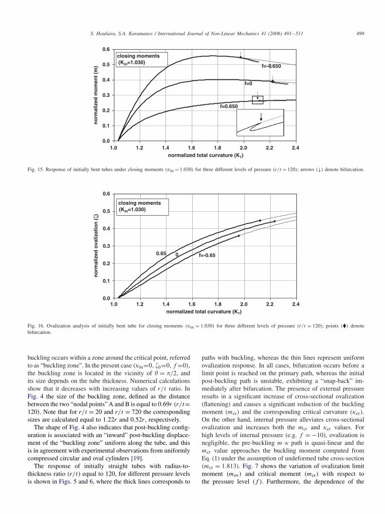
Fig. 17. Pre-buckling and post-buckling shapes of tube’s cross-section for three pressure levels (in = 1.030, r/t = 120); (a) and (b) f = 0, critical point� ≈ �/3; (c) f = 0.65, critical point � = −�/2; (d) f = −0.65, critical point � = �/2.
corresponding normalized curvature values (ov and cr) on thepressure level f is plotted in Fig. 8, and indicates that, withincreasing external pressure, the bifurcation point approachesthe ovalization limit point. The dependence of buckling half-wavelength on the level of pressure is plotted in Fig. 9. Thevalue of s for large values of internal pressure (f → −∞)
approaches unity (s → 1), which means that for high inter-nal pressure the buckling wavelength becomes equal to theaxisymmetric-buckling wavelength of a similar elastic cylindersubjected to uniform axial compression. On the other hand, forexternal pressure values close to pcr (f → 1) the half wave-length value approaches infinity (s → ∞). In this case, theovalization mechanism, accentuated by the presence of highexternal pressure, governs tube response.
In Fig. 10, the elastic deformation energy of the tube perunit length is plotted in terms of curvature for an initially non-pressurized straight tube (in = 0, f = 0). The energy is nor-malized by the product of Me and kN. The diagram is initiallymonotonically increasing and exhibits a negative “jump” at thebifurcation curvature. This discontinuity is more pronouncedfor a thin-walled tube (r/t=720), shown in the detail of Fig. 10.Beyond this point, it continues to increase monotonically. Thereason for the discontinuity of the diagram is the “snap-back”of the initial post-bifurcation path immediately after buckling.Note that experimental measurements, as well as molecular dy-namics simulations in elastic carbon nanotubes, have shown asimilar “kink” on the elastic deformation energy diagram [4].
-1
-0.5
0
0.5
1
-1.0 -0.5 0.0 0.5 1.0
no
rmal
ized
dis
tan
ce f
rom
n
eutr
al a
xis
(y/r
)
normalized longitudinal stress (σx/σe)
Fig. 18. Variation of longitudinal stresses at tube cross-section with re-spect to the distance from tube axis just prior to buckling of an ini-tially bent tube under closing bending moments and external pressure(in = 1.030, f = 0.65, r/t = 120).
The bending response of circular initially slightly bent tubes(in = ±0.20) in terms of the pressure level (f ) is shown inFigs. 11–15. Negative and positive values of in correspond toopening and closing bending moments, respectively. For thisvalue of initial curvature, buckling occurs before the ovaliza-tion limit moment, regardless the level of pressure and the post-buckling path is also characterized by a “snap-back”. The nu-merical calculations also show that the “buckling zone” is lo-cated around � = �/2 for both closing and opening moments.

S. Houliara, S.A. Karamanos / International Journal of Non-Linear Mechanics 41 (2006) 491–511 501
0.0
0.5
1.0
1.5
2.0
2.5
-1.4 -1.3 -1.2 -1.1 -1.0 -0.9 -0.8 -0.7 -0.6 -0.5
no
rmal
ized
mo
men
t (m
)
3D analysis
uniform ovalization
0.0
0.5
1.0
1.5
2.0
2.5
3.0
no
rmal
ized
mo
men
t (m
)
3D analysis
uniform ovalization
0.0
0.5
1.0
1.5
2.0
2.5
3.0
no
rmal
ized
mo
men
t (m
)
3D analysis
uniform ovalization
normalized total curvature (KT)
normalized total curvature (KT)
normalized curvature (KT)
-1.4 -1.3 -1.2 -1.1 -1.0 -0.9 -0.8 -0.7 -0.6 -0.5
-1.4 -1.3 -1.2 -1.1 -1.0 -0.9 -0.8 -0.7 -0.6 -0.5
Fig. 19. Response of initially bent tube for opening moments (in = −1.374) (f = 0.5, 0.0, −0.5, and r/t = 120).
The moment-curvature plots in Figs. 11 and 13 indicate thatthe presence of external pressure accentuates cross-sectionalovalization and therefore, reduces the moment capacity mcrand the corresponding critical curvature cr. On the other hand,there is a beneficial effect of internal pressure on the mcr andcr values, due to the significant reduction of cross-sectionalovalization, as shown in Figs. 12 and 14. Note that, in thecase of opening moments (Fig. 14), the tube initially exhibits
reverse ovalization (negative values of �), so that the diame-ter on the plane of bending lengthens and the other principaldiameter shortens (“bulging” ovalization) until the total cur-vature of the tube becomes about half the initial curvaturevalue (T � −|in|/2). Subsequently, “bulging” ovalizationdecreases and, beyond the curvature where the tube becomesstraight (T = + in = 0), cross-sectional “flattening” oc-curs until buckling. The fact that all T.� curves pass from the

502 S. Houliara, S.A. Karamanos / International Journal of Non-Linear Mechanics 41 (2006) 491–511
-0.4
-0.3
-0.2
-0.1
0.0
0.1
-1.4 -1.3 -1.2 -1.1 -1.0 -0.9 -0.8 -0.7 -0.6 -0.5
no
rmal
ized
ova
lizat
ion
(ζ)
f=0.5f=0
opening moments
f=-0.5
normalized total curvature (KT)
(Kin=1.374)
Fig. 20. Ovalization of initially bent tube under opening moments (in = −1.374) for three different levels of pressure (r/t = 120).
buckling zone
buckling zone
(c) (d)
(a) (b)
pre-buckling
pre-buckling
buckling zone
post-buckling post-buckling
pre-buckling
Fig. 21. Pre-buckling and post-buckling shapes of cross-sections for three different pressure levels: (a) and (b) f = 0 critical point � ≈ �/6, (c) f = 0.5 criticalpoint � ≈ �/6, (d) f = −0.5 critical point � ≈ 40◦; (in = −1.374, r/t = 120).

S. Houliara, S.A. Karamanos / International Journal of Non-Linear Mechanics 41 (2006) 491–511 503
0.0
0.2
0.4
0.6
0.8
1.0
1.2
1.4
0.0 0.1 0.2 0.3 0.4 0.5 0.6
no
rmal
ized
mo
men
t (m
)
initially straight tubef=0
ζo=-0.1ζo=0
ζo=0.1
normalized curvature (K)
Fig. 22. Response of initially ovalized tube in the absence of pressure (f = 0,in = 0, r/t = 120).
0.0
0.2
0.4
0.6
0.8
1.0
1.2
1.4
0.0 0.1 0.2 0.3 0.4 0.5 0.6 0.7
no
rmal
ized
mo
men
t (m
)
no
rmal
ized
mo
men
t (m
)
f=0.217
f=0.65
f=0
f=-0.217
f=-0.65initial ovalization (ζo=-0.1)
A
1.02
1.01
1.00
0.99
0.980.515 0.520 0.525 0.530 0.420 0.425 0.430 0.435
normalized curvature (K)
normalized curvature (K) normalized curvature (K)
bifurcation
bifurcation
primary path
primary path
external pressure (f=0.217)initial ovalization (ζo=-0.1)
external pressure (f=0.65)initial ovalization (ζo=-0.1)
0.80
0.79
0.78
0.77
0.76
(a)
(b) (c)
Fig. 23. (a) Bifurcation analysis of intially “bulged” tubes under for five different pressure levels (r/t = 120,in = 0); (b) detail of equilibrium path atbifurcation for f = 0.217; (c) detail of equilibrium path at bifurcation for f = 0.65; arrows (↓) denote bifurcation.
origin (T = � = 0) can be verified from the simplifiedovalization-curvature Eq. (41) of the Appendix.
The response of circular tubes with more pronounced ini-tial curvature (in = 1.030) under closing bending momentsis shown in Figs. 15 and 16. The numerical results indicate
that bifurcation occurs well beyond limit point instability, forall three pressure levels, so that ovalization instability governstube response. In addition, the secondary path under externalpressure (f = 0.65) follows closely the primary equilibriumpath. A closer view of the secondary path for f = 0.65 around

504 S. Houliara, S.A. Karamanos / International Journal of Non-Linear Mechanics 41 (2006) 491–511
-0.3
-0.2
-0.1
0.0
0.1
0.2
0.3
0.4
0.0 0.1 0.2 0.3 0.4 0.5 0.6 0.7normalized curvature (K)
no
rmal
ized
ova
lizat
ion
(ζ+
ζ o)
f=0.2170
-0.65
f=0.65
0.217
A
Fig. 24. Ovalization of initially “bulged” tubes under for five different pressure levels (r/t = 120).
bifurcation is shown in the detail of Fig. 15. The ovalizationresponse of these pressurized tubes (in = 1.030), plotted inFig. 16, indicates that bucking occurs at large values of cross-sectional flattening (�cr > 0.35). The “flattened” cross-sectionalshapes of the buckled tube configurations (Fig. 17), show thatthe wavy pattern also occurs within a small portion of the tubecircumference, verifying the “local” character of buckling alsoobserved in Fig. 4. Nevertheless, the � = �/2 location maynot be critical in all cases. In the absence of pressure (f = 0)
the critical point is located at about � ≈ �/3 (Figs. 17a, b).In the presence of external pressure (f = 0.65) the numeri-cal results indicated that the buckling zone is located at the“extrados” of the cross-section (� = −�/2), as shown in Fig.17c. This is explained by the compressive longitudinal stressesat � = −�/2, depicted in the detail of Fig. 18, in conjunc-tion with the flat shape of the ovalized cross-section at thislocation.
The response of an initially curved tube subjected to open-ing bending moments (in = −1.374) is shown in Figs. 19 fordifferent pressure levels. In all three cases buckling occurs be-fore a limit point is reached. Furthermore, buckling occurs be-fore the tube becomes straight (T < 0), as shown in Fig. 20,and the corresponding post-buckling tube response exhibits avery sharp “snap-back”. The buckled tube cross-sections withina half-wavelength are depicted in Fig. 21, and show that forthe three pressure levels, the buckling zone is no longer in thevicinity of � = �/2. Also note that the externally pressurizedcase corresponds to the most pronounced bulging ovalization.
Finally, the effects of initial cross-sectional ovality on thebuckling moment are examined, considering a relatively smallstress-free doubly-symmetric out-of-roundness of the tubecross-section, which is assumed constant along the tube
w0(�) = 0 cos 2�, (10)
v0(�) = −0
2sin 2�. (11)
The above expressions correspond to a “first-order inextensional”ovalization deformation ((dv0/d�) + w0 = 0). Using the oval-ization definition of Eq. (9), the ovalization parameter has aninitial value �0 equal to 0/r . The effects of such an imper-fection on the bending response of an initially straight tube(in = 0) are shown in Fig. 22 for zero pressure (f = 0), andfor relatively small initial ovality |�0|�0.1. Positive valuesof initial ovalization correspond to “initial flattening” of thetube’s cross-section, whereas negative values refer to “initialbulging”. The results of Fig. 23 a demonstrate that the orien-tation of the initial out-of-roundness may be quite important,especially in the presence of external pressure (f > 0). Inparticular, reverse initial ovality, combined with external pres-sure, results in a post-buckling path that follows closely theprimary equilibrium path (Figs. 23b, c). In Fig. 23, all the m.curves, regardless the pressure level, pass through a commonpoint A (mA = 0.945 and A = 0.306) located before thebifurcation point. Furthermore, at this value of curvature thecorresponding cross-sectional ovalization is zero (point A inFig. 24). The above values of mA and A can be also verifiedby the simplified analytical ovalization solution presented inthe Appendix; requiring � + �0 = 0 and in = 0 in Eqs. (41)and (42), one readily obtains = |�0|1/2 and m = �|�0|1/2,and that for �0 = −0.1 those values are very close to mA
and A.
4. Simplified analytical solution
Simplified bifurcation analyses for shells have been proposedin previous works based on the assumption that buckling isfully determined by the stress and deformation inside the zoneof the initial buckle, and that stresses and curvatures inside thatzone are constant [9,12,15,20,21]. Under this assumption, anexpression similar to Eq. (2) can be obtained, which governsshell instability at each point around the circumference. Thelocal character of buckling around the cross-section shown in
S. Houliara, S.A. Karamanos / International Journal of Non-Linear Mechanics 41 (2006) 491–511 505
critical point
deformed
undeformed
X
Y
rθ(θ) θ
Fig. 25. Local coordinates X and Y are defined on the buckling zone area.
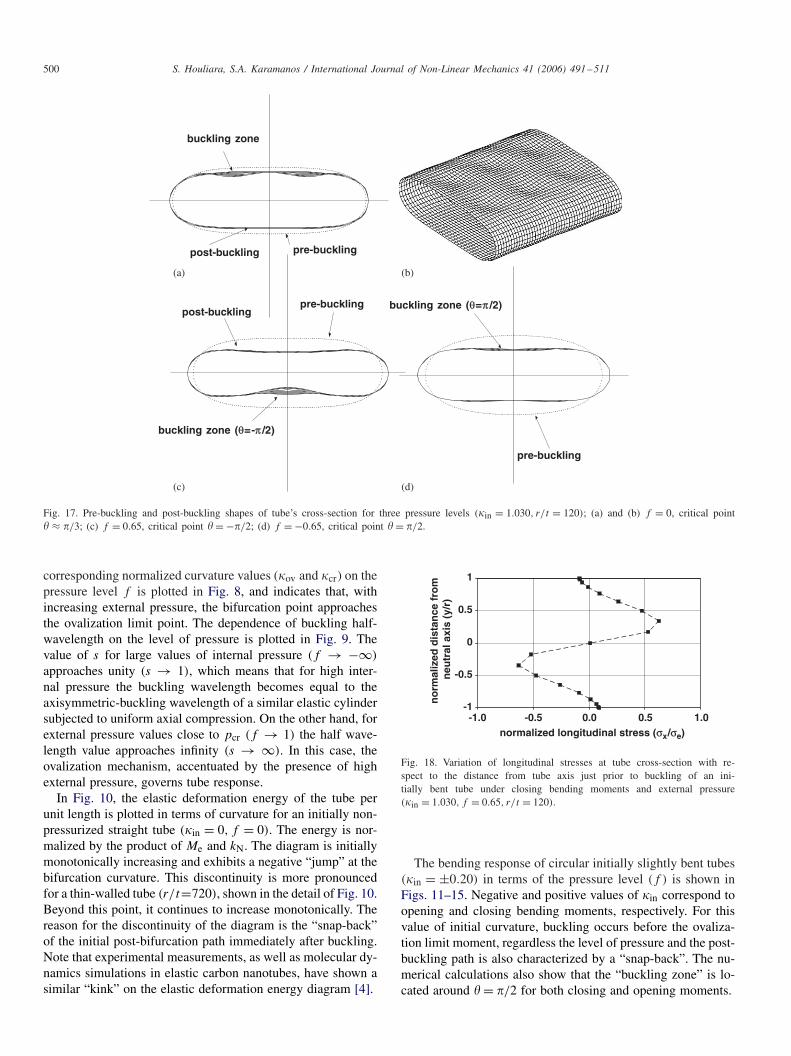
Figs. 4, 17, 21 provide good evidence for the validity of theabove assumption. In the present work, the above concept isoutlined, and it is further elaborated to obtain closed-form ana-lytical expressions for the bifurcation curvature cr and momentmcr, as well as for the corresponding buckling wavelength s.
4.1. Linearized shell equations
Local coordinates X and Y are defined on the buckling zonearea, denoting the distances from the center of the bucklingzone, in the longitudinal and the hoop direction, respectively,(Fig. 25). Starting from the non-linear DMV equations
Et3
12(1 − �2)∇4W − 1
Rx
Nx − 1
Ry
Ny
+ 2Nxy
�2W
�X�Y= p(X, Y ), (12)
1
Et∇4F − 1
Rx
(�2W
�Y 2
)− 1
Ry
(�2W
�X2
)− �2W
�X2
�2W
�Y 2
−(
�2W
�X�Y
)2
= 0, (13)
where W and F are the displacement and stress functions,respectively, Nx, Ny, Nxy are the membrane stress resultants(equal to the second derivatives of the stress function F), 1/Rx ,1/Ry are the local curvatures of the deformed tube, and follow-ing the linearization procedure described in [21], the linearizedform of Eqs. (12) and (13) is obtained as follows:
[(�2x + �2
y)4 + 1
Eth0 (Nx�2x + Ny�
2y − 2Nxy�x�y)(�
2x + �2
y)2
+ (kx�2y + ky�
2x − 2kt r�0�x�y)
2]w̃ = 0, (14)
where w̃(x, y) is a small deviation of the radial displacementfrom the pre-buckling state, x and y are dimensionless local
coordinates, so that
x = X/c, y = Y/c, c = √r�0t/
4√
12(1 − �2), (15)
�x, �y denote partial derivatives with respect to x and y,
h0 = t
r�0
√12(1 − �2)
, kx = r�0
Rx
, ky = r�0
Ry
(16)
kt is the “torsion” of the deformed tube surface and 1/r�0 isthe deformed (ovalized) cross-sectional curvature at the middleof the buckling zone (x = y = 0). In Eqs. (14)–(16), the stressresultants Nx, Ny, Nxy and the curvatures 1/Rx, 1/Ry, 1/r�0should be computed at the deformed pre-buckling state.
Assuming constant deformation and stress within the buck-ling zone, as well as symmetry of the pre-buckling state withrespect to the plane of bending, Nx, Ny, kx are constant, ky =1, Nxy = 0 and kt = 0. In addition, a wave-type solution of Eq.(14) is considered, with no variation in the hoop direction:
w̃ = w̃(x) = A cos nx, (17)
where A is an arbitrary constant and n is a dimensionless wave-length parameter. Substituting Eq. (17) into the linearized buck-ling Eq. (14), the requirement of non-trivial solution dictatesthat the following expression should hold at the bifurcationstage within the buckling zone:
Nx = Et2
r�0
√12(1 − �2)
[n2 + 1
n2
]. (18)
It is noted that a more general form of Eq. (18), consideringtrigonometric variation in both directions x and y, is reportedin [21]. Minimization of Nx in Eq. (18) with respect to n givesn = 1, or equivalently,
Lhw = �c
n= �
[12(1 − �2)]1/4
√r�0t (19)
and Eq. (18) becomes
�x0 = E√3(1 − �2)
(t
r�0
), (20)
where �x0 is the longitudinal buckling stress within the bucklingzone. Eq. (20) resembles Eq. (2), and implies that the tubebuckles at the location where stress �x0 becomes equal to thebuckling stress of a uniformly compressed circular cylinder,with radius equal to the current hoop radius r�0 at the criticallocation.
4.2. Closed-form solution
In the present study, Eq. (20) is further elaborated to ob-tain a closed-form expression for the bifurcation curvature. Theanalysis is limited to tubes with relatively small initial curva-ture and initial ovality, so that buckling occurs at � = �/2. Thekey step in the development of the closed-form solution is con-sideration of the simplified ovalization solution presented inthe Appendix, to describe the pre-buckling state. In particular,the local hoop curvature 1/r�0 and the longitudinal stress �x0at � = �/2 at the ovalized pre-buckling configuration can be

506 S. Houliara, S.A. Karamanos / International Journal of Non-Linear Mechanics 41 (2006) 491–511
-1.5
-1.0
-0.5
0.0
0.5
1.0
0.2 0.4 0.6 0.8 1.0 1.2 1.4
normalized critical moment (mcr)
no
rmal
ized
pre
ssu
re (
f)
r/t=120
r/t=480
r/t=720
analytical
Fig. 26. Variation of critical moment with respect to the pressure level; comparison between numerical results for three different r/t ratios and analytical solution.
-1.5
-1.0
-0.5
0.0
0.5
1.0
0.15 0.20 0.25 0.30 0.35 0.40 0.45 0.50
no
rmal
ized
pre
ssu
re (
f)
r/t=120
r/t=480
r/t=720
analytical
normalized curvature (Kcr)
Fig. 27. Variation of critical curvature with respect to the pressure level; comparison of numerical results for three different r/t ratios with analytical solution.
-1.5
-1.0
-0.5
0.0
0.5
1.0
1.0 1.2 1.4 1.6 1.8 2.0 2.2 2.4
no
rmal
ized
pre
ssu
re (
f)
r/t=120
r/t=480
r/t=720
analytical
normalized half wavelength (s)
Fig. 28. Variation of buckling wavelength with respect to the pressure level; comparison of numerical results for three different r/t ratios with analytical solution.

S. Houliara, S.A. Karamanos / International Journal of Non-Linear Mechanics 41 (2006) 491–511 507
0.0
0.2
0.4
0.6
0.8
1.0
1.2
1.4
-0.2 0.0 0.2 0.4 0.6 0.8 1.0
no
rmalized
mo
men
t (m
)
3D analysis (numerical)
uniform ovalization (numerical)
uniform ovalization (analytical)
normalized total curvature (KT)
Fig. 29. Comparison of numerical results and analytical solutions for non-pressurized tubes (r/t = 120) and for three different values of initial curvature(in = 0,in = ±0.2); arrows (↓↑) denote the critical points obtained from the analytical solution.
0.0
0.2
0.4
0.6
0.8
1.0
1.2
1.4
1.6
1.8
-0.4 -0.2 0.0 0.2 0.4 0.6 0.8 1.0 1.2normalized total curvature (KT)
no
rmal
ized
mo
men
t (m
)
3D analysis(numerical)uniform ovalization(numerical)uniform ovalization(analytical)
Fig. 30. Comparison of numerical results and analytical solutions for non-pressurized tubes (r/t = 120) and for two different values of initial curvature(in = ±0.343); arrows (↓↑) denote the critical points obtained from the analytical solution.
approximated from Eqs. (43), (44) as follows:
1
r�0= 1
r�(�/2)= −3�0 + 1 − f − 3( + in)
r(1 − f ), (21)
�x0 = �x(�/2) = E√1 − �2
(t
r
)[−�0
+ f in
1 − f
+
(1 − ( + in)
2
1 − f
)]. (22)
Substituting the above expressions for 1/r�0 and �x0 in thebuckling Eq. (20), a third-order algebraic equation is obtainedin terms of the critical curvature cr:
cr
(1 − (cr + in)
2
1 − f
)− 1√
3
(1 − 3cr(cr + in)
1 − f
)
− �0cr + f in
1 − f+ √
3�0
1 − f= 0 (23)
which has the following closed-form solution
cr = 1√3
− 2in
3+ 2
3
√abs[3(2 − f ) − √
3in + 2in − 3�0]
× cos
(�
3+ 1
3arccos
[1
2
3√
32in − 23
in + 6√
3(1 − 6�0) + 9in(3 − 2�0 + f (3 − 2�0))
abs[3(2 − f ) − √3in + 2
in − 3�0]3/2
]), (24)
508 S. Houliara, S.A. Karamanos / International Journal of Non-Linear Mechanics 41 (2006) 491–511
where abs[ ] is the absolute value of [ ]. Subsequently, the bifur-cation moment mcr is obtained from Eq. (42) of the Appendixas follows:
mcr = − 3
4�0�
(2 + f in
1 − f
)
+ cr�
(1 − 3(cr + in)(2cr + in)
4(1 − f )
). (25)
Expressions (24) and (25) define the bifurcation point on theprimary m. path of equation. Furthermore, Eqs. (19) and (21)lead to the following closed-form expression for the normalizedhalf wavelength:
s =√
(1 − f )
−3�0 + (1 − f ) − 3cr(cr + in). (26)
For the particular case of initially straight pressurized tubeswithout initial ovality (in = 0 and �0 = 0), Eq. (23) becomes
cr
(1 − 1
1 − f2
cr
)− 1√
3
(1 − 3
1 − f2
cr
)= 0 (27)
and its solution is written in closed form as follows:
cr = 1√3
+ 2
3
√abs[3(2 − f )]
× cos
(�
3+ 1
3arccos
[3√
3
abs[3(2 − f )]3/2
]). (28)
Furthermore, the expression for the corresponding normalizedhalf-wave length becomes:
s = Lhw
L0=√
r�0
r=√
(1 − f )
1 − f − 32cr
. (29)
Nx
Nx
-0.75 -0.50 -0.25 0.00 0.25 0.50 0.75normalized transverse displacement (�/r )
-1.0
-0.5
0.0
0.5
1.0
no
rmal
ized
tra
nsv
erse
fo
rce
(Q/Q
0)
= 0.25Q
− 0.250.0
Q
�in
�<0
�in�in/r
�>0
flattening
bulging
circularinitialdeformed
(a) (b)
Fig. 31. (a) Simple mechanical model, simulating buckling of tubular shells under axial compression [22]. (b) Response of circular and initially oval archesunder a concentrated load on the crest; results from shell finite element analysis [23]. Negative values of �in indicate initial ovality opposite to the one shownin the sketches.
The accuracy of cr and mcr values, obtained from the aboveanalytical equations, are shown in Figs. 26, 27, 28 for circularinitially straight tubes, together with numerical results, indicat-ing a remarkable accuracy. The agreement is better in the caseof thin-walled tubes (large values of r/t), because those tubesexhibit a smaller size of buckling zone, as discussed in the pre-vious section. The comparison between the numerical resultswith the analytical solution shows that the above closed-formexpressions are quite accurate for relatively small values of inand �0, as shown in Figs. 29 and 30. In those figures, Eq. (42)is used to express the pre-buckling analytical solution, and thebifurcation point, (denoted by the arrows (↓↑) is obtained fromEqs. (24) and (25). For the particular case of zero initial oval-ity (�0 = 0) the expressions provide very good accuracy when−0.4�in �0.2.
5. Discussion
A simple model depicted in Fig. 31 a, provides a physicalexplanation of the numerical and analytical results, reportedin the previous sections. The model was proposed in an earlypublication [22] for cylindrical shells under uniform axial com-pression. According to this model, the tube is considered as a“bundle” of compressed longitudinal strips in the longitudinaldirection, each one supported by a series of springs, so that theproblem under consideration is similar to the buckling problemof a beam on elastic foundation. The “foundation springs” areelastic arches, representing the stiffness provided by the hoopdeformation of the shell.
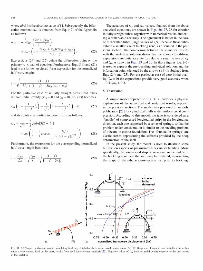
In the present study, the model is used to illustrate somebifurcation aspects of pressurized tubes under bending. Morespecifically, the compressed strip is considered in the middle ofthe buckling zone, and the arch may be ovalized, representingthe shape of the tubular cross-section just prior to buckling.
S. Houliara, S.A. Karamanos / International Journal of Non-Linear Mechanics 41 (2006) 491–511 509
Arch stiffness plays a key role on the buckling stress and thecorresponding wavelength, and depends on the amount of oval-ization. In Fig. 31b, the response of elastic arches under a singleconcentrated load on the crest is plotted. Three cases are consid-ered, corresponding to initially non-ovalized (circular) initially“flattened” and initially “bulged” tubes, denoted as cases A, Band C, respectively. The results are obtained numerically, us-ing a non-linear degenerated shell finite element analysis [23].In those results, the “flattening” direction of the load is con-sidered positive. In all three cases, the response is non-linear“softening/hardening”, resulting in an unstable post-bucklingpath for the compressed strip, as discussed in [24]. Fig. 31b alsoshows that the support-arch stiffness is significantly reduced inthe initially “flattened” arch (case B), but it is quite higher inthe initially “bulged” arch (case C).
The above model can illustrate some aspects of tube bifur-cation under the combined action of bending and pressure. Inthe case of closing bending moments, the cross-section flattensaround the critical location, reduces the stiffness of the sup-porting arches, and results in a decrease of the critical moment,as shown in Figs. 11 and 15. The reduction of support stiffnessis accentuated in the presence of external pressure, whereasinternal pressure reduces flattening, increasing the stiffness ofthe supports and the corresponding critical longitudinal stress.Similarly, the presence of initial curvature opposite to the di-rection of bending (opening moments), increases the local hoopcurvature, resulting in larger support stiffness, and therefore, itcorresponds to a shorter wavelength and a higher critical mo-ment, also depicted in Figs. 13 and 19.
6. Conclusions
In the present paper, the non-linear response of long pressur-ized thin-walled elastic tubes is examined, through a special-purpose, “tube” finite element formulation. The effects of pres-sure (internal and/or external), initial curvature and initial oval-ity, as well as the influence of the radius-to-thickness ratio areinvestigated. The results show that the response is governedby the strong interaction of cross-sectional ovalization, whichcharacterizes the non-linear pre-buckling path, and bifurcationinstability, in the form of uniform wrinkles along the tube. Onthe other hand, in the circumferential direction, buckling occurswithin a limited region, called the “buckling zone”.
For circular, initially straight tubes, buckling occurs prior toovalization instability, regardless the pressure level, the buck-ling zone is located at �=�/2, and bifurcation is followed by a“snap back” of the post-buckling (secondary) equilibrium path,which is more pronounced in the case of thin-walled tubes. Ininitially bent tubes under opening moments (in < 0) bucklingoccurs before ovalization limit point, for any pressure level, fol-lowed by a sharp “snap back”. On the other hand, for closingmoments (in > 0) buckling may occur prior or beyond oval-ization limit point depending on the value of initial curvature(in).
Generally, the presence of external pressure results in a re-duction of the buckling moment and the corresponding buck-ling curvature, and increases the buckling wavelength value.
On the other hand, the presence of internal pressure reducescross-sectional ovalization, increases the buckling moment anddecreases the corresponding wavelength. The effects of rela-tively small initial ovality are also examined in the presenceof pressure. It is demonstrated that the orientation of initialovality may have a significant influence. For the case of initial“flattening”, bifurcation occurs before a limit point is reachedon the primary path, whereas for the case of initial “bulging”,bifurcation may occur prior or beyond the limit point depend-ing on the pressure level.
A simplified analytical bifurcation solution is also presented,which results in closed-form expressions for the critical cur-vature, the critical moment and the corresponding bucklingwavelength of thin-walled elastic tubes subjected to pressur-ized bending. The analytical formulation is based on the lin-earized DMV shell equations, employs the ovalization solution,presented in the Appendix, to describe the pre-buckling state,and uses the assumption that stress and deformation are con-stant within the buckling zone. The closed-form expressionsprovide results of remarkable accuracy with respect to the fi-nite elements results, for relatively small values of initial cur-vature. Furthermore, the predictions of the closed-form expres-sions are closer to the numerical results for thin-walled tubes.Finally, the post-buckling behavior of elastic tubes is studiedusing a simple mechanical model, proposed elsewhere, and theeffects of ovalization and pressure are illustrated in an elegantmanner.
Acknowledgement
The present work was supported by a Fellowship fromthe Alexander S. Onassis Public Benefit Foundation, Athens,Greece, awarded to S. Houliara.
Appendix. Closed-form ovalization solution
It is possible to derive a simplified closed-form ovalizationsolution that accounts for the effects of initial curvature, initialovality and pressure, using a simple variational approach, whichis described in this Appendix. The formulation considers thepotential energy per unit length, expressed as follows:
� = UL + UC + VP − WP − Mk, (30)
where UL is the longitudinal strain energy, UC is the cross-sectional (hoop) strain energy due to ovalization, VP is thepressure potential and WP is the second-order work of hooppressure stress (�p = pr/t). The longitudinal strain energy ULis expressed in terms of longitudinal stress �x and strain x :
UL = 1
2
∫A
�x x dA = E
2
∫A
2x dA = Etr
2
∫ 2�
0 2x d�, (31)
where A is the tube cross-section (A = 2�rt),
x = ky + un
R= k[(r + w0 + w) sin � + (v0 + v) cos �]
+ 1
R[v cos � + w sin �]. (32)

510 S. Houliara, S.A. Karamanos / International Journal of Non-Linear Mechanics 41 (2006) 491–511
In the above expression, y is the distance from the neutralaxis, and un is the displacement in the direction of the planeof bending. The initial ovality of the cross-section is describedby stress-free displacements w0(�) and v0(�) in the radial andthe tangential direction, respectively. The additional radial andtangential displacements are described by w(�) and v(�), re-spectively. The hoop strain is
� = �m + k�� =[
1
r(v′ + w)
]+[
1
r2 (v′ − w′′)]
�, (33)
where �m is the membrane hoop strain, k� is the change ofhoop curvature, and ( )′ denotes differentiation with respect to�, so that
UC = 1
2
∫ t/2
−t/2
∫ 2�
0�� �r d� d�
= 1
2
Er
(1 − �2)
∫ t/2
−t/2
∫ 2�
0 2� d� d� (34)
It is readily shown [8] that the pressure potential VP is
VP = p�A = p(A∗ − A0), (35)
where A∗ is the area enclosed by the deformed ring
A∗ = �r2 + 1
2
∫ 2�
0(2rw + v2 + v′w − vw′ + w2) d�, (36)
where A0 is the area enclosed by the initially ovalized ring,equal to �r2, and external pressure p is assumed positive.
The second-order work of hoop pressure stress (�p=pr/t) is
WP =∫ 2�
0
pr
t �mrt d�
= 1
2p
∫ 2�
0((v0 + v) − (w0 + w)′)2 d�, (37)
where �m = ( 12 )[((v0 + v) − (w0 + w)′)/r]2 is the non-linear
part of the membrane hoop strain. A simple “inextentional”Ritz-type solution for w(�) and v(�) is assumed
w(�) = cos 2� and v(�) = −
2sin 2� (38)
which may be considered as a simplified version of expansions(4) and (5), with a2 =−2b2 and all other ovalization parametersequal to zero. The initial ovality of the tube’s cross-section isalso assumed “inextentional” in the form of Eqs. (38)
w0(�) = 0 cos 2� and v0(�) = −0
2sin 2�. (39)
In Eqs. (38) and (39) 0 and are the initial and the additionalovalization amplitude, respectively.
Neglecting the quadratic terms of in UL, and consideringEqs. (38) and (39) one obtains
�(, k) = E�rt
2
(k2r2 − 3
2kr(( + 0)k + kin)
)
+ 3
8
E�t32
(1 − �2)r3 − 3
8p�(3( + 0)
2
+ ( + 20)) − Mk. (40)
Minimization of � results in the following expressions:
� =
r= �0f
1 − f+ ( + in)
1 − f, (41)
where � is the normalized ovalization in the tube’s cross-sectionadditional to the initial one (so that �T = �0 + �), and
m = −�0�3(2 + in)
4(1 − f )+ �
[1 − 3( + in)(2 + in)
4(1 − f )
](42)
that describes the primary path (uniform ovalization), consider-ing the effects of pressure, initial curvature and initial ovality.Using Eqs. (39) and (41), closed-form expressions for the lon-gitudinal stress (�x = E x) and for the hoop curvature at thedeformed configuration (1/r�) are readily obtained
�x(�)
�e= − �0
− 2f − f in
4(1 − f )(3 sin � − sin 3�)
+
[(1−3(+in)
2
4(1−f )
)sin �+ (+in)
2
4(1−f )sin 3�
],
(43)
1
r�(�)= 1
r+ 3�0(1 − 2f )
r(1 − f )cos 2� + 3( + in)
r(1 − f )cos 2�. (44)
Expressions (41)–(44) account for initial ovality, initial cur-vature and pressure. For zero initial ovality (�0 = 0) are sim-ilar to those derived in [25] for slightly bent tubes, using anasymptotic approximation of the non-linear ring equations. Fur-thermore, for the special case of zero initial ovality and zeropressure (�0 = 0, f = 0), a moment-curvature equation quitesimilar to Eq. (42) was derived in [26]. Expressions (41)–(44)compare quite well with numerical results up to the ovaliza-tion limit point of tubes, with relatively small initial curvature(−0.4�in �0.2), as shown in Figs. 29 and 30, and can beused to describe the non-linear pre-buckling state in a simpleand efficient manner in the case of thin-walled elastic tubes.More accurate semi-numerical solutions for ovalization bend-ing of elastic tubes have been reported in [25–27] and, morerecently, in [28].
References
[1] L.G. Brazier, On the flexure of thin cylindrical shells and other “thin”sections, Proc. R. Soc. Ser. A 116 (1927) 104–114.
[2] S. Ijima, C. Bradec, A. Maiti, J. Bernholc, Structural flexibility of carbonnanotubes, J. Chem. Phys. 104 (5) (1996) 2089–2092.
[3] T. Vodenitcharova, L.C. Zhang, Mechanism of bending with kinking ofa single-walled carbon nanotubes, Phys. Rev. B 69 (2004) 115410.
[4] B.I. Yacobson, C.J. Bradec, J. Bernholc, Nanomechanics of carbon tubes:instabilities beyond linear response, Phys. Rev. Lett. 79 (14) (1996)2511–2514.
[5] P. Seide, V.I. Weingarten, On the buckling of circular cylindrical shellsunder pure bending, J. Appl. Mech. ASME 28 (1961) 112–116.
[6] J. Kempner, Y.N. Chen, Buckling and Initial Post-buckling of OvalCylindrical Shells under Combined Axial Compression and Bending,Transactions of the New York Academy of Sciences, 1974, pp. 171–191.
[7] B. Budiansky, J.W. Hutchinson, Dynamic Buckling and Imperfection-Sensitive Structures, in: Congress of Applied Mechanics, Munich,Springer, Berlin, 1964, pp. 636–651.

S. Houliara, S.A. Karamanos / International Journal of Non-Linear Mechanics 41 (2006) 491–511 511
[8] D.O. Brush, B.O. Almroth, Buckling of Bars, Plates, and Shells,McGraw-Hill, New York, 1975.
[9] E.L. Axelrad, Refinement of buckling-load analysis for tube flexure byway of considering precritical deformation, Izvestiya Akademii NaukSSSR, Otdelenie Tekhnicheskikh Nauk, Mekhanika i Mashinostroenie 4(1965) 133–139 (in Russian).
[10] F.A. Emmerling, Nichtlineare Biegung und Beulen von Zylindern undkrummen Rohren bei Normaldruck, Ingenieur–Archiv 52 (1982) 1–16(in German).
[11] W.B. Stephens, J.H. Starnes Jr., B.O. Almroth, Collapse of longcylindrical shells under combined bending and pressure loads, AIAA J.13 (1) (1975) 20–25.
[12] O. Fabian, Collapse of cylindrical, elastic tubes under combined bending,pressure and axial loads, Int. J. Solids Struct. 13 (1977) 1257–1270.
[13] J. Fitch, The buckling and post-buckling behavior of spherical caps underconcentrated load, Int. J. Solids Struct. 4 (1968) 421–446.
[14] G.T. Ju, S. Kyriakides, Bifurcation and localization instabilities incylindrical shells under bending II: predictions, Int. J. Solids Struct. 29(1992) 1143–1171.
[15] S.A. Karamanos, Bending instabilities of elastic tubes, Int. J. SolidsStruct. 39 (8) (2002) 2059–2085.
[16] S.A. Karamanos, J.L. Tassoulas, Tubular members I: stability analysisand preliminary results, J. Eng. Mech. ASCE 122 (1) (1996) 64–71.
[17] A. Needleman, Finite elements for finite strain plasticity problems, in:E.H. Lee, R.L. Mallet (Eds.), Plasticity of Metals at Finite Strain: Theory,Experiment and Computation, Rensselaer Polytechnic Institute, Troy,New York, 1982, pp. 387–436.
[18] M.A. Crisfield, An arc-length method including line searches andaccelerations, Int. J. Numer. Meth. Eng. 19 (1983) 1269–1289.
[19] P.C. Tennyson, Buckling of circular cylindrical shells in compression,AIAA J. 2 (7) (1964) 1351–1353.
[20] B. Tatting, Z. Gürdal, V. Vasiliev, Nonlinear response of long orthotropictubes under bending including the Brazier effect, AIAA J. 34 (9) (1996)1934–1940.
[21] E.L. Axelrad, On local buckling of thin shells, Int. J. Nonlinear Mech.20 (4) (1985) 249–259.
[22] T. Von Kármán, G. Dunn, H. Tsien, The influence of curvature on thebuckling characteristics of structures, J. Aeronaut. Sci. 7 (7) (1940)276–289.
[23] S.A. Karamanos, Stability of pressurized long inelastic cylinders underradial transverse loads, Comput. Mech. 18 (6) (1996) 444–453.
[24] Z.P. Bazant, L. Cedolin, Stability of Structures: Elastic, Inelastic, Fractureand Damage Theories, Oxford University Press, Oxford, 1991.
[25] E. Reissner, On finite bending of pressurized tubes, J. Appl. Mech.ASME 26 (1959) 386–392.
[26] J.T. Boyle, The finite bending of curved pipes, Int. J. Solids Struct. 17(1981) 515–529.
[27] E.L. Aksel’rad (Axelrad), Flexure and instability of thin-walledpressurized tubes, Izvestiya Akademii Nauk SSSR, OtdelenieTekhnicheskikh Nauk, Mekhanika i Mashinostroenie 1 (1962) 98–114(in Russian).
[28] S.V. Levyakov, Equations of finite bending of thin-walled curvilineartubes, J. Appl. Mech. Tech. Phys. 52 (5) (2001) 898–901.