Buckling Analysis of Spent Fuel Basket
61
NUREG/CR-6322 UCRL-ID-119697 Buckling Analysis of Spent Fuel Basket Manuscript Completed: February 1995 Date Published: May 1995 Prepared by A. S. Lee, S. E. Bumpas Lawrence Livermore National Laboratory P.O. Box 808 Livermore, CA 94551 Prepared for Division of Industrial and Medical Nuclear Safety Office of Nuclear Material Safety and Safeguards U.S. Nuclear Regulatory Commission Washington, DC 20555-0001 NRC Job Code A0291 ..-S^j,*. .fr„/,„ v DISTRIBUTION OF THIS DOCUMENT iS UNLIMITED
Transcript of Buckling Analysis of Spent Fuel Basket

NUREG/CR-6322 UCRL-ID-119697
Buckling Analysis of Spent Fuel Basket
Manuscript Completed: February 1995 Date Published: May 1995
Prepared by A. S. Lee, S. E. Bumpas
Lawrence Livermore National Laboratory P.O. Box 808 Livermore, CA 94551
Prepared for Division of Industrial and Medical Nuclear Safety Office of Nuclear Material Safety and Safeguards U.S. Nuclear Regulatory Commission Washington, DC 20555-0001 NRC Job Code A0291
. . - S ^ j , * . . f r „ / , „ v
DISTRIBUTION OF THIS DOCUMENT iS UNLIMITED

DISCLAIMER
This report was prepared as an account of work sponsored by an agency of the United States Government. Neither the United States Government nor any agency thereof, nor any of their employees, make any warranty, express or implied, or assumes any legal liability or responsibility for the accuracy, completeness, or usefulness of any information, apparatus, product, or process disclosed, or represents that its use would not infringe privately owned rights. Reference herein to any specific commercial product, process, or service by trade name, trademark, manufacturer, or otherwise does not necessarily constitute or imply its endorsement, recommendation, or favoring by the United States Government or any agency thereof. The views and opinions of authors expressed herein do not necessarily state or reflect those of the United States Government or any agency thereof.
DISCLAIMER
Portions of this document may be illegible in electronic image products. Images are produced from the best available original document.

ABSTRACT
The basket for a spent fuel shipping cask is subjected to compressive stresses that may cause global instability of the basket assemblies or local buckling of the individual members. Adopting the common buckling design practice in which the stability capacity of the entire structure is based on the performance of the individual members of the assemblies, the typical spent fuel basket, which is composed of plates and tubular structural members, can be idealized as an assemblage of columns, beam-columns and plates. This report presents the flexural buckling formulas for five load cases that are common in the basket buckling analysis: column under axial loads, column under axial and bending loads, plate under uniaxial loads, plate under biaxial loadings, and plate under biaxial loads and lateral pressure. The acceptance criteria from the ASME Boiler and Pressure Vessel Code are used to determine the adequacy of the basket components. Special acceptance criteria are proposed to address the unique material characteristics of austenitic stainless steel, a material which is frequently used in the basket assemblies.
- in - NUREG/CR-6322

TABLE OF CONTENTS
ABSTRACT ...iii
LIST OF FIGURES vii
LISTS OFTABLES viii
LIST OF SYMBOLS ix
ACKNOWLEDGEMENTS xi
EXECUTIVE SUMMARY xiii
1.0 INTRODUCTION 1
1.1 Background 1
1.2 Objective..... , 1
1.3 Approach 1
2.0 TYPICAL SPENT FUEL BASKET COMPONENTS 4
3.0 LOADING CONDITIONS 6
4.0 BUCKLING OF COLUMNS AND PLATES... 7
4.1 Bifurcation Buckling 7
4.2 Influence of Initial Imperfections and Residual Stresses 7
4.3 Material Characteristics of Austenitic Stainless Steel 9
4.4 Inelastic Buckling 12
5.0 CLASSICAL BUCKLING FORMULAS FOR BASKET COMPONENTS 14
5.1 Column under axial loads 14
5.2 Column under axial and bending loads 16
5.3 Plate under uniaxial loads 18
5.4 Plate under biaxial loadings 22
5.5 Plate under biaxial loads and lateral pressure 25
- v - NUREG/CR-6322

TABLE OF CONTENTS
6.0 BUCKLING ACCEPTANCE CRITERIA FOR SPENT FUEL BASKET COMPONENTS 26
6.1 ASME Section III, Subsection NF (Component Supports) 26
6.2 Linear-Type Supports for Normal Conditions of Transport 27
6.21 Axial Compression (NF-3322.1 (c)) 27
6.22 Combined Axial Compression and Bending (NF3322.1 (e)) 27
6.23 Width Ratios (NF3322.2 (d)) 29
6.3 Linear-Type Supports for Hypothetical Accident Conditions 30
6.31 Axial Compression (Appendix F-1334.3) 30
6.32 Combined Axial Compression and Bending (Appendix F-1334.5) 32
6.4 Plate- and Shell-Type Support for Normal Conditions of Transport 33
6.5 Plate- and Shell-Type Support for Hypothetical Accident Conditions 33
6.6 Factors of Safety 33
6.61 Service Level A - axial compression 34
6.62 Service Level D - axial compression 35
7.0 SUMMARY 37
8.0 REFERENCES 39
APPENDIX A Modified Ramberg-Osgood Equation 41
NUREG/CR-6322 - vi -

LISTS OF FIGURES
Figure 1. 3D-grid spent fuel basket (plates) 4
Figure 2. Spent fuel basket with cutouts (plates and rods) 5
Figure 3. Elastic buckling curves for compressed elements with initial imperfections 8
Figure 4. Stress-strain curves for Carbon and Stainless Steels 9
Figure 5. Typical stress-strain curves, types 302 and 304 stainless steels 10
Figure 6. Effective-length K factors for centrally loaded columns with various end conditions 15
Figure 7. Thin plate (axbxh) subjected to uniformly distributed loads along edges x = 0 and x = a 18
Figure 8. Influence of boundary conditions on the buckling coefficients of plates
subjected to in-plane compressive loading 19
Figure 9. Buckling coefficient curves for thin plates with all edges simply supported 20
Figure 10. Thin plate subjected to uniformly distributed loads along all edges 23
Figure 11. Critical stress envelope for a simply supported plate of a/b = 1 under
biaxial loading 24
Figure 12. Critical stress envelope for a plate of a/b = 15 under biaxial loading 24
Figure 13. CRC column curves and ASME design curves 35
Figure 14. Factors of safety for axially compressed members embedded in the ASME Code 36
- vii- NUREG/CR-6322
LISTS OF TABLES
Table 1: Design Mechanical Properties (room temperature) of Stainless
Steel Type 304 11
Table 2: Plasticity Reduction Factors for Stainless Steel 12
Table 3: Values of coefficients Cj , C2, C3, §*, and kc* for axially loaded
thin plate with loaded edges simply supported (v = 0.3) and m = 1 21
Table 4: Width Ratios Requirements 30
Table A1: Coefficient n Used for Modified Ramberg-Osgood Equation 41
Table A2: Plasticity Reduction Factors for Stiffened Elements (Types 201, 301, 304, 316) 42
Table A3: Plasticity Reduction Factors for Unstiffened Elements (Types 201, 301, 304, 316) 42
Table A4: Tangent Moduli for Design of Columns (Types 201,. 301, 304, 316) 43
NUREG/CR-6322 - viii -

LIST OF SYMBOLS
T| = Plasticity reduction factor
V = Poisson's ratio
<|> = Side ratio of plate
< | > * = M i n i m u m side ratio corresponding to min imum buckl ing coefficient kc*
Gcr - Critical buckl ing stress
<Se = Elastic buckl ing stress
<5ie = Inelastic buckl ing stress
Gx Py = Normal stress in the x, y direction, respectively
A = Cross sectional area of member
c = Distance to extreme fiber of beam or column section in bending
Cj.C2.C3 = Coefficients used to calculate buckling coefficients of plates
Cc = Slenderaess ratio separating elastic and inelastic buckl ing
C m = Coefficient applied to bending term in interaction equation and dependent upon co lumn curvature caused by applied moments (Equivalent M o m e n t Factor)
CS = Carbon steel
E = Young's Modulus
Es = Secant Modulus
E, = Tangent Modulus
Fa = Axial compressive stress permitted in the absence of bending moment , ksi
Fb = Bending stress permitted in the absence of axial force, ksi
/„ = Computed axial stress, ksi
fb = Computed bending stress, ksi
Fe = Euler buckling stress
FJ = Euler stress divided by factor of safety, ksi
FSCS = Factors of Safety associated with carbon steel
- i x - NUREG/CR-6322

F$ss = Factors of Safety associated with stainless steel
h = Thickness of thin plate
kc - Buckling coefficient of plate
k* = Minimum buckling coefficient of plate with half wave number m equal to 1
K = Effective length factor
lb = Actual unbraced length in plane of bending, in.
m, n = Half wave numbers
A^, Ny = Normal forces per unit length in plate
P = Applied axial load
PE = Euler buckling load or hinge-ended column
Pe = Elastic critical load
Py = Average yield load, SyA
r = Radius of gyration of member
rh = Radius of gyration about axis of concurrent bending, in.
Sy = Yield strength at temperature, ksi
SS = Stainless steel
NUREG/CR-6322 - x -
ACKNOWLEDGEMENTS
This work was funded by the Transportation Branch, Office of Nuclear Material Safety and Safeguards, under the United States Nuclear Regulatory Commission (NRC). The authors would like to thank Henry W. Lee, technical monitor at the NRC, for his support and guidance. The authors would like to express their deep appreciation to G. C. Mok, T. Lo, and T. A. Nelson of Lawrence Livermore National Laboratory for many stimulating discussions on the subject.
- XI - NUREG/CR-6322

EXECUTIVE SUMMARY
Shipping casks for spent fuel are required to meet the regulations specified in the Code of Federal Regulations, Title 10, Part 71 (10 CFR 71). The baskets which position the spent fuel in the shipping casks are subjected to thermal, pressure, and mechanical loads. The combination of these loadings could induce compressive stresses in the basket that may cause global instability of the basket assemblies or local buckling of the individual members.
The current design methodology for most structural assemblies susceptible to instability is typically based on the performance of the individual members of the structure rather than on the behavior of the entire structure. The usual procedure is to first perform a first order elastic stress analysis of the structure to determine the axial forces and moments in each members. Based on these axial forces and moments, the members are then evaluated and sized according to the buckling acceptance criteria given in an established industrial code such as the ASME Boiler and Pressure Vessel Code. To account for the interaction between the individual members and the uncertainty regarding the true boundary conditions of the members, the "effective length" concept is used. To address the effects of the different end-moment patterns and moment gradient along the member, the "equivalent moment factor" is used in the design.
This simplified "design by members" approach can be used for the buckling analysis of the spent fuel basket assemblies. There are many variations of basket design but all of them essentially are composed of plates and tubular structural members. The basket components, therefore, can be evaluated for their stability capacity by idealizing them as plates, columns, or beam-columns subjected to compressive loadings. Because the basket components are usually not made of structural elements with open cross-section or with wide flange I-beam, torsional buckling or lateral-torsional buckling of the member is unlikely. For this reason, only the flexural buddings of columns, beam-columns, and plates are addressed in the report.
The flexural buckling formulas for five load cases that are common in the basket buckling analysis are presented in the report: column under axial loads, column under axial and bending loads, plate under uniaxial loads, plate under biaxial loadings, and plate under biaxial loads and lateral pressure. Because instability failure may occur in the elastic range or in the plastic range, both elastic and inelastic buckling formulas are identified. Austenitic stainless steel is frequently used for basket components because of its fracture toughness. In contrast to the properties of low-alloy carbon steel, austenitic stainless steel is anisotropic and has a smooth stress-strain curve with a much lower yield point. However, most of these buckling
- xiii - NUREG/CR-6322

formulas were based on research conducted for low alloy carbon steel structural members. For members made of other materials which have different characteristics of carbon steel, the buckling formulas need to be modified. In the case of austenitic stainless steel, the standard buckling formulas are modified by the "plasticity reduction factor".
The acceptance criteria from the ASME Boiler and Pressure Vessel Code are used to determine the adequacy of the basket components. Specifically, the rules in Division I, Section III, Subsection NF - Component Supports and the rules in Appendix F are applicable to the normal transportation conditions and the hypothetical accident conditions specified in 10 CRF 71, respectively. In general, the provisions in Subsection NF and Appendix F are applicable to low alloy carbon steel, so special acceptance criteria are proposed to address the unique material characteristics of the austenitic stainless steel.
NUREG/CR-6322 - X I V -

1.0 INTRODUCTION
1.1 Background
Shipping casks for spent fuel are required to meet the regulations specified in 10 CFR 71 . [ 1 8 ]
The baskets which position the spent fuel in the shipping casks are subjected to thermal, pressure, and mechanical loads. The combination of these loadings could induce compressive stresses in the basket that may cause global instability of the basket assemblies or local buckling of the individual members. In general, buckling of the basket must be prevented because of the criticality issue and the potential hinderance of retrieving the spent fuel from the cask in the event of an accident. While the buckling analysis of cylindrical shells for shipping casks has been addressed in NUREG/CR-4554, "SCANS: Volume 6, Theory Manual, Buckling of Circular Cylindrical Shells" [ 2 5 ], it is desirable to provide a practical reference with all the relevant buckling analysis methods and the acceptance criteria pertaining to the buckling aspects of the shipping cask basket.
1.2 Objective
The objective is to provide a practical engineering reference for the buckling analysis of the spent fuel basket subjected to compressive loadings in a shipping cask. The report will contain the relevant buckling analysis methods for certain selected basket components. Acceptance criteria related to stability and compressive stress from the ASME Boiler and Pressure Vessel Code (B&PV) [ 4 ] are also included. Additional acceptance criteria are proposed for certain conditions which are specific only to the shipping cask basket design and to which the B&PV Code does not provide applicable acceptance criteria.
1.3 Approach
The current design methodology for most structural assemblies susceptible to instability is typically based on the performance of the individual members of the structure father than on the behavior of the entire structure. The usual procedure is to first perform a first order (i.e. equilibrium conditions based on initial undeformed geometry) elastic stress analysis of the structure to determine the axial forces and moments in each members. Based on these axial forces and moments, the members are then evaluated and sized according to the buckling acceptance criteria given in an established industrial code (for example, the B&VP Code). Obviously, the individual members interact with other members and the compressive load in a member will influence the critical buckling load of not only the member itself but also other adjacent members that are connected to the same structural joint. However, it should be noted
- 1 - NUREG/CR-6322
that the individual members are not analyzed purely as isolated elements in this simplified design methodology. To account for the interaction between the structural members and to compensate for the uncertainty regarding the true boundary conditions of the members, the concept of "effective length" is adopted. Clearly, the response of the members depends on the types of loads being applied to the structure. Different loading patterns would cause different types of buckling behaviors in the structural members. To address the effects of the different end-moment patterns and moment gradient along the member, the "equivalent moment factor" is used in the design. This simplified "design by members" approach has proven successful in designing safe structures. For design purposes, this simplified methodology is more practical than carrying out an accurate second order (i.e. equilibrium conditions based on deformed geometry) non-linear limit load analysis for the entire structure.
The approach described above, design by individual members, can be used for the buckling analysis of the spent fuel basket assemblies. There are many variations of basket design but all of them essentially are composed of plates and tubular structural members. The basket components, therefore, can be evaluated for their stability capacity by idealizing them as plates, columns, or beam-columns subjected to compressive loadings. Because the basket components are usually not made of structural elements with open cross-section or with wide flange I-beam, torsional buckling or lateral-torsional buckling of the member is unlikely. For this reason, only the flexural buddings of columns, beam-columns, and plates are discussed.
The buckling phenomena of columns, beam-columns and plates are well documented in the literature. From these references, buckling formulas for different type of loadings for the columns, beam-columns, and plates are compiled. Because instability failure may occur in the elastic range (below the proportional limit) or in the plastic range (above the proportional limit), both elastic and inelastic buckling formulas are identified. Austenitic stainless steel is frequently used for basket components because of its fracture toughness. In contrast to the properties of low-alloy carbon steel, austenitic stainless steel is anisotropic and has a smooth stress-strain curve with a much lower yield point. However, most of these buckling formulas were based on research conducted for low alloy carbon steel structural members. For members made of other materials which have different characteristics of carbon steel, the buckling formulas need to be modified. In the case of austenitic stainless steel, the standard buckling formulas are modified by the "plasticity reduction factor".
Acceptance criteria for the Plate- and Shell-Type support and for the Linear-Type support from the ASME B&PV Code, Division I, Section III, Subsection NF (Component Supports) are used as the acceptance criteria for the basket components. Special acceptance criteria with higher factors of safety for members made of austenitic stainless steel are indicated.
NUREG/CR-6322 - 2 -

The applied loads and the worst load combinations for the basket assemblies are those specified in 10 CFR 71. The loadings are primarily of three types: thermal, pressure, and impact. Determination of the load values to be applied to the basket assemblies are not discussed in this report. It is assumed that a system analysis of the shipping cask has been performed and the forces and moments caused by the worst load combination in the basket assemblies are known. In practice, finite element dynamic analyses are frequently used to determine the equivalent loadings for the various events specified in 10 CFR 71 and for stress evaluation of the shipping cask. But in general, hand calculation is still the prevailing method for assessing the stability of individual members of the basket. The buckling formulas and interaction equations presented in this report may then be utilized.
The post-buckling behavior of the basket assemblies are not discussed in this report. First of all, the deformation of the buckled basket affects the criticality of the spent fuel and also may prohibit quick retrieval of the spent fuel bundles in the event of an accident. Secondly, large deformation in the buckled basket implies high stresses which may have exceeded the stress limits specified in the design codes. For these reasons, the post-buckling strength of the structural elements of the basket should not be utilized in the basket design.
- 3 - NUREG/CR-6322
2.0 TYPICAL SPENT FUEL BASKET COMPONENTS
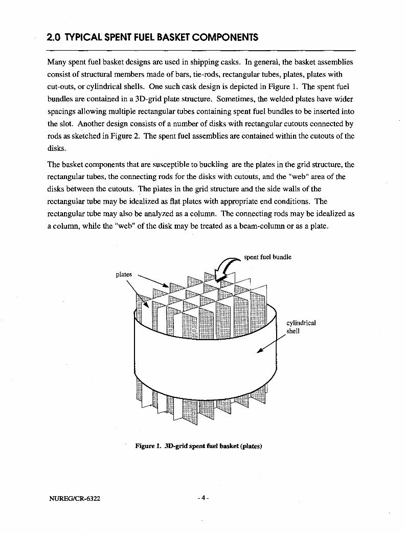
Many spent fuel basket designs are used in shipping casks. In general, the basket assemblies consist of structural members made of bars, tie-rods, rectangular tubes, plates, plates with cut-outs, or cylindrical shells. One such cask design is depicted in Figure 1. The spent fuel bundles are contained in a 3D-grid plate structure. Sometimes, the welded plates have wider spacings allowing multiple rectangular tubes containing spent fuel bundles to be inserted into the slot. Another design consists of a number of disks with rectangular cutouts connected by rods as sketched in Figure 2. The spent fuel assemblies are contained within the cutouts of the disks.
The basket components that are susceptible to buckling are the plates in the grid structure, the rectangular tubes, the connecting rods for the disks with cutouts, and the "web" area of the disks between the cutouts. The plates in the grid structure and the side walls of the rectangular tube may be idealized as flat plates with appropriate end conditions. The rectangular tube may also be analyzed as a column. The connecting rods may be idealized as a column, while the "web" of the disk may be treated as a beam-column or as a plate.
Figure 1. 3D-grid spent fuel basket (plates)
NUREG/CR-6322 - 4 -

Figure 2. Spent fuel basket with cutouts (plates and rods)
The most challenging part of the entire buckling analysis of the basket is probably the process of making the idealization of the members for a given loading condition. The accuracy of the analysis depends primarily on the assumptions made for the idealized members. Each assumption must be considered carefully and must be based on sound structural mechanics principles. The proper boundary conditions for the idealized members are usually uncertain. Often times, two extreme boundary conditions have to be evaluated in order to bound the correct critical load. Similarly, the structural member may have to be analyzed in two different ways to determine the lowest buckling mode. For example, a rectangular tube can be either idealized as a column with a box section for investigating its global buckling behavior, or just treated as a side wall of the tube as a plate for local buckling evaluation. Generally, it is prudent to make conservative assumptions that will lead to the lowest buckling load whenever the boundary conditions are unclear.
- 5 - NUREG/CR-6322

3.0 LOADING CONDITIONS
Transportation casks for radioactive materials must meet the requirements specified in 10 CFR 71 [ 1 8 ] . Specifically, the requirements are (1) Normal Conditions of Transport and (2) Hypothetical Accident Conditions. Besides the thermal and pressure loadings on the cask, the Normal Conditions of Transport requires a free drop of the cask from a height of one to four feet, depending on the weight, while the Hypothetical Accident Conditions require a thirty foot free drop of the cask. The cask should strike the unyielding surface in an orientation that maximum damage of the cask is expected. Typically an end-drop, a side drop, and a few oblique-drop dynamic impact analyses of the cask are needed to determine the maximum damage drop orientation. The inertial forces experienced by the basket components from these dynamic analyses are then combined with other loadings to evaluate the static critical buckling stresses in the basket components. If a quasi-static approach is used for the cask impact analysis, a dynamic amplification factor should be applied to the inertial forces of the basket components.
As discussed later in the section on Buckling Acceptance Criteria for Spent Fuel Basket Components, the acceptance criteria for the normal conditions and the accident conditions are different. The acceptance criteria for the normal conditions are more stringent than the acceptance criteria for the accident conditions. Because of this stringency, the dynamic impact forces from the normal conditions, though smaller than those forces obtained from the accident conditions, may still govern the design of the basket components. Therefore buckling of the basket components should be evaluated for both normal and accident conditions.
It should be noted that the forces and moments to be used in the buckling formulas herein should be the maximum loads resulting from the worst load combinations of the various loadings such as thermal, pressure, and impact loads in a given design condition. Stresses resulting from the constraint of free end displacement of the basket within the shipping cask due to thermal differential expansion should be considered. Stress analyses for the basket assemblies due to these loadings are out of the scope of this report, however, aspects of the impact analysis of the transportation cask can be found in "SCANS: Volume 2, Theory Manual, Impact Analysis" [ 2 4 ].
NUREG/CR-6322 - 6 -

4.0 BUCKLING OF COLUMNS AND PLATES
Buckling of columns and plates has been studied extensively and the literature on these topics is voluminous. Because the theory of instability and the mathematical derivation of various buckling formulas can be found in many excellent textbooks, [ 5 ] [ 6 ] [ 1 2 ] ( l 6 ] and other sources that are listed in the references, the theoretical derivations of the formulas are not repeated in this report. However, a brief overview of some of the issues related to buckling of columns and plates is discussed below.
4.1 Bifurcation Buckling
Instability of a compression member occurs when the member exhausts its capacity to carry additional load and further deformation results in a decrease of load-resisting capacity. The instability phenomenon associated with axially loaded columns, beams, plates, and cylindrical shells is called bifurcation buckling. Usually the compression member is marked by a sudden change in its deformation pattern upon reaching a certain load under bifurcation buckling. The theoretical load computed for a perfectly straight and perfectly centered compression member at which the bifurcation occurs is called the critical load. The critical load can be calculated from an eigenvalue analysis of the compression member. It should be noted that the behavior of the compression member after bifurcation can be obtained only by a large deflection analysis.
4.2 Influence of Initial Imperfections and Residual Stresses
The critical load calculated based on a perfect compression member is not necessarily equal to the collapse or failure load for a real member. A real member may have imperfections that include initial curvature of a member, eccentric loads on an initially straight member, and residual stresses. Residual stresses in structural shapes are caused by uneven cooling after rolling. Welded structures also exhibit tensile residual stresses near the vicinity of the welds. Strain hardening due to cold forming is another form of residual stresses. All these imperfections tend to make the actual failure load lower than the theoretical critical load.
A comparison of the elastic buckling behavior of three perfect and imperfect compression members comprising a slender column, a stiffened thin plate, and a thin-walled cylinder is shown in Figure 3, taken from Reference 11. The thin lines represent the load deflection curves beyond the critical load for the perfect members and the thick lines represent the theoretical behavior for the same members when a given imperfection is assumed. As the degree of imperfection decreases, the critical impefect loads approach the theoretical critical
- 7 - NUREG/CR-6322

1.0
P/Pcr
Lateral deflection initial imperfection
Figure 3. Elastic buckling curves for compressed elements with initial imperfections ^
loads as indicated by the thick lines approaching the thin lines. Note that the critical loads for the perfect column and plate agree reasonably well with the maximum load carried by their imperfect counterparts. Therefore, the theoretical critical load may be used as a basis for the design load for slender columns and thin plates. On the other hand, the maximum load for the imperfect thin-walled cylinder is much lower than the theoretical critical load. Thus, the critical load is not a suitable criterion for the design of thin-walled cylinder. It is noted in Reference 19 that if the initial curvature in a thin plate is large, its post buckling behavior is similar to the buckling of a cylindrical shell.
One can observe in Figure 3 that a buckled plate can carry loads much higher than the critical load but the failure load for a column coincides closely to the critical load. Thus it is rational to impose a higher factor of safety against failure to a slender column than to a thin plate. However, it should be noted that the postbuckling strength of the structural members are not allowed in the basket design of the transportation casks because a severely buckled basket may prohibit prompt removal of the fuel assemblies from the cask after an accident.
The influence of residual stresses and initial imperfections on the strength of columns has been investigated by many researchers. Based on the results of extensive testing of imperfect hot rolled and welded columns, the original Column Research Council (CRC) column design curve t l 4 l and the more recent Structural Stability Research Council (SSRC) multiple design curves [ 1 1 ] are established. These design curves form the basis of the buckling design criteria
NUREG/CR-6322 - 8 -
Thin plate (stiffened)
Slender column
Thin-walled cylinder

found in the AISC [2] and ASME B&VP Code.
4.3 Material Characteristics of Austenitic Stainless Steel
The materials commonly used for the basket components are various types of austenitic stainless steels because of their resistance to brittle fracture. The characteristics of stainless steel are different from carbon steel. Stainless steel has nonlinear stress-strain relationship with relatively low proportional limit that ranges from 40 to 60% of the yield point. Stainless steel is anisotropic which has different mechanical properties in longitudinal (parallel to rolling) and transverse (perpendicular to rolling) directions as well as for tension and compression. Figure 4 shows the difference between the stress-strain curves of carbon and stainless steels. Typical tensile and compressive stress-strain curves in the longitudinal and transverse directions are shown in Figure 5 for Types 302 and 304 stainless steels. The pronounced anisotropic material characteristics between the longitudinal tension and longitudinal compression of the temper grades are clearly demonstrated in the figure. It is obvious that the mechanical properties that are derived from tensile test results may not always be suitable for stainless steels. In practice, mechanical properties such as compressive
© 35
a Hot rolled carbon or low alloy steel
b Cold rolled carbon or \ow alloy steel
c Annealed and flattened stainless steel, longitudinal tension
A Annealed and flattened stainless steel, longitudinal compression
Strain
Figure 4. Stress-strain curves for Carbon and Stainless Steels [ 2 7 ]
- 9 - NUREG/CR-6322

180
0.002 0.004 0.006 0.008 Strain
0.010 0.012 0.014
Figure 5. Typical stress-strain curves, types 302 and 304 stainless steels ' 1 4 '
yield stress and compressive modulus of elasiticity required for buckling analysis are not readily available in material specifications and handbooks. However, the stainless steel used in the basket assemblies are usually in the annealed condition where the material anisotrophy is less evident. Based on the design mechanical properties from References 3,4, and 21 (see Table 1), there are only small variations between the tensile and compressive properties for annealed Type 304, a stainless steel that is frequently used for the basket components. The compressive yield strength, F ,, varies from 23 ksi (aerospace applications) to 28 ksi
c y . . - » . . (strucutral applications), and the compressive modulus of elasticity, E , is 28 x 10 ksi. While the allowables provided in the ASME Code are primarily derived from tensile tests, they are only slightly higher than the compressive strengths suggested by the other two references in Table 1. The design properties specified in the ASME Code are 30 ksi and 28.3 x 10³ ksi for the yield strength and the modulus of elasticity, respectively. Because of the small difference,
NUREG/CR-6322 - 10-
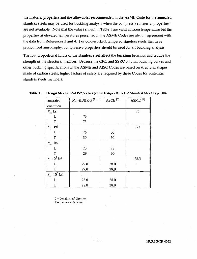
the material properties and the allowables recommended in the ASME Code for the annealed stainless steels may be used for buckling analysis when the compressive material properties are not available. Note that the values shown in Table 1 are valid at room temperature but the properties at elevated temperatures presented in the ASME Codes are also in agreement with the data from References 3 and 4. For cold-worked, tempered stainless steels that have pronounced anisotrophy, compressive properties should be used for all buckling analysis.
The low proportional limits of the stainless steel affect the buckling behavior and reduce the strength of the structural member. Because the CRC and SSRC column buckling curves and other buckling specifications in the ASME and AISC Codes are based on structural shapes made of carbon steels, higher factors of safety are required by these Codes for austenitic stainless steels members.
Table 1: Design Mechanical Properties (room temperature) of Stainless Steel Type 304
annealed condition
Mil-HDBK-5 [ 2 1 ] ASCE [ 3 ] ASME [41
Ftu ksi L T
73 75
75
F,v ksi L T
26 30
30 30
30
Fcy ksi L T
23 29
28 30
E 10 3ksi L T
29.0 29.0
28.0 28.0
28.3
Ec 103 ksi L T
28.0 28.0
28.0 28.0
L = Longitudinal direction T = transverse direction
- 1 1 - NUREG/CR-6322
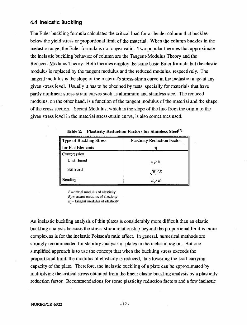
4.4 Inelastic Buckling
The Euler buckling formula calculates the critical load for a slender column that buckles below the yield stress or proportional limit of the material. When the column buckles in the inelastic range, the Euler formula is no longer valid. Two popular theories that approximate the inelastic buckling behavior of column are the Tangent-Modulus Theory and the Reduced-Modulus Theory. Both theories employ the same basic Euler formula but the elastic modulus is replaced by the tangent modulus and the reduced modulus, respectively. The tangent modulus is the slope of the material's stress-strain curve in the inelastic range at any given stress level. Usually it has to be obtained by tests, specially for materials that have partly nonlinear stress-strain curves such as aluminum and stainless steel. The reduced modulus, on the other hand, is a function of the tangent modulus of the material and the shape of the cross section. Secant Modulus, which is the slope of the line from the origin to the given stress level in the material stress-strain curve, is also sometimes used.
Table 2: Plasticity Reduction Factors for Stainless Steel [3]
Type of Buckling Stress for Flat Elements
Plasticity Reduction Factor
Compression Unstiffened
Stiffened
Bending
E/E
JE/E
E/E
E = initial modulus of elasticity Es = secant modulus of elasticity E, = tangent modulus of elasticity
An inelastic buckling analysis of thin plates is considerably more difficult than an elastic buckling analysis because the stress-strain relationship beyond the proportional limit is more complex as is for the inelastic Poisson's ratio effect. In general, numerical methods are strongly recommended for stability analysis of plates in the inelastic region. But one simplified approach is to use the concept that when the buckling stress exceeds the proportional limit, the modulus of elasticity is reduced, thus lowering the load-carrying capacity of the plate. Therefore, the inelastic buckling of a plate can be approximated by multiplying the critical stress obtained from the linear elastic buckling analysis by a plasticity reduction factor. Recommendations for some plasticity reduction factors and a few inelastic
NUREG/CR-6322 -12-

buckling charts for axially loaded and shear-loaded plates are presented in References 1 and 13. Table 2 shows the plasticity reduction factors for stainless steel suggested in the "Specification for the Design of Cold-Formed Stainless Steel Structural Members". [ 3 ] The plasticity reduction factors (T|) are formulated in terms of the initial modulus of elasticity (E), the secant modulus of elasticity (Es), and the tangent modulus (Et). The room temperature values of the secant modulus, the tangent modulus, and the plasticity reduction factors for austenitic stainless steel (Types 201,301, 304, and 316) are presented in both tables and charts in Reference 3. Alternatively, the values for Es, Et, and T| can be determined analytically using the Modified Ramberg-Osgood equation. These analytical expressions and the plasticity reduction factors at room temperature for stiffened and unstiffened elements taken from Reference 3 are presented in Appendix A. The plasticity reduction factors at higher temperature may also be determined from the Modified Ramberg-Osgood equation using the moduli at the proper temperature.
- 1 3 - NUREG/CR-6322

5.0 CLASSICAL BUCKLING FORMULAS FOR BASKET COMPONENTS
As discussed previously, the buckling analysis of an typical spent fuel basket consists of analyzing isolated members of the basket assemblies as idealized beam-columns and plates subjected to compressive end forces and moments. The idealized compression members of the basket assemblies are assumed to be prismatic along the length of the members and are supported only at the ends. Depending on the drop angle of the transportation cask, the applied loads acting on the members are assumed to be either axial, axial plus bending, biaxial, or biaxial plus lateral pressure. The cross section of the typical basket members are closed-sections and therefore will not buckle torsionally because of their large torsional rigidity. Similarly, lateral-torsional buckling, which is a form of instability combined by a sideway bending and twisting commonly associated with wide flange I beams or inadequately braced members with open-sections, is rarely an issue for the typical basket components. For these reasons, only the flexural buckling formulas for beam-columns and plates are presented below.
5.1 Column under axial loads t9] [11]
The Euler buckling load for a hinge-ended perfect column is defined as
rE = *f CD
As the Euler buckling load formula is invalid if the stress exceeds the proportional limit, it is more convenient to express it in terms of elastic buckling stress. By using the concept of effective length, Kl, to account for different end conditions of the column and the radius of gyration, r2 = I/A, the elastic buckling stress for a perfect column is defined as
and the inelastic buckling stress based on the tangent modulus theory is
K2E,
where E, is the tangent modulus of the material. Kl/r is the slenderness ratio of the column while the effective length, Kl, essentially is the length between the inflection points of the column. The theoretical and the recommended K values are shown in Figure 6.
NUREG/CR-6322 -14 -
Buckled shape of column is shown by dashed line
(a)
I (6) t t
A
I I I
I I
I 1 I I
u vh
4 Theoretical K value 0.5 0.7 1.0 1.0 2.0 2.0
Recommended K value when ideal conditions are approximated
0.65 0.80 12 1.0 2.10 2.0
End condition code 7 T
Rotation fixed. Translation fixed
Rotation free. Translation fixed
Rotation fixed, Translation free
Rotation free. Translation free
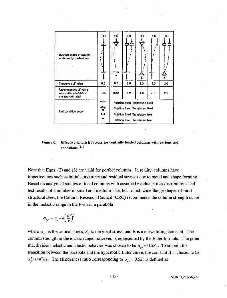
Figure 6. Effective-length K factors for centrally loaded columns with various end conditions I1 1!
Note that Eqns. (2) and (3) are valid for perfect columns. In reality, columns have imperfections such as initial curvatures and residual stresses due to metal and shape forming. Based on analytical studies of ideal columns with assumed residual stress distributions and test results of a number of small and medium-size, hot-rolled, wide flange shapes of mild structural steel, the Column Research Council (CRC) recommends the column strength curve in the inelastic range in the form of a parabola
a =S-B(«±)2
c r y \ r J
where acr is the critical stress, Sy is the yield stress, and B is a curve fitting constant. The column strength in the elastic range, however, is represented by the Euler formula. The point that divides inelastic and elastic behavior was chosen to be a = 0.55,,. To smooth the transition between the parabola and the hyperbolic Euler curve, the constant B is chosen to be S^/(4n2E) . The slenderness ratio corresponding to a c r = 0.5Sy is defined as
-15- NUREG/CR-6322

In summary, the CRC column curve (see Figure 13 on page 35) can be written Kl
for the inelastic case, — < C : r c
a = S cr y 2C2
(5)
Kl and for the elastic case, — > C : ' r c
5.2 Column under axial and bending loads [9][14][17]
A column under both axial and bending loads is known as a beam-column. Most of the members of a structural assembly are under combined axial and bending loads and therefore can be treated as beam-columns. An oblique drop of a transportation cask can result in this type of combined loadings on the basket members.
The behavior of beam-columns has been investigated extensively by many researchers. The analysis of beam-column is a complicated problem because of the many factors that affect the buckling modes of the member. These factors include the effect of the secondary moment due to axial load, complicated loadings of end moments and transverse loads on the member, and consideration of the moment capacity of the cross section in terms of lateral buckling. The methods available for the analysis of beam-columns, especially for those under complex loadings or for tracing inelastic behaviors of the beam-column, are usually involved with numerical techniques that are too laborious for routine design purpose. A simplified method suitable for practical design use, yet comprehensive enough to include the influence of the factors mentioned above, is the interaction equations that relate a safe combination of axial force and bending moments in the beam-column. Interaction equations are normally developed based on curve-fitting to existing analytical and experimental data on isolated beam-columns. Both ASME and AISC Codes use the interaction equations approach as part of the design specifications for members subjected to combined axial compression and bending loads.
There are two basic design approaches in the design of beam-columns. One is based on plastic design principles and the other is based on allowable stress criteria. The general form
NUREG/CR-6322 -16-

of the interaction equation based on the plastic design principles is
P CM JL + 2 < i (7) Pcr U-(P/Pe)]Mp
K }
where P = applied axial load p = buckling strength of the column in the absence of applied moments
P = — = elastic critical load for buckling in the plane of applied moment
M = maximum applied moment, excluding contribution from axial load interacting with deflection M = maximum bending moment capacity in the absence of axial load
Cm = moment reduction factor as a function of end moments.
In essence, P„ = GcrA, can be obtained by either Eqn. (5) or (6). If the column is a gradual yielding metal, then P„ =n2EtA/ (Kl/r)2 should be used. When lateral buckling is prevented by adequate bracing, Mp = ZSy is the plastic moment, where Z is the plastic section modulus of the structural member. Because Eqn. (7) assumes that the maximum moment is at or near the mid-length of the span, a coefficient (Cm), applied to the maximum moment, M, is needed to account for other cases where a beam-column is subjected to unequal end moments, to end moments that create reverse curvature, or to transverse loadings. The specific values of Cm are presented in Section 6 on page 28.
When the maximum moment occurs at the ends, it should be noted that the beam-column may fail due to the formation of a plastic hinge. In this case, the beam-column is limited by strength rather than by instability. Based on analytical results of wide flange sections, the following second interaction equation is developed for a beam-column having the maximum moment at the ends.
— + T T ^ - ^ 1 M<M (8) Py l-18A/p P
Py is defined as the axial yield load of cross section (SyA), and Mp is the plastic moment.
The interaction equation based on the allowable stress criteria can be developed from Eqn. (7) by replacing the plastic moment, Mp with the yielding moment, My= SyS where S is the section modulus of the cross section:
C M + 2 < 1 (9)
P [ l - ( P / P ) ] M v
P . ~m-
-17- NUREG/CR-6322

Similarly, Eqn. (8) can be rewritten as
£ + £*! (10)
5.3 Plate under uniaxial loads
The theoretical buckling stress for a plate of dimension a by b by thickness h, with uniaxial compressive load acting on sides x = 0 and x = a (Figure 7) is
nzE fh\2 ' e "c\2(l-v2)ybJ
n2D ~cb2h
(ID
where k = plate buckling coefficient, a function of plate dimension and buckle half waves, D = plate cross section rigidity, £7i3/[12(l-i)2)]
Nv
i iV
b > . V < > > >
- >
t ^ a »
V
V
V
V
> >
•\ ' < <
1 > .
Nv
a X
Figure 7. Thin plate (axbxh) subjected to uniformly distributed loads along edges x = 0 and x = a
The plate buckling coefficient, kc, is a function of the boundary conditions of the plate, the ratio a/b, and the number of half waves in the buckled shape. Figure 8 shows the plate buckling coefficient, kc, as a function of a/b ratio for 10 different ideal edge support conditions. The solid lines and the dashed lines represent, respectively, simple supports and fixed supports along the loaded edges. Fixing the loaded edges increases kc for small a/b values but as a/b increases the effects of the rotational restraint along the loaded edges becomes insignificant. When a/b is greater than four the clamped plate would buckle at virtually the same compressive load as a plate with simply supported load edges. Typically the basket components are long plates with a/b » 1 and in those cases, kc depends primarily on the type of support along the unloaded edges.
NUREG/CR-6322 - 1 8 -
16
14
12
10
\ -V-
l \ \
II v
X free
i , free t
V \ — — — — Loaded edges clamped \ ' •
v Loaded edges simply supported
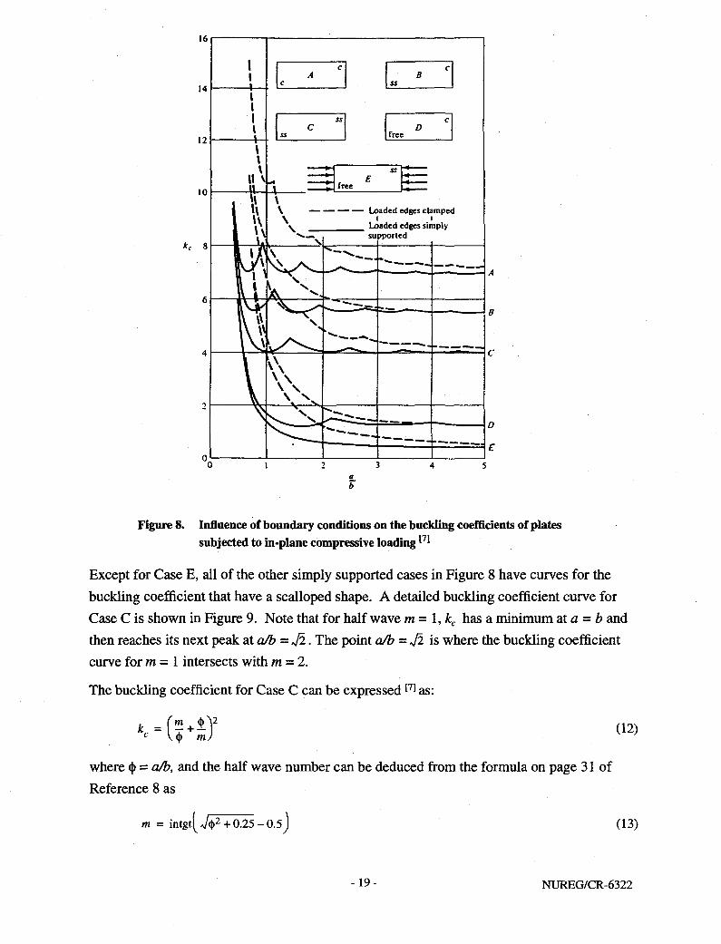
Figure 8. Influence of boundary conditions on the buckling coefficients of plates subjected to in-plane compressive loading ^
Except for Case E, all of the other simply supported cases in Figure 8 have curves for the buckling coefficient that have a scalloped shape. A detailed buckling coefficient curve for Case C is shown in Figure 9. Note that for half wave m = l,kc has a minimum at a = b and then reaches its next peak at a/b = Jl. The point a/b =Jlis where the buckling coefficient curve for m = 1 intersects with m = 2.
The buckling coefficient for Case C can be expressed[7] as:
where <{> = a/b, and the half wave number can be deduced from the formula on page 31 of Reference 8 as
m = intgt[V<|>2 + 0.25-0.5j (13)
-19- NUREG/CR-6322

Figure 9. Buckling coefficient curves for thin plates with all edges simply supported [20]
where the function intgt denotes the next integer greater than the value being evaluated.
The buckling coefficients for the other four boundary cases (Cases A, B, D, E) with the loaded edges simply supported for m = 1 can be approximated [8 ] by
The coefficients, C„ C2, and C3 are given in Table 3.
From differentiation of Eqn. (14) the value of the side ratio, <)>*, at which the buckling coefficient is a minimum, is given by the equation
(14)
( ( > * = ' c i Y / 4
(15)
and the corresponding minimum buckling coefficient,^*, is
2C, k * = , + C,
=n2 3 (16)
Therefore, if the side ratio is below the value (j)*, the buckling coefficient should be computed as given in Eqn. (14). On the other hand, if the side ratio is greater than or equal to (j)*, the buckling coefficient given by Eqn. (16) should be used. Note that for Case E, <|>* is undefined so Eqn. (14) should always be used to obtain the buckling coefficient.
NUREG/CR-6322 - 20 -

It is clear from Figure 8 that as the side ratio <|> and the half wave number m gets larger, the buckling coefficient for each edge boundary case approaches a limit. These limits are shown in Table 3 as the minimum buckling coefficient it *.
As discussed earlier, plasticity reduction factors can be applied to the plate buckling formula to approximate the inelastic buckling stress of a thin plate. Some of the inelastic buckling theories and their assumptions about plasticity reduction factors, inelastic Poisson's ratio and nondimensional buckling charts derived for axially compressed flanges and plates are presented in Reference 13. However, the evaluation of plasticity reduction factors is more involved because they are a function of secant modulus, tangent modulus, and inelastic Poisson's ratio. A simpler formulation for the inelastic buckling of thin plates that compares closely with experimental data based on simply supported plates is
a - k cr c
r\n2E „ 1 2 ( l - \ ) 2 ) (b/h)2. or, (17)
a " c b2h (18)
where r| = plasticity reduction factor = /—.
As for various types of stainless steel, tables and charts of tangent moduli and plasticity reduction factors are available in Reference 3 and in Appendix A.
Table 3: Values of coefficients Cj , Ci, C3, <)>*, and kc* for axially loaded thin plate with loaded edges simply supported (v = 0.3) and m = 1 [ 8 ]
Boundary Conditions of unloaded edges Q c2 c 3 < | > * J fc c *
Clamped, Clamped (Case A) 1.0 5.29 2.37 0.66 6.97
Clamped, Simply Supported (Case B) 1.0 2.50 2.25 0.80 5.42
Clamped, Free (Case D) 1.0 0.139 0.505 1.64 1.25
Simply Supported, Free (Case E) 1.0 0.0 0.390 — 0.425
Simply Supported, Simply Supported (Case C) — — — 1.00 4.0
A particular boundary condition that is not addressed by the boundary cases in Figure 8 is a plate with two free unloaded edges. A plate with this type of boundary condition is known as "wide column" because its theoretical buckling stress is analogous to the Euler column formula. Substituting the plate bending stiffness D, the Euler formula can be rewritten for a
- 2 1 - NUREG/CR-6322
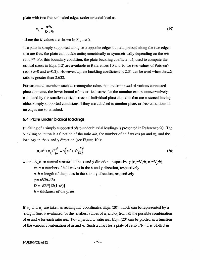
plate with two free unloaded edges under uniaxial load as
°- = MH ( 1 9 )
where the K values are shown in Figure 6.
If a plate is simply supported along two opposite edges but compressed along the two edges that are free, the plate can buckle antisymmetrically or symmetrically depending on the a/b ratio. [ 20 ] For this boundary condition, the plate buckling coefficient kc used to compute the critical stress in Eqn. (12) are available in References 10 and 20 for two values of Poisson's ratio (D=0 and D=0.3) . However, a plate buckling coefficient of 2.31 can be used when the a/b ratio is greater than 2.632.
For structural members such as rectangular tubes that are composed of various connected plate elements, the lower bound of the critical stress for the member can be conservatively estimated by the smallest critical stress of individual plate elements that are assumed having either simply supported conditions if they are attached to another plate, or free conditions if no edges are so attached.
5.4 Plate under biaxial loadings
Buckling of a simply supported plate under biaxial loadings is presented in Reference 20. The buckling equation is a function of the ratio alb, the number of half waves (m and n), and the loadings in the x and y direction (see Figure 10 ):
axm2 + C S y n 2 T 2 = \ m 2 + n2l2j ( 2°)
where c„ay = normal stresses in the x and y direction, respectively (a^N/h, Gy=Ny/h) m,n = number of half waves in the x and y direction, respectively a, b = length of the plates in the x and y direction, respectively Y=n2D/(a2h) D= EhV[12(l-v>2)] h = thickness of the plate
If a and a v are taken as rectangular coordinates, Eqn. (20), which can be represented by a straight line, is evaluated for the smallest values of a^and a y from all the possible combination of m and n for each ratio alb. For a particular ratio alb, Eqn. (20) can be plotted as a function of the various combination of m and n. Such a chart for a plate of ratio alb = 1 is plotted in
NUREG/CR-6322 - 22 -

M
Ny
>> >f \r v >' >' >' V if >' >' >'
: ii
> < > <
» * a >< > <
a
O A A A A A A A A A A A A C I A
A/„
Figure 10. Thin plate subjected to uniformly distributed loads along all edges
Reference 20 and it is shown here as Figure 11. The values of m and n are indicated on the lines and positive values of cx and <5y indicate compressive stresses. The lowest values of ax
and a yare represented by the solid line formed by points ABCD. For any value of ax the critical value of ay is the ordinate of a point on the polygon ABCD that has Gx as the abscissa. The intersection point of the line BC with the abscissa is the critical stress ax when <5y = 0, that is the case a simply supported square plate subjected to uniaxial load in the x direction. The critical stress for cy = 0 is A%2DI(a2h), which is identical to the value obtained from Eqn. (11) with a = b. If Gx= Gy, the critical stress for the plate is the intersection of a 45 degree line drawn through the origin with the line BC. This critical stress for a square plate under equal biaxial load is 2ji2D/(a2h), which is half of the critical stress for the same square plate under uniaxial load.
As an example, the critical stress envelope analogous to Figure 11 is shown in Figure 12 for a simply supported plate with a ratio alb =15. Because compressive loads are the main interest, only the first quadrant is shown. The lowest values of o^and ay are represented by the polygon formed by the points ABCDEF. Note that a similar chart needs to be prepared for each alb ratio. Though the evaluation of Eqn. (20) is simple, the calculation is repetitious and therefore is best performed by a computer program. In practice, the a/b ratio of the plate is known. So, partly because of simplicity, and partly because of accounting for plates with other boundary conditions other than simply supported plates, the critical stresses of a xand a y
can be represented conservatively by a line connecting points A and F. For any given ratio alb, points A and F can be computed by Eqn. (20). Point A is the critical stress associated with half wave numbers m = n= 1. Because a long plate buckles in such a pattern that its buckled length approaches the width of the plate, Point F is the critical stress associated with
-23- NUREG/CR-6322

\ J ' i , \
N \ \ -1 Division = 2 ^ ° < ^ \
-1 Division = 2 ^ °
' " • ' " • ' • " j o —\ -V \
I t
s \ , 22 \ r — .
A" R^ ^12 \
i N _ A" • — - \ K
SJI \ 1 k
n \ | \ \ ^
VJ \ \31 \ \
\ \ \ 2P
i \
K \
Figure 11. Critical stress envelope for a simply supported plate of alb = 1 under biaxial loading
1000
800
KI « 600 -
400
200
1 — r • • - 1 - | 1 1 1 I \ ' i - i — | i i - i — | — i i i
- -\ . \ m=20, n=l Ns, \ \ NS/ \ \
\ \ \ \ \
'""•• ^ v N
\ \
~" ^ s. \ "* ^ N. \ "•• «* "•••.. \ . \
** .̂ N \ \ • m=5,n=i «. '"'•••. \ \ ~ - — _ „ _ * • " ^ "•-•-. N . \
- / \ m=l, n=l B c^r^ST""-A;;------" - D H : ^ \ •
i i i 1 i . i i . 1 1 I 1 1 1 1 1 N i . . , X
200 400 600 800 "j_ 1000
Figure 12. Critical stress envelope for a plate of alb = 15 under biaxial loading
NUREG/CR-6322 -24-
the longitudinal half wave number m = alb and n = 1.
Based on the discussion above, a simple interaction expression can be formulated for square plates, or for long plates that buckle in square waves as
a a - £ + - ? = 1.0 (21) °cx °cy
where cx = stresses in the x-direction ay = stresses in the y-direction a„ = critical buckling stress of the plate when it is loaded uniaxially in the x-direction o^ = critical buckling stress of the plate when it is loaded uniaxially in the y-direction
The critical stresses Gcx and a^,, can be computed either by Eqn. (20) or by using the formulas for uniaxial loadings given in Eqn. (11) and Eqn. (19).
5.5 Plate under biaxial loads and lateral pressure
Explicit formulas or interaction equations for plates under this type of loadings are scarce and experimental data are very limited as well. Reference 15 notes that the Norwegian DnV-OS (1982) design code has a recommendation for load combinations that include lateral pressure. However, it is limited to those cases where the in-plane loads are small and the collapse is primarily due to lateral pressures. Interaction equations proposed in most studies on this topic are numerically based and need to be verified with more extensive experimental results. Therefore, other methods such as finite element methods or experimental testing, rather than classical methods, are recommended to analyze this type of complex loading. In some cases, the plate under biaxial loads and lateral pressure may be approximated by treating the plate as a beam-column subjected to a transverse line load.
- 2 5 - NUREG/CR-6322

6.0 BUCKLING ACCEPTANCE CRITERIA FOR SPENT FUEL BASKET COMPONENTS
Following the guidelines in NRC Regulatory Guide 7.6 [ 2 2 ] , Regulatory Guide 7.11 [ 2 3 ] , spent fuel transportation casks may adopt the requirements in the ASME Boiler and Pressure Vessel Code, Section III, Level A Service Limits as the design criteria for the normal loading conditions. Similarly, the design criteria for the hypothetical accident conditions may adopt the requirements for Level D Service Limits in the ASME Code. Using the same philosophy, the buckling design criteria of the spent fuel basket components may adopt these same guidelines, and specifically follow the rules in Subsection NF — Component Supports, in Section III of the ASME Code for Level A limits, and the rules in Appendix F for Level D limits.
6.1 ASME Section III, Subsection NF (Component Supports)
Subsection NF classifies component supports into three groups of support: Plate- and Shell-Type Supports, Linear-Type Supports, and Standard Supports. As implied by its name, Plate- and Shell-Type Supports are those supports of plate and shell construction. Linear-Type Supports are those that are generally made of structural shapes and built-up members. Standard Supports are usually items that are readily available commercially, like pipe hangers and snubbers. As discussed previously, typical spent fuel basket assemblies can be idealized as beams and plates, so the design criteria for the Linear-Type and Plate- and Shell-Type supports are presented here.
In general, Subsection NF offers multiple design criteria and alternative analysis procedures. It allows for design strictly by analysis: using either elastic or limit analysis, by experimental stress analysis, or by load rating. The design criteria chosen for this study are based on the elastic design-by-analysis approach, because in part it is the simplest and is conservative for the typical basket components considered here, and in part because it conforms to the general design philosophy of the Regulatory Guides mentioned earlier. Note that even though the true failure stresses for a thin plate may be much higher than the calculated critical buckling stresses, the postbuckling strength of a thin plate should not be relied upon because the deformation requirements on the baskets may govern the design.
The design criteria presented in the following sections are those solely related to buckling, that is, loads which are compressive in nature. Other design requirements on tension, bending, shear, weld stresses, and fatigue, etc., must also be met for a complete component support design.
NUREG/CR-6322 - 2 6 -

6.2 Linear-Type Supports for Normal Conditions of Transport
6.21 Axial Compression (NF-3322.1 (c)) The allowable stresses, Fa, for a Linear-Type Support under compression loads should satisfy the following requirements:
(1) Steel columns, except those fabricated from austenitic stainless steel, that have met the Width Ratio requirements (see Section 6.23 on page 29):
for inelastic buckling,
Fa = )-m.
5 3 Kl \f Kl y 3 + 8rC %\rC
i f - < C . = /27C2#,or (22)
for elastic buckling,
F_ = 12 n2E
a 23 (Kl/r)2 if->C (23)
Note that Cc is the slenderness ratio that separates elastic buckling from inelastic buckling (See page 16). Essentially Eqn. (22) is the inelastic buckling Euler formula with the factors of
safety of 1 5 3 Kl 1 f Kl N3 3 + 8rC„ s{rCr
included. On the other hand, Eqn. (23), with a factor of safety of
12/23, applies to elastic buckling of columns.
(2) Columns fabricated from austenitic stainless steel that have met the Width Ratios requirements (see Section 6.23 on page 29):
for inelastic buckling,
F = S I 0.47 - ^i£l a y\ 444
for elastic buckling,
F = s | 0.40 - K^-a yy 6oo
if — < 120, or r
if —> 120 r
(24)
(25)
6.22 Combined Axial Compression and Bending (NF3322.1 (e)) For members subjected to both axial and bending loads, stresses shall be proportioned to satisfy the requirements of Eqns. (26), (27), and (28):
- 27 - NUREG/CR-6322
F ' V ex J F i ,
ey J %
fa + 4 £ + 4)L< 1 0 ( 2 7 )
° - 6 0 5
y r b x
F
h
Eqn. (28) may be used in lieu of Eqns. (26) and (27):
£ + ^ U ^ < 1 . 0 if £ £0.15 (28) ra rbx rby ra
and,
F ' = except for austenitic steel (29) « 1.92 (Klb/rb)2
n2E F ' = for austenitic steel (30) e 2A5(Klb/rb)2
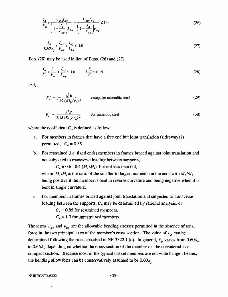
where the coefficient Cm is defined as follow:
a. For members in frames that have a free end but joint translation (sidesway) is permitted, Cm = 0.85.
b. For restrained (i.e. fixed ends) members in frames braced against joint translation and not subjected to transverse loading between supports,
Cm = 0.6 - 0.4 (M,IM2) but not less than 0.4, where M,/M2is the ratio of the smaller to larger moments on the ends with M,/M2
being positive if the member is bent in reverse curvature and being negative when it is bent in single curvature.
c. For members in frames braced against joint translation and subjected to transverse loading between the supports, Cm may be determined by rational analysis, or
Cm = 0.85 for restrained members, Cm = 1.0 for unrestrained members.
The terms Fbx and F. are the allowable bending stresses permitted in the absence of axial force in the two principal axes of the member's cross section. The value of Fb can be determined following the rules specified in NF-3322.1 (d). In general, Fb varies from 0.605 to 0.66s depending on whether the cross-section of the member can be considered as a compact section. Because most of the typical basket members are not wide flange I beams, the bending allowables can be conservatively assumed to be 0.60s .
NUREG/CR-6322 -28-

The "Design by Linear Elastic Analysis" approach in Subsection NF does not provide any acceptance criteria for combined axial compression and bending in the inelastic range. But in the "Limit Analysis Design" approach, interaction equations for combined axial compression and bending are specified. The basic assumption in Limit Analysis is that the loaded members are stressed beyond the yield stress and have undergone inelastic deformations. Although the basis for the two approaches are completely different, the interaction equations given in these two design methods are essentially the same (see Section 5.2 on page 16). It is proposed to adopt the acceptance criteria provided in the "Limit Analysis Design" for members which, under combined axial load and bending moment, have stresses beyond the yield limit of the material.
The proposed criteria for members which have deformed inelasically due to both axial load and bending moment shall satisfy the following interaction equations: (NF-3342.2)
P . -m-C
m
M
+ <1 (31)
F + L W ^ 1 0 ; M*MP ( 3 2 )
y P
where
Pe = l.92AFe' where Fg' is taken either from Eqn. (29) or Eqn. (30)
Pcr = 1.7AFa where Fa is defined by Eqns. (22) through (25), and
for columns braced in the weak direction: M = M = S Z , while m p y x '
for columns unbraced in the weak direction: M = M tn p
1.07 - ' ^ l l l 3160 J <M P
6.23 Width Ratios (NF3322.2 (d)) Members that are subjected to axial compression or compression due to bending are considered to be fully effective if the width-thickness ratio, b/t, is not greater than the values shown in Table 4. If the b/t ratio exceeds the requirement in Table 4, the member is considered to be "slender compression member", the allowable stress of axially loaded compression members are to be modified with reduction factors according to Section NF-3322.2(e) of the ASME Code.
- 29 - NUREG/CR-6322

Table 4: Width Ratios Requirements
Description of elements Limiting Width-Thickness ratios *
Unstiffened elements (i.e. simply supported along one edge), such as legs of single-angle struts and legs of double angle struts with separators N y
Unstiffened elements such as struts comprising double angle in contact; angles or plates projecting from girders, columns; compression flanges of beams; and stiffeners on plate girders
< ^ 1 V y
Stems of Tees < 127
4 y
Stiffened elements, (i.e.laterally supported along both edges), such as flanges of square and rectangular box sections of uniform thickness
, ,238
Stiffened elements such as unsupported width of cover plates perforated with holes
< 317
V y
All other uniformly compressed stiffened elements , ,253
V y
* Sy is in ksi unit
6.3 Linear-Type Supports for Hypothetical Accident Conditions
6.31 Axial Compression (Appendix F-1334.3)
Maximum load in axially loaded compression members is limited to either (a) or (b) below:
(a) Two-thirds of the buckling load determined either by comprehensive stability analysis which included large deformation and initial imperfection, or by full-scale prototype testing.
(b) the maximum allowable load for ferritic steels which have initial out-of-straightness less than 1/1000 of the unsupported length is determined as follow:
(1) For 0<A,<1
L = 1 ,y
Py 1.11+0.50*.+ 0.17 A- 2-0.28 A,3
For \<X<j2
NUREG/CR-6322 -30-

For A.>72
— = — (35) Py 3X2 K }
where P = maximum allowable load, lbs Py=SyAg, lbs A = Area of gross section, in.2
% nV r )*JE
(2) For nonstress-relieved heavy structural shapes (web and flange thickness greater than 1 in.) or for nonstress-relieved built-up members using universal mill plate, the following rules apply:
ForO<A,< 1
P 1 X2
4 py = 1.11 + 0.75X + 0.83X2--0.8 IX 3
For l < X < ;J2
P py =
^ 4 2 ) FoTk>j2
P i Py = 1.88X2
(36)
(37)
(38)
Notice that unlike the previous Subsection NF-3322.1 (c), no criteria specified for austenitic stainless steel member are given in this Subsection F-1334.3. However, assuming that the same factors of safety ratio between the carbon steel and austenitic stainless steel in NF-3322.1 (c) can be applied to F-1334.3, the design criteria for axially compressed austenitic stainless steel member can be determined. For clarity, let's denote the design criteria given in NF-3322.1 (c) as "Level A" criteria and those given in F-1334.3 as "Level D" criteria. Then the austenitic stainless steel criteria for the hypothetical accident conditions can be expressed
-31- NUREG/CR-6322

as
5 5 Level D = [ CSJu^X A X C 5 ^ v e l D ( 3 9 )
where SS and CS stand for stainless steel and carbon steel, respectively. Such a design curve is shown as "Level D - SS" in Figure 13 on page 35.
Writing the expression in terms of Equation numbers, the allowables for the austenitic stainless steel are proposed as
^Level D = [Eqns (43), (44)] x [Eqns (33), (34), (35)] + [Eqns (41), (42)] (40)
6.32 Combined Axial Compression and Bending (Appendix F-1334.5) Members subjected to combined axial compression and bending shall satisfy Eqns. (26), (27), and (28) above with allowable stresses defined as follows:
(a) Fa = P/A where P is determined by the appropriate Eqns. (33) to (35)
( b ) F ; = ^ — -e 1 . 3 0 ( ^ / ^ ) 2
(c) F 6 is determined by (l)or (2) below:
(1) Fb=fSy if the member qualifies as a compact section under criteria of NF-3322.1(d)(1) where/is the plastic shape factor for the cross section. Note that NF-3322.1(d)(1) is not repeated in this report and details can be found in the ASMEB&PVCode.
(2) If the member does not qualify as a compact section, Fk is determined from the allowables given in NF-3322.1(d)(2) increased by a factor of 1.11 (to maintain a nominal factor of safety of 1.5 against instability). Note that NF-3322.1(d)(2) is not repeated in this report and details can be found in the ASME B&VP Code.
The allowables for the members of austenitic stainless steel are adjusted according to the ratio between the factors of safety for the carbon steel and stainless steel as indicated in Eqn. (39). The proposed acceptance criteria for the austenitic stainless steel members shall follow the same requirements shown in (a), (b), (c) above with the following modifications in
(a) Fa = P/A where P is determined by the appropriate Eqn. (40), and in
lt2E . . 1 (•FS„A
(Klb/rb)* FS CS . . , „ „ , _ 1.92. (b)F ' = — . x-^- , where FS = -—^ x (F5 r ? ) , l r > = ^ | x 1.30 = 1.46
W « (Kl./r.)2 FS FSCC ¥ _ _ 1 A CS'LevelD 2.15 V" "SSJ Level A
NUREG/CR-6322 - 3 2 -

For the acceptance criteria for members deformed irielastically, the "Limit Analysis Design" approach is proposed again as it was in Section 6.22 on page 29. The values for Fg' and Fa in Eqns. (31) and (32) need to be modified using the allowables given in this section for the appropriate materials.
6.4 Plate- and Shell-Type Support for Normal Conditions of Transport
The design rules for Plate- and Shell-Type Supports are described in NF-3200 of the ASME B&VP Code. No detailed design rules regarding axial loads and combined axial and bending loads in the elastic design-by-analysis approach are given in Subsection NF. Stress limit factors for Class 1 Plate- and Shell-Type component supports are shown in Table NF-3522(b)-l. As shown in Table NF-3522(b)-l, the computed stresses for Service Level A should be less than or equal to 1/2 of the critical buckling stress. However, no specifics are provided for the analysis method to evaluate the critical buckling stress for plate- and shell-type supports. Therefore, it is proposed that the buckling formulas for the plates presented in Section 5 be used to evaluate the theoretical critical stress for plate-type supports. The design allowable then is 1/2 of the computed theoretical buckling stress. For shell-type supports, the methodology and criteria in NUREG/CR-4554, "SCANS: Volume 6, Theory Manual, Buckling of Circular Cylindrical Shells" [25\ may be used.
6.5 Plate- and Shell-Type Support for Hypothetical Accident Conditions
As indicated in Table NF-3522(b)-l, Service Level D follows the rules in Appendix F. However, as in the case of Level A Service Limit design, no detailed design rules for Plate-and Shell-Type supports are provided in Appendix F. The only requirement for compressive stresses (F-1332.5) is that it be limited to two-thirds of the value of buckling load determined either by comprehensive analysis which includes initial imperfections and residual stresses, or by tests. It is proposed again that the buckling formulas for plates presented in Section 5 be used to evaluate the theoretical critical stress for plate-type supports. The design allowable then is 2/3 of the computed theoretical buckling stress. NUREG/CR-4554, "SCANS: Volume 6, Theory Manual, Buckling of Circular Cylindrical Shells" [ 2 5 ], may be used.
6.6 Factors of Safety
The factors of safety are used to account for geometrical imperfections, residual stresses, load eccentricity and uncertainties related to the magnitude of the applied loads which are unavoidably encountered in the analysis of a real structure. The acceptance criteria from the ASME Code presented in the earlier sections utilized different factors of safety for different levels of service (Level A and Level D), for different types of materials (carbon steel and
- 33 - NUREG/CR-6322

austenitic stainless steel), and for different types of load combinations. Knowing the factors of safety used in the design translates into a better understanding of the margins of safety reserved in the structure. The factors of safety used in the acceptance criteria for the linear-type supports under service level A (the normal conditions of transport) and service level D (hypothetical accident conditions) are presented below.
6.61 Service Level A - axial compression
ft" Kl f~S~~ If X is defined as M = — \-2- , the CRC column curve represented by Eqns. (5) and (6) can
be rewritten for the inelastic case, X<j2:
and for the elastic case, X>Jl, (i.e. Euler buckling curve):
?r = \ (42) Py X2
where P = maximum allowable load, lbs Py = SyA , lbs
A = Area of gross section, in 2
Similarly, acceptance criteria in the ASME Code for axial compression member can also be written in terms of X so that for the inelastic case, X<j2:
L = * - * 2 / 4 (43) p
y 5 ¥ M _ i a y
and for the elastic case, X > Jl :
L - 1 Py ~ 1.92 (A.2)
(44)
The two equations above and the Level D design curves, the theoretical Euler buckling curve, and the CRC column curve are plotted in Figure 13. Comparing Eqns. (41), (42), (43), and (44), the factors of safety for inelastic buckling varies from 1.62 to 1.92 and the factor of safety is a constant 1.92 in the elastic range. Graphically, the factors of safety embedded in the "Service Level A - carbon steel" criteria is just the ratio between the "CRC Curve" and the "Level A - CS" curve shown in Figure 13. The four curves representing the factors of safety for the ASME design criteria for axially compressed members are plotted in Figure 14.
NUREG/CR-6322 -34-

1.2 I 1 1 1 1 1 1 r
IJO
PyOA
0£
i^y»
OA -
0.2
OX)
-I 1 r -i 1 r
CRC Curve
••••.:oi
Euler Curve
"""*-^ ^ e M -^ - c s
Level D - SS / Level A - SS
I I I
0.0 0.4 0 3 1.2 14 2.0
x- p: = L/pL
Figure 13. CRC column curves and ASME design curves
CRC Curve: Eqns. (41) & (42) Level A - CS: Eqns. (43) & (44) Level A - SS: Eqns. (45) & (46) Level D - CS: Eqns. (33), (34), & (35) Level D - SS: Eqn. (40)
The curve labeled as "Level A -SS" in Figures 13 and 14 corresponds to the design criteria for the austenitic stainless steel members. In order to plot them as a function of X, Eqns. (24) and
y = 10.47-y
Kl r
120X
(25) assume that cc = — = 120. In this case, the criteria can be expressed as
V AAAjlj
r^OAO-™^) if (X>J2) Py \ 6O0j2J
(45)
(46)
and the factors of safety vary from 2.11 to 2.69. Note that if another value of Cc is assumed, the factors of safety will be different from those shown in Figure 14.
6.62 Service Level D - axial compression The Service Level D design curves for axially loaded carbon steel members and austenitic stainless steel are labeled respectively as "Level D - CS" and "Level D - SS" in Figure 13.
- 3 5 - NUREG/CR-6322

The corresponding factors of safety curves are shown in Figure 14. The factors of safety for carbon steel range from 1.10 to 1.50, while the factors of safety for stainless steel vary from 1.41 to 2.12.
3.0 I 1 1 1 1 1 1 1 1 1 1 1 1 1 1 1 ] 1 1 r
2.5
'S DO
2.0
1.5 - ..•
\P N6\ { .s*
\fi .*& iS> .&
Level A-CS
Level D - CS
| j 0 I 1 I I ' I I I I I I I ' I I 1 I I I L .
0.0 0.4 0.8 1.2 ^£ 2.0
4G, r HtPE
Figure 14. Factors of safety for axially compressed members embedded in the ASME Code
NUREG/CR-6322 - 3 6 -
7.0 SUMMARY
The buckling analysis methods presented in this report utilize many classical buckling formulas for columns and plates with different types of loadings. The analysis approach taken here is based on the current design practice where the entire structure is frequently designed by sizing the individual members of the assemblies. Adopting the same philosophy, the spent fuel baskets of a shipping cask can be analyzed by evaluating the performance of their individual structural members. Furthermore, the structural components in a typical basket are generally plates and tubular members, of which many buckling formulas are available in the literature. These classical formulas also serve partially as the basis for the buckling acceptance criteria in the AISC and ASME B&PV Codes.
As in many other NUREGs, the acceptance criteria from the ASME B&PV Code are used to determine the adequacy of the basket components. Specifically, the criteria specified in Division I, Section III, Subsection NF are used for the Normal Conditions of Transport. Provisions given in Section III, Appendix F are adopted for the Hypothetical Accident Conditions. In some instances, new criteria are proposed when the Code does not give any specifications related to certain conditions pertaining to basket components. A few suggested allowables are proposed for austenitic stainless steel members.
Basket components frequently use austenitic stainless steel because of its fracture toughness. Because of the low proportional limits and the nonlinear stress-strain relationship of austenitic stainless steel, plasticity reduction factors are used in the buckling formulas to safeguard against premature buckling. Tables of plasticity reduction factors are included in the report for quick reference. However, because data related to the buckling performance of stainless steel are limited, further study in this area is needed.
This report does not discuss how to determine the applied loads for the basket assemblies. It is assumed that the loads have been determined from other system analyses and have been combined with the appropriate thermal load, pressure, free-end constraint, and impact loads to form the worst load combination. Proper load combination must be used in the buckling analysis of the basket.
- 37 - NUREG/CR-6322


8.0 REFERENCES
1. Allen, H. G. and Bulson, P. S., Background to Buckling, McGraw-Hill, Great Britain, 1980.
2. American Institute of Steel Construction, Manual of Steel Construction, Allowable Stress Design, Ninth Edition, AISC, Chicago, IL, 1989.
3. American Society of Civil Engineers, Specification for the Design of Cold-Formed Stainless Steel Structural Members, ASCE, New York, NY, 1991.
4. American Society of Mechanical Engineers, ASME Boiler and Pressure Vessel Code, United Engineering Center, New York, NY, 1992.
5. Bazant, Zdenek P. and Cedolin L., Stability of Structures, Elastic, Inelastic, Fracture, and Damage Theories, Oxford University Press, New York, NY, 1991.
6. Brockenbrough, R. L. and Johnston, B. G., Steel Design Manual, United States Steel Corp., Pittsburgh, PA, 1981.
7. Brush, Don O. and Almroth, Bo O., Buckling of Bars, Plates, and Shells, McGraw-Hill, St. Louis, MO, 1975.
8. Bulson, P.S., The Stability of Flat Plates, American Elsevier, New York, NY, 1969.
9. Chen, W.F. and Lui, E.M., Stability Design of Steel Frames, CRC Press, Boca Raton, Florida, 1991.
10. Column Research Committee of Japan, Handbook of Structural Stability, Corona Publishing Company, Tokyo, 1971.
11. Galambos, T. V. (editor), Guide to Stability Design Criteria for Metal Structures, Fourth Edition, Structural Stability Research Council, Wiley-Interscience Publication, New York, NY, 1988.
12. Gaylord, E.H. Jr. and Gaylord, C. N., Design of Steel Structures, 2nd Edition, McGraw-Hill, NY, 1972.
13. Gerard, G., and Becker, H., Handbook of Structural Stability, Part I, Buckling of Flat Plates, NACA TN 3781, National Advisory Committee for Aeronautics, Washington, D.C.,1957.
14. Johnston, B. G. (editor), Guide to Stability Design Criteria for Metal Structures, Third Edition, Structural Stability Research Council, Wiley-Interscience Publication, New York, NY, 1976.
- 39 - NUREG/CR-6322

15. Kenny, J. P. and Partners Ltd., Buckling of Offshore Structures, Gulf Publishing Company, Houston, TX, 1984.
16. McGuire, William, Steel Structures, Prentice-Hall, Inc., Englewood Cliffs, N.J., 1968.
17. Narayanan, R. (editor), Beams and Beam Columns: Stability and Strength, Applied Science Publishers, Essex, England, 1983.
18. Office of the Federal Register, National Archives and Records Administration, Packaging and Transportation of Radioactive Materials, Code of Federal Regulations, Title 10, Part 71, Washington, DC, 1991.
19. Szilard, Rudolph, Theory and Analysis of Plates, Classical and Numerical Methods, Prentice-Hall, New Jersey, 1974.
20. Timoshenko, S. P. and Gere, J. M., Theory of Elastic Stability, Second Edition, McGraw-Hill, New York, 1961.
21. U. S. Department of Defense, Military Handbook, Metallic Materials and Elements For Aerospace Vehicle Structures, Volume 1, MJJL-HDBK-5F, 1990.
22. U. S. Nuclear Regulatory Commission, Regulatory Guide 7.6: Design Criteria for the Structural Analysis of Shipping Casks Containment Vessels, Revision 1, Washington, D.C., 1980.
23. U. S. Nuclear Regulatory Commission, Regulatory Guide 7.11: Fracture Toughness Criteria of Base Material for Ferritic Steel Shipping Cask Containment Vessels with a Maximum Wall Thickness of 4 Inches (0.1 m), Washington, D.C., 1991.
24. U. S. Nuclear Regulatory Commission, SCANS: Vol. 2, Theory Manual, Impact Analysis, NUREG/CR-4554 Vol. 2, 1986.
25. U. S. Nuclear Regulatory Commission, SCANS: Vol.6, Theory Manual, Buckling of Circular Cylindrical Shells, NUREG/CR-4554 Vol. 6, 1990.
26. Young, Warren C , Roark's Formulas for Stress and Strain, Sixth Edition, McGraw-Hill, St. Louis, MO, 1989.
27. Yu, W. W., Cold-Formed Steel Design, Second Edition, John Wiley & Sons, NY, 1991
NUREG/CR-6322 - 40 -
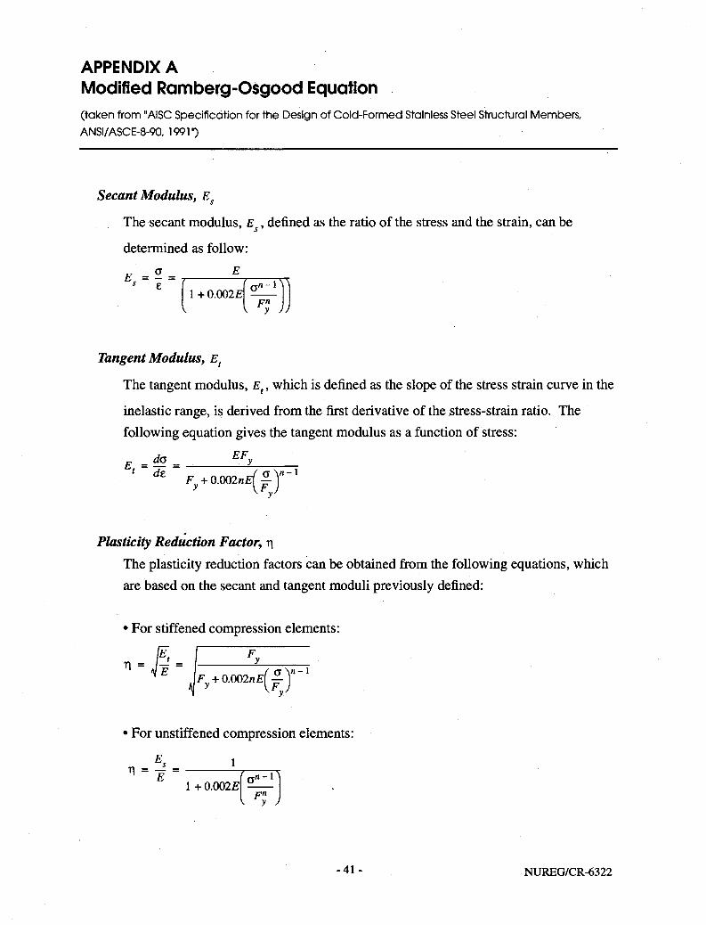
APPENDIX A Modified Romberg-Osgood Equation (taken from "AISC Specification for the Design of Cold-Formed Stainless Steel Structural Members, ANSI/ASCE-8-90, 1991")
Secant Modulus, Es
The secant modulus, E , defined as the ratio of the stress and the strain, can be
determined as follow:
E. = ° . 5
1 + 0.002£ q " - 1
Fn
v y J
Tangent Modulus, Et
The tangent modulus, Et, which is defined as the slope of the stress strain curve in the
inelastic range, is derived from the first derivative of the stress-strain ratio. The following equation gives the tangent modulus as a function of stress:
EF E. = ""
da - - y
' d £ VO.002^)"-1
Plasticity Reduction Factor, rj The plasticity reduction factors can be obtained from the following equations, which are based on the secant and tangent moduli previously defined:
• For stiffened compression elements:
Tl - lE' - 1 ^ "' *i E i f a V - i
• For unstiffened compression elements:
n - E° - l n E
1 + 0.002E
- 41 - NUREG/CR-6322

For buckling stress of columns and lateral buckling strength of beams:
1 1 = £ =
Fy + 0.002«£l o > - i (S In these equations:
CT = normal stress;
e = normal strain;
E = initial modulus of elasticity
F = 0.2% offset yield strength; and
n = coefficient, as given in Table Al.
Table Al: Coefficient n Used for Modified Ramberg-Osgood Equation
Types 201, 301, 304, 316
Types of Stress
Annealed & 1/16-
Hard 1/4 - Hard 1/2 - Hard
Type 409 Types 430 and 439
Longitudinal tension 8.31 4.58 4.21 10.77 8.43
Transverse tension 7.78 5.38 6.71 15.75 14.13
Transverse compression 8.63 4.76 4.54 15.76 14.3
Longitudinal compression 4.10 4.58 4.22 9.70 6.25
NUREG/CR-6322 - 4 2 -

Table A2: Plasticity Reduction Factors for Stiffened Elements (Types 201,301,304,316)
JE/E Longitudinal compression Transverse compression
Stress ksi Annealed and 1/16 Hard
1/4 Hard 1/2 Hard Annealed and 1/16 Hard
1/4 Hard 1/2 Hard
0 1.00 1.00 1.00 1.00 1.00 1.00 4 1.00 1.00 1.00 1.00 1.00 1.00 S 1.00 1.00 1.00 1.00 1.00 1.00 12 1.00 1.00 1.00 1.00 1.00 1.00 16 0.77 1.00 1.00 1.00 1.00 1.00 20 0.67 1.00 1.00 1.00 1.00 1.00 24 0.58 0.79 0.98 0.81 1.00 1.00 28 0.50 0.71 0.86 0.62 1.00 1.00
32 0.65 0.80 1.00 1.00 36 0.60 0.75 1.00 1.00 40 0.56 0.71 0.99 1.00 44 0.52 0.68 0.93 1.00 48 0.48 0.64 0.88 1.00 52 0.45 0.60 0.84 1.00 56 0.57 0.80 0.97 60 0.53 0.77 0.94 64 0.50 0.73 0.91 68 0.47 0.70 0.87
Table A3: Plasticity Reduction Factors for Unstiffened Elements (Types 201,301,304,316)
JE/E Longitudinal compression Transverse compression
Stress ksi Annealed and 1/16 Hard
1/4 Hard 1/2 Hard Annealed and 1/16 Hard
1/4 Hard 1/2 Hard
0 1.00 1.00 1.00 1.00 1.00 1.00 4 1.00 1.00 1.00 1.00 1.00 1.00 8 1.00 1.00 1.00 1.00 1.00 1.00 12 1.00 1.00 1.00 1.00 1.00 1.00 16 0.89 1.00 1.00 1.00 100 1.00 20 0.76 1.00 1.00 1.00 1.00 1.00 24 0.66 0.97 0.99 0.99 1.00 1.00 28 0.57 0.89 0.94 0.86 1.00 1.00 32 0.46 0.79 0.90 0.70 1.00 1.00 36 0.35 0.70 0.85 0.49 1.00 1.00 40 0.23 0.63 0.81 0.28 0.99 1.00 44 0.12 0.57 0.76 0.08 0.98 1.00 48 0.51 0.72 0.96 1.00 52 0.46 0.67 0.94 0.99 56 0.63 0.92 0.98 60 0.59 0.89 0.97 64 0.56 0.86 0.96 68 0.52 0.83 0.94 72 0.80 0.92
-43- NUREG/CR-6322
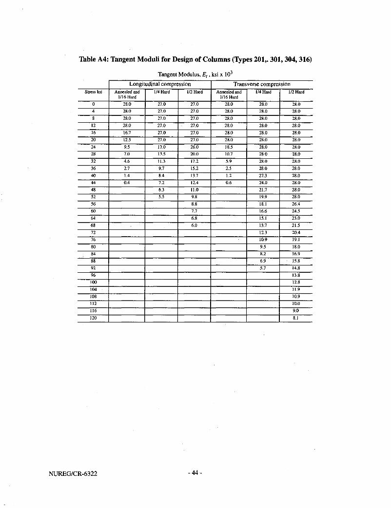
Table A4: Tangent Moduli for Design of Columns (Types 201,. 301,304, 316)
Tangent Modulus, E,, ksi x 10 Longitudinal compression Transverse compression
Stress ksi Annealed and 1/16 Hard
1/4 Hard 1/2 Hard Annealed and 1/16 Hard
1/4 Hard 1/2 Hard
0 28.0 27.0 27.0 28.0 28.0 28.0 4 28.0 27.0 27.0 28.0 28.0 28.0 8 28.0 27.0 27.0 28.0 28.0 28.0 12 28:0 27.0 27.0 28.0 28.0 28.0 16 16.7 27.0 27.0 28.0 28.0 28.0 20 12.5 27.0 27.0 28.0 28.0 28.0 24 9.5 17.0 26.0 18.5 28.0 28.0 28 7.0 13.5 20.0 10.7 28.0 28.0 32 4.6 11.3 17.2 5.9 28.0 28.0 36 2.7 9.7 15.2 2.5 28.0 28.0 40 1.4 8.4 13.7 1.2 27.3 28.0 44 0.4 7.2 12.4 0.6 24.0 28.0 48 6.3 11.0 21.7 28.0 52 5.5 9.8 19.9 28.0 56 8.8 18.1 26.4 60 7.7 16.6 24.5 64 6.8 15.1 23.0 68 6.0 13.7 21.5 72 12.3 20.4 76 10.9 19.1 80 9.5 18.0
8 4 8.2 16.9 88 6.9 15.8 92 5.7 14.8 96 13.8 100 12.8 104 11.9 108 10.9 112 10.0 116 9.0 120 8.1
NUREG/CR-6322 -44-
NRC FORM 335 <2-89l NftCM 1102. 3201. 3202
U.S. NUCLEAR REGULATORY COMMISSION
BIBLIOGRAPHIC DATA SHEET (See instructions on the reverse)
2. T I T L E ANO SUBTITLE
Buckling Analysis of Spent Fuel Basket
1. REPORT NUMBER <Ai.lgc.ed by NRC. Add Vol.. Supp Re* and Addendum Number*. If eny.)
NUREG/CR-6322 UCRL-ID-119697
DATE REPORT PUBLISHED MONTH
May YEAR
2995 4. FIN OR G R A N T NUMBER
A0291 5. AUTHOR (S)
A.S. Lee, S.E. Bumpas
6. TYPE OF REPORT
Technical
7. PERIOD C O V E R E D (Inclusive Dates!
8. PERFORMING O R G A N I Z A T I O N name and mailing address.)
NAME A N D A D D R E S S (If NRC. provide Division, Office or Region, O.S. Nuclear Regulatory Commission, and mailing address; if contractor, provide
Lawrence Livermore National Laboratory P.O. Box 808
Li vermore, CA =94551
9 . SPONSORING O R G A N I Z A T I O N — NAME A N D A D D R E S S (If NRC. type "Same as above"; if contractor, provide NRC Division. Offke or Region. U.S. Nuclear Regulatory Commission, and matting address.)
Division of Industrial and Medical Nuclear Safety Office of Nuclear Material Safety and Safeguards U.S. Nuclear Regulatory Commission Washington, DC 20555-0001
10. SUPPLEMENTARY NOTES
11. ABSTRACT (200 words or less) . . *-u~i- ™=,, The basket for a spent fuel shipping cask xs subjected to compressive stresses that may cause global instability of the basket assemblies or local buckling of the individual members. Adopting the common buckling design practice in which the stability capacity of the entire structure is based on the performance of the individual members of the assemblies, the typical spent fuel basket, which is composed of plates and tubular stuctural members, can be idealized as an assemblage of columns, beam-columns and plates This report presents the flexural buckling formulas for five load cases that are common in the basket buckling analysis: column xinder axial loads, column under axial and bendin< -loads, plates under uniaxial loads, plates under biaxial loadings, and plate under biaxial loads and lateral pressure.. The acceptance criteria from the ASME Boiler and Pressure Vessel Code are used to determine the adequacy of the basket components. Special acceptance criteria are proposed to address the unique material characteristics of austenitic stainless steel, a material which is frequently used in the basket assemblies.
12. KEY W O R O S / O E S C R I P T O R S (List words or phrases that will assist researchers In locating the report.)
Shipping Casks, Spent Fuel Baskets, Buckling Analysis, Austenitic Stainless Steel
13. AVAILABILITY STATEMENT
Unlimited 14. SECURITY CLASSIFICATION
(This Page)
Unclassified (This Report!
Unclassified 15. NUMBER OF PAGES
16. PRICE
w n c FORM 33S {2-891