BTS3900 Site Maintenance Terminal User Guide-(V300R008_02)
148
BTS3900 V300R008 Site Maintenance Terminal User Guide Issue 02 Date 2008-04-30 Part Number Huawei Proprietary and Confidential Copyright © Huawei Technologies Co., Ltd
Transcript of BTS3900 Site Maintenance Terminal User Guide-(V300R008_02)

8/10/2019 BTS3900 Site Maintenance Terminal User Guide-(V300R008_02)
http://slidepdf.com/reader/full/bts3900-site-maintenance-terminal-user-guide-v300r00802 1/147
BTS3900
V300R008
Site Maintenance Terminal User Guide
Issue 02
Date 2008-04-30
Part Number
Huawei Proprietary and Confidential
Copyright © Huawei Technologies Co., Ltd

8/10/2019 BTS3900 Site Maintenance Terminal User Guide-(V300R008_02)
http://slidepdf.com/reader/full/bts3900-site-maintenance-terminal-user-guide-v300r00802 2/147
Huawei Technologies Co., Ltd. provides customers with comprehensive technical support and service. For any
assistance, please contact our local office or company headquarters.
Huawei Technologies Co., Ltd.
Address: Huawei Industrial Base
Bantian, Longgang
Shenzhen 518129
People's Republic of China
Website: http://www.huawei.com
Email: [email protected]
Copyright © Huawei Technologies Co., Ltd. 2008. All rights reserved.
No part of this document may be reproduced or transmitted in any form or by any means without prior written
consent of Huawei Technologies Co., Ltd.
Trademarks and Permissions
and other Huawei trademarks are the property of Huawei Technologies Co., Ltd.
All other trademarks and trade names mentioned in this document are the property of their respective holders.
Notice
The information in this document is subject to change without notice. Every effort has been made in the
preparation of this document to ensure accuracy of the contents, but the statements, information, and
recommendations in this document do not constitute a warranty of any kind, express or implied.
Huawei Proprietary and Confidential
Copyright © Huawei Technologies Co., Ltd

8/10/2019 BTS3900 Site Maintenance Terminal User Guide-(V300R008_02)
http://slidepdf.com/reader/full/bts3900-site-maintenance-terminal-user-guide-v300r00802 3/147
Contents
About This Document.....................................................................................................................1
1 Introduction to the Site Maintenance Terminal...................................................................1-1
1.1 Definitions Related to the Site Maintenance Terminal...................................................................................1-2
1.2 Logical O bjects of the BTS.............................................................................................................................1-21.3 Software Window of the Site Maintenance Terminal System........................................................................1-3
2 Getting Started with the Site Maintenance Terminal.........................................................2-1
2.1 Configuration Requirements for the Site Maintenance Terminal PC.............................................................2-2
2.2 Starting the Site Maintenance Terminal System.............................................................................................2-3
2.2.1 Setting the IP Address of the Site Maintenance Terminal PC...............................................................2-3
2.2.2 Connecting the Site Maintenance Terminal PC to the BTS...................................................................2-4
2.2.3 Locally Logging In to the BTS..............................................................................................................2-4
2.3 Exiting the Site Maintenance Terminal...........................................................................................................2-6
3 Using the Site Management Rights........................................................................................3-13.1 Site Management Rights.................................................................................................................................3-2
3.2 Obtaining the Site Management Rights..........................................................................................................3-2
3.3 Releasing the Site Management Rights...........................................................................................................3-3
4 Managing Sites...........................................................................................................................4-1
4.1 Viewing Site Resources..................................................................................................................................4-3
4.2 Forcibly Loading Software..............................................................................................................................4-4
4.3 Activating Software.........................................................................................................................................4-5
4.4 Resetting a Site Hierarchically........................................................................................................................4-8
4.5 Monitoring Environment.................................................................................................................................4-9
4.6 Testing Tr ansport Performance.....................................................................................................................4-11
4.7 Querying Alarm Delay Time.........................................................................................................................4-13
4.8 Testing the RF Specifications.......................................................................................................................4-14
4.9 Querying the Ring Topology Parameters......................................................................................................4-16
4.10 Viewing the Bar Codes...............................................................................................................................4-17
4.11 Managing the Site Board Parameters..........................................................................................................4-19
4.12 Testing the E1 BER.....................................................................................................................................4-20
4.13 Managing the RET Antenna........................................................................................................................4-21
5 Managing Cells...........................................................................................................................5-1
BTS3900
Site Maintenance Terminal User Guide Contents
Issue 02 (2008-04-30) Huawei Proprietary and Confidential
Copyright © Huawei Technologies Co., Ltd
i
8/10/2019 BTS3900 Site Maintenance Terminal User Guide-(V300R008_02)
http://slidepdf.com/reader/full/bts3900-site-maintenance-terminal-user-guide-v300r00802 4/147
5.1 Managing Cell Attributes................................................................................................................................5-2
5.2 Managing Cell Extended Attributes................................................................................................................5-5
5.3 Changing the Cell Management State.............................................................................................................5-7
5.4 Performing the Cell Performance Test............................................................................................................5-8
6 Managing BTs.............................................................................................................................6-1
6.1 Changing the BT Management State..............................................................................................................6-2
6.2 Re-Initializing a BT.........................................................................................................................................6-3
6.3 Performing BT Tests.......................................................................................................................................6-4
6.4 Viewing the Channel Status............................................................................................................................6-4
6.5 Setting the TRX Full Power Emission............................................................................................................6-5
7 Managing RCs.............................................................................................................................7-1
7.1 Managing RC Attributes.................................................................................................................................7-2
7.2 Managing RC Extended Attributes.................................................................................................................7-37.3 Changing the RC Management State..............................................................................................................7-5
7.4 Re-Initializing an RC......................................................................................................................................7-6
7.5 Obtaining the RC Power Mode.......................................................................................................................7-7
7.6 Obtaining the Auto Power Adjustment Type..................................................................................................7-8
8 Managing Channels...................................................................................................................8-1
8.1 Managing Channel Attributes.........................................................................................................................8-2
8.2 Changing the Channel Management State......................................................................................................8-3
8.3 Performing the Loopback Test........................................................................................................................8-4
9 BBU Operations..........................................................................................................................9-1
9.1 Configuring a Board........................................................................................................................................9-3
9.2 Querying Board Information...........................................................................................................................9-4
9.3 Querying Board Extended Information...........................................................................................................9-5
9.4 Resetting a board.............................................................................................................................................9-7
9.5 Resetting a Board in Power-Off Mode............................................................................................................9-8
9.6 Testing a Board.............................................................................................................................................9-10
9.7 Setting the BTS Clock...................................................................................................................................9-11
9.8 Performing Loopback Test of Board Communication Links........................................................................9-13
9.9 Querying Board Alarms................................................................................................................................9-15
9.10 Querying Board Parameters........................................................................................................................9-17
9.11 Querying Port Attributes.............................................................................................................................9-18
10 DRFU Operations...................................................................................................................10-1
10.1 Viewing Board Information........................................................................................................................10-3
10.2 Viewing Board Extended Information........................................................................................................10-4
10.3 Resetting a Board in Power-Off Mode........................................................................................................10-7
10.4 Resetting a Board........................................................................................................................................10-9
10.5 Starting a Board.........................................................................................................................................10-12
10.6 Testing a Board.........................................................................................................................................10-14
Contents
BTS3900
Site Maintenance Terminal User Guide
ii Huawei Proprietary and Confidential
Copyright © Huawei Technologies Co., Ltd
Issue 02 (2008-04-30)

8/10/2019 BTS3900 Site Maintenance Terminal User Guide-(V300R008_02)
http://slidepdf.com/reader/full/bts3900-site-maintenance-terminal-user-guide-v300r00802 5/147

8/10/2019 BTS3900 Site Maintenance Terminal User Guide-(V300R008_02)
http://slidepdf.com/reader/full/bts3900-site-maintenance-terminal-user-guide-v300r00802 6/147
8/10/2019 BTS3900 Site Maintenance Terminal User Guide-(V300R008_02)
http://slidepdf.com/reader/full/bts3900-site-maintenance-terminal-user-guide-v300r00802 7/147
Figures
Figure 1-1 Logical structure of a BTS..................................................................................................................1-2
Figure 1-2 Site Maintenance Terminal System Software Window......................................................................1-3
Figure 2-1 Communication failed dialog box......................................................................................................2-5
Figure 2-2 Site Maintenance Terminal System window......................................................................................2-5
Figure 2-3 Set Communication Port Parameter dialog box.................................................................................2-6
Figure 3-1 Site Management Right dialog box....................................................................................................3-3
Figure 3-2 Site Management Right dialog box....................................................................................................3-4
Figure 4-1 View Resource dialog box........................................................................................ ..........................4-3
Figure 4-2 Software Download dialog box..........................................................................................................4-5
Figure 4-3 Software Activation dialog box..........................................................................................................4-7
Figure 4-4 Software Activation dialog box..........................................................................................................4-7
Figure 4-5 Site Reset Hierarchically dialog box..................................................................................................4-9
Figure 4-6 Environment Monitor dialog box.....................................................................................................4-11
Figure 4-7 Tr ansport Performance Test dialog box...........................................................................................4-13Figure 4-8 Query Warn Delay Time dialog box................................................................................................4-14
Figure 4-9 R F Specification Test window.........................................................................................................4-16
Figure 4-10 R ing Topology Parameter Query dialog box..................................................................................4-17
Figure 4-11 Bar Code Query dialog box............................................................................................................4-18
Figure 4-12 Site Board Parameter Management dialog box..............................................................................4-19
Figure 4-13 Site Board Parameter Management dialog box..............................................................................4-20
Figure 4-14 E1 BER Test dialog box.................................................................................................................4-21
Figure 4-15 R ET Antenna Manage dialog box..................................................................................................4-22
Figure 5-1 Cell Attributes Management dialog box.............................................................................................5-4
Figure 5-2 Cell Extended Attributes Management dialog box.............................................................................5-6
Figure 5-3 Change Cell Management State dialog box........................................................................................5-7
Figure 5-4 Cell Test dialog box............................................................................................................................5-8
Figure 6-1 Change BT Management State dialog box.........................................................................................6-2
Figure 6-2 BT Reinitialization dialog box...........................................................................................................6-3
Figure 6-3 BT Loop Test dialog box....................................................................................................................6-4
Figure 6-4 View Channel State dialog box..........................................................................................................6-5
Figure 6-5 TRX Full Power Emission dialog box................................................................................................6-6
Figure 7-1 RC Attributes Management dialog box..............................................................................................7-3
Figure 7-2 RC Extended Attributes Management dialog box..............................................................................7-4
BTS3900
Site Maintenance Terminal User Guide Figures
Issue 02 (2008-04-30) Huawei Proprietary and Confidential
Copyright © Huawei Technologies Co., Ltd
v
8/10/2019 BTS3900 Site Maintenance Terminal User Guide-(V300R008_02)
http://slidepdf.com/reader/full/bts3900-site-maintenance-terminal-user-guide-v300r00802 8/147
Figure 7-3 Change RC Management State dialog box.........................................................................................7-6
Figure 7-4 RC Reinitialization dialog box...........................................................................................................7-7
Figure 7-5 Get RC Power Mode dialog box.........................................................................................................7-7
Figure 7-6 Get Auto Power Adjustment Type dialog box................................................................................... 7-8
Figure 8-1 Channel Attributes Management dialog box......................................................................................8-3
Figure 8-2 Change Channel Management State dialog box.................................................................................8-4
Figure 8-3 Channel Loop Test dialog box............................................................................................................8-6
Figure 9-1 Board Configuration window.............................................................................................................9-4
Figure 9-2 Board Management window...............................................................................................................9-5
Figure 9-3 Board Information dialog box............................................................................................................ 9-5
Figure 9-4 Board Management window...............................................................................................................9-6
Figure 9-5 Board Extended Information dialog box............................................................................................9-7
Figure 9-6 Board Management window...............................................................................................................9-8
Figure 9-7 Board Reset window...........................................................................................................................9-8
Figure 9-8 Board Management window...............................................................................................................9-9
Figure 9-9 Board Reset window.........................................................................................................................9-10
Figure 9-10 Board Management window...........................................................................................................9-10
Figure 9-11 Board Test dialog box.....................................................................................................................9-11
Figure 9-12 Board Management window...........................................................................................................9-12
Figure 9-13 Clock Setup dialog box...................................................................................................................9-13
Figure 9-14 Board Management window...........................................................................................................9-14
Figure 9-15 Loop Test dialog box......................................................................................................................9-15
Figure 9-16 Board Management window...........................................................................................................9-16Figure 9-17 Board Alarm Information dialog box.............................................................................................9-16
Figure 9-18 Board Management window...........................................................................................................9-17
Figure 9-19 Parameter Management dialog box................................................................................................9-18
Figure 9-20 Board Management window...........................................................................................................9-19
Figure 9-21 GTMU port property window.........................................................................................................9-19
Figure 10-1 Board Management window...........................................................................................................10-3
Figure 10-2 Topology Management window.....................................................................................................10-4
Figure 10-3 Board information...........................................................................................................................10-4
Figure 10-4 Board Management window...........................................................................................................10-5
Figure 10-5 Topology Management window.....................................................................................................10-6
Figure 10-6 Board Extended Information dialog box........................................................................................10-6
Figure 10-7 Board Management window...........................................................................................................10-7
Figure 10-8 Topology Management window.....................................................................................................10-8
Figure 10-9 Choosing Power Off Reset.............................................................................................................10-8
Figure 10-10 Board Reset window.....................................................................................................................10-9
Figure 10-11 Board Management window.......................................................................................................10-10
Figure 10-12 Topology Management window.................................................................................................10-10
Figure 10-13 Choosing Reset...........................................................................................................................10-11
Figure 10-14 Board Reset window...................................................................................................................10-11
Figures
BTS3900
Site Maintenance Terminal User Guide
vi Huawei Proprietary and Confidential
Copyright © Huawei Technologies Co., Ltd
Issue 02 (2008-04-30)

8/10/2019 BTS3900 Site Maintenance Terminal User Guide-(V300R008_02)
http://slidepdf.com/reader/full/bts3900-site-maintenance-terminal-user-guide-v300r00802 9/147
Figure 10-15 Reset dialog box.........................................................................................................................10-11
Figure 10-16 Board Management window.......................................................................................................10-12
Figure 10-17 Topology Management window.................................................................................................10-13
Figure 10-18 Choosing Opstart........................................................................................................................10-13
Figure 10-19 Opstart dialog box......................................................................................................................10-14
Figure 10-20 Board Management window.......................................................................................................10-14
Figure 10-21 Topology Management window.................................................................................................10-15
Figure 10-22 Choosing the path to be tested....................................................................................................10-15
Figure 10-23 Board Test dialog box.................................................................................................................10-16
Figure 10-24 Board Management window.......................................................................................................10-16
Figure 10-25 Topology Management window.................................................................................................10-17
Figure 10-26 Choosing Management state.......................................................................................................10-17
Figure 10-27 LOCKED dialog box..................................................................................................................10-18
Figure 10-28 UNLOCKED dialog box............................................................................................................10-18
Figure 10-29 Choosing Management state.......................................................................................................10-19
Figure 10-30 Channel0LOCKED dialog box...................................................................................................10-19
Figure 10-31 Board Management window.......................................................................................................10-20
Figure 10-32 Topology Management window.................................................................................................10-21
Figure 10-33 Choosing Loop Test....................................................................................................................10-21
Figure 10-34 Loop Test dialog box..................................................................................................................10-22
Figure 10-35 Board Management window.......................................................................................................10-23
Figure 10-36 Topology Management window.................................................................................................10-23
Figure 10-37 Board Alarm Information dialog box.........................................................................................10-24Figure 10-38 Board Management window.......................................................................................................10-25
Figure 10-39 Topology Management window.................................................................................................10-25
Figure 10-40 Choosing Parameter Management..............................................................................................10-26
Figure 10-41 Viewing the operational parameters...........................................................................................10-26
Figure 10-42 Viewing the configuration parameters........................................................................................10-27
Figure 10-43 Setting the parameters................................................................................................................10-27
Figure 10-44 Viewing the operational parameters of a path............................................................................10-28
Figure 10-45 Board Management window.......................................................................................................10-29
Figure 10-46 Topology Management window.................................................................................................10-29
Figure 10-47 Choosing Set Antenna Mode......................................................................................................10-30
Figure 10-48 Set Antenna Mode window........................................................................................................10-30
Figure 11-1 Board Configuration window.........................................................................................................11-2
Figure 11-2 Topology Configuration window...................................................................................................11-3
Figure 11-3 Deploy DRRU window..................................................................................................................11-3
Figure 11-4 Deploy DRRU window..................................................................................................................11-4
Figure 11-5 Topology Configuration window...................................................................................................11-4
Figure 11-6 Board Configuration window.........................................................................................................11-5
Figure 11-7 Topology Configuration window...................................................................................................11-5
Figure 11-8 Delete DRRU window....................................................................................................................11-6
BTS3900
Site Maintenance Terminal User Guide Figures
Issue 02 (2008-04-30) Huawei Proprietary and Confidential
Copyright © Huawei Technologies Co., Ltd
vii

8/10/2019 BTS3900 Site Maintenance Terminal User Guide-(V300R008_02)
http://slidepdf.com/reader/full/bts3900-site-maintenance-terminal-user-guide-v300r00802 10/147
Figure 11-9 Board Configuration window.........................................................................................................11-7
Figure 11-10 Topology Configuration window.................................................................................................11-7
Figure 11-11 Add Ring window.........................................................................................................................11-8
Figure 11-12 Board Configuration window.......................................................................................................11-9
Figure 11-13 Topology Configuration window.................................................................................................11-9
Figure 11-14 Divide Ring window...................................................................................................................11-10
Figure 11-15 Board Management window.......................................................................................................11-11
Figure 11-16 Board Management window.......................................................................................................11-12
Figure 11-17 Topology Management window.................................................................................................11-12
Figure 11-18 On-Site Topology Management window...................................................................................11-13
Figure 11-19 Board Management window.......................................................................................................11-14
Figure 11-20 Topology Management window.................................................................................................11-14
Figure 11-21 Choosing Set Breakpoint............................................................................................................11-15
Figure 11-22 Board Management window.......................................................................................................11-16
Figure 11-23 Topology Management window.................................................................................................11-16
Figure 11-24 Choosing Cancel Breakpoint......................................................................................................11-17
Figures
BTS3900
Site Maintenance Terminal User Guide
viii Huawei Proprietary and Confidential
Copyright © Huawei Technologies Co., Ltd
Issue 02 (2008-04-30)

8/10/2019 BTS3900 Site Maintenance Terminal User Guide-(V300R008_02)
http://slidepdf.com/reader/full/bts3900-site-maintenance-terminal-user-guide-v300r00802 11/147
Tables
Table 2-1 Hardware requirements........................................................................................................................2-2
Table 2-2 Software requirements......................................................................................................................... 2-2
Table 4-1 Parameters available in the Software Download dialog box................................................................4-4
Table 4-2 Parameters in the Software Activation dialog box...............................................................................4-6
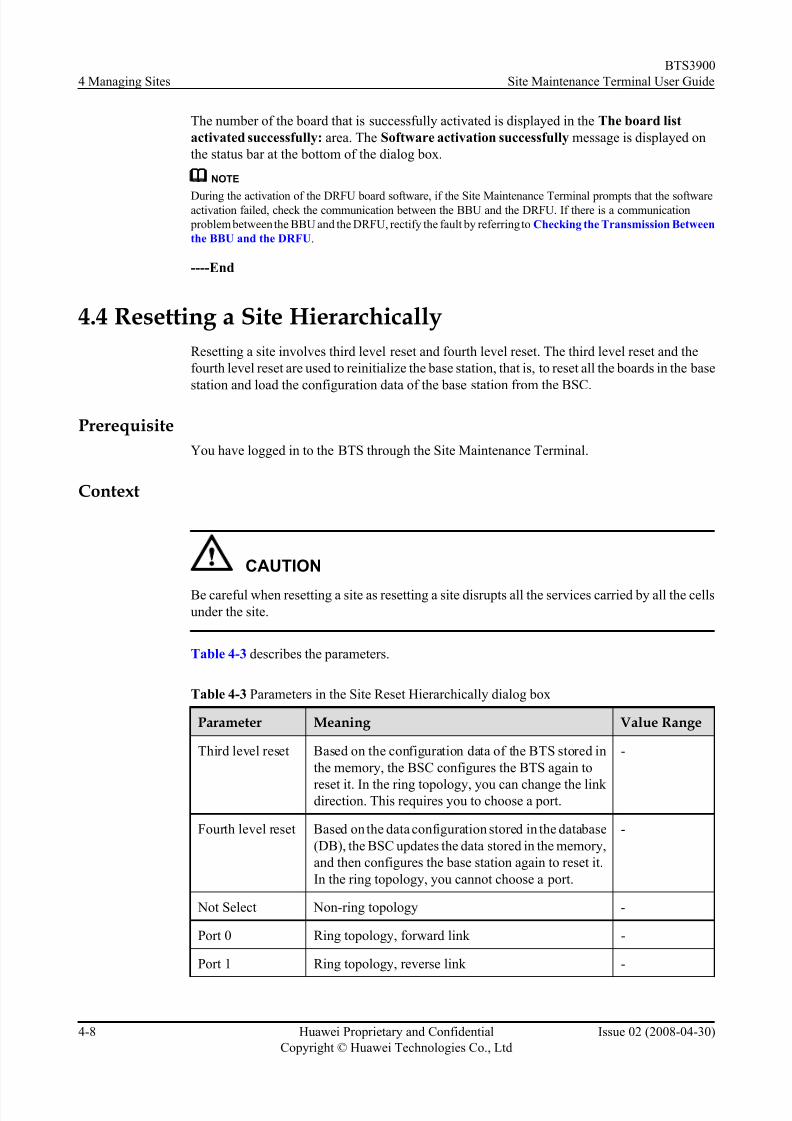
Table 4-3 Parameters in the Site Reset Hierarchically dialog box.......................................................................4-8
Table 4-4 Parameters in the Environment Monitor dialog box..........................................................................4-10
Table 4-5 Parameters in the Transport Performance Test dialog box................................................................4-12
Table 5-1 Parameters in the Cell Attributes Management dialog box..................................................................5-2
Table 5-2 Parameters in the Cell Extended Attributes Management dialog box................................................. 5-5
Table 7-1 Parameters in the RC Attributes Management dialog box...................................................................7-2
Table 7-2 Parameters in the RC Extended Attribute Management dialog box.................................................... 7-4
Table 8-1 Parameters in the Channel Attributes Management dialog box...........................................................8-2
Table 8-2 Parameters in the Cell Extended Attributes Management dialog box................................................. 8-5
Table 9-1 Par ameters in the Clock Setup dialog box.........................................................................................9-11Table 9-2 Par ameters in the Loopback Test dialog box.....................................................................................9-14
Table 10-1 Parameters in the Loop Test dialog box.........................................................................................10-20
BTS3900
Site Maintenance Terminal User Guide Tables
Issue 02 (2008-04-30) Huawei Proprietary and Confidential
Copyright © Huawei Technologies Co., Ltd
ix

8/10/2019 BTS3900 Site Maintenance Terminal User Guide-(V300R008_02)
http://slidepdf.com/reader/full/bts3900-site-maintenance-terminal-user-guide-v300r00802 12/147

8/10/2019 BTS3900 Site Maintenance Terminal User Guide-(V300R008_02)
http://slidepdf.com/reader/full/bts3900-site-maintenance-terminal-user-guide-v300r00802 13/147
About This Document
Purpose
This document describes the procedures for installing the BTS3900 Site Maintenance Terminal.
It also describes the functions and interfaces of the different parts of the BTS3900 Site
Maintenance Terminal. In addition, it gives instructions for common BTS3900 operations.
Product Version
The following table lists the product version related to the document.
Product Name Product Version
BTS3900 V300R008
Intended Audience
This guide is intended for the engineers who maintain the BTS through the site maintenance
terminal. The engineers should have a basic knowledge of radio communication and IP
technologies, and be familiar with Windows operations and the BTS. This document is intended
for:
l System engineers
l Field engineers
l Shift operators
l Network operators
Change History
For changes in the document, refer to Changes in BTS3900 Site Maintenance Terminal User
Guide.
Organization
1 Introduction to the Site Maintenance Terminal
This describes the definitions, functions, logical objects, and software window of the Site
Maintenance Terminal. The Site Maintenance Terminal is used to commission, maintain, and
troubleshoot a BTS.
2 Getting Started with the Site Maintenance Terminal
BTS3900
Site Maintenance Terminal User Guide About This Document
Issue 02 (2008-04-30) Huawei Proprietary and Confidential
Copyright © Huawei Technologies Co., Ltd
1

8/10/2019 BTS3900 Site Maintenance Terminal User Guide-(V300R008_02)
http://slidepdf.com/reader/full/bts3900-site-maintenance-terminal-user-guide-v300r00802 14/147
This describes how to connect the Site Maintenance Terminal PC to the BTS, log in to the Site
Maintenance Terminal System, and exit the Site Maintenance Terminal, after the Site
Maintenance Terminal application is installed.
3 Using the Site Management Rights
The operations of the site management rights involve obtaining the site management rights and
releasing the site management rights.
4 Managing Sites
The site management involves viewing site resources, querying the delay in reporting board
alarms, resetting the BTS, testing whether the boards in a site operate normally and whether the
connection of transmit links is normal, monitoring and managing the environment parameters
in a site, viewing the board parameters of the BTS, testing the RF specifications, and viewing
the settings of parameters in a ring network and the bar codes of a site.
5 Managing Cells
The cell management involves managing cell attributes and cell extended attributes, testing all
the BTs and RCs of a cell so that they can be locked or unlocked, and checking whether the BTs
and RCs are functional.
6 Managing BTs
The BT management involves locking or unlocking a BT, resetting a BT, performing the RC
self-test, view the status of the channels on a specified BT, and enabling a specified RC to
transmit signals at a predefined power level.
7 Managing RCs
The RC management involves setting the attributes and extended attributes of an RC, lockingor unlocking an RC, resetting an RC, and adjusting power of an RC automatically.
8 Managing Channels
The channel management involves viewing and setting channel attributes, locking or unlocking
a channel, and checking the quality of a channel by testing the parameters such as the bit error
ratio (BER) and transmit power.
9 BBU Operations
The BBU operations involve the query, configuration, and test operations associated with the
BBU. You can query the board settings, board information, board extended information, board
alarms, and port attributes. You can also perform operations such as board reset, power-off reset,self-test, clock configuration, loopback test, and parameter management.
10 DRFU Operations
DRFU operations include the viewing, setting and testing of the DRFU parameters. You can
view the board information, board extended information, and board alarms. You can also
perform operations such as the board reset, power-off reset, operation start, self-test, loopback
test, parameter management, and antenna mode configuration.
11 DRFU Configuration
This describes how to perform various operations on the DRFU based on the actual requirement,
such as adding or deleting an DRFU, adding or removing a ring, displaying in-position boards,detecting in-position boards, setting and canceling a breakpoint.
About This Document
BTS3900
Site Maintenance Terminal User Guide
2 Huawei Proprietary and Confidential
Copyright © Huawei Technologies Co., Ltd
Issue 02 (2008-04-30)

8/10/2019 BTS3900 Site Maintenance Terminal User Guide-(V300R008_02)
http://slidepdf.com/reader/full/bts3900-site-maintenance-terminal-user-guide-v300r00802 15/147
Conventions
1. Symbol Conventions
The following symbols may be found in this document. They are defined as follows
Symbol Description
DANGER
Indicates a hazard with a high level of risk that, if not avoided,
will result in death or serious injury.
WARNING
Indicates a hazard with a medium or low level of risk which, if
not avoided, could result in minor or moderate injury.
CAUTION
Indicates a potentially hazardous situation that, if not avoided,
could cause equipment damage, data loss, and performancedegradation, or unexpected results.
TIP Indicates a tip that may help you solve a problem or save your
time.
NOTE Provides additional information to emphasize or supplement
important points of the main text.
2. General Conventions
Convention Description
Times New Roman Normal paragraphs are in Times New Roman.
Boldface Names of files,directories,folders,and users are in boldface. For
example,log in as user root .
Italic Book titles are in italics.
Courier New Terminal display is in Courier New.
3. Command Conventions
Convention Description
Boldface The keywords of a command line are in boldface.
Italic Command arguments are in italic.
[ ] Items (keywords or arguments) in square brackets [ ] are optional.
{x | y | ...} Alternative items are grouped in braces and separated by vertical
bars.One is selected.
[ x | y | ... ] Optional alternative items are grouped in square brackets and
separated by vertical bars.One or none is selected.
BTS3900
Site Maintenance Terminal User Guide About This Document
Issue 02 (2008-04-30) Huawei Proprietary and Confidential
Copyright © Huawei Technologies Co., Ltd
3

8/10/2019 BTS3900 Site Maintenance Terminal User Guide-(V300R008_02)
http://slidepdf.com/reader/full/bts3900-site-maintenance-terminal-user-guide-v300r00802 16/147
Convention Description
{ x | y | ... } * Alternative items are grouped in braces and separated by vertical
bars.A minimum of one or a maximum of all can be selected.
[ x | y | ... ] * Alternative items are grouped in braces and separated by vertical
bars.A minimum of zero or a maximum of all can be selected.
4. GUI Conventions
Convention Description
Boldface Buttons,menus,parameters,tabs,window,and dialog titles are in
boldface. For example,click OK .
> Multi-level menus are in boldface and separated by the ">" signs.
For example,choose File > Create > Folder .
5. Keyboard Operation
Convention Description
Key Press the key.For example,press Enter and press Tab.
Key1+Key2 Press the keys concurrently.For example,pressing Ctrl+Alt+A
means the three keys should be pressed concurrently.
Key1,Key2 Press the keys in turn.For example,pressing Alt,A means the two
keys should be pressed in turn.
6. Mouse Operation
Action Description
Click Select and release the primary mouse button without moving the
pointer.
Double-click Press the primary mouse button twice continuously and quickly
without moving the pointer.
Drag Press and hold the primary mouse button and move the pointer
to a certain position.
About This Document
BTS3900
Site Maintenance Terminal User Guide
4 Huawei Proprietary and Confidential
Copyright © Huawei Technologies Co., Ltd
Issue 02 (2008-04-30)
8/10/2019 BTS3900 Site Maintenance Terminal User Guide-(V300R008_02)
http://slidepdf.com/reader/full/bts3900-site-maintenance-terminal-user-guide-v300r00802 17/147
1 Introduction to the Site Maintenance
Terminal
About This Chapter
This describes the definitions, functions, logical objects, and software window of the Site
Maintenance Terminal. The Site Maintenance Terminal is used to commission, maintain, and
troubleshoot a BTS.
The Site Maintenance Terminal provides a graphical user interface (GUI) for operation and
maintenance.
1.1 Definitions Related to the Site Maintenance TerminalThis describes the difference between the Site Maintenance Terminal, Site Maintenance
Terminal PC, and Site Maintenance Terminal application.
1.2 Logical Objects of the BTS
This describes the logical objects of the BTS. Different logical objects are maintained in different
ways.
1.3 Software Window of the Site Maintenance Terminal System
The Site Maintenance Terminal System software window consists of the navigation pane,
browse pane, and status pane.
BTS3900
Site Maintenance Terminal User Guide 1 Introduction to the Site Maintenance Terminal
Issue 02 (2008-04-30) Huawei Proprietary and Confidential
Copyright © Huawei Technologies Co., Ltd
1-1

8/10/2019 BTS3900 Site Maintenance Terminal User Guide-(V300R008_02)
http://slidepdf.com/reader/full/bts3900-site-maintenance-terminal-user-guide-v300r00802 18/147
1.1 Definitions Related to the Site Maintenance Terminal
This describes the difference between the Site Maintenance Terminal, Site MaintenanceTerminal PC, and Site Maintenance Terminal application.
Site Maintenance Terminal
The Site Maintenance Terminal is a logical concept. It refers to a maintenance terminal installed
with the Site Maintenance Terminal software package and connected to the OM network of the
BTSs. Through the Site Maintenance Terminal, you can operate and maintain the BTSs.
Site Maintenance Terminal PC
The Site Maintenance Terminal PC is a hardware concept. It refers to the computer on whichthe Site Maintenance Terminal software package is installed.
Site Maintenance Terminal Application
The Site Maintenance Terminal application is installed on a Site Maintenance Terminal PC. It
refers to the Huawei Site Maintenance Terminal software package.
1.2 Logical Objects of the BTS
This describes the logical objects of the BTS. Different logical objects are maintained in different
ways.
The logical objects consist of the sites, cells, baseband (BTs), channels (CHs), and TRXs (RCs),
as shown in Figure 1-1.
Figure 1-1 Logical structure of a BTS
1 Introduction to the Site Maintenance Terminal
BTS3900
Site Maintenance Terminal User Guide
1-2 Huawei Proprietary and Confidential
Copyright © Huawei Technologies Co., Ltd
Issue 02 (2008-04-30)

8/10/2019 BTS3900 Site Maintenance Terminal User Guide-(V300R008_02)
http://slidepdf.com/reader/full/bts3900-site-maintenance-terminal-user-guide-v300r00802 19/147
1.3 Software Window of the Site Maintenance TerminalSystem
The Site Maintenance Terminal System software window consists of the navigation pane,
browse pane, and status pane.
The Site Maintenance Terminal System software window consists of the navigation pane,
browse pane, and status pane, as shown in Figure 1-2.
Figure 1-2 Site Maintenance Terminal System Software Window
BTS3900
Site Maintenance Terminal User Guide 1 Introduction to the Site Maintenance Terminal
Issue 02 (2008-04-30) Huawei Proprietary and Confidential
Copyright © Huawei Technologies Co., Ltd
1-3

8/10/2019 BTS3900 Site Maintenance Terminal User Guide-(V300R008_02)
http://slidepdf.com/reader/full/bts3900-site-maintenance-terminal-user-guide-v300r00802 20/147

8/10/2019 BTS3900 Site Maintenance Terminal User Guide-(V300R008_02)
http://slidepdf.com/reader/full/bts3900-site-maintenance-terminal-user-guide-v300r00802 21/147

8/10/2019 BTS3900 Site Maintenance Terminal User Guide-(V300R008_02)
http://slidepdf.com/reader/full/bts3900-site-maintenance-terminal-user-guide-v300r00802 22/147
2.1 Configuration Requirements for the Site MaintenanceTerminal PC
The Site Maintenance Terminal PC should meet the requirements for the configuration of
hardware and software and for the communication capability.
Hardware Requirements
Table 2-1 lists the hardware requirements for the installation of the Site Maintenance Terminal
PC.
Table 2-1 Hardware requirements
Item Quantity MinimumConfiguration
CPU 1 PIII 866
RAM 1 256 MB
Hard disk 1 20 GB
Display adapter resolution 1 800×600
Ethernet adapter 1 10&100Mbps
CD drive - -
Other devices 3×1 Keyboard,
mouse, modem
Software Requirements
Table 2-2 lists the software requirements for the installation of the Site Maintenance Terminal
PC.
Table 2-2 Software requirements
Item RecommendedConfiguration
Operating system Microsoft Windows
98/2000/XP
Default language of the operating system English (United States)
Web browser Microsoft Internet
Explorer 5.5 or later
versions
2 Getting Started with the Site Maintenance Terminal
BTS3900
Site Maintenance Terminal User Guide
2-2 Huawei Proprietary and Confidential
Copyright © Huawei Technologies Co., Ltd
Issue 02 (2008-04-30)

8/10/2019 BTS3900 Site Maintenance Terminal User Guide-(V300R008_02)
http://slidepdf.com/reader/full/bts3900-site-maintenance-terminal-user-guide-v300r00802 23/147
Communications Capability Requirements
The Site Maintenance Terminal PC should support the TCP/IP protocol.
2.2 Starting the Site Maintenance Terminal SystemBefore starting the Site Maintenance Terminal, firstly, set the IP address of the Site Maintenance
Terminal PC; secondly, connect the Site Maintenance Terminal PC to the BTS; finally, log in
to the Site Maintenance Terminal.
1. 2.2.1 Setting the IP Address of the Site Maintenance Terminal PC
This describes how to set the IP address of the Site Maintenance Terminal PC to the same
network segment as the IP address (192.168.0.72/255.255.255.0) of the BTS.
2. 2.2.2 Connecting the Site Maintenance Terminal PC to the BTS
To operate and maintain the BTS on the Site Maintenance Terminal, the Site Maintenance
Terminal PC should be connected to the ETH port on the main control module of the BTS
using the crossover cable.
3. 2.2.3 Locally Logging In to the BTS
You can run the Site Maintenance Terminal to directly log in to the BTS.
2.2.1 Setting the IP Address of the Site Maintenance Terminal PC
This describes how to set the IP address of the Site Maintenance Terminal PC to the same network
segment as the IP address (192.168.0.72/255.255.255.0) of the BTS.
PrerequisiteThe Site Maintenance Terminal PC is configured with the TCP/IP protocol.
Procedure
Step 1 Take the Windows XP operating system as an example. On the Windows XP operating system,
choose Start > Control Panel.
Step 2 Select Network Connections. A dialog box is displayed. Right-click the Local Area
Connection icon.
Step 3 Choose Properties on the shortcut menu,. The Local Area Connection Properties dialog box
is displayed.
Step 4 Select Internet Protocol (TCP/IP).
Step 5 Click Properties. The Internet Protocol (TCP/IP) Properties dialog box is displayed.
Step 6 Select Use the following IP address.
Step 7 Enter the correct IP address, subnet mask, and default gateway. Ensure that the IP address of the
Site Maintenance Terminal PC and the IP address (192.168.0.72/255.255.255.0) of the BTS are
located in the same network segment, so that a local maintenance path can be set up.
Step 8 Click OK to complete the setting.
----End
BTS3900
Site Maintenance Terminal User Guide 2 Getting Started with the Site Maintenance Terminal
Issue 02 (2008-04-30) Huawei Proprietary and Confidential
Copyright © Huawei Technologies Co., Ltd
2-3

8/10/2019 BTS3900 Site Maintenance Terminal User Guide-(V300R008_02)
http://slidepdf.com/reader/full/bts3900-site-maintenance-terminal-user-guide-v300r00802 24/147
2.2.2 Connecting the Site Maintenance Terminal PC to the BTS
To operate and maintain the BTS on the Site Maintenance Terminal, the Site Maintenance
Terminal PC should be connected to the ETH port on the main control module of the BTS using
the crossover cable.
Prerequisite
The IP address and the subnet mask of the Site Maintenance Terminal PC are set. The IP address
of the Site Maintenance Terminal PC and the IP address (192.168.0.72/255.255.255.0) of the
BTS are on the same network segment.
Procedure
Step 1 Use the crossover cable to connect the Site Maintenance Terminal PC to the BTS. Connect one
end of the cable to the ETH port on the main control module of the main cabinet, and connectthe other end of the cable to the Ethernet cable port on the Site Maintenance Terminal PC.
Step 2 Open the command window.
l If the operating system of the Site Maintenance Terminal PC is Windows 98, choose Start
> Program > MS-DOS Prompt. The command window is displayed.
l If the operating system of the Site Maintenance Terminal PC is Windows 2000/XP, choose
Start > Run. In the Run dialog box, run the cmd command. The command window is
displayed.
Step 3 Run the ping target_name command to verify the network connection between the PC and the
BTS.
NOTE
target_name indicates the IP address of the BTS.
If the information similar to that in the following example is returned, the LMT PC and the
GBAM can communicate normally. In this example, the IP address of the external network is
192.168.0.72.
Pinging 192.168.0.72 with 32 bytes of data:
Reply from 192.168.0.72: bytes=32 time=1ms TTL=253
Reply from 192.168.0.72: bytes=32 time=1ms TTL=253
Reply from 192.168.0.72: bytes=32 time=1ms TTL=253
Reply from 192.168.0.72: bytes=32 time=1ms TTL=253
Ping statistics for 192.168.0.72:
Packets: Sent = 4, Received = 4, Lost = 0 (0% loss),
Approximate round trip times in milli-seconds:
Minimum = 1ms, Maximum = 1ms, Average = 1ms
----End
2.2.3 Locally Logging In to the BTS
You can run the Site Maintenance Terminal to directly log in to the BTS.
2 Getting Started with the Site Maintenance Terminal
BTS3900
Site Maintenance Terminal User Guide
2-4 Huawei Proprietary and Confidential
Copyright © Huawei Technologies Co., Ltd
Issue 02 (2008-04-30)

8/10/2019 BTS3900 Site Maintenance Terminal User Guide-(V300R008_02)
http://slidepdf.com/reader/full/bts3900-site-maintenance-terminal-user-guide-v300r00802 25/147
Prerequisite
l The Site Maintenance Terminal PC is connected properly to the BTS.
l The Site Maintenance Terminal PC is installed with the latest site maintenance terminal
software.
Procedure
Step 1 Double-click btsm.exe to start the Site Maintenance Terminal System.
l If the communication between the Site Maintenance Terminal PC and the BTS is not set
up, the Communication failed dialog box is displayed, as shown in Figure 2-1. Go to
Step 2.
l If the communication between the Site Maintenance Terminal PC and the BTS is set up, a
window is displayed, as shown in Figure 2-2. The Local Maintenance Terminal is
successfully started.
Figure 2-1 Communication failed dialog box
Figure 2-2 Site Maintenance Terminal System window
BTS3900
Site Maintenance Terminal User Guide 2 Getting Started with the Site Maintenance Terminal
Issue 02 (2008-04-30) Huawei Proprietary and Confidential
Copyright © Huawei Technologies Co., Ltd
2-5

8/10/2019 BTS3900 Site Maintenance Terminal User Guide-(V300R008_02)
http://slidepdf.com/reader/full/bts3900-site-maintenance-terminal-user-guide-v300r00802 26/147
Step 2 Click Yes.
The Set Communication Port Parameter dialog box is displayed, as shown in Figure 2-3.
Figure 2-3 Set Communication Port Parameter dialog box
Step 3 In the Select Communication Port area, click Network Port. In the Configure IP area, set the
IP address to 192.168.0.72.
Step 4 Click OK .
The Site Maintenance Terminal System window is displayed, as shown in Figure 2-2.
----End
2.3 Exiting the Site Maintenance Terminal
If you exit the Site Maintenance Terminal, the connection between the Site Maintenance
Terminal and the BTS is disrupted, and the Site Maintenance Terminal System window is closed.
Procedure
Exit the site maintenance terminal by choosing Daily Maintenance > Exit or clicking Close in
the Site Maintenance Terminal System window.
----End
2 Getting Started with the Site Maintenance Terminal
BTS3900
Site Maintenance Terminal User Guide
2-6 Huawei Proprietary and Confidential
Copyright © Huawei Technologies Co., Ltd
Issue 02 (2008-04-30)
8/10/2019 BTS3900 Site Maintenance Terminal User Guide-(V300R008_02)
http://slidepdf.com/reader/full/bts3900-site-maintenance-terminal-user-guide-v300r00802 27/147
3 Using the Site Management Rights
About This Chapter
The operations of the site management rights involve obtaining the site management rights and
releasing the site management rights.
3.1 Site Management Rights
The site management rights refer to the rights to set the parameters of a BTS. After a BTS is
powered on, the remote Site Maintenance System obtains the site management rights by default.
Before operating the BTS through the Site Maintenance Terminal System, you must obtain the
site management rights first.
3.2 Obtaining the Site Management Rights
This function is performed to obtain the rights for setting parameters of the BTS.
3.3 Releasing the Site Management Rights
This function is performed to release the rights for setting parameters of the BTS. After
completing the local maintenance, you must release the site management rights.
BTS3900
Site Maintenance Terminal User Guide 3 Using the Site Management Rights
Issue 02 (2008-04-30) Huawei Proprietary and Confidential
Copyright © Huawei Technologies Co., Ltd
3-1

8/10/2019 BTS3900 Site Maintenance Terminal User Guide-(V300R008_02)
http://slidepdf.com/reader/full/bts3900-site-maintenance-terminal-user-guide-v300r00802 28/147
3.1 Site Management Rights
The site management rights refer to the rights to set the parameters of a BTS. After a BTS is
powered on, the remote Site Maintenance System obtains the site management rights by default.
Before operating the BTS through the Site Maintenance Terminal System, you must obtain the
site management rights first.
When operating a BTS through the Site Maintenance Terminal System, pay attention to the
following:
l Obtain the site management rights before writing data; otherwise, you may not be able to
write data, for example, load a software or activate a software. You can read data from the
BTS without the site management rights.
l After a BTS is powered on, the remote Site Maintenance System obtains the site
management rights by default and performs all operations directly. Before operating the
BTS through the Site Maintenance Terminal System, you must obtain the site managementrights first. You cannot operate the BTS through the Site Maintenance Terminal System
and the remote Site Maintenance System at the same time.
l After completing the local maintenance, you must release the site management rights.
NOTE
l Remote Site Maintenance: maintaining the BTS through the LMT on the BSC side
l Site Maintenance Terminal: maintaining the BTS by directly connecting the Site Maintenance Terminal
PC to the BBU of the base station through the Ethernet ports
3.2 Obtaining the Site Management RightsThis function is performed to obtain the rights for setting parameters of the BTS.
Prerequisite
You have logged in to the BTS through the Site Maintenance Terminal.
Procedure
Step 1 In the left pane of the Site Maintenance Terminal System window, click Site. In the right pane
of the window, double-click Site Management Right.
The Site Management Right dialog box is displayed.
Step 2 Click Get. The result is displayed in the dialog box, as shown in Figure 3-1.
3 Using the Site Management Rights
BTS3900
Site Maintenance Terminal User Guide
3-2 Huawei Proprietary and Confidential
Copyright © Huawei Technologies Co., Ltd
Issue 02 (2008-04-30)

8/10/2019 BTS3900 Site Maintenance Terminal User Guide-(V300R008_02)
http://slidepdf.com/reader/full/bts3900-site-maintenance-terminal-user-guide-v300r00802 29/147
Figure 3-1 Site Management Right dialog box
----End
3.3 Releasing the Site Management Rights
This function is performed to release the rights for setting parameters of the BTS. After
completing the local maintenance, you must release the site management rights.
Prerequisite
You have logged in to the BTS through the Site Maintenance Terminal.
ContextAfter completing the local maintenance, you should release the site management rights to
facilitate remote maintenance. If you do not release the site management rights at the local end,
the writing operation can be performed at the remote end.
Procedure
Step 1 In the left pane of the Site Maintenance Terminal System window, click Site. In the right pane
of the window, double-click Site Management Right.
The Site Management Right dialog box is displayed.
Step 2 Click Release. The result is displayed in the dialog box, as shown in Figure 3-2.
BTS3900
Site Maintenance Terminal User Guide 3 Using the Site Management Rights
Issue 02 (2008-04-30) Huawei Proprietary and Confidential
Copyright © Huawei Technologies Co., Ltd
3-3

8/10/2019 BTS3900 Site Maintenance Terminal User Guide-(V300R008_02)
http://slidepdf.com/reader/full/bts3900-site-maintenance-terminal-user-guide-v300r00802 30/147
Figure 3-2 Site Management Right dialog box
----End
3 Using the Site Management Rights
BTS3900
Site Maintenance Terminal User Guide
3-4 Huawei Proprietary and Confidential
Copyright © Huawei Technologies Co., Ltd
Issue 02 (2008-04-30)

8/10/2019 BTS3900 Site Maintenance Terminal User Guide-(V300R008_02)
http://slidepdf.com/reader/full/bts3900-site-maintenance-terminal-user-guide-v300r00802 31/147
4 Managing Sites
About This Chapter
The site management involves viewing site resources, querying the delay in reporting board
alarms, resetting the BTS, testing whether the boards in a site operate normally and whether the
connection of transmit links is normal, monitoring and managing the environment parameters
in a site, viewing the board parameters of the BTS, testing the RF specifications, and viewing
the settings of parameters in a ring network and the bar codes of a site.
4.1 Viewing Site Resources
This function is performed to view the following site resources: CPU usage, RAM usage, DC
voltage, temperature in a cabinet, humidity in a cabinet, current of battery, temperature of battery,load current, AC voltage, and quantity of state. This function can also be performed to obtain
the board tem perature.
4.2 Forcibly Loading Software
This function is performed to load software to the main control board.
4.3 Activating Software
This describes how to validate the board software loaded onto the main control board. The board
software consists of the main control board software and other board software.
4.4 Resetting a Site Hierarchically
Resetting a site involves third level reset and fourth level reset. The third level reset and the
fourth level reset are used to reinitialize the base station, that is, to reset all the boards in the basestation and load the configuration data of the base station from the BSC.
4.5 Monitoring Environment
This function is performed to monitor and manage the environment parameters in a site. By
performing this function, you can view the current temperature and humidity and set the
temperature and humidity thresholds. The BTS can run normally in a safe and suitable site
environment. You can also clear a burglar alarm or a smoke alarm and disable an EAC alarm.
4.6 Testing Transport Performance
This function is performed to check whether the transmission link is normal through an E1
loopback test and a timeslot loopback test.
4.7 Querying Alarm Delay TimeThis function is performed to query the alarm delay time of boards.
BTS3900
Site Maintenance Terminal User Guide 4 Managing Sites
Issue 02 (2008-04-30) Huawei Proprietary and Confidential
Copyright © Huawei Technologies Co., Ltd
4-1
8/10/2019 BTS3900 Site Maintenance Terminal User Guide-(V300R008_02)
http://slidepdf.com/reader/full/bts3900-site-maintenance-terminal-user-guide-v300r00802 32/147
4.8 Testing the RF Specifications
This describes how to test the RF specifications. The specifications of the receiver involve the
receiver sensitivity, GSM static L1 (first level) function, and the block test. The specifications
of the transmitter involve modulation spectrum, handover spectrum, modulation accuracy, and
spurious emission.
4.9 Querying the Ring Topology Parameters
This function is performed to query the ring topology parameters, including the working
direction of a site in the ring topology (Port 0 is forward link and port 1 is reverse link) and the
indication of auto rotate in the ring topology. If automatic rotation is permitted, the result also
involves the waiting time before rotation and the scheduled time for attempts before rotation.
4.10 Viewing the Bar Codes
This describes how to view the bar codes of the boards configured in the currently connected
BTS.
4.11 Managing the Site Board Parameters
This function is performed to view the parameters associated with the boards configured in asite.
4.12 Testing the E1 BER
You can get the information about the link transmission quality of the E1 port in real time by
monitoring the E1 BER.
4.13 Managing the RET Antenna
This function is performed to query and set parameters of the RET antenna connected to the
BTS.
4 Managing Sites
BTS3900
Site Maintenance Terminal User Guide
4-2 Huawei Proprietary and Confidential
Copyright © Huawei Technologies Co., Ltd
Issue 02 (2008-04-30)

8/10/2019 BTS3900 Site Maintenance Terminal User Guide-(V300R008_02)
http://slidepdf.com/reader/full/bts3900-site-maintenance-terminal-user-guide-v300r00802 33/147
4.1 Viewing Site Resources
This function is performed to view the following site resources: CPU usage, RAM usage, DC
voltage, temperature in a cabinet, humidity in a cabinet, current of battery, temperature of battery,
load current, AC voltage, and quantity of state. This function can also be performed to obtain
the board temperature.
Prerequisite
You have logged in to the BTS through the Site Maintenance Terminal.
Procedure
Step 1 In the left pane of the Site Maintenance Terminal System window, click Site. In the right pane
of the window, double-click View Resource.
The View Resource dialog box is displayed.
Step 2 In the Select Resource Type list box, click the type of the source to be viewed, as shown in
Figure 4-1. The result is displayed at the bottom of the View Resource dialog box.
Figure 4-1 View Resource dialog box
NOTE
One page may be insufficient to display the result (such as, in combined cabinets or cabinet group
situations). Click Next Page to view more results. The resources to be viewed are the real-time messages.
----End
BTS3900
Site Maintenance Terminal User Guide 4 Managing Sites
Issue 02 (2008-04-30) Huawei Proprietary and Confidential
Copyright © Huawei Technologies Co., Ltd
4-3

8/10/2019 BTS3900 Site Maintenance Terminal User Guide-(V300R008_02)
http://slidepdf.com/reader/full/bts3900-site-maintenance-terminal-user-guide-v300r00802 34/147
4.2 Forcibly Loading Software
This function is performed to load software to the main control board.
Prerequisite
You have logged in to the BTS through the Site Maintenance Terminal.
Context
l The main control board of the base station is the GTMU.
l You need to load the software of the main control board prior to loading the software of
other boards. There are no strict requirements for the sequence of loading the software of
other boards.
Table 4-1 describes the parameters.
Table 4-1 Parameters available in the Software Download dialog box
Parameter Meaning Value Range
File Name File name of the software to be downloaded,
that is, the path in which the software is saved
Use the actual file
name. Note that the file
name is case sensitive.
Send Window
Size
Size of the data packet when the software is
loaded
1–49 (49 is
recommended)
Version Version of the software to be downloaded. Itshould be the same as the version of the
downloaded file.
-
File ID Type of a board whose software is to be
loaded. It should be consistent with the type of
the downloaded file.
-
Procedure
Step 1 In the left pane of the Site Maintenance Terminal System window, click Site. In the right paneof the window, double-click Forced Software Load.
The Software Download dialog box is displayed.
Step 2 Set File Name. In the Send Window Size spin box, specify a size. In the Version area, enter a
version number. In the File ID drop-down list box, select DTMU_MAIN , as shown in Figure
4-2.
4 Managing Sites
BTS3900
Site Maintenance Terminal User Guide
4-4 Huawei Proprietary and Confidential
Copyright © Huawei Technologies Co., Ltd
Issue 02 (2008-04-30)

8/10/2019 BTS3900 Site Maintenance Terminal User Guide-(V300R008_02)
http://slidepdf.com/reader/full/bts3900-site-maintenance-terminal-user-guide-v300r00802 35/147
Figure 4-2 Software Download dialog box
Step 3 Click Start.
You can view the loading progress in the Site Maintenance Terminal System. If the software is
loaded successfully, the Loading software successfully message is displayed on the status bar.
Step 4 Repeat steps 2 through 3 to load the software of other boards.
----End
4.3 Activating SoftwareThis describes how to validate the board software loaded onto the main control board. The board
software consists of the main control board software and other board software.
Prerequisite
l You have logged in to the BTS through the Site Maintenance Terminal.
l The board software to be activated is loaded.
Context
l The main control board of the BTS is the GTMU.
l You need to activate the main control board software before activating the software of the
other boards. There are no specified sequence for activating the software of the other boards.
l The loading of software does not affect the services. The activation of software validates
the new version software on boards and affects the services. Therefore, Huawei
recommends you load the software in the day and activate it at night.
Table 4-2 lists the descriptions of the parameters.
BTS3900
Site Maintenance Terminal User Guide 4 Managing Sites
Issue 02 (2008-04-30) Huawei Proprietary and Confidential
Copyright © Huawei Technologies Co., Ltd
4-5

8/10/2019 BTS3900 Site Maintenance Terminal User Guide-(V300R008_02)
http://slidepdf.com/reader/full/bts3900-site-maintenance-terminal-user-guide-v300r00802 36/147
Table 4-2 Parameters in the Software Activation dialog box
ParameterName
Meaning Value Range
Version Version of the downloaded software Set this parameter based on the actual
requirement.
Board No. Number of the board to be activated Enter an integer that
indicates a board
number. You can also
use – between two
integers to activate
more than one board.
For example, you enter
0-5 to activate boards
0-5.If you do not enter a
board number, all the
boards of this type in
the BTS will be
activated.
File ID Type of the board whose software is to be
upgraded
Set this parameter
based on the actual
situation.
Procedure
Step 1 In the left pane of the Site Maintenance Terminal System window, choose Site. In the right
pane of the window, double-click Software Activation.
The Software Activation dialog box is displayed.
Step 2 In the Version area, enter the version number of the main control board software. In the File
ID drop-down list, select the file ID, as shown in Figure 4-3.
4 Managing Sites
BTS3900
Site Maintenance Terminal User Guide
4-6 Huawei Proprietary and Confidential
Copyright © Huawei Technologies Co., Ltd
Issue 02 (2008-04-30)
8/10/2019 BTS3900 Site Maintenance Terminal User Guide-(V300R008_02)
http://slidepdf.com/reader/full/bts3900-site-maintenance-terminal-user-guide-v300r00802 37/147
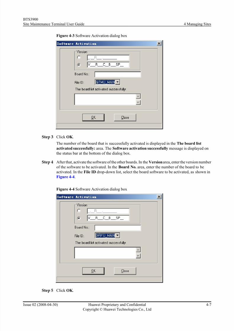
Figure 4-3 Software Activation dialog box
Step 3 Click OK .
The number of the board that is successfully activated is displayed in the The board list
activated successfully: area. The Software activation successfully message is displayed on
the status bar at the bottom of the dialog box.
Step 4 After that, activate the software of the other boards. In the Version area, enter the version number
of the software to be activated. In the Board No. area, enter the number of the board to be
activated. In the File ID drop-down list, select the board software to be activated, as shown inFigure 4-4.
Figure 4-4 Software Activation dialog box
Step 5 Click OK .
BTS3900
Site Maintenance Terminal User Guide 4 Managing Sites
Issue 02 (2008-04-30) Huawei Proprietary and Confidential
Copyright © Huawei Technologies Co., Ltd
4-7
8/10/2019 BTS3900 Site Maintenance Terminal User Guide-(V300R008_02)
http://slidepdf.com/reader/full/bts3900-site-maintenance-terminal-user-guide-v300r00802 38/147

8/10/2019 BTS3900 Site Maintenance Terminal User Guide-(V300R008_02)
http://slidepdf.com/reader/full/bts3900-site-maintenance-terminal-user-guide-v300r00802 39/147
Procedure
Step 1 In the left pane of the Site Maintenance Terminal System window, click Site. In the right pane
of the window, double-click Site Reset Hierarchically.
The Site Reset Hierarchically dialog box is displayed.
Step 2 In the Reset Level area, select a reset level. In the Reset Port area, select a port, as shown in
Figure 4-5.
Figure 4-5 Site Reset Hierarchically dialog box
Step 3 Click OK .
----End
4.5 Monitoring Environment
This function is performed to monitor and manage the environment parameters in a site. By
performing this function, you can view the current temperature and humidity and set the
temperature and humidity thresholds. The BTS can run normally in a safe and suitable site
environment. You can also clear a burglar alarm or a smoke alarm and disable an EAC alarm.
Prerequisite
You have logged in to the BTS through the Site Maintenance Terminal.
Context
Table 4-4 describes the parameters.
BTS3900
Site Maintenance Terminal User Guide 4 Managing Sites
Issue 02 (2008-04-30) Huawei Proprietary and Confidential
Copyright © Huawei Technologies Co., Ltd
4-9

8/10/2019 BTS3900 Site Maintenance Terminal User Guide-(V300R008_02)
http://slidepdf.com/reader/full/bts3900-site-maintenance-terminal-user-guide-v300r00802 40/147
Table 4-4 Parameters in the Environment Monitor dialog box
Parameter Meaning ValueRange
Clear RobberyAlarm
Clearing the infrared alarm and the door status alarm -
Set Temperature
and Humidity
Threshold
Set the upper and lower thresholds of temperature and
humidity. Based on the thresholds, the alarm box reports
a temperature alarm and a humidity alarm.
-
Relay Operation Control the relay status. The relay is used to start or close
the refrigeration device, heating device, dehumidifier,
humidifier, fire extinguisher, and anti-burglar device.
The default state is Close.
-
Disable the EAC
Alarm
Disable the reporting of alarms in a short time. In the
maintenance of equipment, the related personnel canselect the option to disable the reporting of alarms for
ten minutes. After ten minutes, the alarms can be
reported. If the equipment is maintained for more than
10 minutes, restart the alarm shield.
-
Get Current
Temperature and
Humidity
View the temperature and humidity associated with the
base station in operation. This parameter can be used for
querying the status of the environment alarm.
-
Clear Smoke
Alarm
Clearing the smoke alarm -
Procedure
Step 1 In the left pane of the Site Maintenance Terminal System window, click Site . In the right
pane of the window, double-click Environment Monitor.
The Environment Monitor dialog box is displayed, as shown in Figure 4-6.
4 Managing Sites
BTS3900
Site Maintenance Terminal User Guide
4-10 Huawei Proprietary and Confidential
Copyright © Huawei Technologies Co., Ltd
Issue 02 (2008-04-30)

8/10/2019 BTS3900 Site Maintenance Terminal User Guide-(V300R008_02)
http://slidepdf.com/reader/full/bts3900-site-maintenance-terminal-user-guide-v300r00802 41/147
Figure 4-6 Environment Monitor dialog box
Step 2 Perform the following operations in the Select Operation Type area:
Select... Then...
Clear Robbery Alarm Go to Step 3.
Set Temperature and Humidity Threshold In the Temperature and Humidity
Threshold area, set the thresholds. Then, go to
Step 3.
Relay Operation In the Relay Operation area, set the related
options to start or stop the equipment. Then, go
to Step 3.
Disable the EAC Alarm Go to Step 3.
Get Current Temperature and Humidity Go to Step 3.
Clear Smoke Alarm Go to Step 3.
Step 3 Click OK .
----End
4.6 Testing Transport Performance
This function is performed to check whether the transmission link is normal through an E1loopback test and a timeslot loopback test.
BTS3900
Site Maintenance Terminal User Guide 4 Managing Sites
Issue 02 (2008-04-30) Huawei Proprietary and Confidential
Copyright © Huawei Technologies Co., Ltd
4-11

8/10/2019 BTS3900 Site Maintenance Terminal User Guide-(V300R008_02)
http://slidepdf.com/reader/full/bts3900-site-maintenance-terminal-user-guide-v300r00802 42/147
Prerequisite
You have logged in to the BTS through the Site Maintenance Terminal.
Context
Table 4-5 describes the parameters.
Table 4-5 Parameters in the Transport Performance Test dialog box
Parameter Meaning Value Range
Select TMU You can select a TMU based on a test object. Active TMU,
Master/Backup
TMU, Slave
TMU1, and
Slave TMU2
Port No. This specifies the port to which the E1 cable is
connected.
Port 0-port 7
Test duration This specify the duration of a specific loopback mode. Recommended
value:
multiples of 10
minutes
(default value:
one minute)
E1 Loopback During an E1 loopback test, the OML is broken.
You can stop the loopback test ahead of time byresetting the BTS. After the test is complete, the
system automatically releases the loop and resets the
BTS.
All the 32
timeslots (0-31)
are tested by
default.
Timeslot
Loopback
Only one timeslot can be tested once. The timeslot
carrying the OML cannot be tested. In addition, only
port 0 and port 1 on each DTMU can be tested. During
a timeslot loopback test, the tested timeslot is
unusable. After the test is complete, the BTS will not
be reset.
You can stop the loopback test ahead of time by
clicking Stop. After the test is complete, the systemautomatically releases the loop and the tested timeslot
becomes usable. You can click Stop to stop the test
or wait for the completion of the test duration. The
timeslot in the self-loop test is normal again.
-
Procedure
Step 1 In the left pane of the Site Maintenance Terminal System window, click Site. In the right pane
of the window, double-click Transport Performance Test.
The Transport Performance Test dialog box is displayed.
4 Managing Sites
BTS3900
Site Maintenance Terminal User Guide
4-12 Huawei Proprietary and Confidential
Copyright © Huawei Technologies Co., Ltd
Issue 02 (2008-04-30)

8/10/2019 BTS3900 Site Maintenance Terminal User Guide-(V300R008_02)
http://slidepdf.com/reader/full/bts3900-site-maintenance-terminal-user-guide-v300r00802 43/147
Step 2 In the Select TMU area, select a TMU. In the Port No. area, select a port number. In the Loop-
back Mode area, select a loopback mode. In the Test Duration area, enter the test duration.
Step 3 Click Start.
The Warning dialog box is displayed.
Step 4 Click OK . The result is displayed on the status bar, as shown in Figure 4-7.
Figure 4-7 Transport Performance Test dialog box
----End
4.7 Querying Alarm Delay Time
This function is performed to query the alarm delay time of boards.
Prerequisite
You have logged in to the BTS through the Site Maintenance Terminal.
Context
Some alarms that do not affect services are reported frequently in a short time, and then disappear
quickly. Therefore, many alarms are generated while the fault alarms are not detected in time.
By setting an appropriate alarm delay time, some alarms that are generated and cleared frequently
in a short time can be prevented from being reported in a large quantity.
BTS3900
Site Maintenance Terminal User Guide 4 Managing Sites
Issue 02 (2008-04-30) Huawei Proprietary and Confidential
Copyright © Huawei Technologies Co., Ltd
4-13

8/10/2019 BTS3900 Site Maintenance Terminal User Guide-(V300R008_02)
http://slidepdf.com/reader/full/bts3900-site-maintenance-terminal-user-guide-v300r00802 44/147
Procedure
Step 1 In the left pane of the Site Maintenance Terminal System window, click Site. In the right pane
of the window, double-click Site Alarm Delay Time Query.
The Query Warn Delay Time dialog box is displayed.
Step 2 Click Query. The result is displayed in the Query Warn Delay Time dialog box, as shown in
Figure 4-8.
Figure 4-8 Query Warn Delay Time dialog box
NOTE
You can set a specific alarm delay time through the LMT on the BSC side.
----End
4.8 Testing the RF Specifications
This describes how to test the RF specifications. The specifications of the receiver involve the
receiver sensitivity, GSM static L1 (first level) function, and the block test. The specifications
of the transmitter involve modulation spectrum, handover spectrum, modulation accuracy, and
spurious emission.
Prerequisite
l You have logged in to the BTS through the Site Maintenance Terminal.
4 Managing Sites
BTS3900
Site Maintenance Terminal User Guide
4-14 Huawei Proprietary and Confidential
Copyright © Huawei Technologies Co., Ltd
Issue 02 (2008-04-30)

8/10/2019 BTS3900 Site Maintenance Terminal User Guide-(V300R008_02)
http://slidepdf.com/reader/full/bts3900-site-maintenance-terminal-user-guide-v300r00802 45/147
l The test device (for example, a base station integrated tester) is connected to the ANT port
on the DRFU.
Context
A base station integrated tester is required to test the RF specifications. Pay attention to thefollowing points before the test:
l Before the test, you need to reset the configured RC by clicking User-defined Message.
– If the E1 cables are connected, after the configured RC is reset, you can observe the
RUN LED on the DRFU to check whether the RC is running normally. If the RC is
running normally, you can perform the test.
– If the E1 cables are not connected, and if the LAPD alarm is displayed on the status bar
after the configured RC is reset, you can infer that the RC is running normally. Then,
you can perform the test.
l In the Frequency Hopping Mode drop-down list, choose Baseband hopping or RF
hopping. Click Frequency hopping setup to specify the frequency hopping parameters.l When testing the specifications of the transmitter, you can choose the modulation mode of
the channel by clicking Channel Modulation.
l Based on the configuration mode between the DRFUs on the BTS, you can choose
Mode, Transmitter Channel, or Receiver Channel in the DTRU Channel Setup dialog
box.
Procedure
Step 1 In the left pane of the Site Maintenance Terminal System window, select Site. In the right
pane of the window, double-click RF Specification Test.
The Warning dialog box is displayed.
Step 2 Click OK .
The RF Specification Test window is displayed, as shown in Figure 4-9.
BTS3900
Site Maintenance Terminal User Guide 4 Managing Sites
Issue 02 (2008-04-30) Huawei Proprietary and Confidential
Copyright © Huawei Technologies Co., Ltd
4-15

8/10/2019 BTS3900 Site Maintenance Terminal User Guide-(V300R008_02)
http://slidepdf.com/reader/full/bts3900-site-maintenance-terminal-user-guide-v300r00802 46/147
Figure 4-9 RF Specification Test window
Step 3 Choose DRFU. In the Channel type area, specify the Cell No. and RC No., and then click
User-defined Message.
l If the E1 cables are connected, you can observe the RUN LED on the DRFU to check whether
the RC runs normally. If the RC runs normally, you can perform the test.
l If the E1 cables are not connected and if the LAPD alarm is displayed on the status bar, you
can infer that the DTRU runs normally.
Step 4 In the Test Item area, click Transmitter or Receiver, and choose the test item for the transmitter
or receiver.
l If the Transmitter option is selected, you can specify the modulation mode of the channel
by clicking Channel Modulation.
l If the Receiver option is selected, you need not set Channel Modulation.
Step 5 Choose another item to be tested.
l If you choose No frequency hopping from the Frequency Hopping Mode drop-down
list, you need not set the Frequency hopping setup.l In the Frequency Hopping Mode drop-down list, choose Baseband hopping or RF
hopping. Click Frequency hopping setup to specify the frequency hopping parameters.
Step 6 Click Start Test.
The result is displayed on the test device.
----End
4.9 Querying the Ring Topology Parameters
This function is performed to query the ring topology parameters, including the workingdirection of a site in the ring topology (Port 0 is forward link and port 1 is reverse link) and the
4 Managing Sites
BTS3900
Site Maintenance Terminal User Guide
4-16 Huawei Proprietary and Confidential
Copyright © Huawei Technologies Co., Ltd
Issue 02 (2008-04-30)

8/10/2019 BTS3900 Site Maintenance Terminal User Guide-(V300R008_02)
http://slidepdf.com/reader/full/bts3900-site-maintenance-terminal-user-guide-v300r00802 47/147
indication of auto rotate in the ring topology. If automatic rotation is permitted, the result also
involves the waiting time before rotation and the scheduled time for attempts before rotation.
Prerequisite
You have logged in to the BTS through the Site Maintenance Terminal.
Context
If the result is Auto Rotate Permission, the working direction of the site in ring topology can
be automatically rotated. The system displays the Waiting Time Before Rotate area and the
Try Rotating Duration Time area. The data is configured through the Data Configuration
System on the BSC side.
If the result is Auto Rotate Not Permitted, the working direction of the site in ring topology is
unchanged. At this moment, the Waiting Time Before Rotate and the Try Rotating Duration
Time are insignificant. The displayed time is 65535 seconds.
Procedure
In the left pane of the Site Maintenance Terminal System window, click Site. In the right pane
of the window, double-click Ring Topology Parameter Query.
The Ring Topology Parameter Query dialog box is displayed, as shown in Figure 4-10.
Figure 4-10 Ring Topology Parameter Query dialog box
NOTE
If the dialog box is open for some time, click Query to refresh the querying result.
----End
4.10 Viewing the Bar Codes
This describes how to view the bar codes of the boards configured in the currently connectedBTS.
BTS3900
Site Maintenance Terminal User Guide 4 Managing Sites
Issue 02 (2008-04-30) Huawei Proprietary and Confidential
Copyright © Huawei Technologies Co., Ltd
4-17

8/10/2019 BTS3900 Site Maintenance Terminal User Guide-(V300R008_02)
http://slidepdf.com/reader/full/bts3900-site-maintenance-terminal-user-guide-v300r00802 48/147
Prerequisite
You have logged in to the BTS through the Site Maintenance Terminal.
ContextThe bar code is the basic information of the board and is used to identify the manufacturing
information of the board. When several faulty boards are found with the same bar code, trace
other boards produced in the same batch through the bar codes to see whether they are faulty.
Through the Local Maintenance Terminal, you can view the bar codes of the boards in all the
BTSs under the BSC. Through the Site Maintenance Terminal System, you can view the bar
codes of the boards in the connected BTS.
l The bar code is represented in ASCII code.
l You can view only the bar code of the board that is already configured.
l The boards that support bar code reporting are the GTMU, the DRFU, the BFU, the PEU,
and the DEMU.
Procedure
In the left pane of the Site Maintenance Terminal System window, select Site. In the right
pane of the window, double-click Bar Code Query.
The Bar Code Query dialog box is displayed, as shown in Figure 4-11.
Figure 4-11 Bar Code Query dialog box
NOTE
If the dialog box has been open for a while, click Start to refresh the dialog box.
----End
4 Managing Sites
BTS3900
Site Maintenance Terminal User Guide
4-18 Huawei Proprietary and Confidential
Copyright © Huawei Technologies Co., Ltd
Issue 02 (2008-04-30)

8/10/2019 BTS3900 Site Maintenance Terminal User Guide-(V300R008_02)
http://slidepdf.com/reader/full/bts3900-site-maintenance-terminal-user-guide-v300r00802 49/147
4.11 Managing the Site Board Parameters
This function is performed to view the parameters associated with the boards configured in a
site.
Prerequisite
You have logged in to the BTS through the Site Maintenance Terminal.
Procedure
Step 1 In the left pane of the Site Maintenance Terminal System window, click Site. In the right pane
of the window, double-click Site Board Parameter Management.
The Site Board Parameter Management dialog box is displayed, as shown in Figure 4-12.
Figure 4-12 Site Board Parameter Management dialog box
Step 2 Click Query to query the board parameters of the BTS.
The result is displayed in the parameter area, as shown in Figure 4-13.
BTS3900
Site Maintenance Terminal User Guide 4 Managing Sites
Issue 02 (2008-04-30) Huawei Proprietary and Confidential
Copyright © Huawei Technologies Co., Ltd
4-19

8/10/2019 BTS3900 Site Maintenance Terminal User Guide-(V300R008_02)
http://slidepdf.com/reader/full/bts3900-site-maintenance-terminal-user-guide-v300r00802 50/147
Figure 4-13 Site Board Parameter Management dialog box
----End
4.12 Testing the E1 BER
You can get the information about the link transmission quality of the E1 port in real time by
monitoring the E1 BER.
Prerequisite
l You have logged in to the BTS through the Site Maintenance Terminal.
l On the Local Maintenance Terminal, the BTS attribute is set to Support CRC4 Check.
Context
The bit error rate is defined as follows:
l Bit Error Rate (BER): number of error bits per unit time
l Unit Time: interval that the interface board samples the error bits
l Remain Time: remaining time of the bit error rate test. When the remaining time is 0, the
test ends.
l Total Error: total number of error bits
l Unit Error: number of error bits detected in a unit time
l Total Error Overflow: The number of error bits exceeds a predefined threshold.
Procedure
Step 1 In the left pane of the Site Maintenance Terminal System window, click Site. In the right pane
of the window, double-click E1 BET Test.
The E1 BER Test dialog box is displayed.
4 Managing Sites
BTS3900
Site Maintenance Terminal User Guide
4-20 Huawei Proprietary and Confidential
Copyright © Huawei Technologies Co., Ltd
Issue 02 (2008-04-30)

8/10/2019 BTS3900 Site Maintenance Terminal User Guide-(V300R008_02)
http://slidepdf.com/reader/full/bts3900-site-maintenance-terminal-user-guide-v300r00802 51/147
Step 2 In the Parameters area, set TMU Port No. and Test Duration, and then click Start Test. The
test result is displayed in the Test Result area, as shown in Figure 4-14.
Figure 4-14 E1 BER Test dialog box
Step 3 Click Stop Test to end the E1 BER test.
----End
4.13 Managing the RET AntennaThis function is performed to query and set parameters of the RET antenna connected to the
BTS.
Prerequisite
l You have logged in to the BTS through the Site Maintenance Terminal.
l The RF unit is connected to the RET antenna.
Procedure
Step 1 In the left pane of the Site Maintenance Terminal System window, click Site. In the right paneof the window, double-click RET Antenna Manage.
The RET Antenna Manage dialog box is displayed, as shown in Figure 4-15.
Step 2 Click Query. The query result is displayed in the RET Antenna Information area.
BTS3900
Site Maintenance Terminal User Guide 4 Managing Sites
Issue 02 (2008-04-30) Huawei Proprietary and Confidential
Copyright © Huawei Technologies Co., Ltd
4-21

8/10/2019 BTS3900 Site Maintenance Terminal User Guide-(V300R008_02)
http://slidepdf.com/reader/full/bts3900-site-maintenance-terminal-user-guide-v300r00802 52/147
Figure 4-15 RET Antenna Manage dialog box
Step 3 In the RET Antenna Configuration area, click the Set Tilt Angle tab, set RET Antenna Tilt
Angle, and then click Set. The result is displayed in the Operation Status area.
NOTE
The tilt angle must be in the range displayed in the RET Antenna Information area. Otherwise, the setting
does not take effect.
Step 4 In the RET Antenna Setting area, click the Load Configuration File tab. In the Select File
area, click Browse and select the configuration file to be loaded. Then, click Set. The result is
displayed in the Operation Status area.
Step 5 In the RET Antenna Setting area, click the Other Operations tab. Select the antenna to be
operated in the Select Antenna Operation area, and then click Set. The result is displayed in
the Operation Status area.
----End
4 Managing Sites
BTS3900
Site Maintenance Terminal User Guide
4-22 Huawei Proprietary and Confidential
Copyright © Huawei Technologies Co., Ltd
Issue 02 (2008-04-30)

8/10/2019 BTS3900 Site Maintenance Terminal User Guide-(V300R008_02)
http://slidepdf.com/reader/full/bts3900-site-maintenance-terminal-user-guide-v300r00802 53/147
5 Managing Cells
About This Chapter
The cell management involves managing cell attributes and cell extended attributes, testing all
the BTs and RCs of a cell so that they can be locked or unlocked, and checking whether the BTs
and RCs are functional.
5.1 Managing Cell Attributes
This function is performed to view or set the interference level boundary, interference average
parameter, connection failure threshold, T200, overload period, starting frame No., CCCH load
threshold, CCCH load indicating period, RACH busy determination threshold, RACH load
averaging slots, BTS air timer, NY1, BSIC, BCCH ARFCN, and Max. time advance.
5.2 Managing Cell Extended Attributes
This function is performed to view or set the RF resource indication period, paging times, and
access error threshold.
5.3 Changing the Cell Management State
This function is performed to lock or unlock the BTs and RCs of a cell.
5.4 Performing the Cell Performance Test
This function is performed to test all the RCs of a cell and to check whether they are functional.
BTS3900
Site Maintenance Terminal User Guide 5 Managing Cells
Issue 02 (2008-04-30) Huawei Proprietary and Confidential
Copyright © Huawei Technologies Co., Ltd
5-1

8/10/2019 BTS3900 Site Maintenance Terminal User Guide-(V300R008_02)
http://slidepdf.com/reader/full/bts3900-site-maintenance-terminal-user-guide-v300r00802 54/147

8/10/2019 BTS3900 Site Maintenance Terminal User Guide-(V300R008_02)
http://slidepdf.com/reader/full/bts3900-site-maintenance-terminal-user-guide-v300r00802 55/147
Parameter Meaning ValueRange
T200 Determines the timer duration for responses after
messages are sent in the related channels.
0-1275
(SDCCH,
full rate
FACCH, half
rate FACCH,
SDCCH/
SAPI3) and
0–2550 (for
SACCH/
TCH/SPAI0,
SACCH/
SDCCH,
SACCH/
TCH/SAPI3)
Max. time
advance
Time advance for the farthest point of the area that the
cell covers
0–127 (63 is
recommende
d.)
Overload period The BTS calculates the channel usage at a fixed interval
to check whether the channel is overloaded. The interval
is determined by the overloading period.
-
CCCH load
threshold
Ratio of times of successful random access to total
collision times within the time.
0-100%
(80% is
recommende
d.)
CCCH load
indicating period
Determines the duration within which the BTS must
report the load on the CCCH to the MSC.
0-255 (15 is
recommende
d.)
RACH busy
determination
threshold
Determines the level threshold of random access. -255 dBm
through 0
dBm
RACH load
averaging slots
Measuring the average loading timeslot number for
random access channel.
-
Cell air-interfacetimer
Determines the timing length. 0-2550
NY1 The maximum number of times physical information
can be resent. It is related to handover.
0-255 (6 or 4
is
recommende
d.)
BTS3900
Site Maintenance Terminal User Guide 5 Managing Cells
Issue 02 (2008-04-30) Huawei Proprietary and Confidential
Copyright © Huawei Technologies Co., Ltd
5-3

8/10/2019 BTS3900 Site Maintenance Terminal User Guide-(V300R008_02)
http://slidepdf.com/reader/full/bts3900-site-maintenance-terminal-user-guide-v300r00802 56/147
Parameter Meaning ValueRange
BCCH ARFCN Determines the number of the BCCH frequency. There
are 124, 193, 374, and 299 frequencies on the 850 MHz,
900 MHz, 1800 MHz, and 1900 MHz bands
respectively.
128-251 (850
MHz); 1–
124, 966–
1023 (900
MHz); 512–
885 (1800
MHz); 512–
810 (1900
MHz)
BSIC The base station identity code (Base station identity
code = network color code + base station color code)
0-63
Starting frame No. This parameter determines the frame from which the
setting takes effect.
0-42431
Frame offset The variance in the number of configured frames for
different cells under one BTS.
0-7
Procedure
Step 1 In the left pane of the Site Maintenance Terminal System window, click Cell. In the right pane
of the window, double-click Cell Attributes Management.
The Cell Attributes Management dialog box is displayed, as shown in Figure 5-1.
Figure 5-1 Cell Attributes Management dialog box
Step 2 Enter different values for each attribute.
5 Managing Cells
BTS3900
Site Maintenance Terminal User Guide
5-4 Huawei Proprietary and Confidential
Copyright © Huawei Technologies Co., Ltd
Issue 02 (2008-04-30)

8/10/2019 BTS3900 Site Maintenance Terminal User Guide-(V300R008_02)
http://slidepdf.com/reader/full/bts3900-site-maintenance-terminal-user-guide-v300r00802 57/147
NOTE
The parameters displayed on the terminal are the activated parameters on the BTS. You can adjust their
values.
Step 3 Click Set.
The attributes are set successfully. The result is displayed on the status bar at the bottom of the
Cell Attributes Management dialog box.
Step 4 Click Refresh.
The attributes are obtained successfully. The result is displayed on the status bar at the bottom
of the Cell Attributes Management dialog box, as shown in Figure 5-1.
NOTE
The configure operation enables the site maintenance terminal to activate the parameters on the BTS. The
refresh operation enables the site maintenance terminal to obtain the latest data from the BTS. You can
perform the refresh operation to confirm the accuracy of data.
----End
5.2 Managing Cell Extended Attributes
This function is performed to view or set the RF resource indication period, paging times, and
access error threshold.
Prerequisite
You have logged in to the BTS through the Site Maintenance Terminal.
ContextTable 5-2 describes the parameters.
Table 5-2 Parameters in the Cell Extended Attributes Management dialog box
Parameter Meaning ValueRange
RF resource
indication period
Interval at which the BTS reports the RF resources to
the MSC
1-31
Paging times This parameter is used for the BTS to determine whether
a paging message is resent. The paging times configuredin the BTS and that configured in the MSC together
control the retransmission times of the paging message.
The total paging times is approximately equivalent to
the multiplication of the configuration in the BTS with
the configuration in the MSC.
0-4
BTS3900
Site Maintenance Terminal User Guide 5 Managing Cells
Issue 02 (2008-04-30) Huawei Proprietary and Confidential
Copyright © Huawei Technologies Co., Ltd
5-5
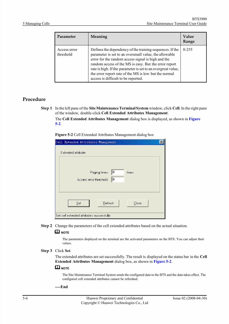
8/10/2019 BTS3900 Site Maintenance Terminal User Guide-(V300R008_02)
http://slidepdf.com/reader/full/bts3900-site-maintenance-terminal-user-guide-v300r00802 58/147

8/10/2019 BTS3900 Site Maintenance Terminal User Guide-(V300R008_02)
http://slidepdf.com/reader/full/bts3900-site-maintenance-terminal-user-guide-v300r00802 59/147
5.3 Changing the Cell Management State
This function is performed to lock or unlock the BTs and RCs of a cell.
Prerequisite
You have logged in to the BTS through the Site Maintenance Terminal.
Context
CAUTION
When the cell management state is changed to Locked, all the channels in the cell are in the Outof Service state. That is, the cell cannot provide any service when it is locked. Therefore, you
should perform this function with care.
Procedure
Step 1 In the left pane of the Site Maintenance Terminal System window, click Cell. In the right pane
of the window, double-click Change Cell Management State.
The Change Cell Management State dialog box is displayed, as shown in Figure 5-3.
Figure 5-3 Change Cell Management State dialog box
Step 2 Select the management state you need.
NOTE
The parameters displayed on the terminal are the activated parameters on the BTS. You can adjust their
values.
Step 3 Click OK .
The cell management state is changed successfully. The result is displayed on the status bar at
the bottom of the Change Cell Management State dialog box, as shown in Figure 5-3.
----End
BTS3900
Site Maintenance Terminal User Guide 5 Managing Cells
Issue 02 (2008-04-30) Huawei Proprietary and Confidential
Copyright © Huawei Technologies Co., Ltd
5-7

8/10/2019 BTS3900 Site Maintenance Terminal User Guide-(V300R008_02)
http://slidepdf.com/reader/full/bts3900-site-maintenance-terminal-user-guide-v300r00802 60/147
5.4 Performing the Cell Performance Test
This function is performed to test all the RCs of a cell and to check whether they are functional.
Prerequisite
You have logged in to the BTS through the Site Maintenance Terminal.
Procedure
Step 1 In the left pane of the Site Maintenance Terminal System window, click Cell. In the right pane
of the window, double-click Cell Performance Test.
The Site Test dialog box is displayed, as shown in Figure 5-4.
Figure 5-4 Cell Test dialog box
Step 2 Click Start.
The test report is obtained. The result is displayed in the Cell Test dialog box. If the test is
successful, you can infer that the BTs and the RCs are functional, as shown in Figure 5-4.
NOTE
During the test, you can click Stop to end the test. The result is displayed in the Cell Test dialog box.
----End
5 Managing Cells
BTS3900
Site Maintenance Terminal User Guide
5-8 Huawei Proprietary and Confidential
Copyright © Huawei Technologies Co., Ltd
Issue 02 (2008-04-30)

8/10/2019 BTS3900 Site Maintenance Terminal User Guide-(V300R008_02)
http://slidepdf.com/reader/full/bts3900-site-maintenance-terminal-user-guide-v300r00802 61/147
6 Managing BTs
About This Chapter
The BT management involves locking or unlocking a BT, resetting a BT, performing the RC
self-test, view the status of the channels on a specified BT, and enabling a specified RC to
transmit signals at a predefined power level.
6.1 Changing the BT Management State
This function is performed to lock or unlock a BT.
6.2 Re-Initializing a BT
This function is performed to reset a BT and to reload the configuration data of the BT.
6.3 Performing BT Tests
The BT tests involve the BIU loopback test and the TRX self-test. The BIU loopback test is
performed to check the connection between the BT of the specified TRX and the physical links
of the Abis signaling channel. The TR X self-test is performed to check RCs and report the test
result.
6.4 Viewing the Channel Status
This function is performed to query the status of all the channels on a BT.
6.5 Setting the TRX Full Power Emission
This function is performed to enable a specified TRX to perform the full power emission and to
test the transmit power level of signals. Based on this level, the software and hardware parameters
can be adjusted accordingly during network planning. Therefore, the coverage of the BTS can
be optimized.
BTS3900
Site Maintenance Terminal User Guide 6 Managing BTs
Issue 02 (2008-04-30) Huawei Proprietary and Confidential
Copyright © Huawei Technologies Co., Ltd
6-1

8/10/2019 BTS3900 Site Maintenance Terminal User Guide-(V300R008_02)
http://slidepdf.com/reader/full/bts3900-site-maintenance-terminal-user-guide-v300r00802 62/147

8/10/2019 BTS3900 Site Maintenance Terminal User Guide-(V300R008_02)
http://slidepdf.com/reader/full/bts3900-site-maintenance-terminal-user-guide-v300r00802 63/147
The BT management state is changed successfully. The result is displayed in the Operational
result pane, as shown in Figure 6-1.
NOTE
You can click the Operational result pane to have it enlarged. The detailed information can be displayed
in the pane. You can click in the enlarged pane to have the pane return to the original state.
----End
6.2 Re-Initializing a BT
This function is performed to reset a BT and to reload the configuration data of the BT.
Prerequisite
You have logged in to the BTS through the Site Maintenance Terminal.
Context
CAUTION
Re-initializing BT is actually the hard reset of the BT. All the services of the BT are interrupted
during the hard reset. Therefore, you should perform this function carefully.
Procedure
Step 1 In the left pane of the Site Maintenance Terminal System window, click BT. In the right pane
of the window, double-click BT Reinitialization.
The BT Reinitialization dialog box is displayed, as shown in Figure 6-2.
Figure 6-2 BT Reinitialization dialog box
Step 2 Click OK .
The result is displayed in the BT Reinitialization dialog box, as shown in Figure 6-2.
----End
BTS3900
Site Maintenance Terminal User Guide 6 Managing BTs
Issue 02 (2008-04-30) Huawei Proprietary and Confidential
Copyright © Huawei Technologies Co., Ltd
6-3
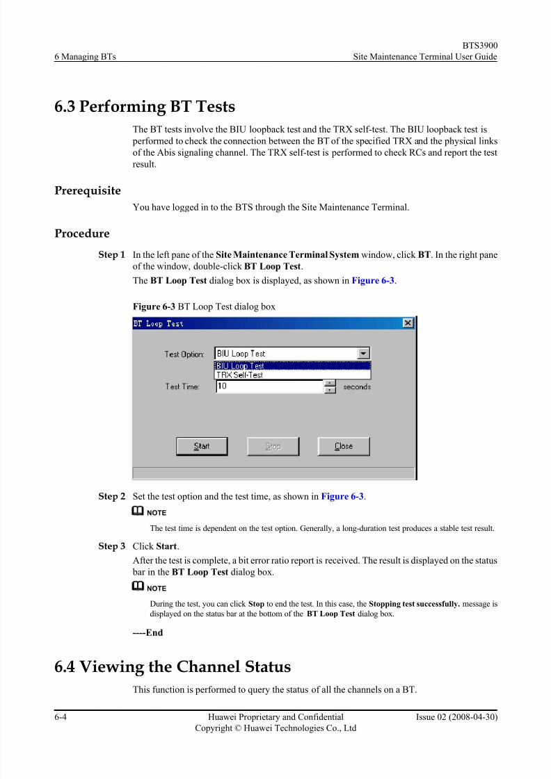
8/10/2019 BTS3900 Site Maintenance Terminal User Guide-(V300R008_02)
http://slidepdf.com/reader/full/bts3900-site-maintenance-terminal-user-guide-v300r00802 64/147
6.3 Performing BT Tests
The BT tests involve the BIU loopback test and the TRX self-test. The BIU loopback test is
performed to check the connection between the BT of the specified TRX and the physical links
of the Abis signaling channel. The TRX self-test is performed to check RCs and report the test
result.
Prerequisite
You have logged in to the BTS through the Site Maintenance Terminal.
Procedure
Step 1 In the left pane of the Site Maintenance Terminal System window, click BT. In the right pane
of the window, double-click BT Loop Test.
The BT Loop Test dialog box is displayed, as shown in Figure 6-3.
Figure 6-3 BT Loop Test dialog box
Step 2 Set the test option and the test time, as shown in Figure 6-3.
NOTE
The test time is dependent on the test option. Generally, a long-duration test produces a stable test result.
Step 3 Click Start.After the test is complete, a bit error ratio report is received. The result is displayed on the status
bar in the BT Loop Test dialog box.
NOTE
During the test, you can click Stop to end the test. In this case, the Stopping test successfully. message is
displayed on the status bar at the bottom of the BT Loop Test dialog box.
----End
6.4 Viewing the Channel Status
This function is performed to query the status of all the channels on a BT.
6 Managing BTs
BTS3900
Site Maintenance Terminal User Guide
6-4 Huawei Proprietary and Confidential
Copyright © Huawei Technologies Co., Ltd
Issue 02 (2008-04-30)

8/10/2019 BTS3900 Site Maintenance Terminal User Guide-(V300R008_02)
http://slidepdf.com/reader/full/bts3900-site-maintenance-terminal-user-guide-v300r00802 65/147
Prerequisite
You have logged in to the BTS through the Site Maintenance Terminal.
ContextA channel can be in any of the following states: A (Active), I (Idle), O (Out of Service), B
(Blocked), and U (Unavailable). A channel in the O, B, or U state cannot be seized by a call.
Procedure
In the left pane of the Site Maintenance Terminal System window, click BT. In the right pane
of the window, double-click View Channel State.
The View Channel State dialog box is displayed, as shown in Figure 6-4.
Figure 6-4 View Channel State dialog box
----End
6.5 Setting the TRX Full Power Emission
This function is performed to enable a specified TRX to perform the full power emission and totest the transmit power level of signals. Based on this level, the software and hardware parameters
can be adjusted accordingly during network planning. Therefore, the coverage of the BTS can
be optimized.
Prerequisite
l You have logged in to the BTS through the Site Maintenance Terminal.
l The power test devices are prepared.
Context
The static power level ranges from 0-10 dBm in steps of 2 dBm.
BTS3900
Site Maintenance Terminal User Guide 6 Managing BTs
Issue 02 (2008-04-30) Huawei Proprietary and Confidential
Copyright © Huawei Technologies Co., Ltd
6-5
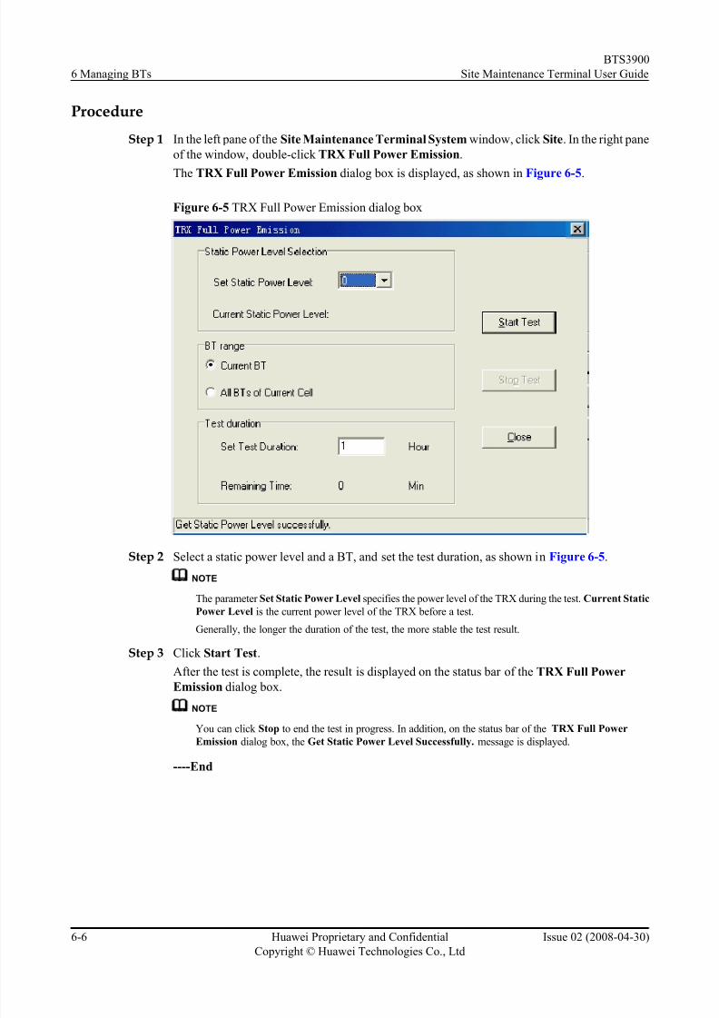
8/10/2019 BTS3900 Site Maintenance Terminal User Guide-(V300R008_02)
http://slidepdf.com/reader/full/bts3900-site-maintenance-terminal-user-guide-v300r00802 66/147

8/10/2019 BTS3900 Site Maintenance Terminal User Guide-(V300R008_02)
http://slidepdf.com/reader/full/bts3900-site-maintenance-terminal-user-guide-v300r00802 67/147
7 Managing RCs
About This Chapter
The RC management involves setting the attributes and extended attributes of an RC, locking
or unlocking an RC, resetting an RC, and adjusting power of an RC automatically.
7.1 Managing RC Attributes
This function is performed to view and set the Absolute Radio Frequency Channel Number
(ARFCN), that is, the frequency number of the current RC.
7.2 Managing RC Extended Attributes
This function is performed to view or set the extended RC attributes, including the static power
level, saturation threshold, saturation voltage threshold, and power mode.
7.3 Changing the RC Management State
This function is performed to lock or unlock an RC.
7.4 Re-Initializing an RC
This function is performed to reset an RC. After the RC is reset, the GTMU sends the stored
configuration data to the RC again, and the configuration data takes effect on the RC.
7.5 Obtaining the RC Power Mode
This function is performed to view the power type and the current work mode of an RC.
7.6 Obtaining the Auto Power Adjustment Type
This function is performed to obtain the information about the frequency band of an RC andwhether the RC supports the automatic power control function.
BTS3900
Site Maintenance Terminal User Guide 7 Managing RCs
Issue 02 (2008-04-30) Huawei Proprietary and Confidential
Copyright © Huawei Technologies Co., Ltd
7-1

8/10/2019 BTS3900 Site Maintenance Terminal User Guide-(V300R008_02)
http://slidepdf.com/reader/full/bts3900-site-maintenance-terminal-user-guide-v300r00802 68/147
7.1 Managing RC Attributes
This function is performed to view and set the Absolute Radio Frequency Channel Number
(ARFCN), that is, the frequency number of the current RC.
Prerequisite
You have logged in to the BTS through the Site Maintenance Terminal
Context
Table 7-1 describes the parameters.
Table 7-1 Parameters in the RC Attributes Management dialog box
Parameter Meaning Value Range
ARFCN This parameter specifies the
frequency number of an RC.
l 850 MHz: 124 frequencies numbered
from 128 to 251
l 900 MHz: 193 frequencies numbered
from 1 to 124 and 955 to 1023
l 1800 MHz: 374 frequencies numbered
from 512 to 885
l 1900 MHz: 299 frequencies numbered
from 512 to 810
Procedure
Step 1 In the left pane of the Site Maintenance Terminal System window, click RC. In the right pane
of the window, double-click RC Attributes Management.
The RC Attributes Management dialog box is displayed, as shown in Figure 7-1.
7 Managing RCs
BTS3900
Site Maintenance Terminal User Guide
7-2 Huawei Proprietary and Confidential
Copyright © Huawei Technologies Co., Ltd
Issue 02 (2008-04-30)

8/10/2019 BTS3900 Site Maintenance Terminal User Guide-(V300R008_02)
http://slidepdf.com/reader/full/bts3900-site-maintenance-terminal-user-guide-v300r00802 69/147
Figure 7-1 RC Attributes Management dialog box
Step 2 Set ARFCN.
NOTE
The parameters displayed on the terminal are the activated parameters on the BTS. You can adjust their
values.
Step 3 Click Set.
The RC attributes are set successfully. The result is displayed on the status bar in the RC
Attributes Management dialog box.
Step 4 Click Refresh.
The RC attributes are obtained successfully. The result is displayed on the status bar in the RC
Attributes Management dialog box, as shown in Figure 7-1.
NOTE
The configure operation enables the site maintenance terminal to activate the parameters on the BTS. The
refresh operation enables the site maintenance terminal to obtain the latest data from the BTS. You can
perform the refresh operation to confirm the accuracy of data.
----End
7.2 Managing RC Extended Attributes
This function is performed to view or set the extended RC attributes, including the static power level, saturation threshold, saturation voltage threshold, and power mode.
Prerequisite
You have logged in to the BTS through the Site Maintenance Terminal.
Context
Table 7-2 describes the parameters.
BTS3900
Site Maintenance Terminal User Guide 7 Managing RCs
Issue 02 (2008-04-30) Huawei Proprietary and Confidential
Copyright © Huawei Technologies Co., Ltd
7-3

8/10/2019 BTS3900 Site Maintenance Terminal User Guide-(V300R008_02)
http://slidepdf.com/reader/full/bts3900-site-maintenance-terminal-user-guide-v300r00802 70/147
Table 7-2 Parameters in the RC Extended Attribute Management dialog box
Parameter Meaning Value Range
Static power
level
Based on the coverage of the local network, you can
change the power and coverage by changing thestatic power level.
0-10
RACH Min
Access Level
This parameter determines the minimum access
level of the MS on the RACH. If the received level
of a timeslot bearing a random access burst is higher
than RACH Min Access Level, the BTS thinks that
the timeslot has an access request. This parameter
and Random Access Error Threshold determine
whether the RACH access is valid. This parameter
should be set on the basis of the actual receiver
sensitivity of the BTS and the minimum access level
of the MS to avoid the situation where a call cannot be made even through there are signals detected.
0–5 (default value:
1)
Saturation
Voltage
Threshold
This parameter determines the maximum access
level. If the access level exceeds this threshold, the
access is invalid.
0-255
Power Mode Current work mode, that is, power type of an RC. 30W, 25W, 15W,
12W
ProcedureStep 1 In the left pane of the Site Maintenance Terminal System window, click RC. In the right pane
of the window, double-click RC Extended Attributes Management.
The RC Extended Attributes Management dialog box is displayed, as shown in Figure 7-2.
Figure 7-2 RC Extended Attributes Management dialog box
7 Managing RCs
BTS3900
Site Maintenance Terminal User Guide
7-4 Huawei Proprietary and Confidential
Copyright © Huawei Technologies Co., Ltd
Issue 02 (2008-04-30)
8/10/2019 BTS3900 Site Maintenance Terminal User Guide-(V300R008_02)
http://slidepdf.com/reader/full/bts3900-site-maintenance-terminal-user-guide-v300r00802 71/147
Step 2 Set the RC extended attributes.
NOTE
The parameters displayed on the terminal are the activated parameters on the BTS. You can adjust their
values.
Step 3 Click Set.
The extended attributes are set successfully. The result is displayed on the status bar in the RC
Extended Attributes Management dialog box, as shown in Figure 7-2.
NOTE
The configure operation enables the site maintenance terminal to activate the parameters on the BTS. The
refresh operation enables the site maintenance terminal to obtain the latest data from the BTS. You can
perform the refresh operation to confirm the accuracy of data.
----End
7.3 Changing the RC Management StateThis function is performed to lock or unlock an RC.
Prerequisite
You have logged in to the BTS through the Site Maintenance Terminal.
Context
CAUTION
When the RC management state is set to Locked, all the channels on the RC are in the out of
service state, which means that the RC cannot provide any service. Therefore, you should
perform this function with care.
Procedure
Step 1 In the left pane of the Site Maintenance Terminal System window, click RC. In the right pane
of the window, double-click Change RC Management State.
The Change RC Management State dialog box is displayed, as shown in Figure 7-3.
BTS3900
Site Maintenance Terminal User Guide 7 Managing RCs
Issue 02 (2008-04-30) Huawei Proprietary and Confidential
Copyright © Huawei Technologies Co., Ltd
7-5

8/10/2019 BTS3900 Site Maintenance Terminal User Guide-(V300R008_02)
http://slidepdf.com/reader/full/bts3900-site-maintenance-terminal-user-guide-v300r00802 72/147
Figure 7-3 Change RC Management State dialog box
Step 2 Select the current RC or all the RCs, and select a management state.
NOTE
The parameters displayed on the terminal are the activated parameters on the BTS. You can adjust their
values.
Step 3 Click OK .
The RC management state is changed successfully. In the Change RC Management State
dialog box, the result is displayed in the Operational result list box, as shown in Figure 7-3.
----End
7.4 Re-Initializing an RC
This function is performed to reset an RC. After the RC is reset, the GTMU sends the stored
configuration data to the RC again, and the configuration data takes effect on the RC.
Prerequisite
You have logged in to the BTS through the Site Maintenance Terminal.
Context
CAUTION
Re-initializing RC is actually the hardware reset of the RC. All the services of the RC are
interrupted during the hardware reset. Therefore, you should perform this function with care.
Procedure
Step 1 In the left pane of the Site Maintenance Terminal System window, click RC. In the right pane
of the window, double-click RC Reinitialization.
The RC Reinitialization dialog box is displayed.
7 Managing RCs
BTS3900
Site Maintenance Terminal User Guide
7-6 Huawei Proprietary and Confidential
Copyright © Huawei Technologies Co., Ltd
Issue 02 (2008-04-30)

8/10/2019 BTS3900 Site Maintenance Terminal User Guide-(V300R008_02)
http://slidepdf.com/reader/full/bts3900-site-maintenance-terminal-user-guide-v300r00802 73/147

8/10/2019 BTS3900 Site Maintenance Terminal User Guide-(V300R008_02)
http://slidepdf.com/reader/full/bts3900-site-maintenance-terminal-user-guide-v300r00802 74/147
7.6 Obtaining the Auto Power Adjustment Type
This function is performed to obtain the information about the frequency band of an RC and
whether the RC supports the automatic power control function.
Prerequisite
You have logged in to the BTS through the Site Maintenance Terminal.
Context
The automatic power control function can keep the frequency of the RC within a fixed range.
Procedure
In the left pane of the Site Maintenance Terminal System window, click RC. In the right paneof the window, double-click Get Auto Power Adjustment Type.
The auto power adjustment type is obtained successfully. The result is displayed on the status
bar in the Get Auto Power Adjustment Type dialog box, as shown in Figure 7-6.
Figure 7-6 Get Auto Power Adjustment Type dialog box
NOTE
This function is for query purpose only.
----End
7 Managing RCs
BTS3900
Site Maintenance Terminal User Guide
7-8 Huawei Proprietary and Confidential
Copyright © Huawei Technologies Co., Ltd
Issue 02 (2008-04-30)
8/10/2019 BTS3900 Site Maintenance Terminal User Guide-(V300R008_02)
http://slidepdf.com/reader/full/bts3900-site-maintenance-terminal-user-guide-v300r00802 75/147
8 Managing Channels
About This Chapter
The channel management involves viewing and setting channel attributes, locking or unlocking
a channel, and checking the quality of a channel by testing the parameters such as the bit error
ratio (BER) and transmit power.
8.1 Managing Channel Attributes
This function is performed to view or set the channel parameters, including channel combination,
TSC selection, and starting frame number.
8.2 Changing the Channel Management State
This function is performed to lock or unlock a channel.
8.3 Performing the Loopback Test
This function is performed to check the quality of a channel by testing the parameters such as
the bit error ratio (BER) and transmit power of the channel.
BTS3900
Site Maintenance Terminal User Guide 8 Managing Channels
Issue 02 (2008-04-30) Huawei Proprietary and Confidential
Copyright © Huawei Technologies Co., Ltd
8-1

8/10/2019 BTS3900 Site Maintenance Terminal User Guide-(V300R008_02)
http://slidepdf.com/reader/full/bts3900-site-maintenance-terminal-user-guide-v300r00802 76/147
8.1 Managing Channel Attributes
This function is performed to view or set the channel parameters, including channel combination,
TSC selection, and starting frame number.
Prerequisite
You have logged in to the BTS through the Site Maintenance Terminal.
Context
The channel configuration in the BTS must be consistent with that in the BSC. Table 8-1
describes the parameters.
Table 8-1 Parameters in the Channel Attributes Management dialog box
Parameter Meaning Value Range
Channel
combination
Combination type of logical channels that are
carried on the physical channel
l TCHFULL
l TCHHALF
l TCHHALF2
l SDCCH
l MAINBCCH
l BCCHCOMBINED
l
BCHl BCCHWITHCBCH
l SDCCHWITHCBCH
l PBCCH+PCCCH
+PDTCH+PACCH
+PTCCH
l PDTCH+PACCH
+PTCCH
Training
Sequence Code
(TSC)
The TSC helps the demodulation module of
the BT evaluate the channel characteristics so
that the valid information can be decodedcorrectly. In cell frequency hopping, the TSC
should be consistent with the BCC of the cell.
Otherwise, the TCHs of the cell cannot be
occupied normally.
0-7
Starting frame
No.
This parameter determines the frame from
which the setting takes effect.
0-42431
8 Managing Channels
BTS3900
Site Maintenance Terminal User Guide
8-2 Huawei Proprietary and Confidential
Copyright © Huawei Technologies Co., Ltd
Issue 02 (2008-04-30)

8/10/2019 BTS3900 Site Maintenance Terminal User Guide-(V300R008_02)
http://slidepdf.com/reader/full/bts3900-site-maintenance-terminal-user-guide-v300r00802 77/147
Procedure
Step 1 In the left pane of the Site Maintenance Terminal System window, click Channel. In the right
pane of the window, double-click Channel Attributes Management.
The Channel Attributes Management dialog box is displayed, as shown in Figure 8-1.
Figure 8-1 Channel Attributes Management dialog box
Step 2 Set the parameters.
NOTE
The parameters displayed on the terminal are the activated parameters on the BTS. You can adjust their values.
Step 3 Click Set.
The attributes are set successfully. The result is displayed on the status bar in the Channel
Attributes Management dialog box.
Step 4 Click Refresh.
The attributes are obtained successfully. The result is displayed on the status bar in the Channel
Attributes Management dialog box, as shown in Figure 8-1.
NOTE
The configure operation enables the site maintenance terminal to activate the parameters on the BTS. Therefresh operation enables the site maintenance terminal to obtain the latest data from the BTS. You can
perform the refresh operation to confirm the accuracy of data.
----End
8.2 Changing the Channel Management State
This function is performed to lock or unlock a channel.
Prerequisite
You have logged in to the BTS through the Site Maintenance Terminal.
BTS3900
Site Maintenance Terminal User Guide 8 Managing Channels
Issue 02 (2008-04-30) Huawei Proprietary and Confidential
Copyright © Huawei Technologies Co., Ltd
8-3
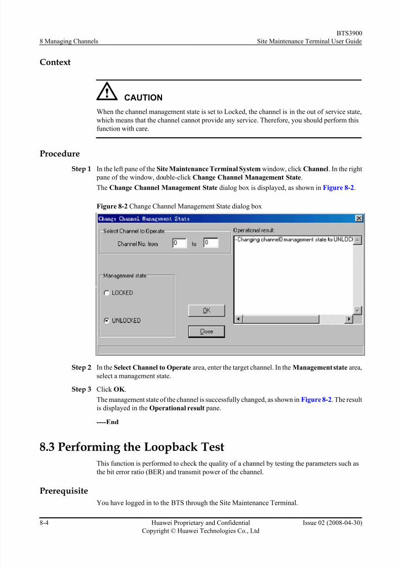
8/10/2019 BTS3900 Site Maintenance Terminal User Guide-(V300R008_02)
http://slidepdf.com/reader/full/bts3900-site-maintenance-terminal-user-guide-v300r00802 78/147
Context
CAUTION
When the channel management state is set to Locked, the channel is in the out of service state,
which means that the channel cannot provide any service. Therefore, you should perform this
function with care.
Procedure
Step 1 In the left pane of the Site Maintenance Terminal System window, click Channel. In the right
pane of the window, double-click Change Channel Management State.
The Change Channel Management State dialog box is displayed, as shown in Figure 8-2.
Figure 8-2 Change Channel Management State dialog box
Step 2 In the Select Channel to Operate area, enter the target channel. In the Management state area,
select a management state.
Step 3 Click OK .
The management state of the channel is successfully changed, as shown in Figure 8-2. The resultis displayed in the Operational result pane.
----End
8.3 Performing the Loopback TestThis function is performed to check the quality of a channel by testing the parameters such as
the bit error ratio (BER) and transmit power of the channel.
Prerequisite
You have logged in to the BTS through the Site Maintenance Terminal.
8 Managing Channels
BTS3900
Site Maintenance Terminal User Guide
8-4 Huawei Proprietary and Confidential
Copyright © Huawei Technologies Co., Ltd
Issue 02 (2008-04-30)

8/10/2019 BTS3900 Site Maintenance Terminal User Guide-(V300R008_02)
http://slidepdf.com/reader/full/bts3900-site-maintenance-terminal-user-guide-v300r00802 79/147
Context
Table 8-2 describes the parameters.
Table 8-2 Parameters in the Cell Extended Attributes Management dialog box
Parameter Meaning Value Range
TRX RF self-loop
test
This test is used to check the performance of the
TX and RX channels on the Um interface.
-
BIU loop test The GTMU provides a loop path for the TRX to
perform the loopback test. This test is used to
check the performance of the DBUS.
-
BTS sound loop
test
This test is used to check whether the connection
of the TCH between the Um interface and the
DBUS is normal.
-
TRX sound loop
test
This test is used to check whether the connection
of the TCH between the Um interface and the
Digital Signal Processor (DSP) is normal.
-
Test time - l TRX RF self-loop
test: 5-65535
seconds
l BIU loop test:
10-65535 seconds
l BTS sound loop
test: 10-600
seconds
l TRX sound loop
test: 10-600
seconds
Power Level The selection of a power level is unavailable
when you perform a BIU loopback test.
0-31
Sub Channel The selection of a sub-channel is unavailable
when you perform a TRX RF loopback test or a
BIU loopback test.
l This parameter
determines the
sub-channel to be
tested in half-rate
configuration.
l In full-rate
configuration,
this parameter is
set to 0xff.
Procedure
Step 1 In the left pane of the Site Maintenance Terminal System window, click Channel. In the right
pane of the window, double-click Channel Loop Test.
The Channel Loop Test dialog box is displayed, as shown in Figure 8-3.
BTS3900
Site Maintenance Terminal User Guide 8 Managing Channels
Issue 02 (2008-04-30) Huawei Proprietary and Confidential
Copyright © Huawei Technologies Co., Ltd
8-5
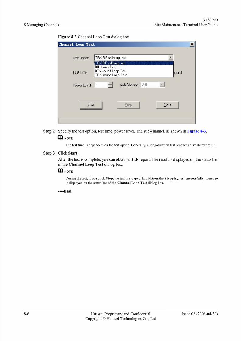
8/10/2019 BTS3900 Site Maintenance Terminal User Guide-(V300R008_02)
http://slidepdf.com/reader/full/bts3900-site-maintenance-terminal-user-guide-v300r00802 80/147
Figure 8-3 Channel Loop Test dialog box
Step 2 Specify the test option, test time, power level, and sub-channel, as shown in Figure 8-3.
NOTE
The test time is dependent on the test option. Generally, a long-duration test produces a stable test result.
Step 3 Click Start.
After the test is complete, you can obtain a BER report. The result is displayed on the status bar
in the Channel Loop Test dialog box.
NOTE
During the test, if you click Stop, the test is stopped. In addition, the Stopping test successfully. messageis displayed on the status bar of the Channel Loop Test dialog box.
----End
8 Managing Channels
BTS3900
Site Maintenance Terminal User Guide
8-6 Huawei Proprietary and Confidential
Copyright © Huawei Technologies Co., Ltd
Issue 02 (2008-04-30)

8/10/2019 BTS3900 Site Maintenance Terminal User Guide-(V300R008_02)
http://slidepdf.com/reader/full/bts3900-site-maintenance-terminal-user-guide-v300r00802 81/147
9 BBU Operations
About This Chapter
The BBU operations involve the query, configuration, and test operations associated with the
BBU. You can query the board settings, board information, board extended information, board
alarms, and port attributes. You can also perform operations such as board reset, power-off reset,
self-test, clock configuration, loopback test, and parameter management.
9.1 Configuring a Board
This describes how to configure a BTS board. After a board is configured, the configuration
information of the board is sent to the BTS through the Site Maintenance Terminal System.
9.2 Querying Board InformationThis describes how to query the board running state, software version, board alarm count, current
clock state, board in-position information, and clock master/backup state.
9.3 Querying Board Extended Information
This describes how to query the E1 port capacity of a board.
9.4 Resetting a board
This function is performed to initialize the parameters associated with a board.
9.5 Resetting a Board in Power-Off Mode
This function is performed to restore the software and hardware parameters of a board to the
initial values.
9.6 Testing a Board
This function is performed to check whether the hardware of the board is damaged.
9.7 Setting the BTS Clock
This describes how to set the working mode of the BTS clock.
9.8 Performing Loopback Test of Board Communication Links
This function is performed to check whether the GTMU communicates with the Site
Maintenance Terminal normally.
9.9 Querying Board Alarms
This function is performed to query board alarm information. The information involves the
object type, object number, alarm level, alarm name, detailed explanation, and recover suggestion.
BTS3900
Site Maintenance Terminal User Guide 9 BBU Operations
Issue 02 (2008-04-30) Huawei Proprietary and Confidential
Copyright © Huawei Technologies Co., Ltd
9-1
8/10/2019 BTS3900 Site Maintenance Terminal User Guide-(V300R008_02)
http://slidepdf.com/reader/full/bts3900-site-maintenance-terminal-user-guide-v300r00802 82/147
9.10 Querying Board Parameters
This function is performed to query the operating parameters of the boards. The parameters are
the board temperature, E1/T1 capacity, fan speed, inlet temperature.
9.11 Querying Port Attributes
This function is performed to query the availability status, management status, active/standbystatus, and physical property of ports.
9 BBU Operations
BTS3900
Site Maintenance Terminal User Guide
9-2 Huawei Proprietary and Confidential
Copyright © Huawei Technologies Co., Ltd
Issue 02 (2008-04-30)

8/10/2019 BTS3900 Site Maintenance Terminal User Guide-(V300R008_02)
http://slidepdf.com/reader/full/bts3900-site-maintenance-terminal-user-guide-v300r00802 83/147
9.1 Configuring a Board
This describes how to configure a BTS board. After a board is configured, the configuration
information of the board is sent to the BTS through the Site Maintenance Terminal System.
Prerequisite
You have logged in to the BTS through the Site Maintenance Terminal.
Procedure
Step 1 In the left pane of the Site Maintenance Terminal System window, click Board. In the right
pane of the window, double-click Board Configuration.
The Board Configuration window is displayed.
Step 2 Right-click a slot, and select a board from the shortcut menu.
The configured board is shown in green on the device panel at first. Then, the system compares
the board configured on the device panel with the board actually installed in the BTS, and
refreshes the displayed result on the device panel.
NOTE
If the board still shows green after the displayed result on the device panel is refreshed, you can infer that
the configured board runs normally.
If the board shows red after the displayed result on the device panel is refreshed, the causes are as follows:
l The board is configured on the device panel while the board is not actually installed in the BTS.
l The board is configured on the device panel and installed in the BTS. However, the communication
between the board and the GTMU cannot be established.
Step 3 Click Refresh.
The system refreshes the result displayed on the device panel. The Configuring board
successfully. message is displayed on the status bar at the bottom of the interface, as shown in
Figure 9-1.
BTS3900
Site Maintenance Terminal User Guide 9 BBU Operations
Issue 02 (2008-04-30) Huawei Proprietary and Confidential
Copyright © Huawei Technologies Co., Ltd
9-3

8/10/2019 BTS3900 Site Maintenance Terminal User Guide-(V300R008_02)
http://slidepdf.com/reader/full/bts3900-site-maintenance-terminal-user-guide-v300r00802 84/147
Figure 9-1 Board Configuration window
----End
9.2 Querying Board Information
This describes how to query the board running state, software version, board alarm count, current
clock state, board in-position information, and clock master/backup state.
Prerequisite
You have logged in to the BTS through the Site Maintenance Terminal.
Context
The querying of the clock master/backup is applicable only to the GTMU.
Procedure
Step 1 Click Board in the left pane of the Site Maintenance Terminal System window, and then
double-click Board Management in the right pane of the window.
The Board Management window is displayed, as shown in Figure 9-2.
9 BBU Operations
BTS3900
Site Maintenance Terminal User Guide
9-4 Huawei Proprietary and Confidential
Copyright © Huawei Technologies Co., Ltd
Issue 02 (2008-04-30)

8/10/2019 BTS3900 Site Maintenance Terminal User Guide-(V300R008_02)
http://slidepdf.com/reader/full/bts3900-site-maintenance-terminal-user-guide-v300r00802 85/147
Figure 9-2 Board Management window
Step 2 Right-click the board to be queried.
A shortcut menu is displayed.
Step 3 Select Board Information from the shortcut menu.
The result is displayed in the Board Information dialog box, as shown in Figure 9-3.
Figure 9-3 Board Information dialog box
----End
9.3 Querying Board Extended InformationThis describes how to query the E1 port capacity of a board.
BTS3900
Site Maintenance Terminal User Guide 9 BBU Operations
Issue 02 (2008-04-30) Huawei Proprietary and Confidential
Copyright © Huawei Technologies Co., Ltd
9-5
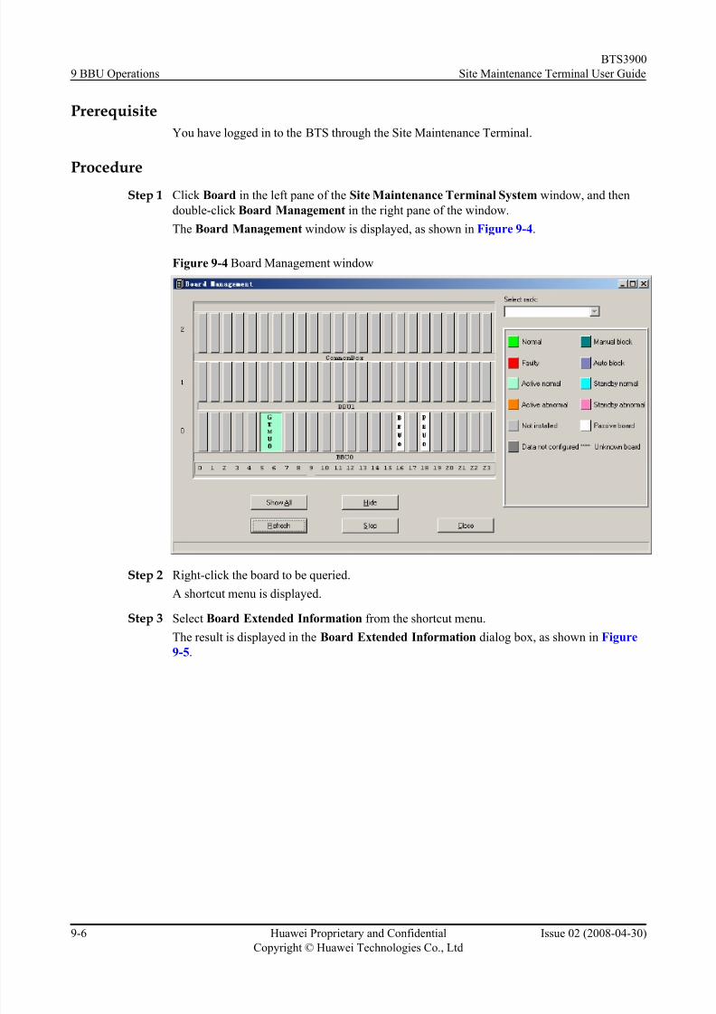
8/10/2019 BTS3900 Site Maintenance Terminal User Guide-(V300R008_02)
http://slidepdf.com/reader/full/bts3900-site-maintenance-terminal-user-guide-v300r00802 86/147
Prerequisite
You have logged in to the BTS through the Site Maintenance Terminal.
Procedure
Step 1 Click Board in the left pane of the Site Maintenance Terminal System window, and then
double-click Board Management in the right pane of the window.
The Board Management window is displayed, as shown in Figure 9-4.
Figure 9-4 Board Management window
Step 2 Right-click the board to be queried.
A shortcut menu is displayed.
Step 3 Select Board Extended Information from the shortcut menu.
The result is displayed in the Board Extended Information dialog box, as shown in Figure
9-5.
9 BBU Operations
BTS3900
Site Maintenance Terminal User Guide
9-6 Huawei Proprietary and Confidential
Copyright © Huawei Technologies Co., Ltd
Issue 02 (2008-04-30)

8/10/2019 BTS3900 Site Maintenance Terminal User Guide-(V300R008_02)
http://slidepdf.com/reader/full/bts3900-site-maintenance-terminal-user-guide-v300r00802 87/147
Figure 9-5 Board Extended Information dialog box
----End
9.4 Resetting a board
This function is performed to initialize the parameters associated with a board.
Prerequisite
You have logged in to the BTS through the Site Maintenance Terminal.
Context
CAUTION
The board reset interrupts the BTS services. Therefore, perform this function with care.
Procedure
Step 1 In the left pane of the Site Maintenance Terminal System window, click Board. In the right
pane of the window, double-click Board Management.
The Board Management window is displayed, as shown in Figure 9-6.
BTS3900
Site Maintenance Terminal User Guide 9 BBU Operations
Issue 02 (2008-04-30) Huawei Proprietary and Confidential
Copyright © Huawei Technologies Co., Ltd
9-7

8/10/2019 BTS3900 Site Maintenance Terminal User Guide-(V300R008_02)
http://slidepdf.com/reader/full/bts3900-site-maintenance-terminal-user-guide-v300r00802 88/147
Figure 9-6 Board Management window
Step 2 Right-click the target board or module, such as GTMU.
A shortcut menu is displayed.
Step 3 Select Reset from the shortcut menu.
The result is displayed in the Board Reset window, as shown in Figure 9-7.
Figure 9-7 Board Reset window
----End
9.5 Resetting a Board in Power-Off Mode
This function is performed to restore the software and hardware parameters of a board to the
initial values.
Prerequisite
You have logged in to the BTS through the Site Maintenance Terminal.
9 BBU Operations
BTS3900
Site Maintenance Terminal User Guide
9-8 Huawei Proprietary and Confidential
Copyright © Huawei Technologies Co., Ltd
Issue 02 (2008-04-30)

8/10/2019 BTS3900 Site Maintenance Terminal User Guide-(V300R008_02)
http://slidepdf.com/reader/full/bts3900-site-maintenance-terminal-user-guide-v300r00802 89/147
Context
CAUTION
The power-off reset of a board interrupts the BTS services. Therefore, perform this function
with care.
Procedure
Step 1 In the left pane of the Site Maintenance Terminal System window, click Board. In the right
pane of the window, double-click Board Management.
The Board Management window is displayed, as shown in Figure 9-8.
Figure 9-8 Board Management window
Step 2 Right-click the board to be reset, such as the GTMU.
A shortcut menu is displayed.
Step 3 Select Power Off Reset from the shortcut menu.
The result is displayed in the Board Reset window, as shown in Figure 9-9.
BTS3900
Site Maintenance Terminal User Guide 9 BBU Operations
Issue 02 (2008-04-30) Huawei Proprietary and Confidential
Copyright © Huawei Technologies Co., Ltd
9-9

8/10/2019 BTS3900 Site Maintenance Terminal User Guide-(V300R008_02)
http://slidepdf.com/reader/full/bts3900-site-maintenance-terminal-user-guide-v300r00802 90/147
Figure 9-9 Board Reset window
----End
9.6 Testing a Board
This function is performed to check whether the hardware of the board is damaged.
Prerequisite
You have logged in to the BTS through the Site Maintenance Terminal.
Procedure
Step 1 Click Board in the left pane of the Site Maintenance Terminal System window, and then
double-click Board Management in the right pane of the window.
The Board Management window is displayed, as shown in Figure 9-10.
Figure 9-10 Board Management window
Step 2 Right-click the board to be tested, such as the GTMU.
A shortcut menu is displayed.
9 BBU Operations
BTS3900
Site Maintenance Terminal User Guide
9-10 Huawei Proprietary and Confidential
Copyright © Huawei Technologies Co., Ltd
Issue 02 (2008-04-30)

8/10/2019 BTS3900 Site Maintenance Terminal User Guide-(V300R008_02)
http://slidepdf.com/reader/full/bts3900-site-maintenance-terminal-user-guide-v300r00802 91/147
Step 3 Select Test from the shortcut menu.
The Board Test dialog box is displayed, as shown in Figure 9-11.
Figure 9-11 Board Test dialog box
NOTE
If the test succeeds, you can infer that that no hardware of the board is damaged.
----End
9.7 Setting the BTS Clock
This describes how to set the working mode of the BTS clock.
PrerequisiteYou have logged in to the BTS through the Site Maintenance Terminal.
Context
This operation applies only to the GTMU. Table 9-1 describes the parameters.
Table 9-1 Parameters in the Clock Setup dialog box
Parameter Meaning ValueRange
Internal clock The clock unit of the BTS works in free oscillationmode. It is not always synchronous with the network
clock.
-
Trace BSC clock The clock unit works in phase-locked mode. It is
synchronous with the 2 Mbit/s clock abstracted from the
Abis interface.
-
External Sync.
clock
The clock unit of the BTS works in phase-locked mode.
It is synchronous with the external 2 MHz reference
clock.
-
Clock Calibration It is used to adjust the frequency of the crystal oscillator. 0-4095
BTS3900
Site Maintenance Terminal User Guide 9 BBU Operations
Issue 02 (2008-04-30) Huawei Proprietary and Confidential
Copyright © Huawei Technologies Co., Ltd
9-11
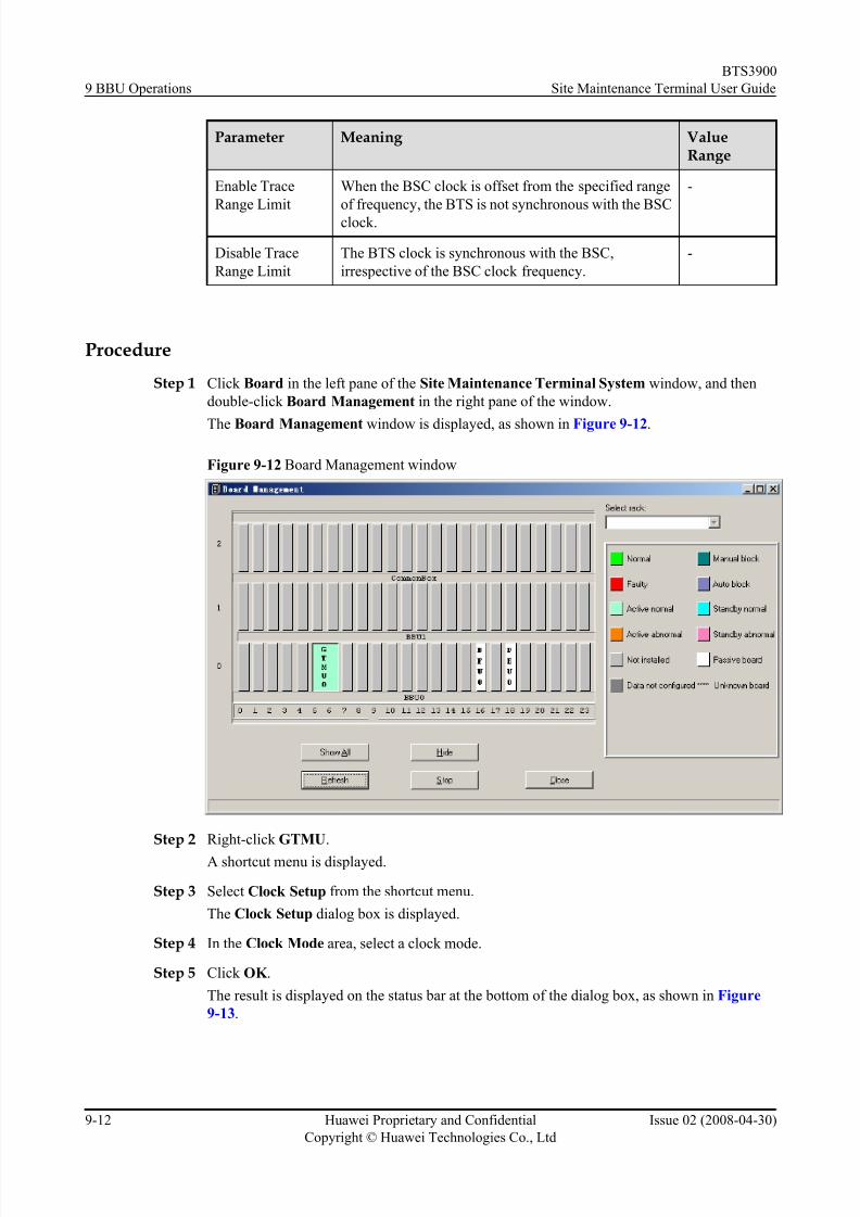
8/10/2019 BTS3900 Site Maintenance Terminal User Guide-(V300R008_02)
http://slidepdf.com/reader/full/bts3900-site-maintenance-terminal-user-guide-v300r00802 92/147
Parameter Meaning ValueRange
Enable Trace
Range Limit
When the BSC clock is offset from the specified range
of frequency, the BTS is not synchronous with the BSC
clock.
-
Disable Trace
Range Limit
The BTS clock is synchronous with the BSC,
irrespective of the BSC clock frequency.
-
Procedure
Step 1 Click Board in the left pane of the Site Maintenance Terminal System window, and then
double-click Board Management in the right pane of the window.
The Board Management window is displayed, as shown in Figure 9-12.
Figure 9-12 Board Management window
Step 2 Right-click GTMU.
A shortcut menu is displayed.
Step 3 Select Clock Setup from the shortcut menu.
The Clock Setup dialog box is displayed.
Step 4 In the Clock Mode area, select a clock mode.
Step 5 Click OK .
The result is displayed on the status bar at the bottom of the dialog box, as shown in Figure
9-13.
9 BBU Operations
BTS3900
Site Maintenance Terminal User Guide
9-12 Huawei Proprietary and Confidential
Copyright © Huawei Technologies Co., Ltd
Issue 02 (2008-04-30)

8/10/2019 BTS3900 Site Maintenance Terminal User Guide-(V300R008_02)
http://slidepdf.com/reader/full/bts3900-site-maintenance-terminal-user-guide-v300r00802 93/147
Figure 9-13 Clock Setup dialog box
Step 6 If you need to change the current clock frequency, specify a value in the Calibration Value(0–
4095) drop-down list box in the Clock Calibration area, and then select Send Calibration
Value. Click OK .
Calibrate the current clock frequency.
Step 7 Select Save Calibration Value. Click OK . The specified clock frequency is saved in the system.
NOTE
In the Clock Mode area, only when you select Trace BSC clock , the Trace Mode can be selected.
----End
9.8 Performing Loopback Test of Board CommunicationLinks
This function is performed to check whether the GTMU communicates with the Site
Maintenance Terminal normally.
Prerequisite
l You have logged in to the BTS through the Site Maintenance Terminal.
l The GTMU to be operated is configured properly and is functional.
Context
This operation applies only to the GTMU. Table 9-2 describes the parameters.
BTS3900
Site Maintenance Terminal User Guide 9 BBU Operations
Issue 02 (2008-04-30) Huawei Proprietary and Confidential
Copyright © Huawei Technologies Co., Ltd
9-13

8/10/2019 BTS3900 Site Maintenance Terminal User Guide-(V300R008_02)
http://slidepdf.com/reader/full/bts3900-site-maintenance-terminal-user-guide-v300r00802 94/147
Table 9-2 Parameters in the Loopback Test dialog box
Parameter Meaning ValueRange
Data length The valid data length of a single frame in the loop testcommand issued by the GTMU.
1-220
Initial data The initial value of the valid data of the loop test
command issued by the GTMU.
0-255
Data step length The incremental step length of the valid data of the loop
test command issued by the GTMU.
0-255
Procedure
Step 1 Click Board in the left pane of the Site Maintenance Terminal System window, and then
double-click Board Management in the right pane of the window.
The Board Management window is displayed, as shown in Figure 9-14.
Figure 9-14 Board Management window
Step 2 Right-click the GTMU.
A shortcut menu is displayed.
Step 3 Select Loop Test from the shortcut menu.
The Loop Test dialog box is displayed, as shown in Figure 9-15.
9 BBU Operations
BTS3900
Site Maintenance Terminal User Guide
9-14 Huawei Proprietary and Confidential
Copyright © Huawei Technologies Co., Ltd
Issue 02 (2008-04-30)

8/10/2019 BTS3900 Site Maintenance Terminal User Guide-(V300R008_02)
http://slidepdf.com/reader/full/bts3900-site-maintenance-terminal-user-guide-v300r00802 95/147
Figure 9-15 Loop Test dialog box
Step 4 Click Start.
After the test is complete, the result is displayed on the status bar at the bottom of the dialog
box.
----End
9.9 Querying Board Alarms
This function is performed to query board alarm information. The information involves the
object type, object number, alarm level, alarm name, detailed explanation, and recover
suggestion.
Prerequisite
You have logged in to the BTS through the Site Maintenance Terminal.
Procedure
Step 1 Click Board in the left pane of the Site Maintenance Terminal System window, and then
double-click Board Management in the right pane of the window.The Board Management window is displayed, as shown in Figure 9-16.
BTS3900
Site Maintenance Terminal User Guide 9 BBU Operations
Issue 02 (2008-04-30) Huawei Proprietary and Confidential
Copyright © Huawei Technologies Co., Ltd
9-15

8/10/2019 BTS3900 Site Maintenance Terminal User Guide-(V300R008_02)
http://slidepdf.com/reader/full/bts3900-site-maintenance-terminal-user-guide-v300r00802 96/147
Figure 9-16 Board Management window
Step 2 Right-click the board to be queried.
A shortcut menu is displayed.
Step 3 Select Board Alarm from the shortcut menu.
The Board Alarm Information dialog box is displayed.
Step 4 Click a red grid.
The description of a specific alarm is displayed in the right pane, as shown in Figure 9-17.
Figure 9-17 Board Alarm Information dialog box
9 BBU Operations
BTS3900
Site Maintenance Terminal User Guide
9-16 Huawei Proprietary and Confidential
Copyright © Huawei Technologies Co., Ltd
Issue 02 (2008-04-30)

8/10/2019 BTS3900 Site Maintenance Terminal User Guide-(V300R008_02)
http://slidepdf.com/reader/full/bts3900-site-maintenance-terminal-user-guide-v300r00802 97/147
NOTE
Each red grid represents an alarm.
----End
9.10 Querying Board Parameters
This function is performed to query the operating parameters of the boards. The parameters are
the board temperature, E1/T1 capacity, fan speed, inlet temperature.
Prerequisite
You have logged in to the BTS through the Site Maintenance Terminal.
Procedure
Step 1 Click Board in the left pane of the Site Maintenance Terminal System window, and then
double-click Board Management in the right pane of the window.
The Board Management window is displayed, as shown in Figure 9-18.
Figure 9-18 Board Management window
Step 2 Right-click the board to be viewed.
A shortcut menu is displayed. Select Parameter Management from the shortcut menu.
Step 3 In the Parameter Management window, click the Running Parameter tab, and query the
running parameters of boards.
The result is displayed on the Parameter Management dialog box, as shown in Figure 9-19.
BTS3900
Site Maintenance Terminal User Guide 9 BBU Operations
Issue 02 (2008-04-30) Huawei Proprietary and Confidential
Copyright © Huawei Technologies Co., Ltd
9-17

8/10/2019 BTS3900 Site Maintenance Terminal User Guide-(V300R008_02)
http://slidepdf.com/reader/full/bts3900-site-maintenance-terminal-user-guide-v300r00802 98/147
Figure 9-19 Parameter Management dialog box
----End
9.11 Querying Port AttributesThis function is performed to query the availability status, management status, active/standby
status, and physical property of ports.
Prerequisite
You have logged in to the BTS through the Site Maintenance Terminal.
Procedure
Step 1 Click Board in the left pane of the Site Maintenance Terminal System window, and then
double-click Board Management in the right pane of the window.The Board Management window is displayed, as shown in Figure 9-20.
9 BBU Operations
BTS3900
Site Maintenance Terminal User Guide
9-18 Huawei Proprietary and Confidential
Copyright © Huawei Technologies Co., Ltd
Issue 02 (2008-04-30)
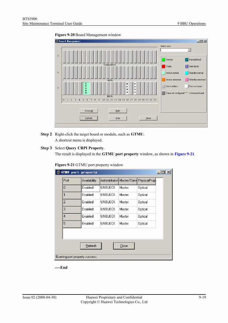
8/10/2019 BTS3900 Site Maintenance Terminal User Guide-(V300R008_02)
http://slidepdf.com/reader/full/bts3900-site-maintenance-terminal-user-guide-v300r00802 99/147
Figure 9-20 Board Management window
Step 2 Right-click the target board or module, such as GTMU.
A shortcut menu is displayed.
Step 3 Select Query CRPI Property.
The result is displayed in the GTMU port property window, as shown in Figure 9-21.
Figure 9-21 GTMU port property window
----End
BTS3900
Site Maintenance Terminal User Guide 9 BBU Operations
Issue 02 (2008-04-30) Huawei Proprietary and Confidential
Copyright © Huawei Technologies Co., Ltd
9-19

8/10/2019 BTS3900 Site Maintenance Terminal User Guide-(V300R008_02)
http://slidepdf.com/reader/full/bts3900-site-maintenance-terminal-user-guide-v300r00802 100/147

8/10/2019 BTS3900 Site Maintenance Terminal User Guide-(V300R008_02)
http://slidepdf.com/reader/full/bts3900-site-maintenance-terminal-user-guide-v300r00802 101/147
10 DRFU Operations
About This Chapter
DRFU operations include the viewing, setting and testing of the DRFU parameters. You can
view the boar d information, board extended information, and board alarms. You can also
perform operations such as the board reset, power-off reset, operation start, self-test, loopback
test, parameter management, and antenna mode configuration.
10.1 Viewing Board Information
This describes how to view the board information. The board information includes the board
running status, alarms, hardware version, software version, services supported, and in-position
boards.
10.2 Viewing Board Extended Information
This describes how to view the board extended information, such as the board type, the operating
frequency band, and services supported by the board.
10.3 Resetting a Board in Power-Off Mode
This describes how to initialize the hardware and software parameters of a board.
10.4 Resetting a Board
This describes how to reset the parameters of a board or channel.
10.5 Starting a Board
This describes how to start the RC on a DRFU.
10.6 Testing a Board
This describes how to test the path of a DRFU.
10.7 Changing the Board Management State
This describes how to lock and unlock a DRFU, and to block and unblock channels on the DRFU.
10.8 Performing Loopback Test on Board Communication Links
This describes how to perform the loopback test on the link between the DRFU and the Site
Maintenance Terminal.
10.9 Viewing Board Alarms
This describes how to query board alarm information. The information include the object type,
object number, alarm level, alarm name, detailed explanation, and recovery suggestion.
BTS3900
Site Maintenance Terminal User Guide 10 DRFU Operations
Issue 02 (2008-04-30) Huawei Proprietary and Confidential
Copyright © Huawei Technologies Co., Ltd
10-1

8/10/2019 BTS3900 Site Maintenance Terminal User Guide-(V300R008_02)
http://slidepdf.com/reader/full/bts3900-site-maintenance-terminal-user-guide-v300r00802 102/147
10.10 Viewing Board Parameters
This describes how to view the operational parameters and configuration parameters of the
DRFU, and the operational parameters of path A and path B.
10.11 Setting the Antenna Mode
This describes how to set the transmit/receive mode of the antenna in accordance with theconfiguration of the DRFU.
10 DRFU Operations
BTS3900
Site Maintenance Terminal User Guide
10-2 Huawei Proprietary and Confidential
Copyright © Huawei Technologies Co., Ltd
Issue 02 (2008-04-30)
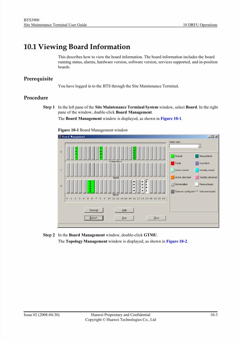
8/10/2019 BTS3900 Site Maintenance Terminal User Guide-(V300R008_02)
http://slidepdf.com/reader/full/bts3900-site-maintenance-terminal-user-guide-v300r00802 103/147
10.1 Viewing Board Information
This describes how to view the board information. The board information includes the board
running status, alarms, hardware version, software version, services supported, and in-position
boards.
Prerequisite
You have logged in to the BTS through the Site Maintenance Terminal.
Procedure
Step 1 In the left pane of the Site Maintenance Terminal System window, select Board. In the right
pane of the window, double-click Board Management.
The Board Management window is displayed, as shown in Figure 10-1.
Figure 10-1 Board Management window
Step 2 In the Board Management window, double-click GTMU.
The Topology Management window is displayed, as shown in Figure 10-2.
BTS3900
Site Maintenance Terminal User Guide 10 DRFU Operations
Issue 02 (2008-04-30) Huawei Proprietary and Confidential
Copyright © Huawei Technologies Co., Ltd
10-3

8/10/2019 BTS3900 Site Maintenance Terminal User Guide-(V300R008_02)
http://slidepdf.com/reader/full/bts3900-site-maintenance-terminal-user-guide-v300r00802 104/147
Figure 10-2 Topology Management window
Step 3 Right-click the DFRU to be queried, and choose Board Information.
The result is displayed in the Board Information dialog box, as shown in Figure 10-3.
Figure 10-3 Board information
----End
10.2 Viewing Board Extended Information
This describes how to view the board extended information, such as the board type, the operatingfrequency band, and services supported by the board.
10 DRFU Operations
BTS3900
Site Maintenance Terminal User Guide
10-4 Huawei Proprietary and Confidential
Copyright © Huawei Technologies Co., Ltd
Issue 02 (2008-04-30)
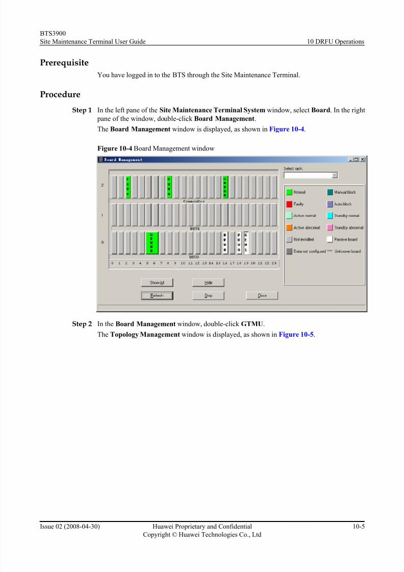
8/10/2019 BTS3900 Site Maintenance Terminal User Guide-(V300R008_02)
http://slidepdf.com/reader/full/bts3900-site-maintenance-terminal-user-guide-v300r00802 105/147
Prerequisite
You have logged in to the BTS through the Site Maintenance Terminal.
Procedure
Step 1 In the left pane of the Site Maintenance Terminal System window, select Board. In the right
pane of the window, double-click Board Management.
The Board Management window is displayed, as shown in Figure 10-4.
Figure 10-4 Board Management window
Step 2 In the Board Management window, double-click GTMU.
The Topology Management window is displayed, as shown in Figure 10-5.
BTS3900
Site Maintenance Terminal User Guide 10 DRFU Operations
Issue 02 (2008-04-30) Huawei Proprietary and Confidential
Copyright © Huawei Technologies Co., Ltd
10-5
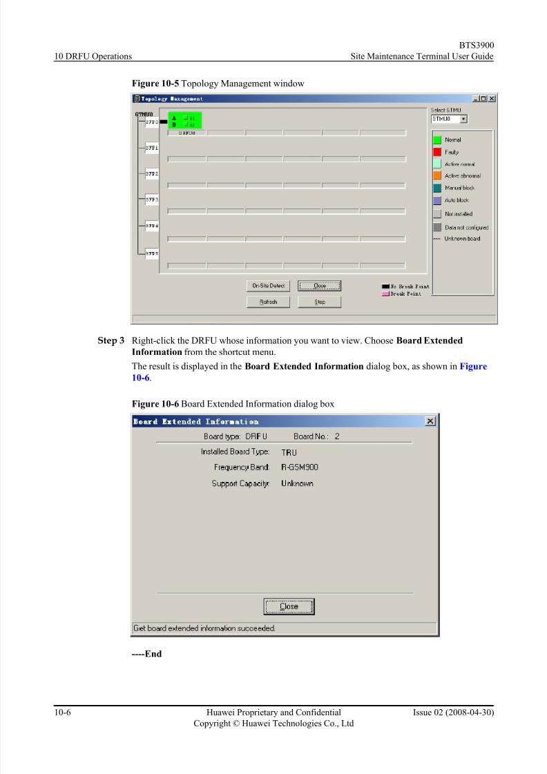
8/10/2019 BTS3900 Site Maintenance Terminal User Guide-(V300R008_02)
http://slidepdf.com/reader/full/bts3900-site-maintenance-terminal-user-guide-v300r00802 106/147
Figure 10-5 Topology Management window
Step 3 Right-click the DRFU whose information you want to view. Choose Board Extended
Information from the shortcut menu.
The result is displayed in the Board Extended Information dialog box, as shown in Figure
10-6.
Figure 10-6 Board Extended Information dialog box
----End
10 DRFU Operations
BTS3900
Site Maintenance Terminal User Guide
10-6 Huawei Proprietary and Confidential
Copyright © Huawei Technologies Co., Ltd
Issue 02 (2008-04-30)

8/10/2019 BTS3900 Site Maintenance Terminal User Guide-(V300R008_02)
http://slidepdf.com/reader/full/bts3900-site-maintenance-terminal-user-guide-v300r00802 107/147
10.3 Resetting a Board in Power-Off Mode
This describes how to initialize the hardware and software parameters of a board.
Prerequisite
You have logged in to the BTS through the Site Maintenance Terminal.
Context
WARNING
The power-off reset of a board interrupts the BTS services. Therefore, perform this function
carefully.
Procedure
Step 1 In the left pane of the Site Maintenance Terminal System window, select Board. In the right
pane of the window, double-click Board Management.
The Board Management window is displayed, as shown in Figure 10-7.
Figure 10-7 Board Management window
Step 2 In the Board Management window, double-click GTMU.
The Topology Management window is displayed, as shown in Figure 10-8.
BTS3900
Site Maintenance Terminal User Guide 10 DRFU Operations
Issue 02 (2008-04-30) Huawei Proprietary and Confidential
Copyright © Huawei Technologies Co., Ltd
10-7

8/10/2019 BTS3900 Site Maintenance Terminal User Guide-(V300R008_02)
http://slidepdf.com/reader/full/bts3900-site-maintenance-terminal-user-guide-v300r00802 108/147
Figure 10-8 Topology Management window
Step 3 In the Topology Management window, right-click the target DRFU module.
A shortcut menu is displayed, as shown in Figure 10-9.
Figure 10-9 Choosing Power Off Reset
Step 4 Choose Power Off Reset on the shortcut menu.
The result is displayed in the Board Reset window, as shown in Figure 10-10.
10 DRFU Operations
BTS3900
Site Maintenance Terminal User Guide
10-8 Huawei Proprietary and Confidential
Copyright © Huawei Technologies Co., Ltd
Issue 02 (2008-04-30)
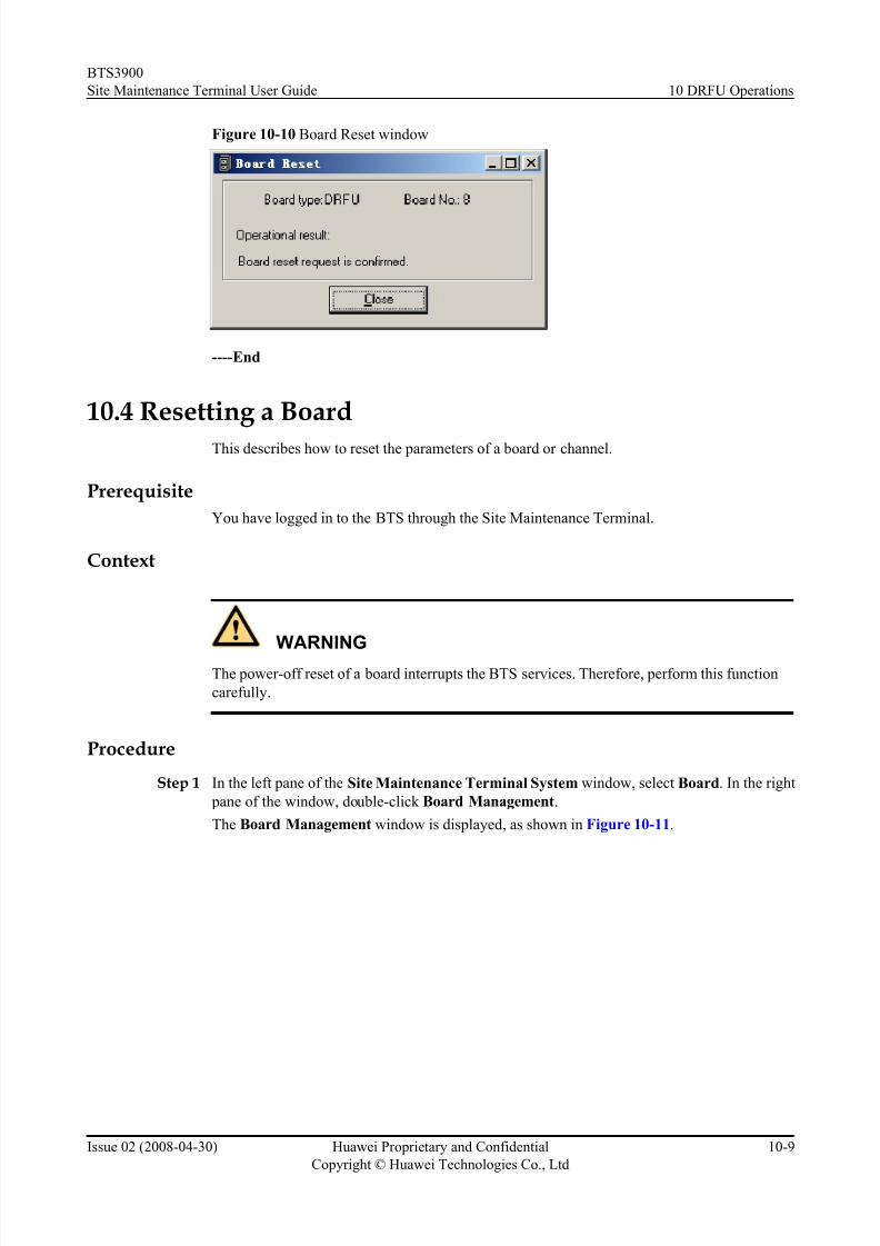
8/10/2019 BTS3900 Site Maintenance Terminal User Guide-(V300R008_02)
http://slidepdf.com/reader/full/bts3900-site-maintenance-terminal-user-guide-v300r00802 109/147
Figure 10-10 Board Reset window
----End
10.4 Resetting a Board
This describes how to reset the parameters of a board or channel.
Prerequisite
You have logged in to the BTS through the Site Maintenance Terminal.
Context
WARNING
The power-off reset of a board interrupts the BTS services. Therefore, perform this function
carefully.
Procedure
Step 1 In the left pane of the Site Maintenance Terminal System window, select Board. In the right
pane of the window, double-click Board Management.
The Board Management window is displayed, as shown in Figure 10-11.
BTS3900
Site Maintenance Terminal User Guide 10 DRFU Operations
Issue 02 (2008-04-30) Huawei Proprietary and Confidential
Copyright © Huawei Technologies Co., Ltd
10-9
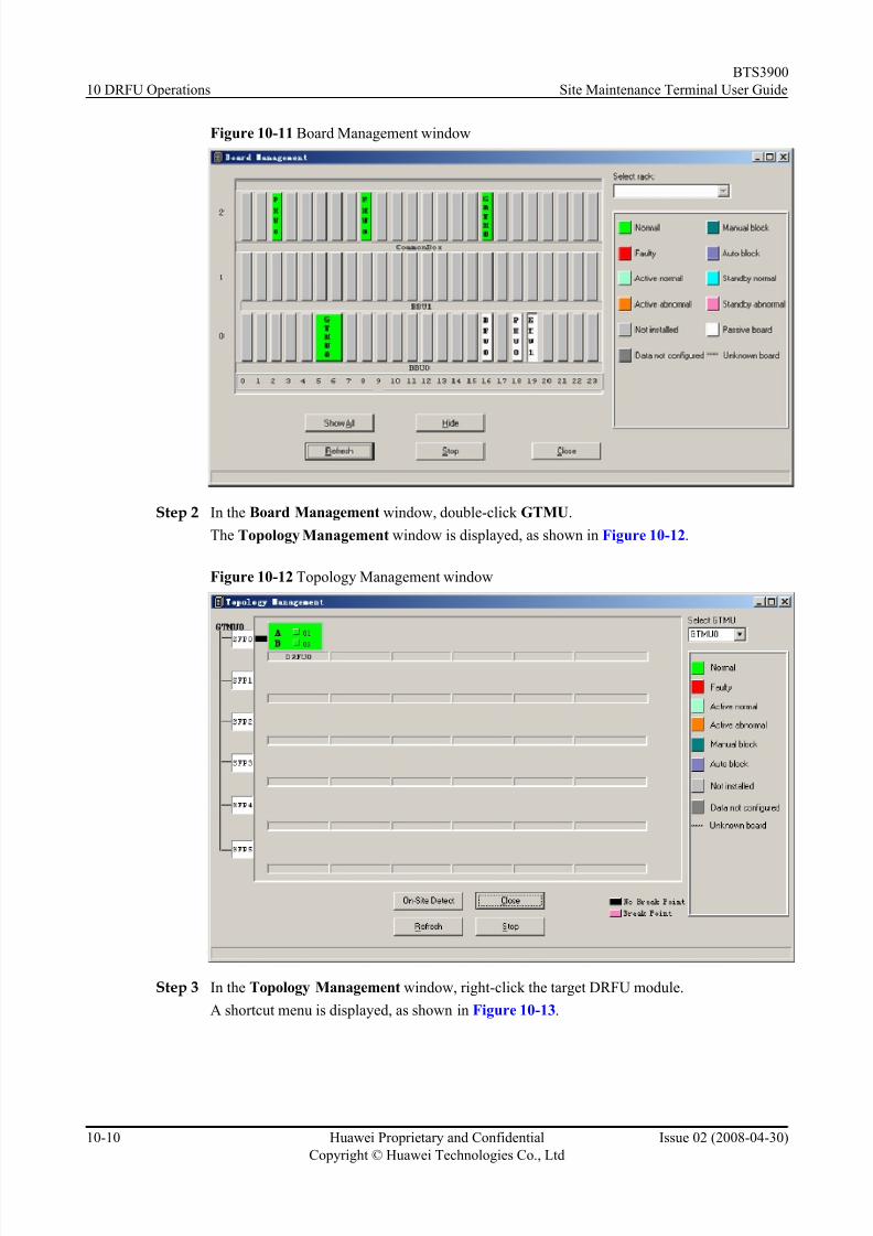
8/10/2019 BTS3900 Site Maintenance Terminal User Guide-(V300R008_02)
http://slidepdf.com/reader/full/bts3900-site-maintenance-terminal-user-guide-v300r00802 110/147
Figure 10-11 Board Management window
Step 2 In the Board Management window, double-click GTMU.
The Topology Management window is displayed, as shown in Figure 10-12.
Figure 10-12 Topology Management window
Step 3 In the Topology Management window, right-click the target DRFU module.
A shortcut menu is displayed, as shown in Figure 10-13.
10 DRFU Operations
BTS3900
Site Maintenance Terminal User Guide
10-10 Huawei Proprietary and Confidential
Copyright © Huawei Technologies Co., Ltd
Issue 02 (2008-04-30)

8/10/2019 BTS3900 Site Maintenance Terminal User Guide-(V300R008_02)
http://slidepdf.com/reader/full/bts3900-site-maintenance-terminal-user-guide-v300r00802 111/147

8/10/2019 BTS3900 Site Maintenance Terminal User Guide-(V300R008_02)
http://slidepdf.com/reader/full/bts3900-site-maintenance-terminal-user-guide-v300r00802 112/147
Click OK to perform path resetting.
----End
10.5 Starting a BoardThis describes how to start the RC on a DRFU.
Prerequisite
You have logged in to the BTS through the Site Maintenance Terminal.
Procedure
Step 1 In the left pane of the Site Maintenance Terminal System window, select Board. In the right
pane of the window, double-click Board Management.
The Board Management window is displayed, as shown in Figure 10-16.
Figure 10-16 Board Management window
Step 2 In the Board Management window, double-click GTMU.The Topology Management window is displayed, as shown in Figure 10-17.
10 DRFU Operations
BTS3900
Site Maintenance Terminal User Guide
10-12 Huawei Proprietary and Confidential
Copyright © Huawei Technologies Co., Ltd
Issue 02 (2008-04-30)

8/10/2019 BTS3900 Site Maintenance Terminal User Guide-(V300R008_02)
http://slidepdf.com/reader/full/bts3900-site-maintenance-terminal-user-guide-v300r00802 113/147
Figure 10-17 Topology Management window
Step 3 In the Topology Management window, right-click the target DRFU module,
as shown in Figure 10-18.
Figure 10-18 Choosing Opstart
Step 4 Choose the path to be tested, for example, Pass A.
The Opstart dialog box is displayed, as shown in Figure 10-19.
NOTE
Pass A and Pass B refer to two RCs on the DRFU.
BTS3900
Site Maintenance Terminal User Guide 10 DRFU Operations
Issue 02 (2008-04-30) Huawei Proprietary and Confidential
Copyright © Huawei Technologies Co., Ltd
10-13

8/10/2019 BTS3900 Site Maintenance Terminal User Guide-(V300R008_02)
http://slidepdf.com/reader/full/bts3900-site-maintenance-terminal-user-guide-v300r00802 114/147
Figure 10-19 Opstart dialog box
----End
10.6 Testing a BoardThis describes how to test the path of a DRFU.
Prerequisite
You have logged in to the BTS through the Site Maintenance Terminal.
Procedure
Step 1 In the left pane of the Site Maintenance Terminal System window, select Board. In the right
pane of the window, double-click Board Management.
The Board Management window is displayed, as shown in Figure 10-20.
Figure 10-20 Board Management window
Step 2 In the Board Management window, double-click GTMU.
The Topology Management window is displayed, as shown in Figure 10-21.
10 DRFU Operations
BTS3900
Site Maintenance Terminal User Guide
10-14 Huawei Proprietary and Confidential
Copyright © Huawei Technologies Co., Ltd
Issue 02 (2008-04-30)

8/10/2019 BTS3900 Site Maintenance Terminal User Guide-(V300R008_02)
http://slidepdf.com/reader/full/bts3900-site-maintenance-terminal-user-guide-v300r00802 115/147
Figure 10-21 Topology Management window
Step 3 In the Topology Management window, right-click the target DRFU module.
A shortcut menu is displayed, as shown in Figure 10-22.
Figure 10-22 Choosing the path to be tested
Step 4 Choose the path to be tested, for example, Pass A.
The result is displayed in the Board Test dialog box, as shown in Figure 10-23.
BTS3900
Site Maintenance Terminal User Guide 10 DRFU Operations
Issue 02 (2008-04-30) Huawei Proprietary and Confidential
Copyright © Huawei Technologies Co., Ltd
10-15

8/10/2019 BTS3900 Site Maintenance Terminal User Guide-(V300R008_02)
http://slidepdf.com/reader/full/bts3900-site-maintenance-terminal-user-guide-v300r00802 116/147
Figure 10-23 Board Test dialog box
NOTE
A successful test indicates that the path works normally.
----End
10.7 Changing the Board Management State
This describes how to lock and unlock a DRFU, and to block and unblock channels on the DRFU.
Prerequisite
You have logged in to the BTS through the Site Maintenance Terminal.
Procedure
Step 1 In the left pane of the Site Maintenance Terminal System window, select Board. In the right
pane of the window, double-click Board Management.
The Board Management window is displayed, as shown in Figure 10-24.
Figure 10-24 Board Management window
10 DRFU Operations
BTS3900
Site Maintenance Terminal User Guide
10-16 Huawei Proprietary and Confidential
Copyright © Huawei Technologies Co., Ltd
Issue 02 (2008-04-30)

8/10/2019 BTS3900 Site Maintenance Terminal User Guide-(V300R008_02)
http://slidepdf.com/reader/full/bts3900-site-maintenance-terminal-user-guide-v300r00802 117/147
Step 2 In the Board Management window, double-click GTMU.
The Topology Management window is displayed, as shown in Figure 10-25.
Figure 10-25 Topology Management window
Step 3 In the Topology Management window, right-click the target DRFU. Choose Management
state > Locked, as shown in Figure 10-26.
Figure 10-26 Choosing Management state
Step 4 Choose Locked.
The LOCKED dialog box is displayed, as shown in Figure 10-27.
BTS3900
Site Maintenance Terminal User Guide 10 DRFU Operations
Issue 02 (2008-04-30) Huawei Proprietary and Confidential
Copyright © Huawei Technologies Co., Ltd
10-17

8/10/2019 BTS3900 Site Maintenance Terminal User Guide-(V300R008_02)
http://slidepdf.com/reader/full/bts3900-site-maintenance-terminal-user-guide-v300r00802 118/147
Figure 10-27 LOCKED dialog box
Step 5 Choose Unlocked.
The UNLOCKED dialog box is displayed, as shown in Figure 10-28.
Figure 10-28 UNLOCKED dialog box
Step 6 To block or unblock a channel on the TRX, choose Management stateBlock Channel.
A cascaded shortcut menu is displayed, as shown in Figure 10-29.
10 DRFU Operations
BTS3900
Site Maintenance Terminal User Guide
10-18 Huawei Proprietary and Confidential
Copyright © Huawei Technologies Co., Ltd
Issue 02 (2008-04-30)

8/10/2019 BTS3900 Site Maintenance Terminal User Guide-(V300R008_02)
http://slidepdf.com/reader/full/bts3900-site-maintenance-terminal-user-guide-v300r00802 119/147

8/10/2019 BTS3900 Site Maintenance Terminal User Guide-(V300R008_02)
http://slidepdf.com/reader/full/bts3900-site-maintenance-terminal-user-guide-v300r00802 120/147
Context
Table 10-1 lists the descriptions of the parameters.
Table 10-1 Parameters in the Loop Test dialog box
ParameterName
Meaning ValueRange
Data Length Refers to the length of the valid data of the single frame
of the loopback test command.
1-220
Initial Data Refers to the initial value of the valid data in the
loopback test command.
0-255
Data Step Length Refers to the incremental step length of the valid data in
the loopback test command.
0-255
Procedure
Step 1 In the left pane of the Site Maintenance Terminal System window, select Board. In the right
pane of the window, double-click Board Management.
The Board Management window is displayed, as shown in Figure 10-31.
Figure 10-31 Board Management window
Step 2 In the Board Management window, double-click GTMU.
The Topology Management window is displayed, as shown in Figure 10-32.
10 DRFU Operations
BTS3900
Site Maintenance Terminal User Guide
10-20 Huawei Proprietary and Confidential
Copyright © Huawei Technologies Co., Ltd
Issue 02 (2008-04-30)

8/10/2019 BTS3900 Site Maintenance Terminal User Guide-(V300R008_02)
http://slidepdf.com/reader/full/bts3900-site-maintenance-terminal-user-guide-v300r00802 121/147
Figure 10-32 Topology Management window
Step 3 In the Topology Management window, right-click the target DRFU module,
as shown in Figure 10-33.
Figure 10-33 Choosing Loop Test
Step 4 Choose Pass A or Pass B to be tested.
The Loop Test dialog box is displayed, as shown in Figure 10-34.
BTS3900
Site Maintenance Terminal User Guide 10 DRFU Operations
Issue 02 (2008-04-30) Huawei Proprietary and Confidential
Copyright © Huawei Technologies Co., Ltd
10-21

8/10/2019 BTS3900 Site Maintenance Terminal User Guide-(V300R008_02)
http://slidepdf.com/reader/full/bts3900-site-maintenance-terminal-user-guide-v300r00802 122/147
Figure 10-34 Loop Test dialog box
Step 5 Click Start.
After the test is complete, the result is displayed on the status bar.
----End
10.9 Viewing Board Alarms
This describes how to query board alarm information. The information include the object type,object number, alarm level, alarm name, detailed explanation, and recovery suggestion.
Prerequisite
You have logged in to the BTS through the Site Maintenance Terminal.
Procedure
Step 1 In the left pane of the Site Maintenance Terminal System window, select Board. In the right
pane of the window, double-click Board Management.
The Board Management window is displayed, as shown in Figure 10-35.
10 DRFU Operations
BTS3900
Site Maintenance Terminal User Guide
10-22 Huawei Proprietary and Confidential
Copyright © Huawei Technologies Co., Ltd
Issue 02 (2008-04-30)

8/10/2019 BTS3900 Site Maintenance Terminal User Guide-(V300R008_02)
http://slidepdf.com/reader/full/bts3900-site-maintenance-terminal-user-guide-v300r00802 123/147
Figure 10-35 Board Management window
Step 2 In the Board Management window, double-click GTMU.
The Topology Management window is displayed, as shown in Figure 10-36.
Figure 10-36 Topology Management window
Step 3 Right-click the DRFU whose information you want to view. Choose Board Alarm on the
shortcut menu.
The result is displayed in the Board Alarm Information dialog box, as shown in Figure
10-37.
BTS3900
Site Maintenance Terminal User Guide 10 DRFU Operations
Issue 02 (2008-04-30) Huawei Proprietary and Confidential
Copyright © Huawei Technologies Co., Ltd
10-23

8/10/2019 BTS3900 Site Maintenance Terminal User Guide-(V300R008_02)
http://slidepdf.com/reader/full/bts3900-site-maintenance-terminal-user-guide-v300r00802 124/147
Figure 10-37 Board Alarm Information dialog box
NOTE
A red grid represents an alarm.
----End
10.10 Viewing Board Parameters
This describes how to view the operational parameters and configuration parameters of the
DRFU, and the operational parameters of path A and path B.
Prerequisite
You have logged in to the BTS through the Site Maintenance Terminal.
Procedure
Step 1 In the left pane of the Site Maintenance Terminal System window, select Board. In the right pane of the window, double-click Board Management.
The Board Management window is displayed, as shown in Figure 10-38.
10 DRFU Operations
BTS3900
Site Maintenance Terminal User Guide
10-24 Huawei Proprietary and Confidential
Copyright © Huawei Technologies Co., Ltd
Issue 02 (2008-04-30)
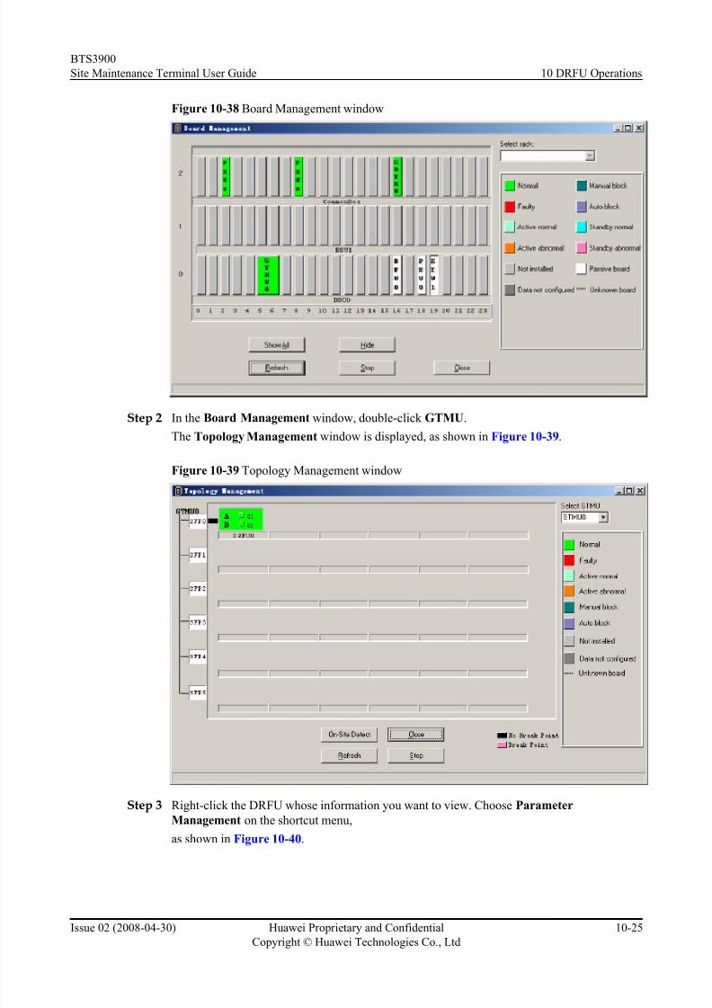
8/10/2019 BTS3900 Site Maintenance Terminal User Guide-(V300R008_02)
http://slidepdf.com/reader/full/bts3900-site-maintenance-terminal-user-guide-v300r00802 125/147
Figure 10-38 Board Management window
Step 2 In the Board Management window, double-click GTMU.
The Topology Management window is displayed, as shown in Figure 10-39.
Figure 10-39 Topology Management window
Step 3 Right-click the DRFU whose information you want to view. Choose Parameter
Management on the shortcut menu,
as shown in Figure 10-40.
BTS3900
Site Maintenance Terminal User Guide 10 DRFU Operations
Issue 02 (2008-04-30) Huawei Proprietary and Confidential
Copyright © Huawei Technologies Co., Ltd
10-25

8/10/2019 BTS3900 Site Maintenance Terminal User Guide-(V300R008_02)
http://slidepdf.com/reader/full/bts3900-site-maintenance-terminal-user-guide-v300r00802 126/147
Figure 10-40 Choosing Parameter Management
Step 4 To view and set the operational and configuration parameters associated with a board, choose
Board.
The Parameter Management window is displayed, as shown in Figure 10-41, Figure 10-42
and Figure 10-43.
Figure 10-41 Viewing the operational parameters
10 DRFU Operations
BTS3900
Site Maintenance Terminal User Guide
10-26 Huawei Proprietary and Confidential
Copyright © Huawei Technologies Co., Ltd
Issue 02 (2008-04-30)

8/10/2019 BTS3900 Site Maintenance Terminal User Guide-(V300R008_02)
http://slidepdf.com/reader/full/bts3900-site-maintenance-terminal-user-guide-v300r00802 127/147
Figure 10-42 Viewing the configuration parameters
Figure 10-43 Setting the parameters
Step 5 To view the operational parameters of a channel, choose Pass A or Pass B.
The Parameter Management dialog box associated with the path A or B is displayed, as shownin Figure 10-44.
BTS3900
Site Maintenance Terminal User Guide 10 DRFU Operations
Issue 02 (2008-04-30) Huawei Proprietary and Confidential
Copyright © Huawei Technologies Co., Ltd
10-27

8/10/2019 BTS3900 Site Maintenance Terminal User Guide-(V300R008_02)
http://slidepdf.com/reader/full/bts3900-site-maintenance-terminal-user-guide-v300r00802 128/147
Figure 10-44 Viewing the operational parameters of a path
----End
10.11 Setting the Antenna ModeThis describes how to set the transmit/receive mode of the antenna in accordance with the
configuration of the DRFU.
Prerequisite
You have logged in to the BTS through the Site Maintenance Terminal.
Procedure
Step 1 In the left pane of the Site Maintenance Terminal System window, select Board. In the right
pane of the window, double-click Board Management.The Board Management window is displayed, as shown in Figure 10-45.
10 DRFU Operations
BTS3900
Site Maintenance Terminal User Guide
10-28 Huawei Proprietary and Confidential
Copyright © Huawei Technologies Co., Ltd
Issue 02 (2008-04-30)

8/10/2019 BTS3900 Site Maintenance Terminal User Guide-(V300R008_02)
http://slidepdf.com/reader/full/bts3900-site-maintenance-terminal-user-guide-v300r00802 129/147
Figure 10-45 Board Management window
Step 2 In the Board Management window, double-click GTMU.
The Topology Management window is displayed, as shown in Figure 10-46.
Figure 10-46 Topology Management window
Step 3 In the Topology Management window, right-click the target DRFU,
as shown in Figure 10-47.
BTS3900
Site Maintenance Terminal User Guide 10 DRFU Operations
Issue 02 (2008-04-30) Huawei Proprietary and Confidential
Copyright © Huawei Technologies Co., Ltd
10-29
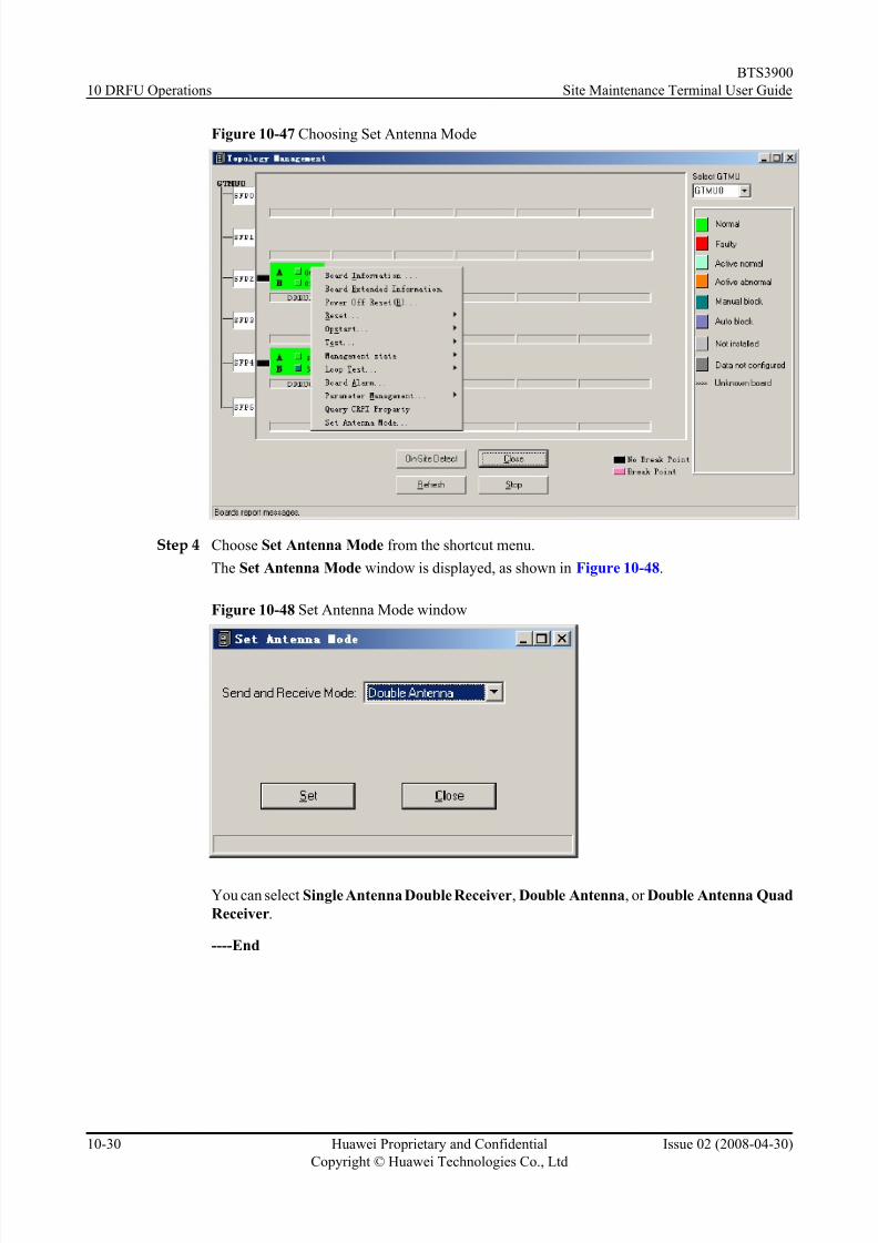
8/10/2019 BTS3900 Site Maintenance Terminal User Guide-(V300R008_02)
http://slidepdf.com/reader/full/bts3900-site-maintenance-terminal-user-guide-v300r00802 130/147
Figure 10-47 Choosing Set Antenna Mode
Step 4 Choose Set Antenna Mode from the shortcut menu.
The Set Antenna Mode window is displayed, as shown in Figure 10-48.
Figure 10-48 Set Antenna Mode window
You can select Single Antenna Double Receiver, Double Antenna, or Double Antenna Quad
Receiver.
----End
10 DRFU Operations
BTS3900
Site Maintenance Terminal User Guide
10-30 Huawei Proprietary and Confidential
Copyright © Huawei Technologies Co., Ltd
Issue 02 (2008-04-30)
8/10/2019 BTS3900 Site Maintenance Terminal User Guide-(V300R008_02)
http://slidepdf.com/reader/full/bts3900-site-maintenance-terminal-user-guide-v300r00802 131/147
11 DRFU Configuration
About This Chapter
This describes how to perform various operations on the DRFU based on the actual requirement,
such as adding or deleting an DRFU, adding or removing a ring, displaying in-position boards,
detecting in-position boards, setting and canceling a breakpoint.
11.1 Adding a DRFU
This describes how to deploy a DRFU into a required position by specifying the board number,
SFP number, and hop number.
11.2 Deleting a DRFU
This describes how to delete a DRFU by specifying the SFP number and the hop number.
11.3 Adding a Ring
This describes how to form a DRFU ring using two independent DRFU chains.
11.4 Dividing a Ring
This describes how to divide a DRFU ring into two independent DRFU chains.
11.5 Displaying In-Position Boards
This describes how to check whether there are in-position boards in the BTS. An in-position
board is a board that is installed in the BTS cabinet and whose data is not configured.
11.6 Detecting In-Position Boards
This describes how to detect the information about the in-position boards.
11.7 Setting a Breakpoint
This describes how to set a breakpoint on a DRFU chain or ring. A DRFU chain can be configured
with only one breakpoint. After a breakpoint is configured, the DRFU chain is divided into two
parts. A DRFU ring can be configured with two breakpoints. After two breakpoints are
configured, the DRFU ring is divided into three parts.
11.8 Canceling a Breakpoint
This describes how to cancel a breakpoint set on a DRFU chain or ring.
BTS3900
Site Maintenance Terminal User Guide 11 DRFU Configuration
Issue 02 (2008-04-30) Huawei Proprietary and Confidential
Copyright © Huawei Technologies Co., Ltd
11-1

8/10/2019 BTS3900 Site Maintenance Terminal User Guide-(V300R008_02)
http://slidepdf.com/reader/full/bts3900-site-maintenance-terminal-user-guide-v300r00802 132/147
11.1 Adding a DRFU
This describes how to deploy a DRFU into a required position by specifying the board number,
SFP number, and hop number.
Prerequisite
You have logged in to the BTS through the Site Maintenance Terminal.
Procedure
Step 1 In the left pane of the Site Maintenance Terminal System window, select Board. In the right
pane of the window, double-click Board Configuration.
The Board Configuration window is displayed, as shown in Figure 11-1.
Figure 11-1 Board Configuration window
Step 2 In the Board Configuration window, double-click GTMU.
The Topology Configuration window is displayed, as shown in Figure 11-2.
11 DRFU Configuration
BTS3900
Site Maintenance Terminal User Guide
11-2 Huawei Proprietary and Confidential
Copyright © Huawei Technologies Co., Ltd
Issue 02 (2008-04-30)

8/10/2019 BTS3900 Site Maintenance Terminal User Guide-(V300R008_02)
http://slidepdf.com/reader/full/bts3900-site-maintenance-terminal-user-guide-v300r00802 133/147
Figure 11-2 Topology Configuration window
Step 3 In the Topology Configuration window, click Add RRU.
The Deploy DRRU window is displayed. Select DRFU under the Card Type, as shown in
Figure 11-3.
Figure 11-3 Deploy DRRU window
NOTE
The SFP number ranges from 0 to 5. The hop number ranges from 1 to 6.
Step 4 In the Deploy DRRU window, select the board number, SFP number, and hop number of the
DRFU to be added,
as shown in Figure 11-4.
BTS3900
Site Maintenance Terminal User Guide 11 DRFU Configuration
Issue 02 (2008-04-30) Huawei Proprietary and Confidential
Copyright © Huawei Technologies Co., Ltd
11-3

8/10/2019 BTS3900 Site Maintenance Terminal User Guide-(V300R008_02)
http://slidepdf.com/reader/full/bts3900-site-maintenance-terminal-user-guide-v300r00802 134/147
Figure 11-4 Deploy DRRU window
Step 5 In the Deploy DRRU window, click OK . Adding the DRFU is complete.The Topology Configuration window is displayed, as shown in Figure 11-5.
Figure 11-5 Topology Configuration window
----End
11.2 Deleting a DRFU
This describes how to delete a DRFU by specifying the SFP number and the hop number.
Prerequisite
You have logged in to the BTS through the Site Maintenance Terminal.
11 DRFU Configuration
BTS3900
Site Maintenance Terminal User Guide
11-4 Huawei Proprietary and Confidential
Copyright © Huawei Technologies Co., Ltd
Issue 02 (2008-04-30)

8/10/2019 BTS3900 Site Maintenance Terminal User Guide-(V300R008_02)
http://slidepdf.com/reader/full/bts3900-site-maintenance-terminal-user-guide-v300r00802 135/147

8/10/2019 BTS3900 Site Maintenance Terminal User Guide-(V300R008_02)
http://slidepdf.com/reader/full/bts3900-site-maintenance-terminal-user-guide-v300r00802 136/147
Step 3 In the Topology Configuration window, click Remove RRU.
The Delete DRRU window is displayed, as shown in Figure 11-8.
Figure 11-8 Delete DRRU window
NOTE
The SFP number ranges from 0 to 5. The hop number ranges from 1 to 6.
Step 4 In the Delete DRRU window, select the SFP number and the hop number of the DRFU to be
deleted, and then click OK . Deleting the DRFU is complete.
----End
11.3 Adding a Ring
This describes how to form a DRFU ring using two independent DRFU chains.
Prerequisite
You have logged in to the BTS through the Site Maintenance Terminal.
Procedure
Step 1 In the left pane of the Site Maintenance Terminal System window, select Board. In the right
pane of the window, double-click Board Configuration.
The Board Configuration window is displayed, as shown in Figure 11-9.
11 DRFU Configuration
BTS3900
Site Maintenance Terminal User Guide
11-6 Huawei Proprietary and Confidential
Copyright © Huawei Technologies Co., Ltd
Issue 02 (2008-04-30)

8/10/2019 BTS3900 Site Maintenance Terminal User Guide-(V300R008_02)
http://slidepdf.com/reader/full/bts3900-site-maintenance-terminal-user-guide-v300r00802 137/147
Figure 11-9 Board Configuration window
Step 2 In the Board Configuration window, double-click GTMU.
The Topology Configuration window is displayed, as shown in Figure 11-10.
Figure 11-10 Topology Configuration window
Step 3 In the Topology Configuration window, click Add Ring.
The Add Ring window is displayed, as shown in Figure 11-11.
BTS3900
Site Maintenance Terminal User Guide 11 DRFU Configuration
Issue 02 (2008-04-30) Huawei Proprietary and Confidential
Copyright © Huawei Technologies Co., Ltd
11-7
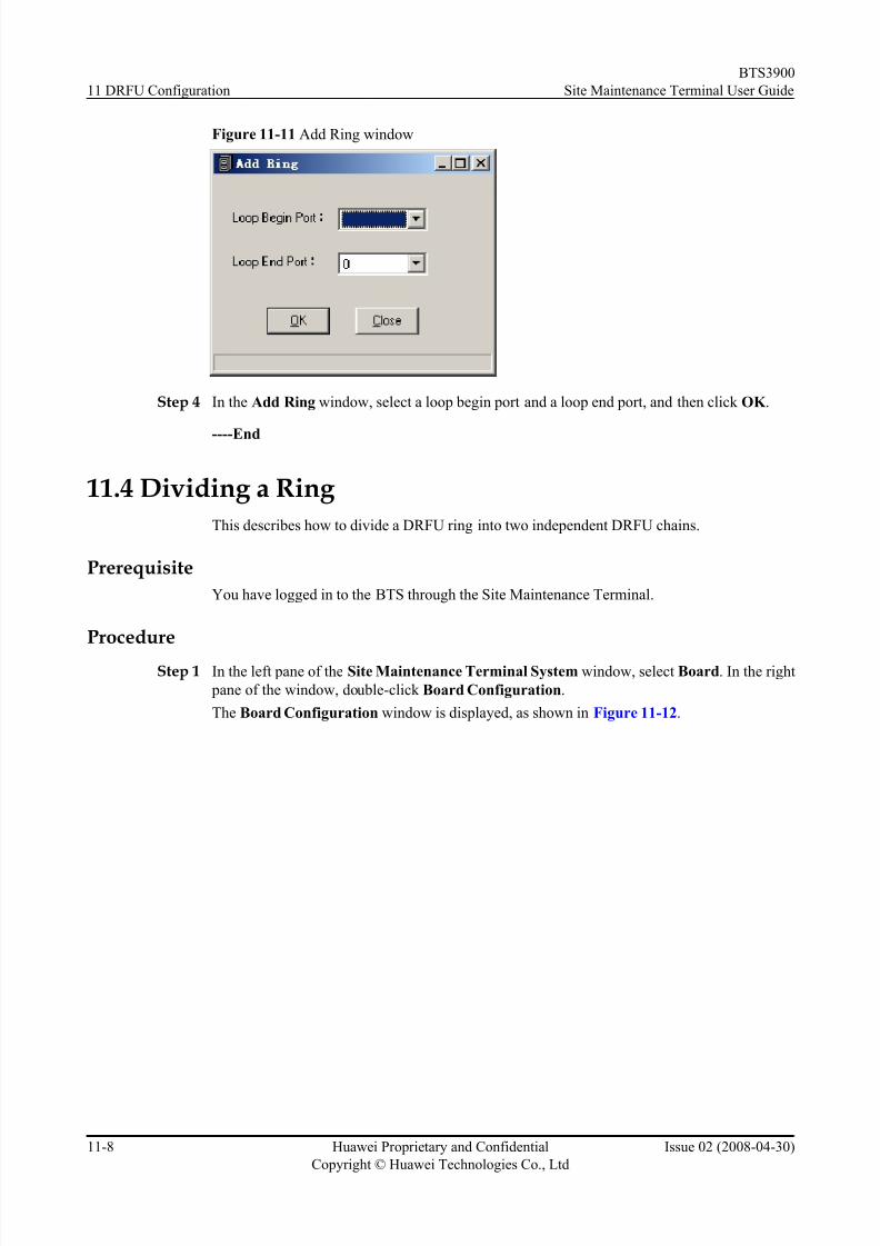
8/10/2019 BTS3900 Site Maintenance Terminal User Guide-(V300R008_02)
http://slidepdf.com/reader/full/bts3900-site-maintenance-terminal-user-guide-v300r00802 138/147
Figure 11-11 Add Ring window
Step 4 In the Add Ring window, select a loop begin port and a loop end port, and then click OK .
----End
11.4 Dividing a Ring
This describes how to divide a DRFU ring into two independent DRFU chains.
Prerequisite
You have logged in to the BTS through the Site Maintenance Terminal.
Procedure
Step 1 In the left pane of the Site Maintenance Terminal System window, select Board. In the right
pane of the window, double-click Board Configuration.
The Board Configuration window is displayed, as shown in Figure 11-12.
11 DRFU Configuration
BTS3900
Site Maintenance Terminal User Guide
11-8 Huawei Proprietary and Confidential
Copyright © Huawei Technologies Co., Ltd
Issue 02 (2008-04-30)

8/10/2019 BTS3900 Site Maintenance Terminal User Guide-(V300R008_02)
http://slidepdf.com/reader/full/bts3900-site-maintenance-terminal-user-guide-v300r00802 139/147
Figure 11-12 Board Configuration window
Step 2 In the Board Configuration window, double-click GTMU.
The Topology Configuration window is displayed, as shown in Figure 11-13.
Figure 11-13 Topology Configuration window
Step 3 In the Topology Configuration window, click Remove Ring.
The Divide Ring window is displayed, as shown in Figure 11-14.
BTS3900
Site Maintenance Terminal User Guide 11 DRFU Configuration
Issue 02 (2008-04-30) Huawei Proprietary and Confidential
Copyright © Huawei Technologies Co., Ltd
11-9

8/10/2019 BTS3900 Site Maintenance Terminal User Guide-(V300R008_02)
http://slidepdf.com/reader/full/bts3900-site-maintenance-terminal-user-guide-v300r00802 140/147
Figure 11-14 Divide Ring window
Step 4 In the Divide Ring window, select a loop begin port and a divide point hop, and then click
OK .
----End
11.5 Displaying In-Position Boards
This describes how to check whether there are in-position boards in the BTS. An in-position
board is a board that is installed in the BTS cabinet and whose data is not configured.
Prerequisite
You have logged in to the BTS through the Site Maintenance Terminal.
Procedure
Step 1 In the left pane of the Site Maintenance Terminal System window, select Board. In the right
pane of the window, double-click Board Management.
The Board Management window is displayed, as shown in Figure 11-15.
11 DRFU Configuration
BTS3900
Site Maintenance Terminal User Guide
11-10 Huawei Proprietary and Confidential
Copyright © Huawei Technologies Co., Ltd
Issue 02 (2008-04-30)

8/10/2019 BTS3900 Site Maintenance Terminal User Guide-(V300R008_02)
http://slidepdf.com/reader/full/bts3900-site-maintenance-terminal-user-guide-v300r00802 141/147
Figure 11-15 Board Management window
Step 2 In the Board Management window, click Show All.
All the in-position boards are displayed.
NOTE
By default, the boards whose data is not configured are shown in dark gray.
----End
11.6 Detecting In-Position Boards
This describes how to detect the information about the in-position boards.
Prerequisite
You have logged in to the BTS through the Site Maintenance Terminal.
Procedure
Step 1 In the left pane of the Site Maintenance Terminal System window, select Board. In the right
pane of the window, double-click Board Management.The Board Management window is displayed, as shown in Figure 11-16.
BTS3900
Site Maintenance Terminal User Guide 11 DRFU Configuration
Issue 02 (2008-04-30) Huawei Proprietary and Confidential
Copyright © Huawei Technologies Co., Ltd
11-11

8/10/2019 BTS3900 Site Maintenance Terminal User Guide-(V300R008_02)
http://slidepdf.com/reader/full/bts3900-site-maintenance-terminal-user-guide-v300r00802 142/147
Figure 11-16 Board Management window
Step 2 In the Board Management window, double-click GTMU.
The Topology Management window is displayed, as shown in Figure 11-17.
Figure 11-17 Topology Management window
Step 3 In the Topology Management window, click On-Site Detect.
The On-Site Topology Management window is displayed, as shown in Figure 11-18.
11 DRFU Configuration
BTS3900
Site Maintenance Terminal User Guide
11-12 Huawei Proprietary and Confidential
Copyright © Huawei Technologies Co., Ltd
Issue 02 (2008-04-30)

8/10/2019 BTS3900 Site Maintenance Terminal User Guide-(V300R008_02)
http://slidepdf.com/reader/full/bts3900-site-maintenance-terminal-user-guide-v300r00802 143/147
Figure 11-18 On-Site Topology Management window
----End
11.7 Setting a Breakpoint
This describes how to set a breakpoint on a DRFU chain or ring. A DRFU chain can be configured
with only one breakpoint. After a breakpoint is configured, the DRFU chain is divided into two
parts. A DRFU ring can be configured with two breakpoints. After two breakpoints areconfigured, the DRFU ring is divided into three parts.
Prerequisite
You have logged in to the BTS through the Site Maintenance Terminal.
Procedure
Step 1 In the left pane of the Site Maintenance Terminal System window, select Board. In the right
pane of the window, double-click Board Management.
The Board Management window is displayed, as shown in Figure 11-19.
BTS3900
Site Maintenance Terminal User Guide 11 DRFU Configuration
Issue 02 (2008-04-30) Huawei Proprietary and Confidential
Copyright © Huawei Technologies Co., Ltd
11-13

8/10/2019 BTS3900 Site Maintenance Terminal User Guide-(V300R008_02)
http://slidepdf.com/reader/full/bts3900-site-maintenance-terminal-user-guide-v300r00802 144/147
Figure 11-19 Board Management window
Step 2 In the Board Management window, double-click GTMU.
The Topology Management window is displayed, as shown in Figure 11-20.
Figure 11-20 Topology Management window
Step 3 Right-click the target chain or ring.
The Topology Management window is displayed, as shown in Figure 11-21.
11 DRFU Configuration
BTS3900
Site Maintenance Terminal User Guide
11-14 Huawei Proprietary and Confidential
Copyright © Huawei Technologies Co., Ltd
Issue 02 (2008-04-30)

8/10/2019 BTS3900 Site Maintenance Terminal User Guide-(V300R008_02)
http://slidepdf.com/reader/full/bts3900-site-maintenance-terminal-user-guide-v300r00802 145/147
Figure 11-21 Choosing Set Breakpoint
NOTE
No Break Point (shown in black by default) refers to the connection where a breakpoint cannot be set.
Break Point (shown in pink by default) refers to the connection where a breakpoint can be set.
Step 4 Click Set Breakpoint
to set the breakpoint.
----End
11.8 Canceling a Breakpoint
This describes how to cancel a breakpoint set on a DRFU chain or ring.
Prerequisite
You have logged in to the BTS through the Site Maintenance Terminal.
Procedure
Step 1 In the left pane of the Site Maintenance Terminal System window, select Board . In the right
pane of the window, double-click Board Management.
The Board Management window is displayed, as shown in Figure 11-22.
BTS3900
Site Maintenance Terminal User Guide 11 DRFU Configuration
Issue 02 (2008-04-30) Huawei Proprietary and Confidential
Copyright © Huawei Technologies Co., Ltd
11-15
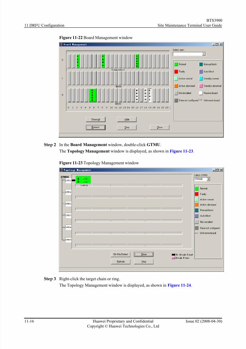
8/10/2019 BTS3900 Site Maintenance Terminal User Guide-(V300R008_02)
http://slidepdf.com/reader/full/bts3900-site-maintenance-terminal-user-guide-v300r00802 146/147
Figure 11-22 Board Management window
Step 2 In the Board Management window, double-click GTMU.
The Topology Management window is displayed, as shown in Figure 11-23.
Figure 11-23 Topology Management window
Step 3 Right-click the target chain or ring.
The Topology Management window is displayed, as shown in Figure 11-24.
11 DRFU Configuration
BTS3900
Site Maintenance Terminal User Guide
11-16 Huawei Proprietary and Confidential
Copyright © Huawei Technologies Co., Ltd
Issue 02 (2008-04-30)

8/10/2019 BTS3900 Site Maintenance Terminal User Guide-(V300R008_02)
http://slidepdf.com/reader/full/bts3900-site-maintenance-terminal-user-guide-v300r00802 147/147
Figure 11-24 Choosing Cancel Breakpoint
Step 4 Click Cancel Breakpoint
to cancel a breakpoint.
----End
BTS3900
Site Maintenance Terminal User Guide 11 DRFU Configuration