BTS3900 GSM Quick Installation Guide-(V300R008&R009_02)PDF
12
1 BTS3900 GSM V300R008&R009 Quick Installation Guide 900 mm 42 mm 450 mm 600 mm 420 mm ≥200 mm ≥800 mm Cabinet dimensions (height x width x depth): 900 mm x 600 mm x 450 mm Modules in the Cabinet 220 V cabinet -48 V cabinet +24 V cabinet Fan box BBU DCDU-01 BBU +24 V power equipment DCDU-01 BBU 220 V power equipment DCDU-01 RFU RFU RFU Issue: 02 Date: 2010-01-30 Safety Information Check the electrical connection of the device before operation and ensure that the device is reliably grounded. When working at a height, be cautious about falling objects. When operating the device, comply with the local safety regulations. The safety precautions provided in the documents are supplementary. You must comply with the local safety regulations. Power off the device before performing operations on the power supply equipment. High power radio-frequency signals are harmful to human body. Before installing or maintaining an antenna on a steel tower or mast with a large number of transmitter antennas, the operator should coordinate with all parties to ensure that the transmitter antennas are shut down. When handling optical fibers, do not stand close to, or look into the optical fiber outlet with unaided eyes. When working on batteries, take measures to prevent short circuits in the batteries and electrolyte spill/loss. The electrolyte may erode metal and boards, or even cause rust of the equipment or short circuits in the boards. When the cabinet is unpacked, it must be powered on in seven days. The maximum duration of the power-off state of the cabinet is 48 hours during maintenance. Clearance for the Cabinet Copyright © Huawei Technologies Co., Ltd. 2010. All rights reserved. Fan box Fan box
-
Upload
lubo-picturesmaker -
Category
Documents
-
view
124 -
download
23
description
BTS 3900 GSM QIG
Transcript of BTS3900 GSM Quick Installation Guide-(V300R008&R009_02)PDF

1
BTS3900 GSM V300R008&R009Quick Installation Guide
900 mm
42 mm
450 mm
600 mm420 mm
≥200 mm
≥800 mm
Cabinet dimensions (height x width x depth): 900 mm x 600 mm x 450 mm
Modules in the Cabinet220 V cabinet-48 V cabinet +24 V cabinet
Fan box
BBUDCDU-01
BBU
+24 V power equipment
DCDU-01BBU
220 V power equipment
DCDU-01
RFU RFU RFU
Issue: 02Date: 2010-01-30
Safety InformationCheck the electrical connection of the device before operation and ensure that the device is reliably grounded.
When working at a height, be cautious about falling objects.
When operating the device, comply with the local safety regulations. The safety precautions provided in the documents are supplementary. You must comply with the local safety regulations.
Power off the device before performing operations on the power supply equipment.
High power radio-frequency signals are harmful to human body. Before installing or maintaining an antenna on a steel tower or mast with a large number of transmitter antennas, the operator should coordinate with all parties to ensure that the transmitter antennas are shut down.
When handling optical fibers, do not stand close to, or look into the optical fiber outlet with unaided eyes.
When working on batteries, take measures to prevent short circuits in the batteries and electrolyte spill/loss. The electrolyte may erode metal and boards, or even cause rust of the equipment or short circuits in the boards.
When the cabinet is unpacked, it must be powered on in seven days. The maximum duration of the power-off state of the cabinet is 48 hours during maintenance.
Clearance for the Cabinet
Copyright © Huawei Technologies Co., Ltd. 2010. All rights reserved.
Fan box Fan box

2
Installing the Base on the Concrete Floor
2. Install the base.
1. Determine the installation position of the base and install expansion bolt assemblies.
Base
Ø1690°
52 mm to 60 mm
M12x60 boltSpring washerFlat washer
Expansion tubeDo not use a hammer drill to drill holes on the concrete pad through the holes on the base.
Insulating spacer(x2)
M12x60 bolt (x4)Spring washer 12
Flat washer 12Insulating washer
3. Adjust the base level and measure the resistance between the base and the bolts.
Adjust M12x30bolts (x4) on site.
Normal display: > 5 MΩ
The resistance between the base and the four expansion bolt assemblies should be respectively measured.
Level
Anchor hole
Concrete floor
Marking template
Installing the Base

3
Installing the Base on the ESD Floor
Concrete floor
2. Temporarily fasten the ESD floor and supports.
1. Determine the installation position of the base and drill holes on the ESD floor.
Support for the ESD floor
ESD floorFor details on how to drill holes and install expansion bolt assemblies on the concrete floor as shown in the figures ② and ③, see page 2.
When tightening the height locking bolts, you should tighten the bolts in the middle before tightening the bolts on both sides.
3. Install the base on the ESD floor.
M12x60 bolt
M12x70 bolt
Spring washer 12
Flat washer 12
M12x60 bolt (x4)Spring washer 12Flat washer 12Insulating washer
Insulating spacer (x2)
4. Adjust the base level and measure the resistance between the base and the bolts.
Do not use a hammer drill to drill holes on the concrete pad through the holes on the base.
(For details, see step 3 on page 2.)
For details, see step 1 on page 2.
Anchor hole
ESD floor
Marking template
Height locking bolt (both sides)
Mounting holes for the support
Height locking bolt (middle)

4
Installing the PGND Cables and Equipotential Cables
Installing the Cabinet and PGND Cables
Installing the PGND Cablesa
External ground barExternal ground bar
1. Install the PGND cable for the -48 V or 220 V cabinet.
2. Install the PGND cable for the +24 V cabinet.
If the cabinet is installed with the power subrack before delivery, you should remove the power subrack from the cabinet and also the power cable between the power subrack and the DCDU-01 and PGND cable for the power subrack before tightening bolts. After the cabinet is installed, install the power subrack, related power cable, and related PGND cable.
The cabinet door can be removed before the cabinet is installed for easy operations.
M12x50 bolt (x2)
Power subrack
Installing the Cabinet

5
Installing the Equipotential Cables b
side-by-side mode stack mode
M6
M6
M6
M6
BBU
DCDU-01 DCDU-01
BBU
DCDU-01
DCDU-01
RFU RFU RFU
RFU
Remove the cover plate.
The EquipotentialCables need to be installed only in the stacked +24 V cabinet scenario.
The cable installations in the stacked +24 V cabinet scenario and in the stacked -48 V cabinet scenario are similar, except that the equipotential cable needs to be installed on the left of the cabinet in the stacked +24 V cabinet scenario.
Fan box
Fan boxFan boxFan box

6
Installing the Power Cable for the -48 V Cabineta
Installing the Power Cable for the +24 V Cabinetb
DCDU-01
Free
PSU
+24 V cabinet
-48 V cabinet
When arranging for the power cable on site, do not expose the metal wire.
BBUFREE
BBUDCDU-01
RFU
RFU
Plastic cover plate
RTN(+)
The method for installing the power cable for cabinets installed side-by-side or power cable for stacked cabinets is the same as that for installing the power cable for a single cabinet.
NEG(-)
Installing the Input Power Cable
Installing Cables
In this document, the cable color and equipment appearance is for reference only. The actual cables and equipment may differ from what are shown in the figures.
Attach labels before routing cables.When cutting the BTS3900 input power cable, reserve an extra length of 300 mm. Add an OT terminal to the cable on site.
+-
Fan box
Fan box

7
Installing the Input Power CableInstalling the Power Cable for the 220 V Cabinetc
Installing Transmission Cables
PSU
BBU
RFU
DCDU-01
PMU
220 V AC single-phase input
110 V AC dual-live-wire input
220 V AC three-phase input
Short-circuiting cable for live wires (brown)
Short-circuiting cable for neutral wires (blue)
220 V cabinet
BBUGTMU
UPEU
BBU
E1/T1FE0
1. Installing the E1 Cable 2. Installing the FE Cable
Based on transmission mode, only one type of E1/T1 cable needs to be installed. Alternatively, FE cable is installed if FE transmission mode is used.
Ensure that both ends of the E1 cable are disconnected. Then, weld connectors to the bare wires at one end of the E1 cable all at once.
Fan box

8
Installing RF Cables
Attach color rings by referring to the following table.
Install the cables in the sequence from top to bottom and from both sides to middle.
Diversity antenna: one white ring and one blue ring
Main antenna: one white ring and two blue rings
3
Diversity antenna: one white ring and one yellow ring
Main antenna: one white ring and two yellow rings
2
Diversity antenna: one white ring and one red ring
Main antenna: one white ring and two red rings
1System 2
Diversity antenna: one blue ring
Main antenna: two blue rings3
Diversity antenna: one yellow ring
Main antenna: two yellow rings2
Diversity antenna: one red ring
Main antenna: two red rings1System 1
Color RingSectorSystemANT_TX/RXA
BBU
DCDU-01
RFU
ANT_TX/RXB
ANT_TX/RXA
ANT_TX/RXA
BBU
DCDU-01
DCDU-01
RFU
RFU
ANT_TX/RXB
ANT_TX/RXB
A single cabinet
Stacked cabinets
If main and diversity are not distinguished, the RF signals transmitted from the left RF unit are regarded as the main signals by default, and the RF signals transmitted from the right RF unit are regarded as the diversity signals.
If an antenna system serves six sectors, the colors of the rings for sectors 4, 5, and 6 are purple, orange, and green respectively.
If the inter-RFU RF signal cables are installed before the cabinet is delivered, only the cables on the ANT_TX/RXA ports need to be installed.
The methods for routing RF jumpers in a single cabinet and in cabinets installed side-by-side are the same. The cover plate of the upper cabinet must be removed before the RF jumpers are installed in stacked cabinets.
Remove the cover plate.
Fan box
Fan box
Fan box
9
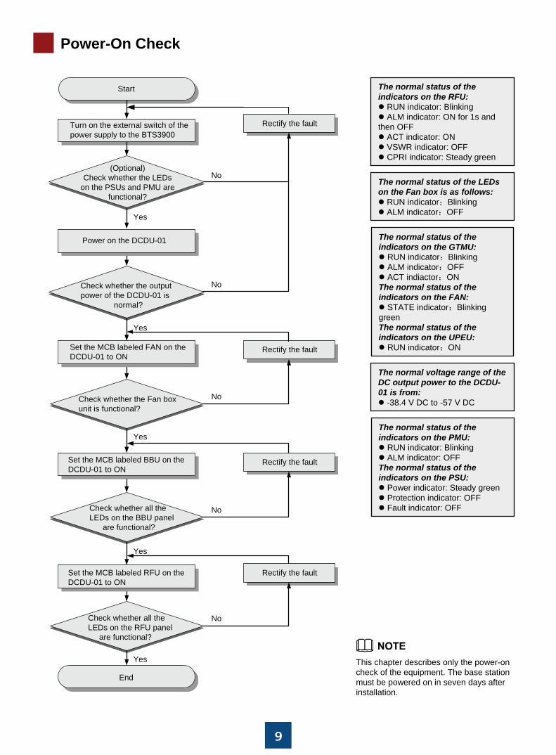
Power-On Check
This chapter describes only the power-on check of the equipment. The base station must be powered on in seven days after installation.
The normal status of the indicators on the PMU:
RUN indicator: BlinkingALM indicator: OFF
The normal status of the indicators on the PSU:
Power indicator: Steady greenProtection indicator: OFFFault indicator: OFF
The normal status of the indicators on the GTMU:
RUN indicator:BlinkingALM indicator:OFFACT indiactor:ON
The normal status of the indicators on the FAN:
STATE indicator:Blinking greenThe normal status of the indicators on the UPEU:
RUN indicator:ON
The normal voltage range of the DC output power to the DCDU-01 is from:
-38.4 V DC to -57 V DC
The normal status of the indicators on the RFU:
RUN indicator: BlinkingALM indicator: ON for 1s and
then OFFACT indicator: ONVSWR indicator: OFFCPRI indicator: Steady green
The normal status of the LEDson the Fan box is as follows:
RUN indicator:BlinkingALM indicator:OFF
Turn on the external switch of thepower supply to the BTS3900
Start
Rectify the fault
Rectify the fault
Rectify the fault
Rectify the fault
No
No
No
No
No
Yes
Yes
Yes
Yes
Yes
End
Power on the DCDU-01
Check whether the outputpower of the DCDU-01 is normal?
(Optional)Check whether the LEDs
on the PSUs and PMU arefunctional?
Set the MCB labeled FAN on theDCDU-01 to ON
Check whether the Fan boxunit is functional?
Set the MCB labeled BBU on theDCDU-01 to ON
Set the MCB labeled RFU on theDCDU-01 to ON
Check whether all theLEDs on the BBU panel are functional?
Check whether all theLEDs on the RFU panel are functional?

10
AppendixRemoving the CPRI Cables
Product 4 Product 5
Product 3 Product 2 Product 1
Waterproofing Outdoor Cables
1. Wrap three layers of waterproof tapes.
2. Wrap three layers of insulating tapes.
Push Push Push
Push Push
PullPull
Pull
Pull
Cable tie
Waterproof tape
Insulating tape
The waterproof tape should be wrapped for an extra length of 20 mm away from the connectors at both ends.
The tapes should be wrapped around the connector from the lower part to the upper part. When wrapped for another layer, the tapes may not be cut.
When wrapping the waterproof tape, ensure that the upper layer of the tape covers at least 50% of the lower layer.
The insulating tape should be wrapped for an extra length of 20 mm away from the waterproof tapes at both ends.
Extend the tape.
Pull

11
Pin Assignment
TX4
TX3
TX2
TX1
RX4
RX3
RX2
Green
Gray
White
Brown
White
Green
Blue1
Orange23
Red22Twisted
pair Blue21
White20
Twisted pair Red26
Twisted pair Red24
25
White
Orange
White
Wire Color
6
Twisted pair
7
8
Twisted pair
19
Twisted pair
5
4
3
2
X1
Twisted pair
Twisted pair
Wire Type
RX1
Label
TX4
TX3
TX2
TX1
RX4
RX3
RX2
Tip
Tip
Ring
Tip
Ring
Tip
Tip1
Tip23
Ring224
Tip21
Ring20
8Ring26
6Ring24
25
Ring
Tip
Ring
Wire Type
6
77
8
219
55
4
3
2
X1
3
1
Coaxial SN
RX1
Label
1. Pin assignments for the wires of the 75-ohm E1 coaxial cable
2. Pin assignments for the wires of the 120-ohm E1 twisted pair cable
Green/whiteBrown/whiteGray/whiteBlue/redOrange/redGreen/red
Orange/whiteBlue/white

12
HUAWEI TECHNOLOGIES CO., LTD.Huawei Industrial Base Bantian Longgang
Shenzhen 518129People’s Republic of China
www.huawei.com