BTR 30 TURF ROLLER - Brouwer Turf :: Brouwer Turf Turf ... BTR 30 – TURF ROLLER CONTENTS SECTION 1...
34
00000000000000 BTR 30 TURF ROLLER OPERATOR’S MANUAL & PARTS LIST CURRENT FROM SERIAL NO. 610 Kesmac Inc. 23324 Woodbine Avenue, Keswick Ontario Canada L4P 3E9 Tel (905) 476-6222 Fax (905) 476-6744 Web Site www.brouwerturf.com Email [email protected]
Transcript of BTR 30 TURF ROLLER - Brouwer Turf :: Brouwer Turf Turf ... BTR 30 – TURF ROLLER CONTENTS SECTION 1...
00000000000000
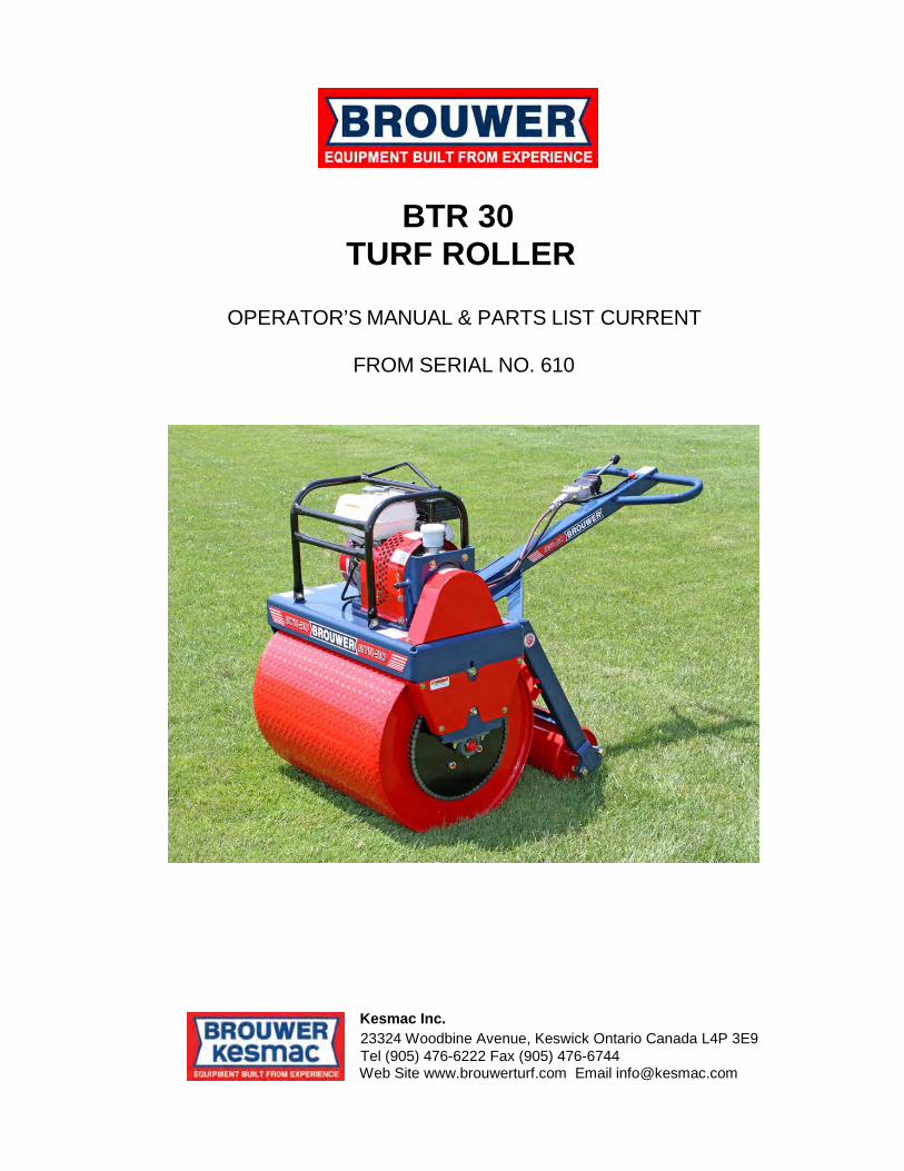
BTR 30 TURF ROLLER
OPERATOR’S MANUAL & PARTS LIST CURRENT
FROM SERIAL NO. 610
Kesmac Inc. 23324 Woodbine Avenue, Keswick Ontario Canada L4P 3E9 Tel (905) 476-6222 Fax (905) 476-6744 Web Site www.brouwerturf.com Email [email protected]

STATEMENT OF LIMITED WARRANTY ________________________________________________________________________
Kesmac and Brouwer Turf warrants its full line of equipment to be free from defects in material and factory workmanship for a
period of 12 months. This warranty begins on the date of sale or use of the equipment to the original purchaser. This statement does not extend or limit engine, tractor or component warranties in which the engine, tractor or component manufacturers may carry extended time periods up to 24 months. Engine, tractor or component warranty claims will be subject to the engine, tractor or components manufacturer’s approval. Replacement Parts carry a 90 day replacement warranty and are reimbursed to the dealer. All electrical and hydraulic parts are limited by this policy and will only be covered upon approval by the service department after inspection of the part. The installation and removal of a part will automatically place that part under the replacement parts warranty. This warranty is limited exclusively to equipment or accessories manufactured or supplied by Kesmac and Brouwer Turf and are subject to the inspection and analysis by the company to conclusively identify the nature and cause of failure. PRODUCT REGISTRATION FORM must be completely filled out, signed by the customer at the original date of installation, and returned to Kesmac and Brouwer Turf before any claims will be considered. Kesmac and Brouwer Turf reserves the right to incorporate improvements in material and design of its products without notice and is not obligated to make the same improvements to equipment previously manufactured. Kesmac and Brouwer Turf is not obliged under any warranty policy different from the Kesmac Brouwer Turf warranty policy as published above.
KESMAC AND BROUWER TURF RESPONSIBILITES Kesmac and Brouwer Turf ‘s obligation under the terms of this warranty is limited to the repair, replacement or credit, at its option, of the equipment, parts or supply items that conform to its warranty. Kesmac and Brouwer Turf will pay for the parts and the cost of surface transportation for the parts that conform to this warranty.
DEALER’S RESPONSIBILITIES 1. Only factory-trained service or approved personnel will be permitted to perform warranty service on Kesmac and Brouwer Turf equipment. 2. All major warranty claims exceeding $650.00 (in total including parts and labour) must be authorized by Kesmac and Brouwer Turf before work is performed. 3. All replacement parts used in warranty situations must be furnished by Kesmac and Brouwer Turf or approved by Kesmac and Brouwer Turf personnel. The use of non-recommended oil could nullify warranty.
OWNERS RESPONSIBILITIES The owner is obligated to operate and maintain the equipment in accordance with the recommendations published by Kesmac and Brouwer Turf in the owners/operators manual for the unit. The owner is responsible for the costs associated with such maintenance and operating adjustments that may be required on a regularly scheduled basis. Where applicable the owner is responsible for transportation to and from the dealership or service calls made by the dealer.
CONDITIONS THAT VOID WARRANTY This warranty shall not apply to equipment which:
• 1. Has had repairs or modifications not authorized by Kesmac and Brouwer Turf. • 2. Has been subject to abuse, improper maintenance, or improper application. • 3. Has been modified from original equipment specifications.
WARRANTY EXCEPTIONS
This warranty does not apply to the following items: • 1. Wear items including blades, cutting edges, cutting arms, spark plugs, belts, filters, bearings, sprockets, chains, tires,
light bulbs, lubricants and fluids etc. Cost of normal maintenance including replacement of service items. • 2. Damages to engine/drive systems caused by lack of/or improper lubricants and/or fluids. • 3. Damages arising from accident, misuse or neglect. • 4. Damages to engine/drive systems caused by improper operation and/or maintenance. • 5. Kesmac and Brouwer Turf will not be liable for any incidental or consequential damage or injuries, including but not limited to
loss of profits, loss of crops, rental of substitute equipment, or other commercial loss or for damage to the equipment in which the Company Product is installed.
FREIGHT CARRIER DAMAGE
July 2010
Claims for equipment damaged in transit should be referred to the freight carrier. Visible damage should be reported immediately and concealed damage as soon as possible, in accordance with freight carrier regulations.


BROUWER BTR 30 – TURF ROLLER
CONTENTS
SECTION 1 – Operators Manual
General Safety 1 Safety Precautions 2
Decals 3 Operating Instructions Front & Rear Rollers 4 Engine 5 Controls 5 Engine Speed Control 6 Maintenance Engine 6 Forward / Reverse Adjustment 7 Drive Chain 8 Operating Handle Storage 9 Lubrication 10 Specifications 11
SECTION 2 – Parts List Frame & Rollers Assembly 1 Drive Sprockets & Chains 3 Controls 5 Engine & Transmission 7 Power Unit Protection Cage 9 Dead-Man Switch Assembly 9
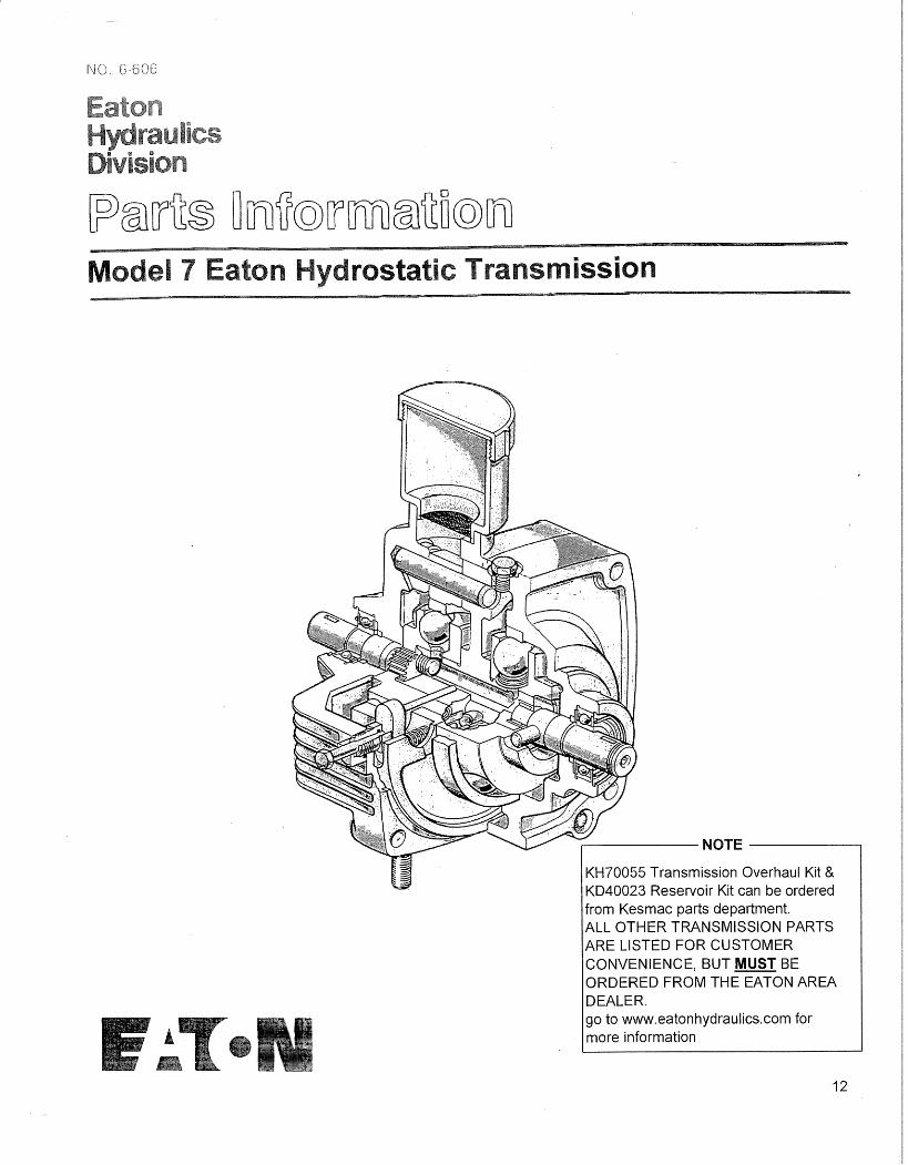
Eaton Hydrostat Transmission 12
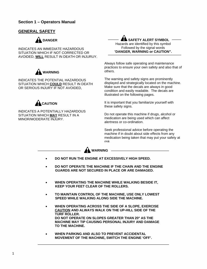
Section 1 – Operators Manual GENERAL SAFETY
SAFETY ALERT SYMBOL Hazards are identified by this symbol
Followed by the signal words “DANGER, WARNING or CAUTION”.
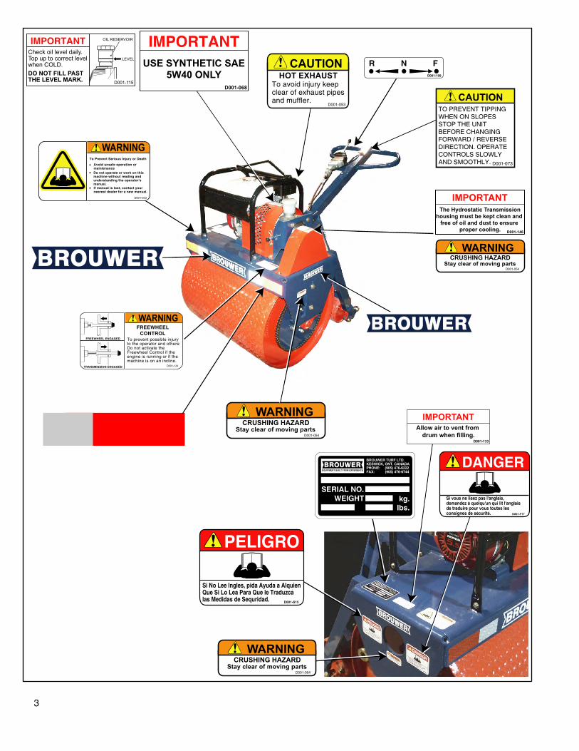
Always follow safe operating and maintenance practices to ensure your own safety and also that of others. The warning and safety signs are prominently displayed and strategically located on the machine. Make sure that the decals are always in good condition and easily readable. The decals are illustrated on the following pages. It is important that you familiarize yourself with these safety signs. Do not operate this machine if drugs, alcohol or medication are being used which can affect alertness or co-ordination. Seek professional advice before operating the machine if in doubt about side effects from any medication being taken that may put your safety at risk.
DANGER INDICATES AN IMMEDIATE HAZARDOUS SITUATION WHICH IF NOT CORRECTED OR AVOIDED, WILL RESULT IN DEATH OR INJURUY. WARNING INDICATES THE POTENTIAL HAZARDOUS SITUATION WHICH COULD RESULT IN DEATH OR SERIOUS INJURY IF NOT AVOIDED, CAUTION INDICATES A POTENTIALLY HAZARDOUS SITUATION WHICH MAY RESULT IN A MINOR/MODERATE INJURY.
WARNING
• DO NOT RUN THE ENGINE AT EXCESSIVELY HIGH SPEED. • DO NOT OPERATE THE MACHINE IF THE CHAIN AND THE ENGINE GUARDS ARE NOT SECURED IN PLACE OR ARE DAMAGED.
• WHEN OPERATING THE MACHINE WHILE WALKING BESIDE IT, KEEP YOUR FEET CLEAR OF THE ROLLERS. • TO MAINTAIN CONTROL OF THE MACHINE, USE ONLY LOWEST SPEED WHILE WALKING ALONG SIDE THE MACHINE. • WHEN OPERATING ACROSS THE SIDE OF A SLOPE, EXERCISE CAUTION AND ALWAYS WALK ON THE UP-HILL SIDE OF THE TURF ROLLER. DO NOT OPERATE ON SLOPES GREATER THAN 20° AS THE MACHINE MAY TIP CAUSING PERSONAL INJURY AND DAMAGE TO THE MACHINE. • WHEN PARKING AND ALSO TO PREVENT ACCIDENTAL MOVEMENT OF THE MACHINE, SWITCH THE ENGINE ‘OFF’.
1
BROUWER BTR 30 TURF ROLLER
SAFETY PRECAUTIONS
It is important that the operator(s) of this machine follows all the recommended operating procedures and service schedules that help ensure the safety of the machine, the operators and bystanders. It is not possible to list all possible situations that may affect the safety of the machine or the operators, therefore it is not possible to identify all precautions. The Owners/Operator must assume responsibility for their own safety, the safety of others and of the machine by reading this manual, fully understanding the operation of all controls, following correct operating procedures, and aware of any potential hazards. IF YOU DO NOT UNDERSTAND – ASK.
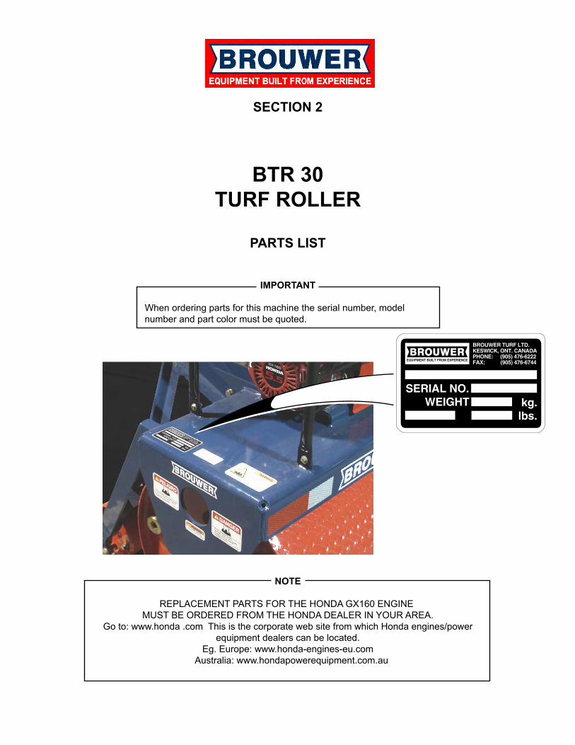
IMPORTANT Use only genuine Brouwer Parts. Parts that are not supplied by Brouwer may not meet Brouwer specifications or standards of manufacture. The use of non-approved parts may result in component failure and possibly an accident and injury to the operator and others.
CAUTION Allow sufficient time for the engine to cool down before any service work. Failure to observe this may result in burns from hot exhaust components
IF YOU DO NOT UNDERSTAND ANY PART OF THIS MANUAL (OR OTHER MANUALS SUPPLIED WITH THIS MACHINE) CONTACT YOUR SUPERVISOR, YOUR DEALER OR THE MAUFACTURER FOR CLARIFICATION.
NOTE Reference to RIGHT or LEFT are to be interpreted as viewed from the operating position looking forward.
The Brouwer BTR 30 Turf Roller is designed for safe efficient operation. It must not be used for any other purpose that that for which it was designed. Prior to shipping from the factory the machine is inspected to insure that all guards/shields and warning/operating decals are correctly positioned and secured. Before operating the machine the operator must check that all of the above items are correctly located. This machine must not be used if any guard/shield or warning/operating decals are missing, damaged or incorrectly located. The operator must read and understand this manual before operating the machine.
2
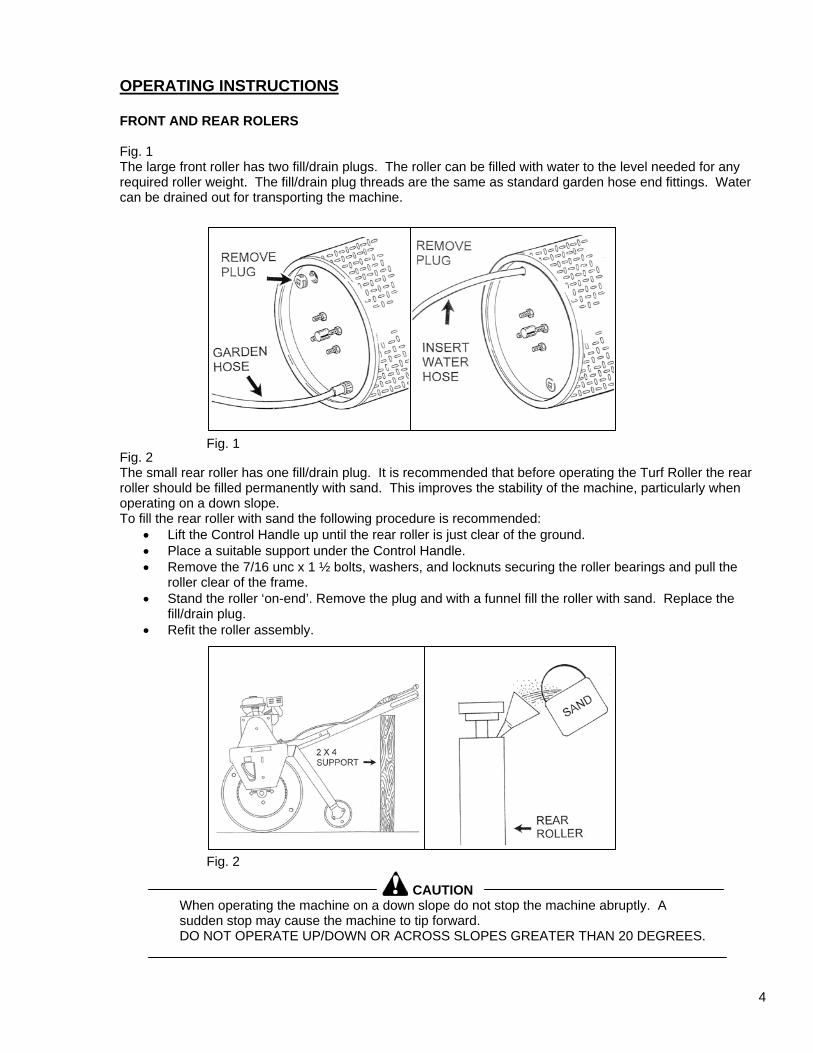
OPERATING INSTRUCTIONS FRONT AND REAR ROLERS Fig. 1 The large front roller has two fill/drain plugs. The roller can be filled with water to the level needed for any required roller weight. The fill/drain plug threads are the same as standard garden hose end fittings. Water can be drained out for transporting the machine.
Fig. 1 Fig. 2 The small rear roller has one fill/drain plug. It is recommended that before operating the Turf Roller the rear roller should be filled permanently with sand. This improves the stability of the machine, particularly when operating on a down slope. To fill the rear roller with sand the following procedure is recommended:
• Lift the Control Handle up until the rear roller is just clear of the ground. • Place a suitable support under the Control Handle. • Remove the 7/16 unc x 1 ½ bolts, washers, and locknuts securing the roller bearings and pull the
roller clear of the frame. • Stand the roller ‘on-end’. Remove the plug and with a funnel fill the roller with sand. Replace the
fill/drain plug. • Refit the roller assembly.
Fig. 2
CAUTION When operating the machine on a down slope do not stop the machine abruptly. A sudden stop may cause the machine to tip forward. DO NOT OPERATE UP/DOWN OR ACROSS SLOPES GREATER THAN 20 DEGREES.
4
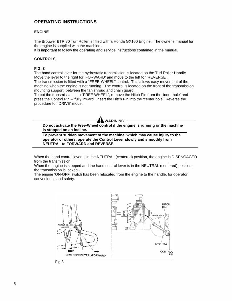
OPERATING INSTRUCTIONS ENGINE The Brouwer BTR 30 Turf Roller is fitted with a Honda GX160 Engine. The owner’s manual for the engine is supplied with the machine. It is important to follow the operating and service instructions contained in the manual. CONTROLS FIG. 3 The hand control lever for the hydrostatic transmission is located on the Turf Roller Handle. Move the lever to the right for ‘FORWARD’ and move to the left for ‘REVERSE’. The transmission is fitted with a “FREE-WHEEL” control. This allows easy movement of the machine when the engine is not running. The control is located on the front of the transmission mounting support, between the fan shroud and chain guard. To put the transmission into “FREE WHEEL”, remove the Hitch Pin from the ‘inner hole’ and press the Control Pin – ‘fully inward’, insert the Hitch Pin into the ‘center hole’. Reverse the procedure for ‘DRIVE’ mode.
WARINING Do not activate the Free-Wheel control if the engine is running or the machine is stopped on an incline. To prevent sudden movement of the machine, which may cause injury to the operator or others, operate the Control Lever slowly and smoothly from NEUTRAL to FORWARD and REVERSE.
When the hand control lever is in the NEUTRAL (centered) position, the engine is DISENGAGED from the transmission. When the engine is stopped and the hand control lever is in the NEUTRAL (centered) position, the transmission is locked. The engine ’ON-OFF’ switch has been relocated from the engine to the handle, for operator convenience and safety.
Fig.3
5
OPERATING INSTRUCTIONS ENGINE SPEED CONTROL Refer to the Honda Engine Owners manual for the instructions on setting the engine speed. Set the engine speed control to give two-thirds throttle opening.
IMPORTANT Do not run the engine at low speed as this may cause damage to the transmission due to inadequate cooling air flow.
WARNING When the engine is running and the hand control lever is in the NEUTRAL (centered) position, the transmission is in “FREE-WHEEL” mode and if the machine is left unattended it can move/roll and cause personal injury or machine damage.
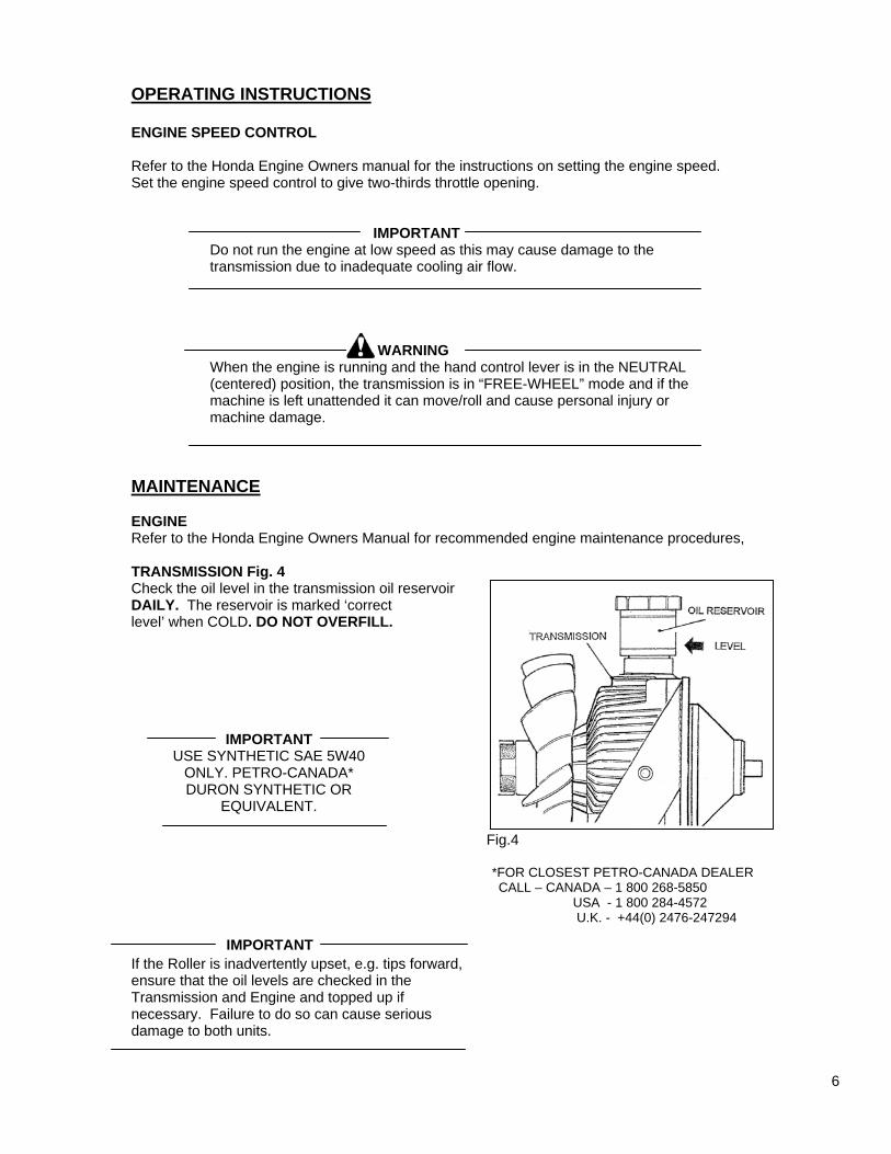
MAINTENANCE ENGINE Refer to the Honda Engine Owners Manual for recommended engine maintenance procedures, TRANSMISSION Fig. 4 Check the oil level in the transmission oil reservoir DAILY. The reservoir is marked ‘correct level’ when COLD. DO NOT OVERFILL.
IMPORTANT
USE SYNTHETIC SAE 5W40 ONLY. PETRO-CANADA* DURON SYNTHETIC OR
EQUIVALENT. Fig.4
*FOR CLOSEST PETRO-CANADA DEALER CALL – CANADA – 1 800 268-5850 USA - 1 800 284-4572 U.K. - +44(0) 2476-247294
If the Roller is inadvertently upset, e.g. tips forward, ensure that the oil levels are checked in the Transmission and Engine and topped up if necessary. Failure to do so can cause serious damage to both units.
IMPORTANT
6
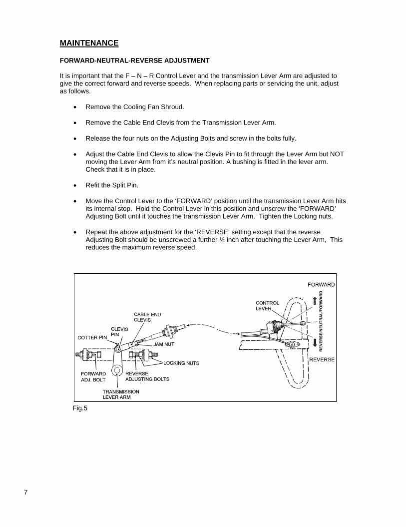
MAINTENANCE FORWARD-NEUTRAL-REVERSE ADJUSTMENT It is important that the F – N – R Control Lever and the transmission Lever Arm are adjusted to give the correct forward and reverse speeds. When replacing parts or servicing the unit, adjust as follows.
• Remove the Cooling Fan Shroud. • Remove the Cable End Clevis from the Transmission Lever Arm. • Release the four nuts on the Adjusting Bolts and screw in the bolts fully. • Adjust the Cable End Clevis to allow the Clevis Pin to fit through the Lever Arm but NOT
moving the Lever Arm from it’s neutral position. A bushing is fitted in the lever arm. Check that it is in place.
• Refit the Split Pin. • Move the Control Lever to the ‘FORWARD’ position until the transmission Lever Arm hits
its internal stop. Hold the Control Lever in this position and unscrew the ‘FORWARD’ Adjusting Bolt until it touches the transmission Lever Arm. Tighten the Locking nuts.
• Repeat the above adjustment for the ‘REVERSE’ setting except that the reverse
Adjusting Bolt should be unscrewed a further ¼ inch after touching the Lever Arm, This reduces the maximum reverse speed.
Fig.5
7
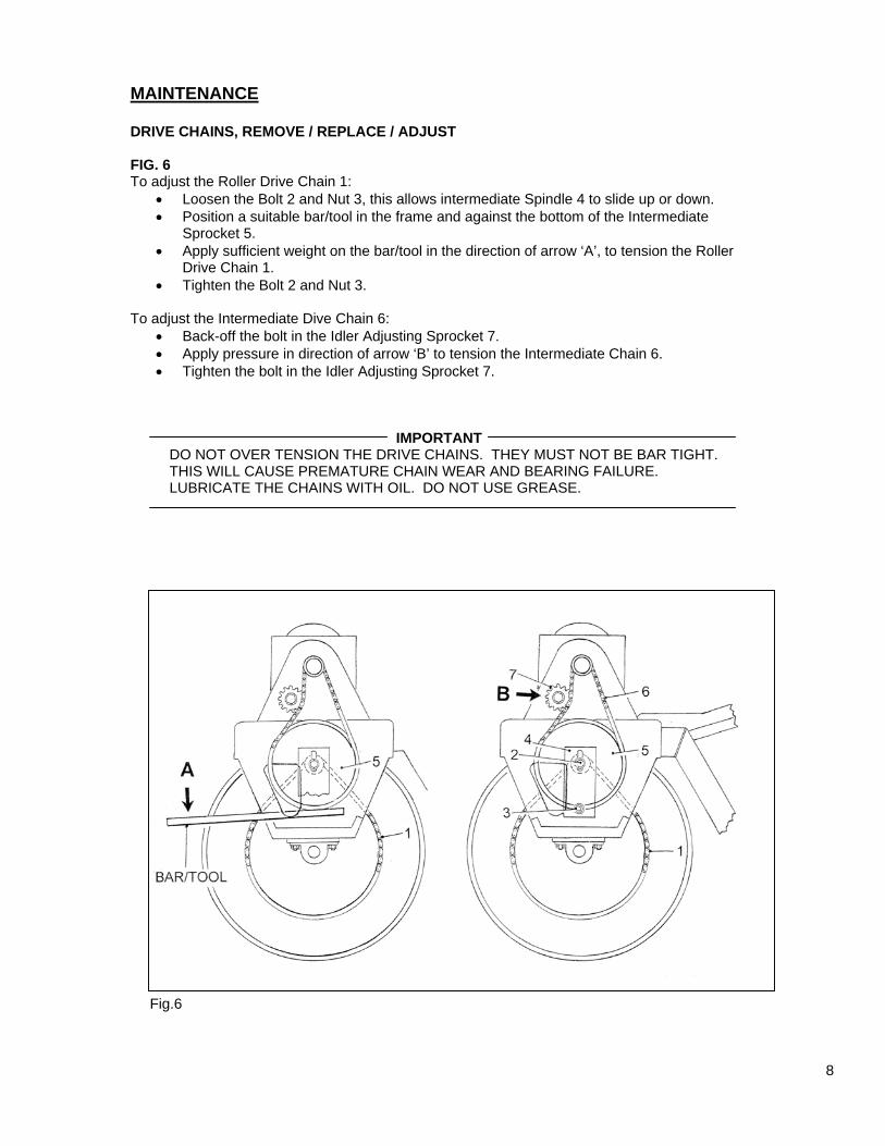
MAINTENANCE DRIVE CHAINS, REMOVE / REPLACE / ADJUST FIG. 6 To adjust the Roller Drive Chain 1:
• Loosen the Bolt 2 and Nut 3, this allows intermediate Spindle 4 to slide up or down. • Position a suitable bar/tool in the frame and against the bottom of the Intermediate
Sprocket 5. • Apply sufficient weight on the bar/tool in the direction of arrow ‘A’, to tension the Roller
Drive Chain 1. • Tighten the Bolt 2 and Nut 3.
To adjust the Intermediate Dive Chain 6:
• Back-off the bolt in the Idler Adjusting Sprocket 7. • Apply pressure in direction of arrow ‘B’ to tension the Intermediate Chain 6. • Tighten the bolt in the Idler Adjusting Sprocket 7.
IMPORTANT
DO NOT OVER TENSION THE DRIVE CHAINS. THEY MUST NOT BE BAR TIGHT. THIS WILL CAUSE PREMATURE CHAIN WEAR AND BEARING FAILURE. LUBRICATE THE CHAINS WITH OIL. DO NOT USE GREASE.
Fig.6
8
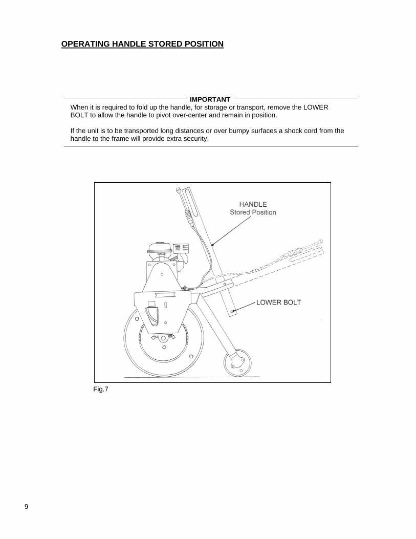
OPERATING HANDLE STORED POSITION
IMPORTANT When it is required to fold up the handle, for storage or transport, remove the LOWER BOLT to allow the handle to pivot over-center and remain in position. If the unit is to be transported long distances or over bumpy surfaces a shock cord from the handle to the frame will provide extra security. Fig.7
9
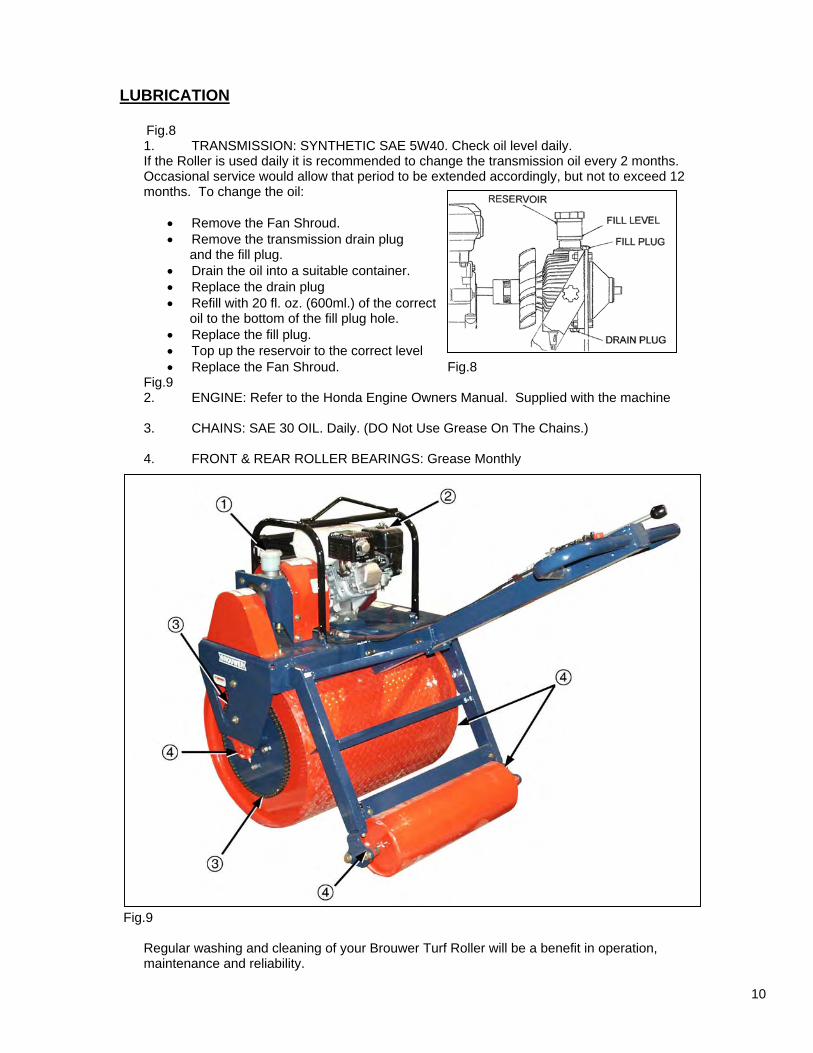
LUBRICATION Fig.8
1. TRANSMISSION: SYNTHETIC SAE 5W40. Check oil level daily. If the Roller is used daily it is recommended to change the transmission oil every 2 months. Occasional service would allow that period to be extended accordingly, but not to exceed 12 months. To change the oil:
• Remove the Fan Shroud. • Remove the transmission drain plug and the fill plug. • Drain the oil into a suitable container. • Replace the drain plug • Refill with 20 fl. oz. (600ml.) of the correct oil to the bottom of the fill plug hole. • Replace the fill plug. • Top up the reservoir to the correct level • Replace the Fan Shroud. Fig.8
Fig.9 2. ENGINE: Refer to the Honda Engine Owners Manual. Supplied with the machine 3. CHAINS: SAE 30 OIL. Daily. (DO Not Use Grease On The Chains.) 4. FRONT & REAR ROLLER BEARINGS: Grease Monthly
Fig.9
Regular washing and cleaning of your Brouwer Turf Roller will be a benefit in operation, maintenance and reliability.
10
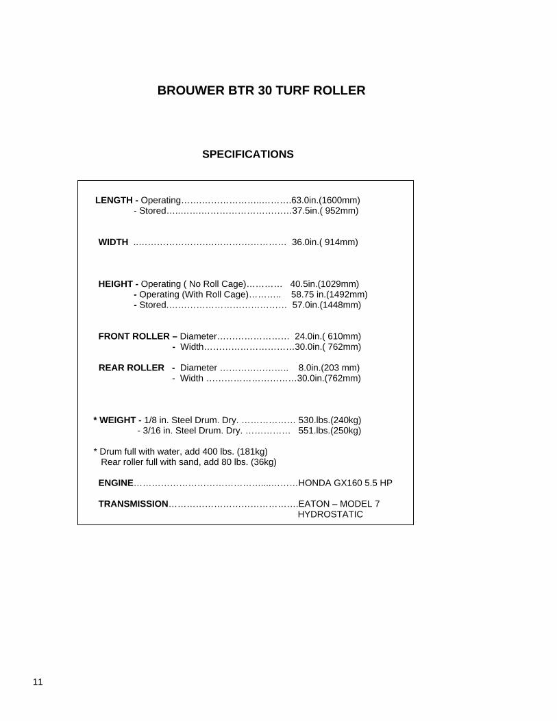
BROUWER BTR 30 TURF ROLLER
SPECIFICATIONS
LENGTH - Operating…….………………..……….63.0in.(1600mm) - Stored…..…….…………………………37.5in.( 952mm) WIDTH ..…………………….…………………… 36.0in.( 914mm) HEIGHT - Operating ( No Roll Cage)………… 40.5in.(1029mm) - Operating (With Roll Cage)……….. 58.75 in.(1492mm) - Stored.………………………………… 57.0in.(1448mm) FRONT ROLLER – Diameter…………………… 24.0in.( 610mm)
- Width…………………………30.0in.( 762mm)
REAR ROLLER - Diameter ………………….. 8.0in.(203 mm) - Width …………………………30.0in.(762mm)
* WEIGHT - 1/8 in. Steel Drum. Dry. ……………… 530.lbs.(240kg) - 3/16 in. Steel Drum. Dry. …………… 551.lbs.(250kg)
* Drum full with water, add 400 lbs. (181kg) Rear roller full with sand, add 80 lbs. (36kg) ENGINE……………………………………....………HONDA GX160 5.5 HP TRANSMISSION…………………………………….EATON – MODEL 7 HYDROSTATIC
11
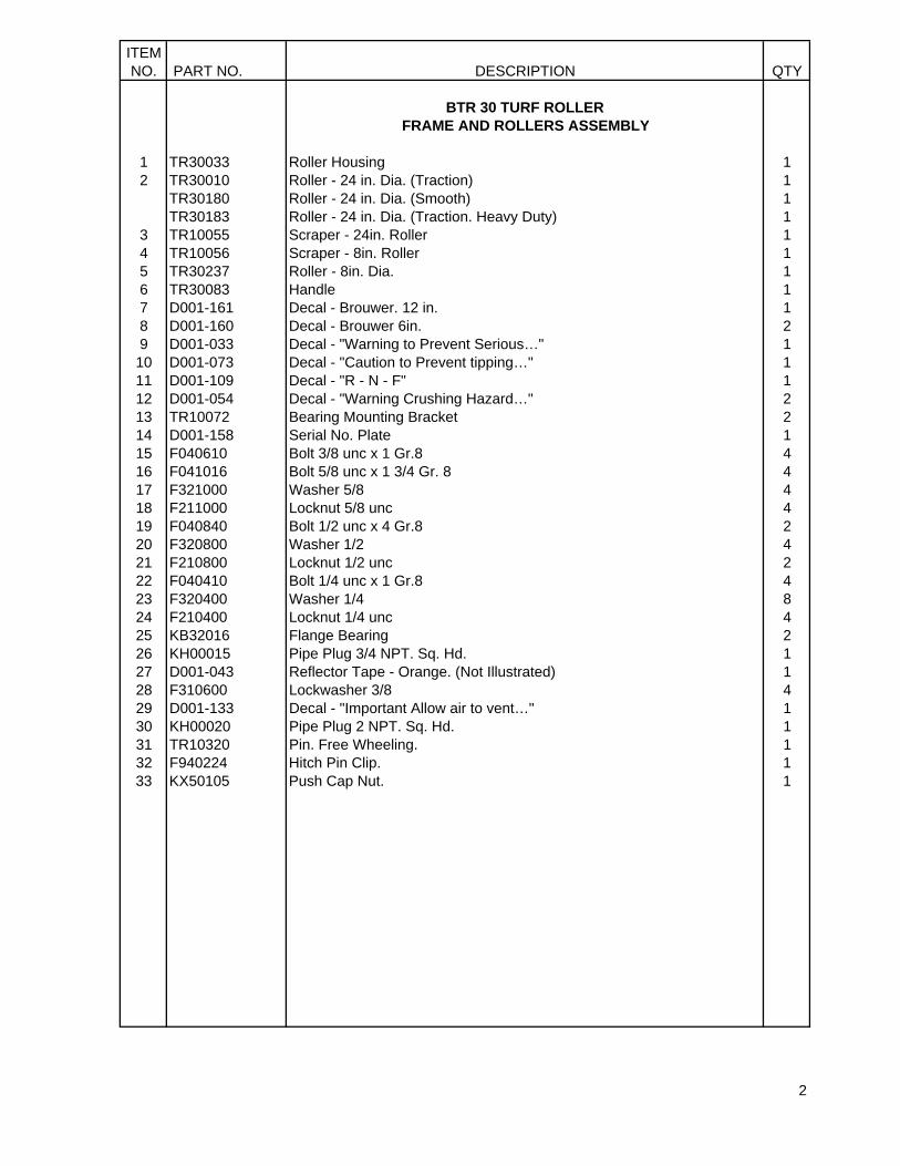
ITEMNO. PART NO. DESCRIPTION QTY
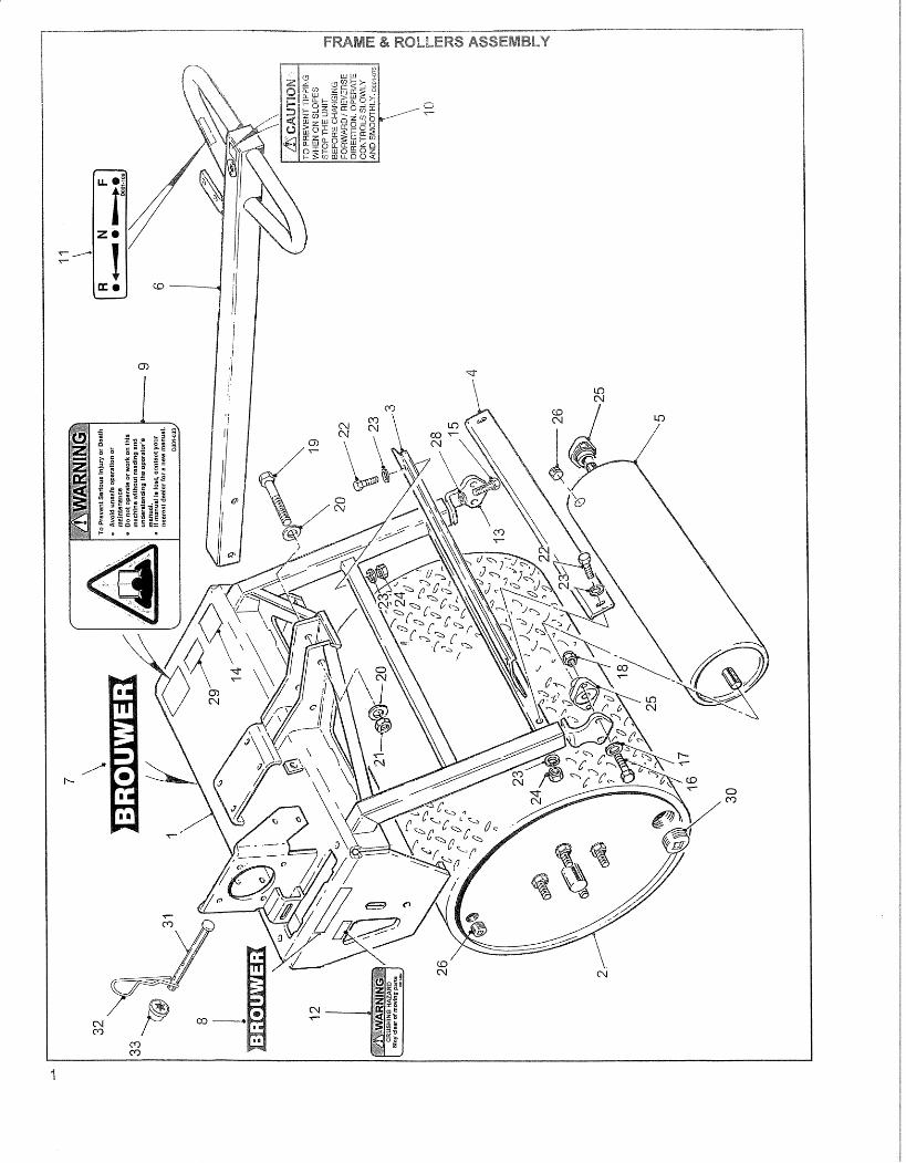
BTR 30 TURF ROLLER FRAME AND ROLLERS ASSEMBLY
1 TR30033 Roller Housing 12 TR30010 Roller - 24 in. Dia. (Traction) 1 TR30180 Roller - 24 in. Dia. (Smooth) 1 TR30183 Roller - 24 in. Dia. (Traction. Heavy Duty) 13 TR10055 Scraper - 24in. Roller 14 TR10056 Scraper - 8in. Roller 15 TR30237 Roller - 8in. Dia. 16 TR30083 Handle 17 D001-161 Decal - Brouwer. 12 in. 18 D001-160 Decal - Brouwer 6in. 29 D001-033 Decal - "Warning to Prevent Serious…" 110 D001-073 Decal - "Caution to Prevent tipping…" 111 D001-109 Decal - "R - N - F" 112 D001-054 Decal - "Warning Crushing Hazard…" 213 TR10072 Bearing Mounting Bracket 214 D001-158 Serial No. Plate 115 F040610 Bolt 3/8 unc x 1 Gr.8 416 F041016 Bolt 5/8 unc x 1 3/4 Gr. 8 417 F321000 Washer 5/8 418 F211000 Locknut 5/8 unc 419 F040840 Bolt 1/2 unc x 4 Gr.8 220 F320800 Washer 1/2 421 F210800 Locknut 1/2 unc 222 F040410 Bolt 1/4 unc x 1 Gr.8 423 F320400 Washer 1/4 824 F210400 Locknut 1/4 unc 425 KB32016 Flange Bearing 226 KH00015 Pipe Plug 3/4 NPT. Sq. Hd. 127 D001-043 Reflector Tape - Orange. (Not Illustrated) 128 F310600 Lockwasher 3/8 429 D001-133 Decal - "Important Allow air to vent…" 130 KH00020 Pipe Plug 2 NPT. Sq. Hd. 131 TR10320 Pin. Free Wheeling. 132 F940224 Hitch Pin Clip. 133 KX50105 Push Cap Nut. 1
2
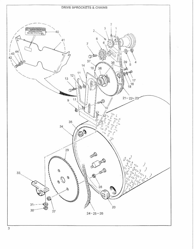
ITEMNO. PART NO. DESCRIPTION QTY
BTR 30 TURF ROLLER DRIVE SPROCKETS & CHAINS
1 F900404 Woodruff Key 1/8 z 1/2 12 F140402 Set Screw 1/4 unc Soc. Hd. 23 TR10029 Sprocket Transmission Shaft 14 F211000 Locknut 5/8 unc 15 F321000 Washer 5/8 26 TR10089 Spacer 17 F041020 Bolt 5/8 unc x 2 Gr.8 18 KD70003 Sprocket 18 T c/w Bearing 19 F210700 Locknut 7/16 unc 110 F020712 Carriage Bolt 7/16 unc x 1 1/4 111 F320700 Washer 7/16 112 F310700 Lockwasher 7/16 113 F040720 Bolt 7/16 unc x 2 Gr.8 114 TR30067 Sprocket Spindle 115 KB50003 Bearing 116 F310400 Lockwasher 1/4 117 F040406 Bolt 1/4 unc x 3/4 Gr.8 118 TR10005 Retaining Washer 119 KB11623 Bearing 120 KH00020 Pipe Plug 2 NPT. Sq. Hd. 121 KD71000 Chain Half Link #40 (if required) 122 KD71001 Chain Connecting Link #40 123 TR10096 Chain #40 Intermediate Sprocket to Transmission 39 1/2 in. 124 KD41001 Chain Half Link #50 (if required) 125 KD41000 Chain Connecting Link #50 126 TR10097 Chain #50 Roller to Int. Sprocket 48 1/2in. 127 F260800 Wheel Nut 1/2 unf 428 F220850 Jam Nut 1/2 unf 429 TR10027 Sprocket 72T (24in. Dia. Roller) 130 F210800 Locknut 1/2 unc 431 F320800 Washer 1/2 432 F020716 Carriage Bolt 1/2 unc x 1 3/4 433 MB30001 Bearing - Pillow Block 234 TR30010 Roller - 24 in. Dia. (Traction) 1 TR30180 Roller - 24 in. Dia. (Smooth) 1 TR30183 Roller - 24 in. Dia. (Traction. Heavy Duty) 1
35 KH00015 Pipe Plug 3/4 NPT. Sq. Hd. 136 TR50249 Intermediate Sprocket Assembly. See note 137 TR10116 Intermediate Sprocket 138 TR10026 Sprocket 139 F120510 Bolt 5/16 x 1 Flat Hd. Hex Soc. 440 D001-054 Decal - "Warning Crushing Hazard…" 141 T100098 Chain Guard. Lower 142 F040410 Bolt 1/4 unc x 1 Gr.8 443 F310400 Lockwasher 1/4 444 F320400 Washer 1/4 4
4
Use Part No. TR50322 to order the Intermediate Sprocket Assembly c/w Bearings.
NOTE
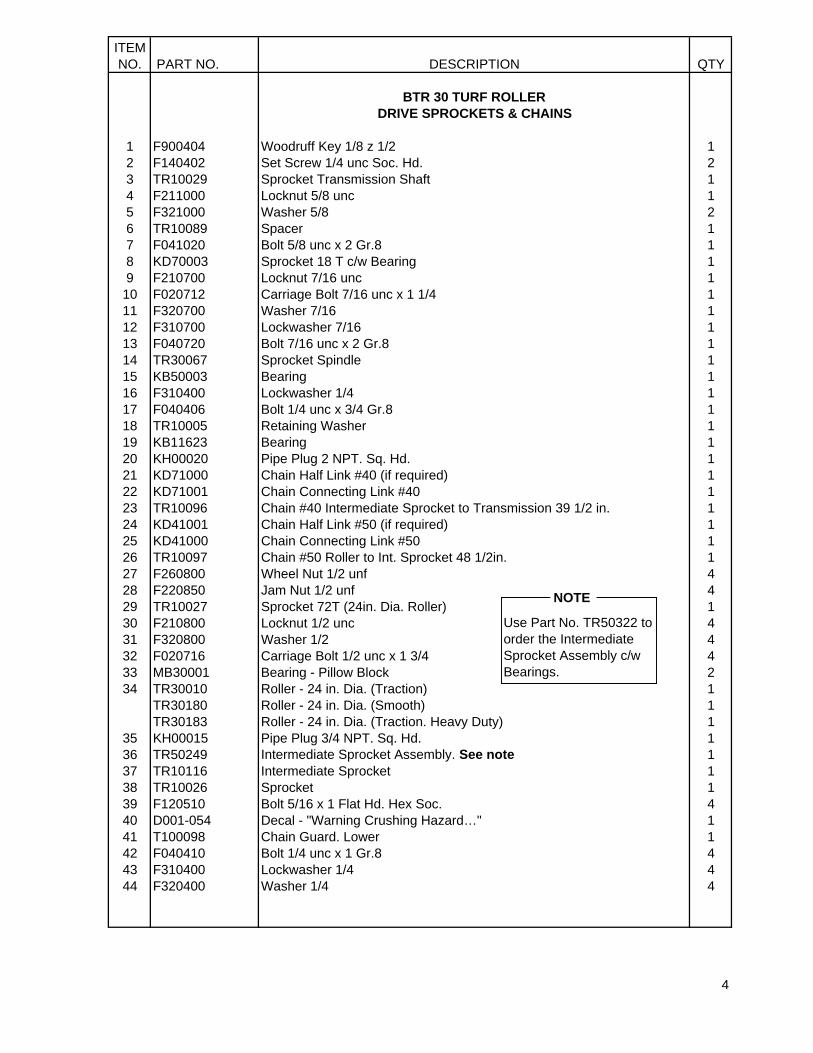
ITEMNO. PART NO. DESCRIPTION QTY
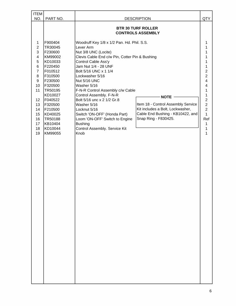
BTR 30 TURF ROLLER CONTROLS ASSEMBLY
1 F900404 Woodruff Key 1/8 x 1/2 Pan. Hd. Phil. S.S. 12 TR30045 Lever Arm 13 F230600 Nut 3/8 UNC (Locite) 14 KM99002 Clevis Cable End c/w Pin, Cotter Pin & Bushing 15 KD10033 Control Cable Ass'y 16 F220450 Jam Nut 1/4 - 28 UNF 17 F010512 Bolt 5/16 UNC x 1 1/4 28 F310500 Lockwasher 5/16 29 F230500 Nut 5/16 UNC 410 F320500 Washer 5/16 411 TR50195 F-N-R Control Assembly c/w Cable 1 KD10027 Control Assembly. F-N-R 1
12 F040522 Bolt 5/16 unc x 2 1/2 Gr.8 213 F320500 Washer 5/16 214 F210500 Locknut 5/16 215 KD40025 Switch 'ON-OFF' (Honda Part) 116 TR50188 Loom 'ON-OFF' Switch to Engine Ref17 KB10404 Bushing 118 KD10044 Control Assembly. Service Kit 119 KM99055 Knob 1
6
NOTEItem 18 - Control Assembly Service Kit includes a Bolt, Lockwasher, Cable End Bushing - KB10422, and Snap Ring - F830425.
NOTE
41
CURRENT
42
44
43
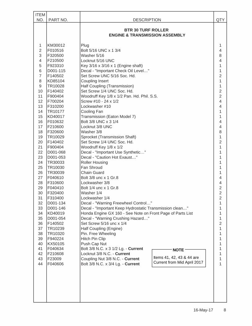
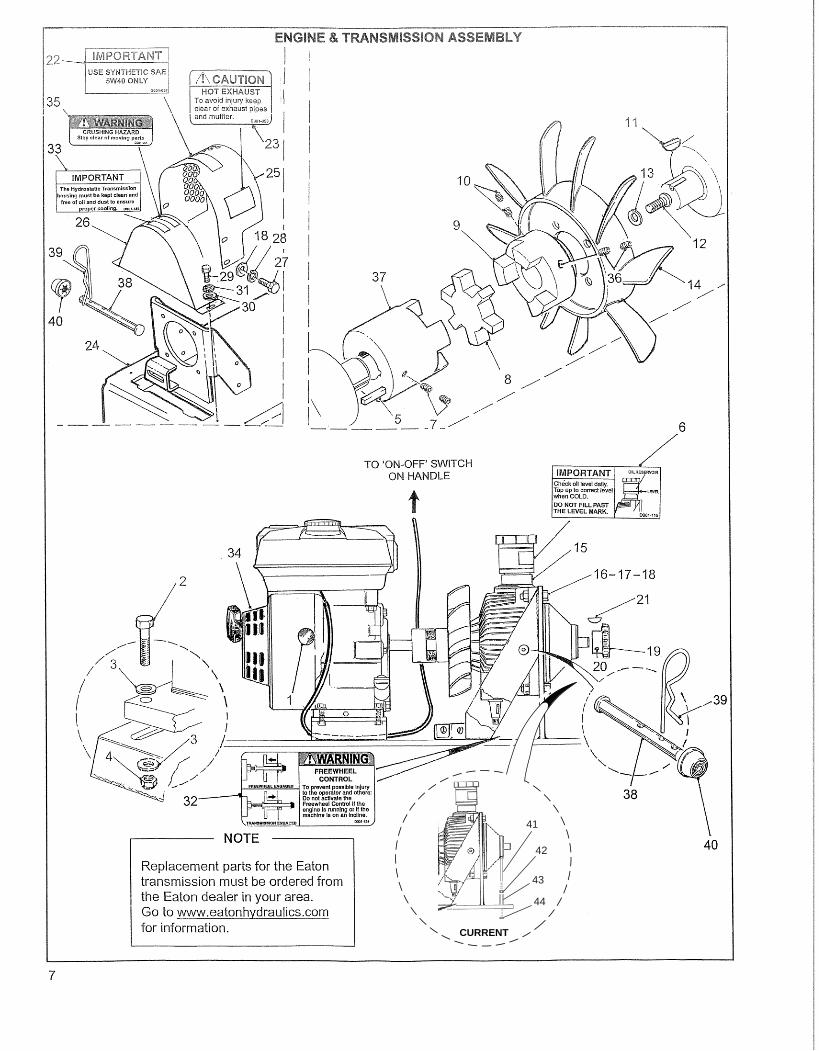
ITEMNO. PART NO. DESCRIPTION QTY
BTR 30 TURF ROLLER ENGINE & TRANSMISSION ASSEMBLY
1 KM30012 Plug 12 F010516 Bolt 5/16 UNC x 1 3/4 43 F320500 Washer 5/16 84 F210500 Locknut 5/16 UNC 45 F923310 Key 3/16 x 3/16 x 1 (Engine shaft) 16 D001-115 Decal - "Important Check Oil Level…" 17 F140502 Set Screw UNC 5/16 Soc. Hd. 28 KD85104 Coupling Insert 19 TR10028 Half Coupling (Transmission) 110 F140402 Set Screw 1/4 UNC Soc. Hd. 211 F900404 Woodruff Key 1/8 x 1/2 Pan. Hd. Phil. S.S. 212 F700204 Screw #10 - 24 x 1/2 413 F310200 Lockwasher #10 414 TR10177 Cooling Fan 115 KD40017 Transmission (Eaton Model 7) 116 F010632 Bolt 3/8 UNC x 3 1/4 417 F210600 Locknut 3/8 UNC 418 F320600 Washer 3/8 819 TR10029 Sprocket (Transmission Shaft) 120 F140402 Set Screw 1/4 UNC Soc. Hd. 221 F900404 Woodruff Key 1/8 x 1/2 122 D001-068 Decal - "Important Use Synthetic…" 123 D001-053 Decal - "Caution Hot Exaust…" 124 TR30033 Roller Housing 125 TR10030 Fan Shroud 126 TR30039 Chain Guard 127 F040610 Bolt 3/8 unc x 1 Gr.8 428 F310600 Lockwasher 3/8 429 F040410 Bolt 1/4 unc x 1 Gr.8 230 F320400 Washer 1/4 231 F310400 Lockwasher 1/4 232 D001-134 Decal - "Warning Freewheel Control…" 133 D001-146 Decal - "Important Keep Hydrostatic Transmission clean…" 134 KD40019 Honda Engine GX 160 - See Note on Front Page of Parts List 135 D001-054 Decal - "Warning Crushing Hazard…" 136 F140502 Set Screw 5/16 unc x 1/4 237 TR10239 Half Coupling (Engine) 138 TR10320 Pin. Free Wheeling 139 F940224 Hitch Pin Clip 140 KX50105 Push Cap Nut 1
8
41 F040634 Bolt 3/8 N.C. x 3 1/2 Lg. - Current 142 F210608 Locknut 3/8 N.C. - Current 143 F23009 Coupling Nut 3/8 N.C. - Current 144 F040606 Bolt 3/8 N.C. x 3/4 Lg. - Current 1
Items 41, 42, 43 & 44 areCurrent from Mid April 2017
NOTE
16-May-17
ITEMNO. PART NO. DESCRIPTION QTY
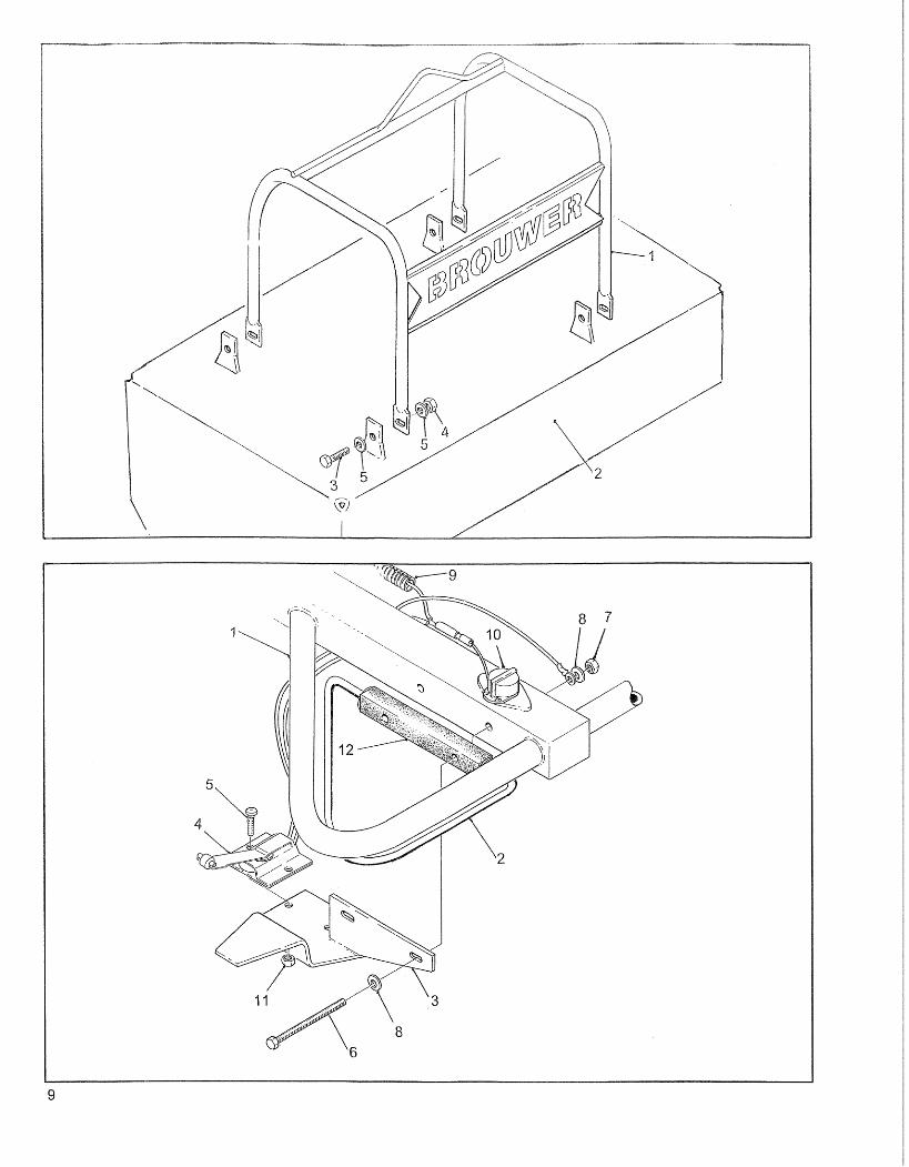
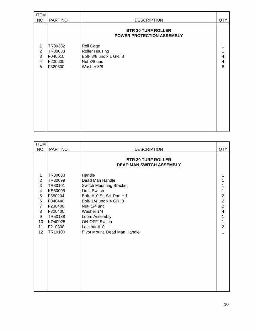
BTR 30 TURF ROLLER POWER PROTECTION ASSEMBLY
1 TR30382 Roll Cage 12 TR30033 Roller Housing 13 F040610 Bolt- 3/8 unc x 1 GR. 8 44 F230600 Nut 3/8 unc 45 F320600 Washer 3/8 8
ITEMNO. PART NO. DESCRIPTION QTY
BTR 30 TURF ROLLER DEAD MAN SWITCH ASSEMBLY
1 TR30083 Handle 12 TR30099 Dead Man Handle 13 TR30101 Switch Mounting Bracket 14 KE80005 Limit Switch 15 F580204 Bolt- #10 St. Stl. Pan Hd. 26 F040440 Bolt- 1/4 unc x 4 GR. 8 27 F230400 Nut- 1/4 unc 28 F320400 Washer 1/4 49 TR50188 Loom Assembly 110 KD40025 ON-OFF' Switch 111 F210300 Locknut #10 212 TR10100 Pivot Mount. Dead Man Handle 1
10

This page intentionally blank.
11
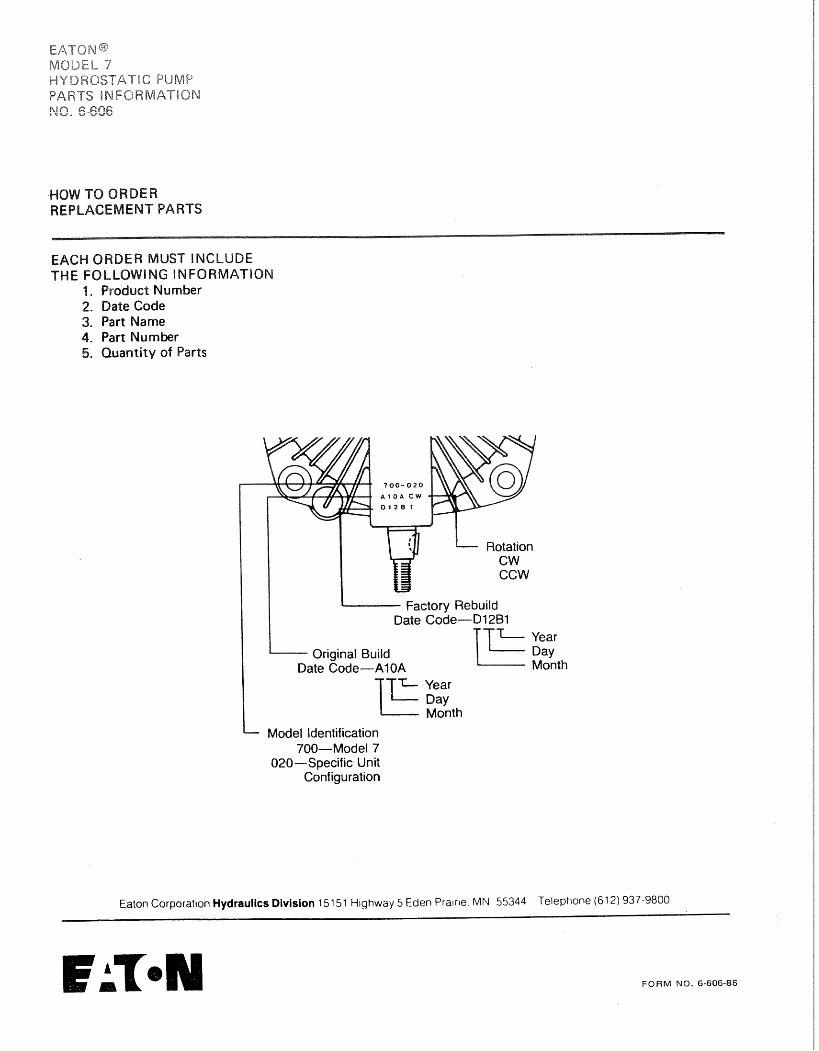
ITEMNO. PART NO. DESCRIPTION QTY
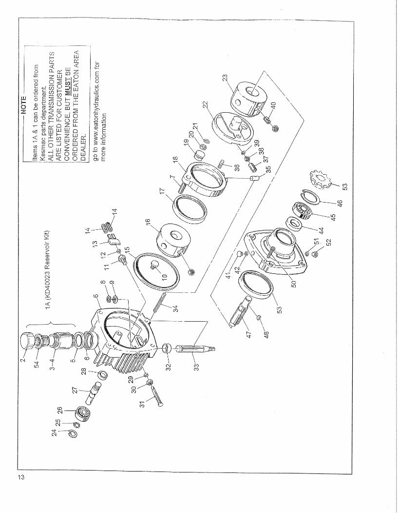
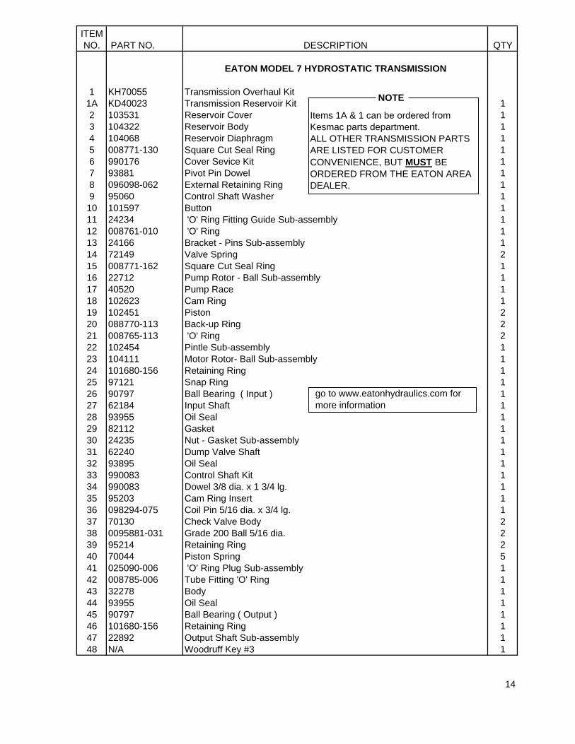
EATON MODEL 7 HYDROSTATIC TRANSMISSION
1 KH70055 Transmission Overhaul Kit 1A KD40023 Transmission Reservoir Kit 12 103531 Reservoir Cover 13 104322 Reservoir Body 14 104068 Reservoir Diaphragm 15 008771-130 Square Cut Seal Ring 16 990176 Cover Sevice Kit 17 93881 Pivot Pin Dowel 18 096098-062 External Retaining Ring 19 95060 Control Shaft Washer 110 101597 Button 111 24234 'O' Ring Fitting Guide Sub-assembly 112 008761-010 'O' Ring 113 24166 Bracket - Pins Sub-assembly 114 72149 Valve Spring 215 008771-162 Square Cut Seal Ring 116 22712 Pump Rotor - Ball Sub-assembly 117 40520 Pump Race 118 102623 Cam Ring 119 102451 Piston 220 088770-113 Back-up Ring 221 008765-113 'O' Ring 222 102454 Pintle Sub-assembly 123 104111 Motor Rotor- Ball Sub-assembly 124 101680-156 Retaining Ring 125 97121 Snap Ring 126 90797 Ball Bearing ( Input ) 127 62184 Input Shaft 128 93955 Oil Seal 129 82112 Gasket 130 24235 Nut - Gasket Sub-assembly 131 62240 Dump Valve Shaft 132 93895 Oil Seal 133 990083 Control Shaft Kit 134 990083 Dowel 3/8 dia. x 1 3/4 lg. 135 95203 Cam Ring Insert 136 098294-075 Coil Pin 5/16 dia. x 3/4 lg. 137 70130 Check Valve Body 238 0095881-031 Grade 200 Ball 5/16 dia. 239 95214 Retaining Ring 240 70044 Piston Spring 541 025090-006 'O' Ring Plug Sub-assembly 142 008785-006 Tube Fitting 'O' Ring 143 32278 Body 144 93955 Oil Seal 145 90797 Ball Bearing ( Output ) 146 101680-156 Retaining Ring 147 22892 Output Shaft Sub-assembly 148 N/A Woodruff Key #3 1
14
Items 1A & 1 can be ordered from Kesmac parts department.ALL OTHER TRANSMISSION PARTS ARE LISTED FOR CUSTOMER CONVENIENCE, BUT MUST BE ORDERED FROM THE EATON AREA DEALER.
go to www.eatonhydraulics.com for more information
NOTE
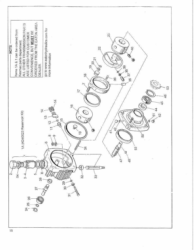

ITEMNO. PART NO. DESCRIPTION QTY
EATON MODEL 7 HYDROSTATIC TRANSMISSION
49 40519 Motor Race 150 095912-125 Socket Hd. Capscrew 251 008785-006 Tube Fitting 'O' Ring 152 025090-005 'O' Ring Plug Assembly 153 TR10029 Sprocket (Transmission Shaft) ref54 KD40033 Diaphragm. Reservoir 1
16