BTL6-U110-M -PF-S4 User's Guide - Balluffusa.balluff.com/OTPDF/BTLManuals/891248_BTL6-U110... ·...
22
BTL6-U110-M_ _ _ _-PF-S4 User's Guide English
Transcript of BTL6-U110-M -PF-S4 User's Guide - Balluffusa.balluff.com/OTPDF/BTLManuals/891248_BTL6-U110... ·...
BTL6-U110-M _ _ _ _ -PF-S4
User's Guide
English

www.balluff.com
www.balluff.com 3english
BTL6-U110-M _ _ _ _ -PF-S4Micropulse Transducer in a Flat Profile Housing
1 Notes to the user 5
1.1 Validity 51.2 Symbols and conventions 51.3 Scope of delivery 51.4 Approvals and markings 5
2 Safety 6
2.1 Intended use 62.2 General safety notes for the position measuring system 62.3 Explanation of the warnings 62.4 Disposal 6
3 Construction and function 7
3.1 Construction 73.2 Function 73.3 LED display 7
4 Installation and connection 8
4.1 Installing the transducer 84.2 Captive magnets 84.3 Floating magnets 94.4 Electrical connection 104.5 Cable routing 10
5 Startup 11
5.1 Starting up the system 115.2 Operating notes 11
6 IO-Link interface 12
6.1 Basic knowledge about IO-Link 126.2 Device specification 136.3 Process data 136.4 Parameter data 146.5 Diagnostic data 15
7 Technical data 16
7.1 Accuracy 167.2 Ambient conditions 167.3 Supply voltage (external) 167.4 IO-Link interface 167.5 Dimensions, weights 16
8 Accessories 17
8.1 Floating magnets 178.2 Captive magnets 188.3 BTL2-GS10-_ _ _ _-A joint rod 188.4 Connector 19

4 english
BTL6-U110-M _ _ _ _ -PF-S4Micropulse Transducer in a Flat Profile Housing
9 Type code breakdown 20
10 Appendix 21
10.1 Converting units of length 2110.2 Part label 21
www.balluff.com 5english
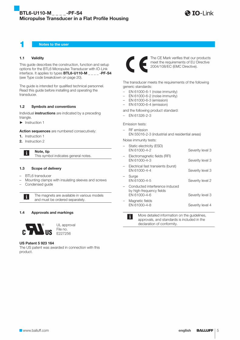
1.1 Validity
This guide describes the construction, function and setup options for the BTL6 Micropulse Transducer with IO-Link interface. It applies to types BTL6-U110-M _ _ _ _ -PF-S4 (see Type code breakdown on page 20).
The guide is intended for qualified technical personnel. Read this guide before installing and operating the transducer.
1.2 Symbols and conventions
Individual instructions are indicated by a preceding triangle.
► Instruction 1
Action sequences are numbered consecutively:1. Instruction 12. Instruction 2
Note, tipThis symbol indicates general notes.
1.3 Scope of delivery
– BTL6 transducer– Mounting clamps with insulating sleeves and screws– Condensed guide
The magnets are available in various models and must be ordered separately.
1.4 Approvals and markings
UL approvalFile no.E227256
US Patent 5 923 164The US patent was awarded in connection with this product.
The CE Mark verifies that our products meet the requirements of EU Directive 2004/108/EC (EMC Directive).
The transducer meets the requirements of the following generic standards:– EN 61000-6-1 (noise immunity)– EN 61000-6-2 (noise immunity)– EN 61000-6-3 (emission)– EN 61000-6-4 (emission)
and the following product standard:– EN 61326-2-3
Emission tests:
– RF emission EN 55016-2-3 (industrial and residential areas)
Noise immunity tests:
– Static electricity (ESD) EN 61000-4-2 Severity level 3
– Electromagnetic fields (RFI) EN 61000-4-3 Severity level 3
– Electrical fast transients (burst) EN 61000-4-4 Severity level 3
– Surge EN 61000-4-5 Severity level 2
– Conducted interference induced by high-frequency fields EN 61000-4-6 Severity level 3
– Magnetic fields EN 61000-4-8 Severity level 4
More detailed information on the guidelines, approvals, and standards is included in the declaration of conformity.
1 Notes to the user
BTL6-U110-M _ _ _ _ -PF-S4Micropulse Transducer in a Flat Profile Housing
6 english
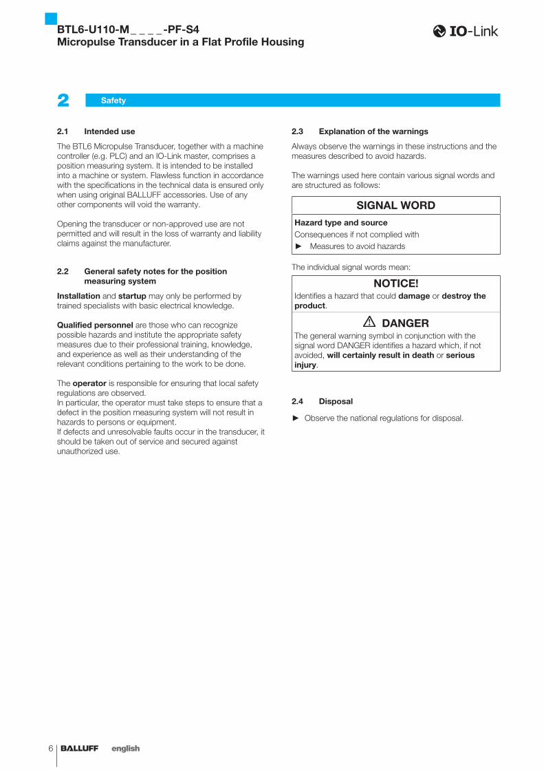
2.1 Intended use
The BTL6 Micropulse Transducer, together with a machine controller (e.g. PLC) and an IO-Link master, comprises a position measuring system. It is intended to be installed into a machine or system. Flawless function in accordance with the specifications in the technical data is ensured only when using original BALLUFF accessories. Use of any other components will void the warranty.
Opening the transducer or non-approved use are not permitted and will result in the loss of warranty and liability claims against the manufacturer.
2.2 General safety notes for the position measuring system
Installation and startup may only be performed by trained specialists with basic electrical knowledge.
Qualified personnel are those who can recognize possible hazards and institute the appropriate safety measures due to their professional training, knowledge, and experience as well as their understanding of the relevant conditions pertaining to the work to be done.
The operator is responsible for ensuring that local safety regulations are observed.In particular, the operator must take steps to ensure that a defect in the position measuring system will not result in hazards to persons or equipment.If defects and unresolvable faults occur in the transducer, it should be taken out of service and secured against unauthorized use.
2.3 Explanation of the warnings
Always observe the warnings in these instructions and the measures described to avoid hazards.
The warnings used here contain various signal words and are structured as follows:
SIGNAL WORDHazard type and sourceConsequences if not complied with
► Measures to avoid hazards
The individual signal words mean:
NOTICE!Identifies a hazard that could damage or destroy the product.
DANGERThe general warning symbol in conjunction with the signal word DANGER identifies a hazard which, if not avoided, will certainly result in death or serious injury.
2.4 Disposal
► Observe the national regulations for disposal.
2 Safety
BTL6-U110-M _ _ _ _ -PF-S4Micropulse Transducer in a Flat Profile Housing
www.balluff.com 7english
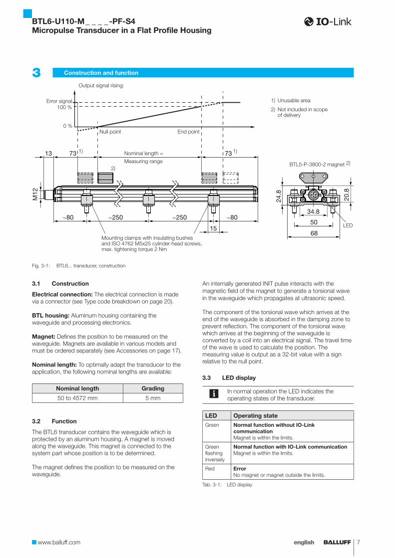
3.1 Construction
Electrical connection: The electrical connection is made via a connector (see Type code breakdown on page 20).
BTL housing: Aluminum housing containing the waveguide and processing electronics.
Magnet: Defines the position to be measured on the waveguide. Magnets are available in various models and must be ordered separately (see Accessories on page 17).
Nominal length: To optimally adapt the transducer to the application, the following nominal lengths are available:
Nominal length Grading
50 to 4572 mm 5 mm
3.2 Function
The BTL6 transducer contains the waveguide which is protected by an aluminum housing. A magnet is moved along the waveguide. This magnet is connected to the system part whose position is to be determined.
The magnet defines the position to be measured on the waveguide.
An internally generated INIT pulse interacts with the magnetic field of the magnet to generate a torsional wave in the waveguide which propagates at ultrasonic speed.
The component of the torsional wave which arrives at the end of the waveguide is absorbed in the damping zone to prevent reflection. The component of the torsional wave which arrives at the beginning of the waveguide is converted by a coil into an electrical signal. The travel time of the wave is used to calculate the position. The measuring value is output as a 32-bit value with a sign relative to the null point.
3.3 LED display
In normal operation the LED indicates the operating states of the transducer.
LED Operating state
Green Normal function without IO-Link communicationMagnet is within the limits.
Green flashing inversely
Normal function with IO-Link communicationMagnet is within the limits.
Red ErrorNo magnet or magnet outside the limits.
Tab. 3-1: LED display
Fig. 3-1: BTL6... transducer, construction
3 Construction and function
2)
13 73 73
~80 ~80~250 ~250
1550
34.8
68
24.8
20.8
M12
1) Unusable area
2) Not included in scope of delivery
1) Nominal length =
Measuring range
Null point End point
Output signal rising:
Error signal100 %
0 %
BTL5-P-3800-2 magnet
1)
Mounting clamps with insulating bushesand ISO 4762 M5x25 cylinder-head screws,max. tightening torque 2 Nm
2)
LED
BTL6-U110-M _ _ _ _ -PF-S4Micropulse Transducer in a Flat Profile Housing
8 english
4.1 Installing the transducer
NOTICE!Improper installationImproper installation can compromise the function of the transducer and result in damage.
► For this reason, ensure that no strong electrical or magnetic fields are present in the immediate vicinity of the transducer.
► The recommended spacing for the installation must be strictly observed.
Any orientation is permitted. Mount the transducer on a level surface of the machine using the provided mounting clamps and cylinder-head screws. A sufficient number of mounting clamps is supplied.
In order to avoid the development of resonant frequencies from vibration loads, we recommend arranging the mounting clamps at irregular intervals.
The transducer is electrically isolated from the machine with the supplied insulating bushes (see Figure 3-1).
1. Guide the transducer into the mounting clamps.2. Attach transducer to the base using mounting screws
(tighten screws in the clamps with max. 2 Nm).3. Insert magnet (accessories).
The micropulse transducer in profile housing is suitable both for floating, i.e. non-contacting magnets (see Figures 4-3 to 4-7) and for captive magnets (see Figures 4-1 and 4-2).
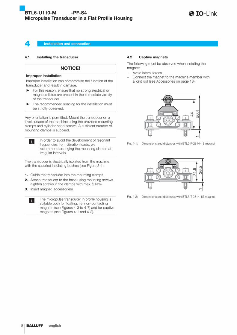
4.2 Captive magnets
The following must be observed when installing the magnet:– Avoid lateral forces.– Connect the magnet to the machine member with
a joint rod (see Accessories on page 18).
Fig. 4-1:
150
.444
Dimensions and distances with BTL5-F-2814-1S magnet
Fig. 4-2: 1
36.5
31.5
Dimensions and distances with BTL5-T-2814-1S magnet
4 Installation and connection
BTL6-U110-M _ _ _ _ -PF-S4Micropulse Transducer in a Flat Profile Housing
www.balluff.com 9english
4 Installation and connection (continued)
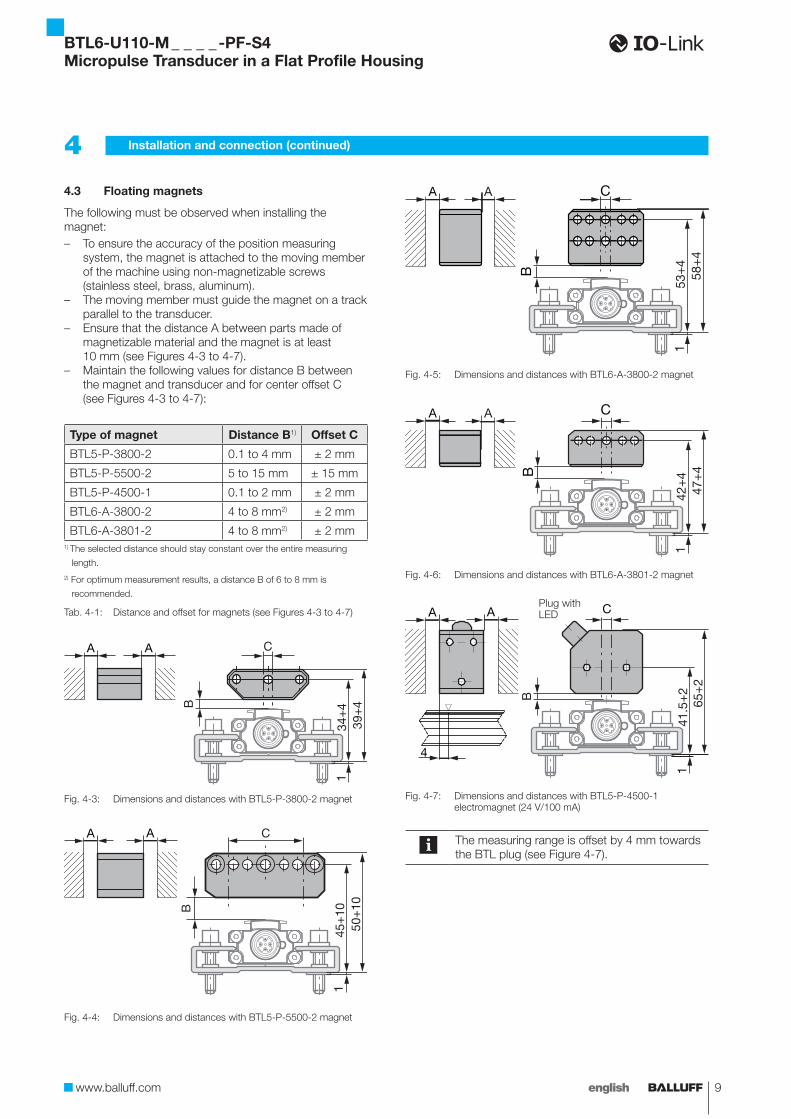
4.3 Floating magnets
The following must be observed when installing the magnet:– To ensure the accuracy of the position measuring
system, the magnet is attached to the moving member of the machine using non-magnetizable screws (stainless steel, brass, aluminum).
– The moving member must guide the magnet on a track parallel to the transducer.
– Ensure that the distance A between parts made of magnetizable material and the magnet is at least 10 mm (see Figures 4-3 to 4-7).
– Maintain the following values for distance B between the magnet and transducer and for center offset C (see Figures 4-3 to 4-7):
Type of magnet Distance B1) Offset C
BTL5-P-3800-2 0.1 to 4 mm ± 2 mm
BTL5-P-5500-2 5 to 15 mm ± 15 mm
BTL5-P-4500-1 0.1 to 2 mm ± 2 mm
BTL6-A-3800-2 4 to 8 mm2) ± 2 mm
BTL6-A-3801-2 4 to 8 mm2) ± 2 mm1) The selected distance should stay constant over the entire measuring
length.2) For optimum measurement results, a distance B of 6 to 8 mm is
recommended.
Tab. 4-1: Distance and offset for magnets (see Figures 4-3 to 4-7)
Fig. 4-3:
B
C
134
+4
AA
39+
4
Dimensions and distances with BTL5-P-3800-2 magnet
Fig. 4-4:
C
B
1
AA
45+
1050
+10
Dimensions and distances with BTL5-P-5500-2 magnet
Fig. 4-5:
C
B
1
AA
58+
453
+4
Dimensions and distances with BTL6-A-3800-2 magnet
Fig. 4-6:
C
B
1
AA
47+
442
+4
Dimensions and distances with BTL6-A-3801-2 magnet
Fig. 4-7:
165
+2
B
AA C
41.5
+2
4
Dimensions and distances with BTL5-P-4500-1 electromagnet (24 V/100 mA)
The measuring range is offset by 4 mm towards the BTL plug (see Figure 4-7).
Plug with LED
BTL6-U110-M _ _ _ _ -PF-S4Micropulse Transducer in a Flat Profile Housing
10 english
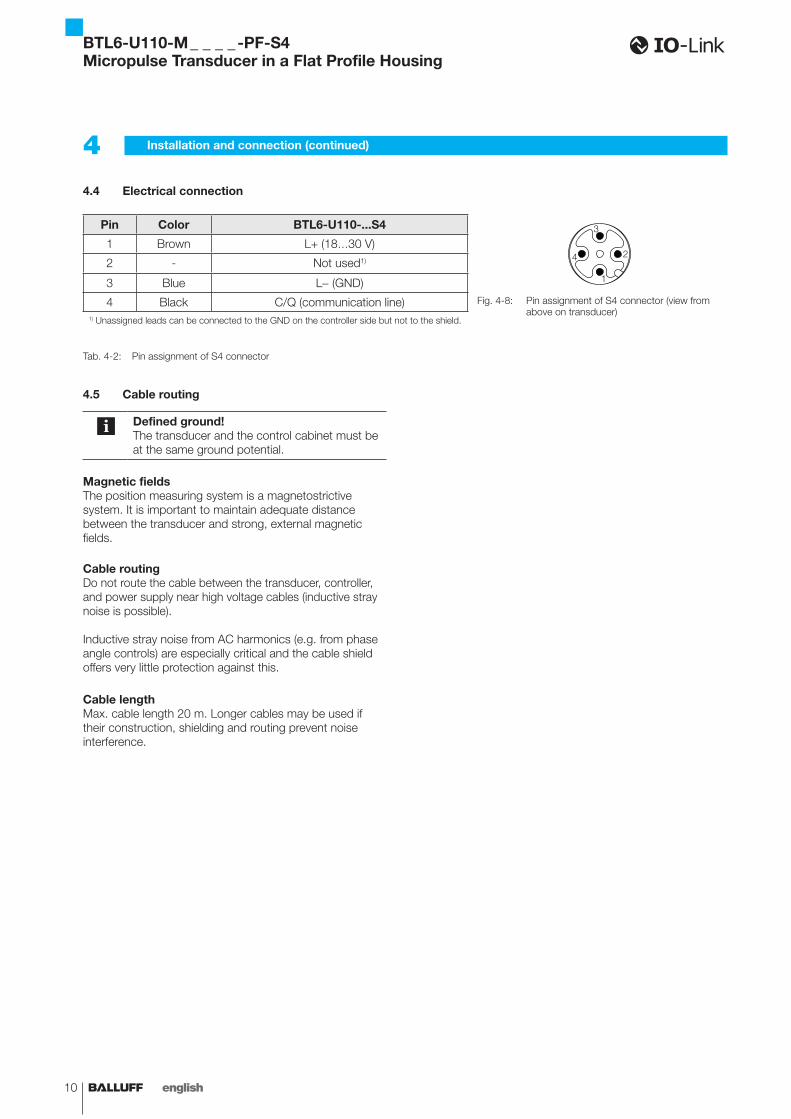
4.4 Electrical connection
Pin Color BTL6-U110-...S4
1
2
3
4
Fig. 4-8: Pin assignment of S4 connector (view from above on transducer)
1 Brown L+ (18…30 V)
2 - Not used1)
3 Blue L- (GND)
4 Black C/Q (communication line)1) Unassigned leads can be connected to the GND on the controller side but not to the shield.
Tab. 4-2: Pin assignment of S4 connector
4.5 Cable routing
Defined ground!The transducer and the control cabinet must be at the same ground potential.
Magnetic fieldsThe position measuring system is a magnetostrictive system. It is important to maintain adequate distance between the transducer and strong, external magnetic fields.
Cable routingDo not route the cable between the transducer, controller, and power supply near high voltage cables (inductive stray noise is possible).
Inductive stray noise from AC harmonics (e.g. from phase angle controls) are especially critical and the cable shield offers very little protection against this.
Cable lengthMax. cable length 20 m. Longer cables may be used if their construction, shielding and routing prevent noise interference.
4 Installation and connection (continued)
BTL6-U110-M _ _ _ _ -PF-S4Micropulse Transducer in a Flat Profile Housing

www.balluff.com 11english
5.1 Starting up the system
DANGERUncontrolled system movementWhen starting up, if the position measuring system is part of a closed loop system whose parameters have not yet been set, the system may perform uncontrolled movements. This could result in personal injury and equipment damage.
► Persons must keep away from the system's hazardous zones.
► Startup must be performed only by trained technical personnel.
► Observe the safety instructions of the equipment or system manufacturer.
1. Check connections for tightness and correct polarity. Replace damaged connections.
2. Turn on the system.3. Check measured values and adjustable parameters
and readjust the transducer, if necessary.
Check for the correct values at the null point and end point, especially after replacing the transducer or after repair by the manufacturer.
5.2 Operating notes
– Check the function of the transducer and all associated components on a regular basis.
– Take the position measuring system out of operation whenever there is a malfunction.
– Secure the system against unauthorized use.
5 Startup
BTL6-U110-M _ _ _ _ -PF-S4Micropulse Transducer in a Flat Profile Housing
12 english
6.1 Basic knowledge about IO-Link
GeneralIO-Link integrates conventional and intelligent sensors and actuators in automation systems and is intended as a communication standard within classic field buses. Field-bus-independent transfer uses communication systems that are already available (field buses or Ethernet-based systems).
IO-Link devices, such as sensors and actuators, are connected to the controlling system using a point-to-point connection via a gateway, the IO-Link master. The IO-Link devices are connected using commercially available unshielded standard sensor cables.
Communication is based on a standard UART protocol with a 24-V pulse modulation in half-duplex operation. This allows classic three-conductor physics.
ProtocolWith IO-Link communication, permanently defined frames are cyclically exchanged between the IO-Link master and the IO-Link device. In this protocol, both process and required data, such as parameters or diagnostic data, is transferred. The size and the type of the frame and cycle time used result from the combination of master and device features (see device specification on page 13).
Cycle timeThe cycle time used (master cycle time) results from the minimum possible cycle time of the IO-Link device (min cycle time) and the minimum possible cycle time of the IO-Link master. When selecting the IO-Link master, please note that the larger value determines the cycle time used.
Protocol version 1.0 / 1.1In protocol version 1.0, process data larger than 2 bytes was transferred spread over multiple cycles.
From protocol version 1.1, all available process data is transferred in one frame. Thus, the cycle time (master cycle time) is identical to the process data cycle.
The BTL6-U110-… transducer is optimized for protocol version 1.1 and cycle time. Operating the IO-Link device on an IO-Link master with protocol version 1.0 results in longer transfer times (process data cycle ~ amount of process data x master cycle time).
Parameter managementA parameter manager that enables device parameters to be saved on the IO-Link master is defined in protocol version 1.1. When exchanging an IO-Link device, the parameter data of the previous IO-Link device can be taken over. The operation of this parameter manager is dependent on the IO-Link master and is explained in the corresponding description.
All parameters saved in the IO-Link master for parameter management are indicated correspondingly in table 6-3 (see parameter data on page 14).
Device functions and master gatewayThe BTL6-U110-… transducer functions are described in detail in chapters 6.3 to 6.5. How process, parameter and diagnostic data is implemented via the master gateway can be found in the instructions for the IO-Link master.
6 IO-Link interface
BTL6-U110-M _ _ _ _ -PF-S4Micropulse Transducer in a Flat Profile Housing
www.balluff.com 13english
6 IO-Link interface (continued)
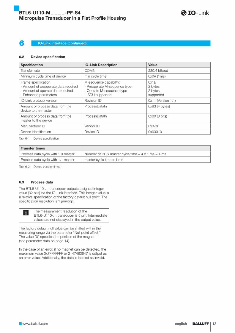
6.2 Device specification
Specification IO-Link Description Value
Transfer rate COM3 230.4 kBaud
Minimum cycle time of device min cycle time 0x0A (1ms)
Frame specification- Amount of preoperate data required- Amount of operate data required- Enhanced parameters
M-sequence capability:- Preoperate M-sequence type- Operate M-sequence type- ISDU supported
0x1B2 bytes2 bytessupported
IO-Link protocol version Revision ID 0x11 (Version 1.1)
Amount of process data from the device to the master
ProcessDataIn 0x83 (4 bytes)
Amount of process data from the master to the device
ProcessDataIn 0x00 (0 bits)
Manufacturer ID Vendor ID 0x378
Device identification Device ID 0x030101
Tab. 6-1: Device specification
Transfer times
Process data cycle with 1.0 master Number of PD x master cycle time = 4 x 1 ms = 4 ms
Process data cycle with 1.1 master master cycle time = 1 ms
Tab. 6-2: Device transfer times
6.3 Process data
The BTL6-U110-… transducer outputs a signed integer value (32 bits) via the IO-Link interface. This integer value is a relative specification of the factory default null point. The specification resolution is 1 µm/digit.
The measurement resolution of the BTL6-U110-… transducer is 5 µm. Intermediate values are not displayed in the output value.
The factory default null value can be shifted within the measuring range via the parameter "Null point offset." The value "0" specifies the position of the magnet (see parameter data on page 14).
In the case of an error, if no magnet can be detected, the maximum value 0x7FFFFFFF or 2147483647 is output as an error value. Additionally, the data is labeled as invalid.
BTL6-U110-M _ _ _ _ -PF-S4Micropulse Transducer in a Flat Profile Housing
14 english
6 IO-Link interface (continued)
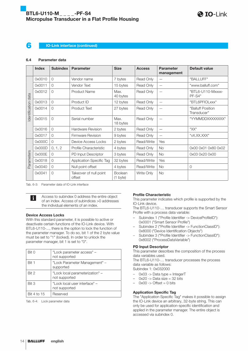
6.4 Parameter data
Index Subindex Parameter Size Access Parameter management
Default value
Iden
tific
atio
n da
ta
0x0010 0 Vendor name 7 bytes Read Only — "BALLUFF"
0x0011 0 Vendor Text 15 bytes Read Only — "www.balluff.com"
0x0012 0 Product Name Max. 40 bytes
Read Only — "BTL6-U110-Mxxxx-PF-S4"
0x0013 0 Product ID 12 bytes Read Only — "BTL6PFIOLxxx"
0x0014 0 Product Text 27 bytes Read Only — "Balluff Position Transducer"
0x0015 0 Serial number Max. 18 bytes
Read Only — "YYMMDDXXXXXXXX"
0x0016 0 Hardware Revision 2 bytes Read Only — "XX"
0x0017 0 Firmware Revision 9 bytes Read Only — "vX.XX.XXX"
Par
amet
ers
0x000C 0 Device Access Locks 2 bytes Read/Write Yes
0x000D 0, 1, 2 Profile Characteristic 4 bytes Read Only No 0x00 0x01 0x80 0x02
0x000E 0 PD Input Descriptor 3 bytes Read Only No 0x03 0x20 0x00
0x0018 0 Application Specific Tag 32 bytes Read/Write Yes
0x0040 0 Null point offset 4 bytes Read/Write No 0
0x0041 0 Takeover of null point offset
Boolean (1 byte)
Write Only No
Tab. 6-3: Parameter data of IO-Link interface
Access to subindex 0 address the entire object of an index. Access of subindices >0 addresses the individual elements of an index.
Device Access LocksWith this standard parameter, it is possible to active or deactivate certain functions of the IO-Link device. With BTL6-U110-..., there is the option to lock the function of the parameter manager. To do so, bit 1 of the 2 byte value must be set to "1" (locked). In order to unlock the parameter manager, bit 1 is set to "0".
Bit 0 "Lock parameter access" – not supported
Bit 1 "Lock Parameter Management" – supported
Bit 2 "Lock local parameterization" – not supported
Bit 3 "Lock local user interface" – not supported
Bit 4 to 15 Reserved
Tab. 6-4: Lock parameter data
Profile CharacteristicThis parameter indicates which profile is supported by the IO-Link device. The BTL6-U110-… transducer supports the Smart Sensor Profile with a process data variable:– Subindex 1 ("Profile Identifier -> DeviceProfileID"):
0x0001 ("Smart Sensor Profile")– Subindex 2 ("Profile Identifier -> FunctionClassID"):
0x8000 ("Device Identification Objects")– Subindex 3 ("Profile Identifier -> FunctionClassID"):
0x8002 ("ProcessDataVariable")
PD Input DescriptorThis parameter describes the composition of the process data variables used.The BTL6-U110-… transducer processes the process data variable as follows:Subindex 1: 0x032000– 0x03 -> Data type = IntegerT– 0x20 -> Data size = 32 bits– 0x00 -> Offset = 0 bits
Application Specific TagThe "Application Specific Tag" makes it possible to assign the IO-Link device an arbitrary, 32-byte string. This can only be used for application-specific identification and applied in the parameter manager. The entire object is accessed via subindex 0.
BTL6-U110-M _ _ _ _ -PF-S4Micropulse Transducer in a Flat Profile Housing
www.balluff.com 15english
6 IO-Link interface (continued)
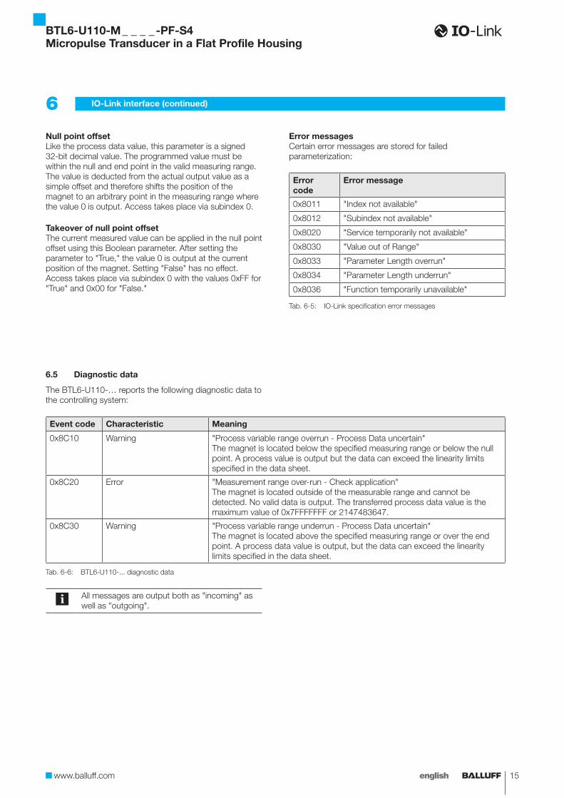
Null point offsetLike the process data value, this parameter is a signed 32-bit decimal value. The programmed value must be within the null and end point in the valid measuring range. The value is deducted from the actual output value as a simple offset and therefore shifts the position of the magnet to an arbitrary point in the measuring range where the value 0 is output. Access takes place via subindex 0.
Takeover of null point offsetThe current measured value can be applied in the null point offset using this Boolean parameter. After setting the parameter to "True," the value 0 is output at the current position of the magnet. Setting "False" has no effect. Access takes place via subindex 0 with the values 0xFF for "True" and 0x00 for "False."
Error messagesCertain error messages are stored for failed parameterization:
Error code
Error message
0x8011 "Index not available"
0x8012 "Subindex not available"
0x8020 "Service temporarily not available"
0x8030 "Value out of Range"
0x8033 "Parameter Length overrun"
0x8034 "Parameter Length underrun"
0x8036 "Function temporarily unavailable"
Tab. 6-5: IO-Link specification error messages
6.5 Diagnostic data
The BTL6-U110-… reports the following diagnostic data to the controlling system:
Event code Characteristic Meaning
0x8C10 Warning "Process variable range overrun - Process Data uncertain"The magnet is located below the specified measuring range or below the null point. A process value is output but the data can exceed the linearity limits specified in the data sheet.
0x8C20 Error "Measurement range over-run - Check application"The magnet is located outside of the measurable range and cannot be detected. No valid data is output. The transferred process data value is the maximum value of 0x7FFFFFFF or 2147483647.
0x8C30 Warning "Process variable range underrun - Process Data uncertain"The magnet is located above the specified measuring range or over the end point. A process data value is output, but the data can exceed the linearity limits specified in the data sheet.
Tab. 6-6: BTL6-U110-... diagnostic data
All messages are output both as "incoming" as well as "outgoing".
BTL6-U110-M _ _ _ _ -PF-S4Micropulse Transducer in a Flat Profile Housing
16 english
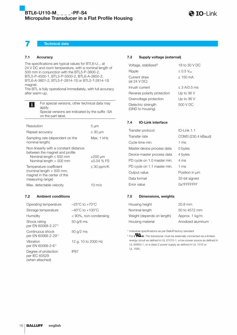
7.1 Accuracy
The specifications are typical values for BTL6-U... at 24 V DC and room temperature, with a nominal length of 500 mm in conjunction with the BTL5-P-3800-2, BTL5-P-4500-1, BTL5-P-5500-2, BTL6-A-3800-2, BTL6-A-3801-2, BTL5-F-2814-1S or BTL5-T-2814-1S magnet. The BTL is fully operational immediately, with full accuracy after warm-up.
For special versions, other technical data may apply.Special versions are indicated by the suffix -SA on the part label.
Resolution 5 µm
Repeat accuracy ≤ 30 µm
Sampling rate (dependent on the nominal length)
Max. 1 kHz
Non-linearity with a constant distance between the magnet and profile Nominal length ≤ 500 mm Nominal length > 500 mm
±200 µm±0.04 % FS
Temperature coefficient (nominal length = 500 mm, magnet in the center of the measuring range)
≤ 30 ppm/K
Max. detectable velocity 10 m/s
7.2 Ambient conditions
Operating temperature -25°C to +70°C
Storage temperature -40°C to +100°C
Humidity < 90%, non-condensing
Shock rating per EN 60068-2-271)
50 g/6 ms
Continuous shock per EN 60068-2-291)
50 g/2 ms
Vibration per EN 60068-2-61)
12 g, 10 to 2000 Hz
Degree of protection per IEC 60529
IP67
(when attached)
7.3 Supply voltage (external)
Voltage, stabilized2) 18 to 30 V DC
Ripple ≤ 0.5 VPP
Current draw (at 24 V DC)
≤ 150 mA
Inrush current ≤ 3 A/0.5 ms
Reverse polarity protection Up to 36 V
Overvoltage protection Up to 36 V
Dielectric strength (GND to housing)
500 V DC
7.4 IO-Link interface
Transfer protocol IO-Link 1.1
Transfer rate COM3 (230.4 kBaud)
Cycle time min. 1 ms
Master-device process data 0 bytes
Device-master process data 4 bytes
PD cycle on 1.0 master min. 4 ms
PD cycle on 1.1 master min. 1 ms
Output value Position in µm
Data format 32-bit signed
Error value 0x7FFFFFFF
7.5 Dimensions, weights
Housing height 20.8 mm
Nominal length 50 to 4572 mm
Weight (depends on length) Approx. 1 kg/m
Housing material Anodized aluminum
1) Individual specifications as per Balluff factory standard2) For : The transducer must be externally connected via a limited-
energy circuit as defined in UL 61010-1, a low-power source as defined in
UL 60950-1, or a class 2 power supply as defined in UL 1310 or
UL 1585.
7 Technical data
BTL6-U110-M _ _ _ _ -PF-S4Micropulse Transducer in a Flat Profile Housing
www.balluff.com 17english
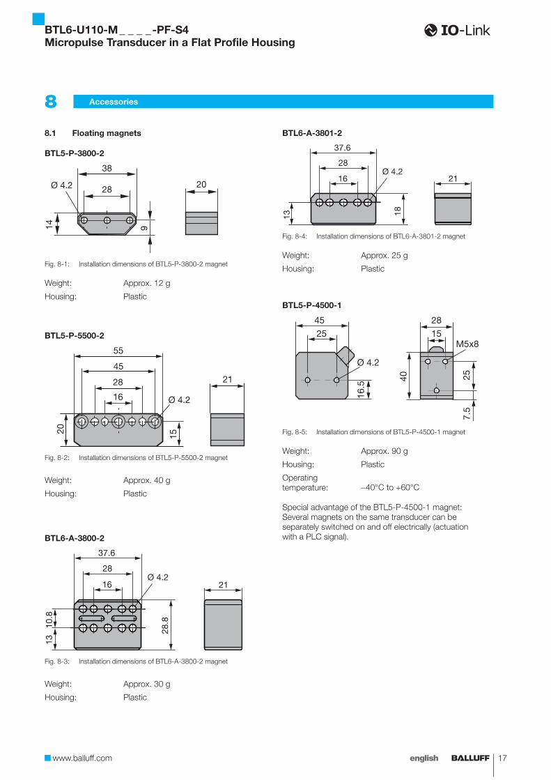
8.1 Floating magnets
BTL5-P-3800-2
38
28
914
Ø 4.2
Fig. 8-1: Installation dimensions of BTL5-P-3800-2 magnet
Weight: Approx. 12 g
Housing: Plastic
BTL5-P-5500-2
55
28
16
4521
Ø 4.2
20
15
Fig. 8-2: Installation dimensions of BTL5-P-5500-2 magnet
Weight: Approx. 40 g
Housing: Plastic
BTL6-A-3800-2
21
10.8
13
28.8
28
16
37.6
Ø 4.2
Fig. 8-3: Installation dimensions of BTL6-A-3800-2 magnet
Weight: Approx. 30 g
Housing: Plastic
BTL6-A-3801-2
28
16 21
37.6
Ø 4.2
1813
Fig. 8-4: Installation dimensions of BTL6-A-3801-2 magnet
Weight: Approx. 25 g
Housing: Plastic
BTL5-P-4500-1
16.5
45
25
28
15
Ø 4.2
257.
5
M5x8
40
Fig. 8-5: Installation dimensions of BTL5-P-4500-1 magnet
Weight: Approx. 90 g
Housing: Plastic
Operating temperature: -40°C to +60°C
Special advantage of the BTL5-P-4500-1 magnet: Several magnets on the same transducer can be separately switched on and off electrically (actuation with a PLC signal).
8 Accessories
BTL6-U110-M _ _ _ _ -PF-S4Micropulse Transducer in a Flat Profile Housing
18 english
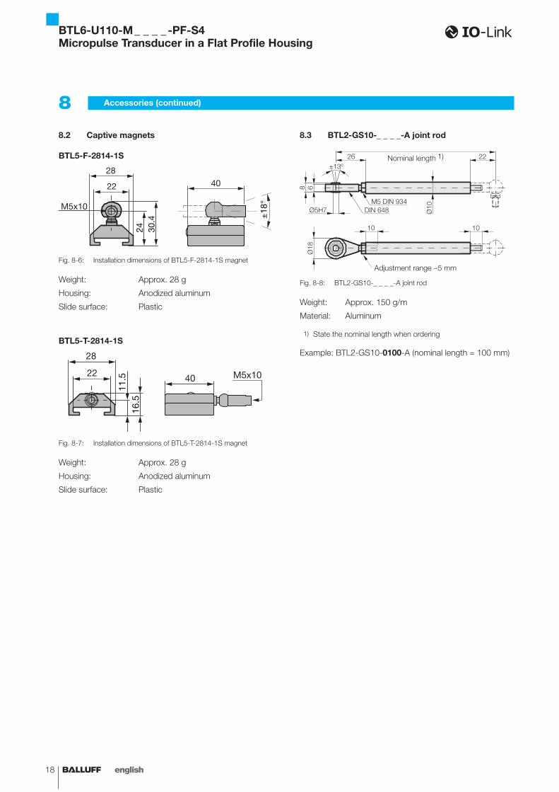
8.2 Captive magnets
BTL5-F-2814-1S30
.4
28
22
M5x10
±18
°
24
40
Fig. 8-6: Installation dimensions of BTL5-F-2814-1S magnet
Weight: Approx. 28 g
Housing: Anodized aluminum
Slide surface: Plastic
BTL5-T-2814-1S
16.5
11.5
28
22 40 M5x10
Fig. 8-7: Installation dimensions of BTL5-T-2814-1S magnet
Weight: Approx. 28 g
Housing: Anodized aluminum
Slide surface: Plastic
8.3 BTL2-GS10-_ _ _ _-A joint rod
Nominal length 1)
Adjustment range -5 mm
Fig. 8-8: BTL2-GS10-_ _ _ _-A joint rod
Weight: Approx. 150 g/m
Material: Aluminum
1) State the nominal length when ordering
Example: BTL2-GS10-0100-A (nominal length = 100 mm)
8 Accessories (continued)
BTL6-U110-M _ _ _ _ -PF-S4Micropulse Transducer in a Flat Profile Housing
www.balluff.com 19english
8 Accessories (continued)
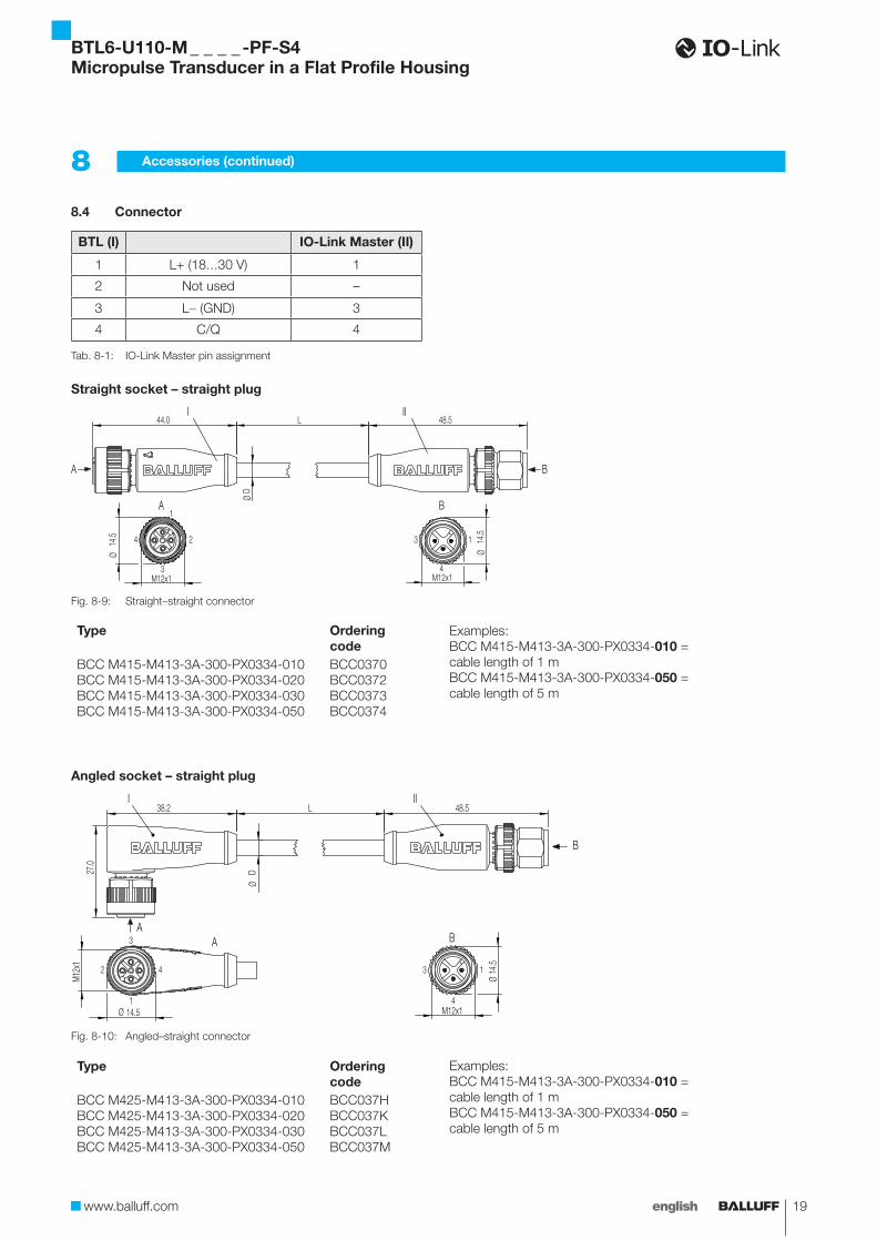
8.4 Connector
BTL (I) IO-Link Master (II)
1 L+ (18…30 V) 1
2 Not used –
3 L- (GND) 3
4 C/Q 4
Tab. 8-1: IO-Link Master pin assignment
Straight socket – straight plug
A
A B
B
I IIL44.0
ØD
Ø14
.5
M12x1
48.5
Ø14
.5
M12x1
1
4
4 2 3 1
3
Fig. 8-9: Straight–straight connector
Type Ordering code
BCC M415-M413-3A-300-PX0334-010BCC M415-M413-3A-300-PX0334-020BCC M415-M413-3A-300-PX0334-030BCC M415-M413-3A-300-PX0334-050
BCC0370BCC0372BCC0373BCC0374
Examples:BCC M415-M413-3A-300-PX0334-010 = cable length of 1 mBCC M415-M413-3A-300-PX0334-050 = cable length of 5 m
Angled socket – straight plug
B
AA
B
L38.2
27.0
ØD
I
M12x
1
Ø 14.5
48.5II
Ø14
.5
M12x1
4 3 12
3
1 4
Fig. 8-10: Angled–straight connector
Type Ordering code
BCC M425-M413-3A-300-PX0334-010BCC M425-M413-3A-300-PX0334-020BCC M425-M413-3A-300-PX0334-030BCC M425-M413-3A-300-PX0334-050
BCC037HBCC037KBCC037LBCC037M
Examples:BCC M415-M413-3A-300-PX0334-010 = cable length of 1 mBCC M415-M413-3A-300-PX0334-050 = cable length of 5 m
BTL6-U110-M _ _ _ _ -PF-S4Micropulse Transducer in a Flat Profile Housing
20 english
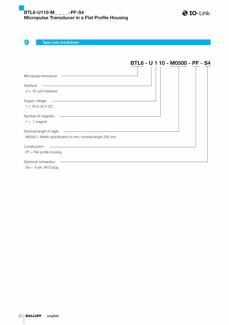
9 Type code breakdown
BTL6 - U 1 10 - M0500 - PF - S4
Micropulse transducer
Interface:
U = IO-Link interface
Supply voltage:
1 = 18 to 30 V DC
Number of magnets:
1 = 1 magnet
Nominal length (4-digit):
M0500 = Metric specification in mm, nominal length 500 mm
Construction:
PF = Flat profile housing
Electrical connection:
S4 = 4-pin, M12 plug
BTL6-U110-M _ _ _ _ -PF-S4Micropulse Transducer in a Flat Profile Housing
www.balluff.com 21english
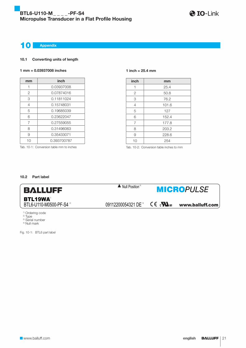
10.1 Converting units of length
1 mm = 0.03937008 inches
mm inch
1 0.03937008
2 0.07874016
3 0.11811024
4 0.15748031
5 0.19685039
6 0.23622047
7 0.27559055
8 0.31496063
9 0.35433071
10 0.393700787
Tab. 10-1: Conversion table mm to inches
1 inch = 25.4 mm
inch mm
1 25.4
2 50.8
3 76.2
4 101.6
5 127
6 152.4
7 177.8
8 203.2
9 228.6
10 254
Tab. 10-2: Conversion table inches to mm
10 Appendix
10.2 Part label
Fig. 10-1:
BTL19WABTL6-U110-M0500-PF-S4 09112200054321 DE
Null Position
BTL6 part label
1) Ordering code2) Type3) Serial number4) Null mark
1)
3) 2)
4)
BTL6-U110-M _ _ _ _ -PF-S4Micropulse Transducer in a Flat Profile Housing

No.
891
248-
726
E .
00.0
0000
0 . E
ditio
n 12
09;
Sub
ject
to m
odifi
catio
n.
www.balluff.com
Headquarters
GermanyBalluff GmbHSchurwaldstrasse 973765 Neuhausen a.d.F.Phone + 49 7158 173-0Fax +49 7158 [email protected]
Global Service Center
GermanyBalluff GmbHSchurwaldstrasse 973765 Neuhausen a.d.F.Phone +49 7158 173-370Fax +49 7158 [email protected]
US Service Center
USABalluff Inc.8125 Holton DriveFlorence, KY 41042Phone (859) 727-2200Toll-free 1-800-543-8390Fax (859) 727-4823 [email protected]
CN Service Center
ChinaBalluff (Shanghai) trading Co., ltd.Room 1006, Pujian Rd. 145. Shanghai, 200127, P.R. China Phone +86 (21) 5089 9970Fax +86 (21) 5089 [email protected]