BSc in Telecommunication Engineering TEL3214 … · 8-4 TEL3214 – Computer Communication Networks...
44
BSc in Telecommunication Engineering TEL3214 Computer Communication Networks Lecture 08 Transmission Media Wireless LANs Eng Diarmuid O'Briain, CEng, CISSP
Transcript of BSc in Telecommunication Engineering TEL3214 … · 8-4 TEL3214 – Computer Communication Networks...
BSc in Telecommunication EngineeringTEL3214Computer Communication Networks
Lecture 08
Transmission Media
Wireless LANs
Eng Diarmuid O'Briain, CEng, CISSP
8-2 TEL3214 – Computer Communication Networks
Copyright © 2016 Diarmuid Ó Briain
Permission is granted to copy, distribute and/or modify this document under the terms of theGNU Free Documentation License, Version 1.3 or any later version published by the FreeSoftware Foundation; with no Invariant Sections, no Front-Cover Texts, and no Back-CoverTexts. A copy of the license is included in the section entitled "GNU Free DocumentationLicense".
TEL3214 Wireless LAN (WLAN) 25 Apr 2016
TEL3214 – Computer Communication Networks 8-3
Table of Contents1. WIRELESS LANS..........................................................................................................................................5
1.1 ORGANISATIONS IMPACTING WI-FI IMPLEMENTATION.......................................................................................6
2. SETUP AN AD-HOC NETWORK...............................................................................................................72.1 CONFIGURING AN AD-HOC NETWORK.................................................................................................................72.2 MICROSOFT WINDOWS WORKSTATION..............................................................................................................82.3 UNIX / LINUX WORKSTATION..........................................................................................................................11
3. LAB EXERCISE – BUILDING A AD-HOC WIRELESS LAN...............................................................123.1 OBJECTIVE........................................................................................................................................................123.2 BACKGROUND...................................................................................................................................................123.3 LAB STEPS........................................................................................................................................................12
4. WIFI ORGANISATIONS.............................................................................................................................134.1 WI-FI ALLIANCE................................................................................................................................................134.2 INTERNATIONAL TELECOMMUNICATION UNION (ITU)......................................................................................144.3 FEDERAL COMMUNICATIONS COMMISSION (FCC)..........................................................................................14
5. WIRELESS LAN (WIFI) TECHNOLOGY................................................................................................155.1 SPREAD SPECTRUM..........................................................................................................................................155.2 POWER..............................................................................................................................................................165.3 RAKE RECEIVERS............................................................................................................................................165.4 IMPLEMENTING SPREAD SPECTRUM.................................................................................................................165.5 FREQUENCY HOPPING SPREAD SPECTRUM (FHSS)......................................................................................175.6 DIRECT SEQUENCE SPREAD SPECTRUM (DSSS)...........................................................................................175.7 ORTHOGONAL FREQUENCY DIVISION MULTIPLEXING (OFDM).......................................................................195.8 MULTIPLE-INPUT MULTIPLE-OUTPUT (MIMO) ANTENNA................................................................................215.9 802.11B/G/N.....................................................................................................................................................225.10 802.11A/N – 5 GHZ.......................................................................................................................................235.11 IEEE 802.11 FAMILY SUMMARY....................................................................................................................24
6. IEEE 802.11 WIRELESS LAN (WI-FI).....................................................................................................256.1 802.11 MAC (MEDIA ACCESS CONTROL).......................................................................................................256.2 ACKING............................................................................................................................................................ 266.3 MAC LEVEL RETRANSMISSION.........................................................................................................................266.4 FRAGMENTATION..............................................................................................................................................266.5 WI-FI ELEMENTS...............................................................................................................................................26
7. WI-FI SECURITY.........................................................................................................................................287.1 TYPES OF WI-FI SECURITY BREACHES............................................................................................................287.2 METHODS OF COUNTERACTING SECURITY RISKS............................................................................................307.3 WIRELESS ENCRYPTION PROTOCOL (WEP)...................................................................................................317.4 WI-FI PROTECTED ACCESS (WPA).................................................................................................................327.5 802.11I WPA2.................................................................................................................................................34
8. NON WI-FI SOLUTIONS IN UNLICENSED SPECTRUM...................................................................358.1 MIKROTIK - NSTREME / NV2............................................................................................................................358.2 NSTREME..........................................................................................................................................................358.3 NSTREME 2.......................................................................................................................................................358.4 NV2 (NSTREME VERSION 2).............................................................................................................................35
9. WIRELESS LAN LAB.................................................................................................................................369.1 CONFIGURATION OF WLAN1.............................................................................................................................379.2 CONFIGURATION OF SVR1................................................................................................................................379.3 CONFIGURATION OF RTR1................................................................................................................................389.4 CONFIGURATION OF RTR2................................................................................................................................399.5 CONFIGURATION OF RTR3................................................................................................................................40
10. SELF-TEST QUIZ......................................................................................................................................43
25 Apr 2016 Wireless LAN (WLAN) TEL3214
8-4 TEL3214 – Computer Communication Networks
Illustration IndexIllustration 1: MikroTik Wireless Devices..........................................................................................5Illustration 2: Ad-hoc network.............................................................................................................7Illustration 3: Microsoft Windows Ad-hoc network...........................................................................8Illustration 4: Microsoft Windows Ad-hoc network #2......................................................................9Illustration 5: Microsoft Windows - set IP address...........................................................................9Illustration 6: Microsoft Windows IP Address.................................................................................10Illustration 7: Ad-hoc network lab.....................................................................................................12Illustration 8: Wireless governing bodies.........................................................................................13Illustration 9: Spread spectrum........................................................................................................15Illustration 10: Spread Spectrum Spreader/Correlator..................................................................16Illustration 11: Spread spectrum techniques..................................................................................17Illustration 12: Operation of Direct Sequence Spread Spectrum..................................................18Illustration 13: OFDM Technique.....................................................................................................19Illustration 14: MIMO.........................................................................................................................21Illustration 15: 2.4 GHz Wi-Fi channels...........................................................................................22Illustration 16: 5 GHz classes and frequencies..............................................................................23Illustration 17: IEEE 802.1 Family Summary...................................................................................24Illustration 18: WLAN in the OSI Physical & Data Link Layers.....................................................25Illustration 19: Wireless Encryption Standard.................................................................................31Illustration 20: IEEE 802.1X..............................................................................................................33Illustration 21: 802.11i WPA2...........................................................................................................34Illustration 22: Wireless LAN Lab....................................................................................................36Illustration 23: Configuration of wlan1.............................................................................................37
TEL3214 Wireless LAN (WLAN) 25 Apr 2016
TEL3214 – Computer Communication Networks 8-5
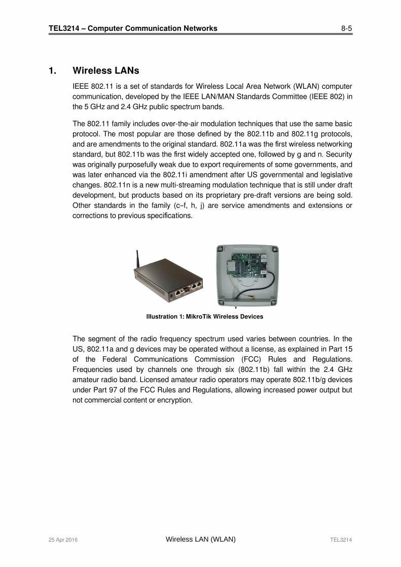
1. Wireless LANs
IEEE 802.11 is a set of standards for Wireless Local Area Network (WLAN) computercommunication, developed by the IEEE LAN/MAN Standards Committee (IEEE 802) inthe 5 GHz and 2.4 GHz public spectrum bands.
The 802.11 family includes over-the-air modulation techniques that use the same basicprotocol. The most popular are those defined by the 802.11b and 802.11g protocols,and are amendments to the original standard. 802.11a was the first wireless networkingstandard, but 802.11b was the first widely accepted one, followed by g and n. Securitywas originally purposefully weak due to export requirements of some governments, andwas later enhanced via the 802.11i amendment after US governmental and legislativechanges. 802.11n is a new multi-streaming modulation technique that is still under draftdevelopment, but products based on its proprietary pre-draft versions are being sold.Other standards in the family (c–f, h, j) are service amendments and extensions orcorrections to previous specifications.
The segment of the radio frequency spectrum used varies between countries. In theUS, 802.11a and g devices may be operated without a license, as explained in Part 15of the Federal Communications Commission (FCC) Rules and Regulations.Frequencies used by channels one through six (802.11b) fall within the 2.4 GHzamateur radio band. Licensed amateur radio operators may operate 802.11b/g devicesunder Part 97 of the FCC Rules and Regulations, allowing increased power output butnot commercial content or encryption.
25 Apr 2016 Wireless LAN (WLAN) TEL3214
Illustration 1: MikroTik Wireless Devices
8-6 TEL3214 – Computer Communication Networks
1.1 Organisations impacting Wi-Fi implementation
1.1.1 Institute of Electrical and Electronics Engineers
The IEEE has long been at the forefront of LAN standards and Wi-Fi standards comeunder the umbrella of the IEEE 802.11 standards. 802.11 refers to a family ofspecifications developed by the IEEE for wireless LAN technology. 802.11 specifies anover-the-air interface between a wireless client and a base station or between twowireless clients. The IEEE accepted the specification in 1997.
There are several specifications in the 802.11 family:
1 802.11 - applies to wireless LANs and provides 1 or 2 Mbps transmission in the2.4 GHz band using either Frequency Hopping Spread Spectrum (FHSS) orDirect Sequence Spread Spectrum (DSSS).
2 802.11a - an extension to 802.11 that applies to wireless LANs and provides
typically 25 Mbps to a maximum of 54 Mbps in the 5GHz band. 802.11a usesan Orthogonal Frequency Division Multiplexing (OFDM) encoding schemerather than FHSS or DSSS. Max range is 30 M.
3 802.11b - (also referred to as 802.11 High Rate or Wi-Fi) -- an extension to802.11 that applies to wireless LANS and provides 11 Mbps transmission (witha fallback to 5.5, 2 and 1 Mbps) in the 2.4 GHz band. 802.11b uses only DSSS.802.11b was a 1999 ratification to the original 802.11 standard, allowingwireless functionality comparable to Ethernet. Max range is 30 M.
4 802.11g - applies to wireless LANs and provides typically 24 Mbps to amaximum of 54 Mbps in the 2.4 GHz band. It also uses OFDM. Max range is 30M.
5 802.11n - 200 Mbps standard to a maximum of 540 Mbps out to 50 M in eitherthe 2.4 or 5 GHz bands. It uses Multiple In, Multiple Out (MIMO) antennas.
6 802.11ac – The latest standard which gives multi-station WLAN throughput ofat least 1 Gb/s and a single link throughput of at least 500 Mb/s. This isachieved by extending the air interface concepts embraced by 802.11n, usingwider RF bandwidth of up to 160 MHz, up to 8 MIMO spatial streams, up to 4downlink multi-user MIMO clients, and 256 QAM high-density modulation.
TEL3214 Wireless LAN (WLAN) 25 Apr 2016
TEL3214 – Computer Communication Networks 8-7
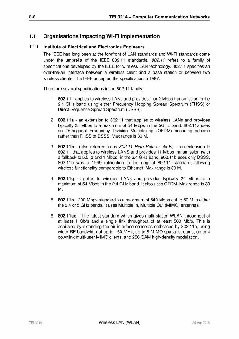
2. Setup an Ad-hoc network
An ad hoc network is a temporary connection between computers and devices used fora specific purpose, such as sharing documents during a meeting or playing multiple-player computer games. You can also use an ad hoc network to temporarily share anInternet connection. Ad hoc networks can only be wireless, so you must have a wirelessnetwork adapter installed in your computer to set up or join an ad hoc network.
Illustration 2: Ad-hoc network
2.1 Configuring an ad-hoc network To do this you will need the following information.
SSID to share on ad-hoc network
Key IP Address of workstation.
Subnetmask for the network the workstation is participating.
IP Address of the router interface on the network (Default Gateway)
Domain Name Server IP Address. This is the server that will convert domainnames to IP Address for the workstation on request.
25 Apr 2016 Wireless LAN (WLAN) TEL3214
192.168.100.66
192.168.100.65
Wireless Network
192.168.100.67
8-8 TEL3214 – Computer Communication Networks
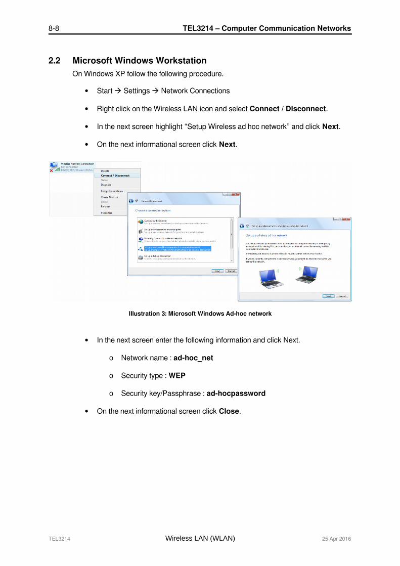
2.2 Microsoft Windows WorkstationOn Windows XP follow the following procedure.
Start Settings Network Connections
Right click on the Wireless LAN icon and select Connect / Disconnect.
In the next screen highlight “Setup Wireless ad hoc network” and click Next.
On the next informational screen click Next.
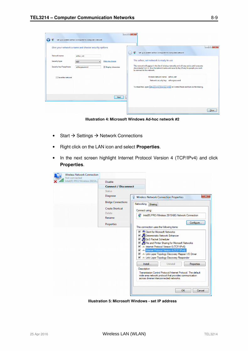
In the next screen enter the following information and click Next.
o Network name : ad-hoc_net
o Security type : WEP
o Security key/Passphrase : ad-hocpassword
On the next informational screen click Close.
TEL3214 Wireless LAN (WLAN) 25 Apr 2016
Illustration 3: Microsoft Windows Ad-hoc network
TEL3214 – Computer Communication Networks 8-9
Illustration 4: Microsoft Windows Ad-hoc network #2
Start Settings Network Connections
Right click on the LAN icon and select Properties.
In the next screen highlight Internet Protocol Version 4 (TCP/IPv4) and clickProperties.
Illustration 5: Microsoft Windows - set IP address
25 Apr 2016 Wireless LAN (WLAN) TEL3214

8-10 TEL3214 – Computer Communication Networks
In the next screen highlight Internet Protocol Version 4 (TCP/IPv4) and clickProperties.
Illustration 6: Microsoft Windows IP Address
Filling the IP Address, Subnetmask, Default Gateway such that it will match thaton the other side of the ad-hoc connection and click OK.
Notes:
An ad hoc network is automatically deleted after all users disconnect from the networkor when the person who set up the network disconnects and goes out of range of theother users of the network, unless you choose to make it a permanent network whenyou create it.
If you do not configure IP Address on Windows, a 169. Address will be automaticallyassigned by the Operating System.
TEL3214 Wireless LAN (WLAN) 25 Apr 2016
TEL3214 – Computer Communication Networks 8-11
2.3 UNIX / Linux WorkstationOn UNIX and Linux you can use the graphical tools on the system you use or you canuse the commands in the shell. You must be logged in as the “root” user to havepermissions to make these changes.
2.3.1 Gnome Desktop
The UNIX or Linux Gnome Desktop does not have a method of configuring an ad-hocnetwork, however it is configurable using the iwconfig command.
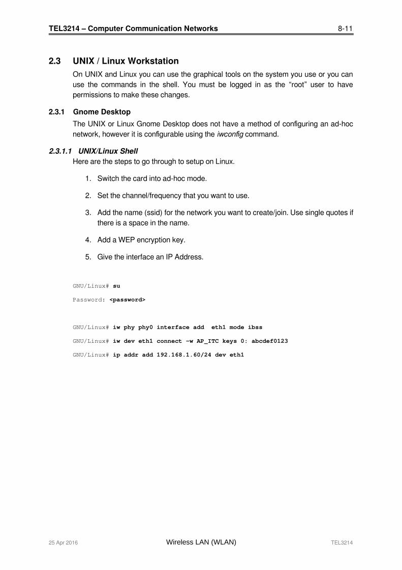
2.3.1.1 UNIX/Linux ShellHere are the steps to go through to setup on Linux.
1. Switch the card into ad-hoc mode.
2. Set the channel/frequency that you want to use.
3. Add the name (ssid) for the network you want to create/join. Use single quotes ifthere is a space in the name.
4. Add a WEP encryption key.
5. Give the interface an IP Address.
GNU/Linux# su
Password: <password>
GNU/Linux# iw phy phy0 interface add eth1 mode ibss
GNU/Linux# iw dev eth1 connect -w AP_ITC keys 0: abcdef0123
GNU/Linux# ip addr add 192.168.1.60/24 dev eth1
25 Apr 2016 Wireless LAN (WLAN) TEL3214

8-12 TEL3214 – Computer Communication Networks
3. Lab Exercise – Building a ad-hoc Wireless LAN
3.1 Objective Practice building LANs.
Practice configuring Workstations for inclusion in a LAN.
3.2 Background Knowing how to build ad-hoc Wireless LAN is an essential building block to younetworking knowledge.
3.3 Lab Steps
3.3.1 Workstation Configuration
Use the notes to configure the workstations.
3.3.2 Test Configuration
Ping from one ad-hoc host to another ad-hoc host.
TEL3214 Wireless LAN (WLAN) 25 Apr 2016
Illustration 7: Ad-hoc network lab
192.168.100.66
192.168.100.65
Wireless Network
192.168.100.67

TEL3214 – Computer Communication Networks 8-13
4. WiFi Organisations
In 1999, several industry leaders came together to form a global, non-profit organisationwith the goal of driving the adoption of a single worldwide-accepted standard for high-speed wireless local area networking. We are that organisation. We are known as theWi-Fi Alliance.
Today, with more than 300 members from more than 20 countries and growing,common goals still bind us together.
Illustration 8: Wireless governing bodies
4.1 Wi-Fi AllianceAs Wi-Fi networks continue to expand through businesses, homes, and now publichotspots that provide wireless access locations for people on the go, compatibility iscritical. The Wi-Fi Alliance develops rigorous tests and conducts Wi-Fi certification ofwireless devices that implement the universal IEEE 802.11 specifications. The endresult leads to the confidence that both home and enterprise users need to continue toget the most out of Wi-Fi.
To date we have certified the interoperability of more than 3,500 products. There ismore, however, to Wi-Fi Alliance than interoperability. We work to provide Wi-Fi userswith the information they need to make decisions about today's Wi-Fi systems. Whetheryou are a tech-savvy IT director, a security-minded CIO, or a home user intrigued byWi-Fi possibilities, our aim is to provide the information you need to proceed withconfidence and peace of mind.
As the market continues to evolve, so will our efforts. We will continue to test and certifythe compatibility of Wi-Fi devices, we will take the lead in initiatives designed toenhance and simplify the user experience, we will provide thought leadership and up-to-date information, and we will continue to promote the standards that reduce costs - allin hopes of helping what was once a futuristic vision of Wi-Fi become a full-fledgedreality.
Although the terms 802.11 and Wi-Fi are often used interchangeably, the Wi-Fi Allianceuses the term "Wi-Fi" to define a slightly different set of overlapping standards. In somecases, market demand has led the Wi-Fi Alliance to begin certifying products beforeamendments to the 802.11 standard are complete.
25 Apr 2016 Wireless LAN (WLAN) TEL3214
8-14 TEL3214 – Computer Communication Networks
4.2 International Telecommunication Union (ITU)ITU is the leading United Nations agency for information and communicationtechnologies. As the global focal point for governments and the private sector, ITU'srole in helping the world communicate spans 3 core sectors: radio-communication,standardisation and development.
4.3 Federal Communications Commission (FCC) The FCC is an independent United States government agency, directly responsible tothe US Congress. The FCC was established by the Communications Act of 1934 and ischarged with regulating interstate and international communications by radio, television,wire, satellite and cable. The FCC's jurisdiction covers the 50 states, the District ofColumbia, and US possessions.
TEL3214 Wireless LAN (WLAN) 25 Apr 2016
TEL3214 – Computer Communication Networks 8-15
5. Wireless LAN (WiFi) Technology
In 1985, The Federal Communications Commission (FCC) in the USA authorised theuse of non-licensed spread spectrum systems in the 902-928 MHz, 2400-2483.5 MHz,and 5725-5850 MHz bands under Part 15 of the rules at a power level of 1W, whichwas significantly higher than previously permitted unlicensed use in other bands (FCC,1985).
An unlicensed device or Intentional radiators are devices that intentionally generate andemit Radio Frequency (RF) energy by radiation or induction. Such devices cannotcause interference to licensed operations nor are they protected from any interferencereceived (Marcus et al., 2002).
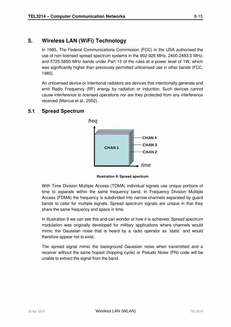
5.1 Spread Spectrum
Illustration 9: Spread spectrum
With Time Division Multiple Access (TDMA) individual signals use unique portions oftime to separate within the same frequency band. In Frequency Division MultipleAccess (FDMA) the frequency is subdivided into narrow channels separated by guardbands to cater for multiple signals. Spread spectrum signals are unique in that theyshare the same frequency and space in time.
In Illustration 9 we can see this and can wonder at how it is achieved. Spread spectrummodulation was originally developed for military applications where channels wouldmimic the Gaussian noise that is heard by a radio operator as ‘static’ and wouldtherefore appear not to exist.
The spread signal mimic the background Gaussian noise when transmitted and areceiver without the same hopset (hopping cycle) or Pseudo Noise (PN) code will beunable to extract the signal from the band.
25 Apr 2016 Wireless LAN (WLAN) TEL3214

8-16 TEL3214 – Computer Communication Networks
Illustration 10: Spread Spectrum Spreader/Correlator
In Illustration 10 it can be seen that the data for transmission is initially spread by aSpreader before being sent to the transmitter. The receiver with the same PN codeextracts the signal from the noise and using a circuit called a Correlator extracts theoriginal data signal.
5.2 PowerThe Spread Spectrum transmitter uses similar transmit power levels to narrow bandtransmitters, and they are said to be power neutral.
Total Power = Spectral density (W/Hz) x Bandwidth
and as the spectral density of spread spectrum signal will be much lower consideringthe wider frequency band for the same total power. The power at any point in the signalis much lower for a comparable narrow band transmission. This can be seen clearly inIllustration 11(b) where the spread signal appears at the same power level as thebackground Gaussian noise.
5.3 RAKE ReceiversAt the receiver the multipath spread signal is extracted using RAKE receivers. A RAKEreceiver consists of multiple correlators (fingers on a rake) where each of the fingerscan detect/extract the signal from one of the multipath components created by thespread signal. The outputs of the fingers are then combined to recover the signal.
5.4 Implementing Spread SpectrumThe two primary methods used to spread the baseband data spectrum are:
Frequency Hopping Spread Spectrum (FHSS)
Direct Sequence Spread Spectrum (DSSS)
TEL3214 Wireless LAN (WLAN) 25 Apr 2016
TEL3214 – Computer Communication Networks 8-17
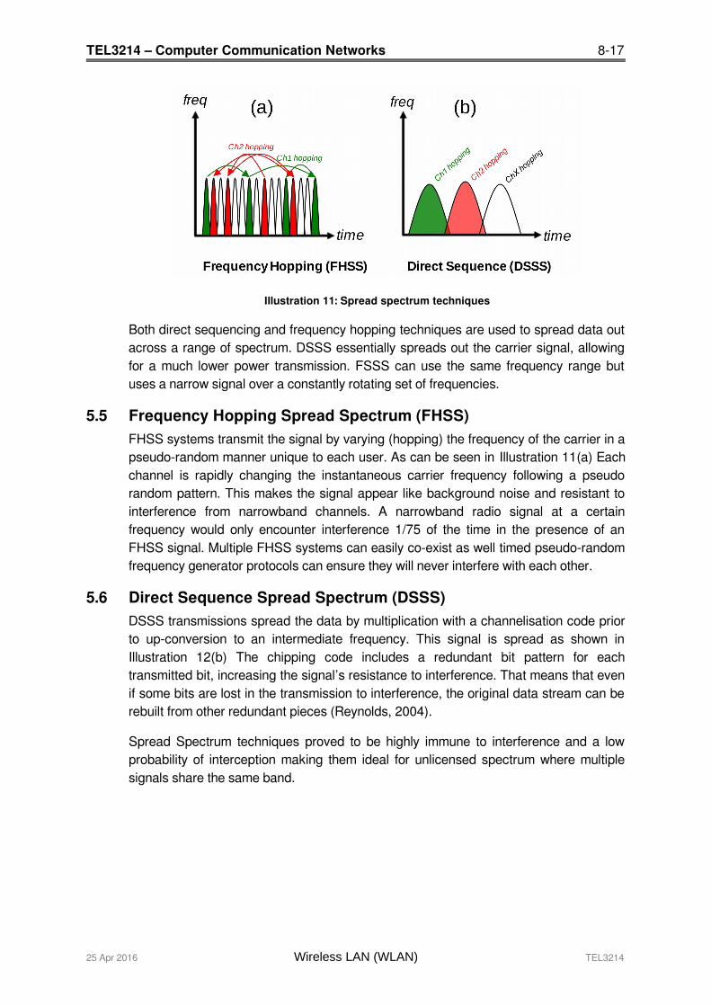
Illustration 11: Spread spectrum techniques
Both direct sequencing and frequency hopping techniques are used to spread data outacross a range of spectrum. DSSS essentially spreads out the carrier signal, allowingfor a much lower power transmission. FSSS can use the same frequency range butuses a narrow signal over a constantly rotating set of frequencies.
5.5 Frequency Hopping Spread Spectrum (FHSS)FHSS systems transmit the signal by varying (hopping) the frequency of the carrier in apseudo-random manner unique to each user. As can be seen in Illustration 11(a) Eachchannel is rapidly changing the instantaneous carrier frequency following a pseudorandom pattern. This makes the signal appear like background noise and resistant tointerference from narrowband channels. A narrowband radio signal at a certainfrequency would only encounter interference 1/75 of the time in the presence of anFHSS signal. Multiple FHSS systems can easily co-exist as well timed pseudo-randomfrequency generator protocols can ensure they will never interfere with each other.
5.6 Direct Sequence Spread Spectrum (DSSS) DSSS transmissions spread the data by multiplication with a channelisation code priorto up-conversion to an intermediate frequency. This signal is spread as shown inIllustration 12(b) The chipping code includes a redundant bit pattern for eachtransmitted bit, increasing the signal’s resistance to interference. That means that evenif some bits are lost in the transmission to interference, the original data stream can berebuilt from other redundant pieces (Reynolds, 2004).
Spread Spectrum techniques proved to be highly immune to interference and a lowprobability of interception making them ideal for unlicensed spectrum where multiplesignals share the same band.
25 Apr 2016 Wireless LAN (WLAN) TEL3214
8-18 TEL3214 – Computer Communication Networks
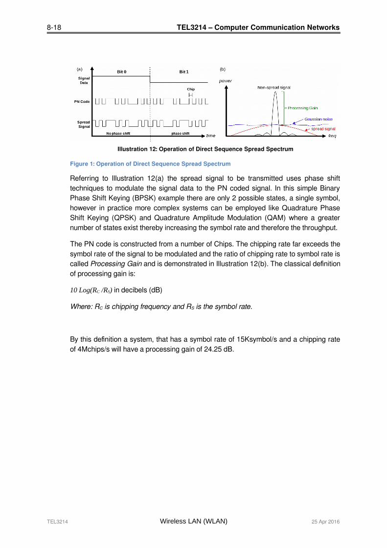
Illustration 12: Operation of Direct Sequence Spread Spectrum
Figure 1: Operation of Direct Sequence Spread Spectrum
Referring to Illustration 12(a) the spread signal to be transmitted uses phase shifttechniques to modulate the signal data to the PN coded signal. In this simple BinaryPhase Shift Keying (BPSK) example there are only 2 possible states, a single symbol,however in practice more complex systems can be employed like Quadrature PhaseShift Keying (QPSK) and Quadrature Amplitude Modulation (QAM) where a greaternumber of states exist thereby increasing the symbol rate and therefore the throughput.
The PN code is constructed from a number of Chips. The chipping rate far exceeds thesymbol rate of the signal to be modulated and the ratio of chipping rate to symbol rate iscalled Processing Gain and is demonstrated in Illustration 12(b). The classical definitionof processing gain is:
10 Log(RC /RS) in decibels (dB)
Where: RC is chipping frequency and RS is the symbol rate.
By this definition a system, that has a symbol rate of 15Ksymbol/s and a chipping rateof 4Mchips/s will have a processing gain of 24.25 dB.
TEL3214 Wireless LAN (WLAN) 25 Apr 2016

TEL3214 – Computer Communication Networks 8-19
5.7 Orthogonal Frequency Division Multiplexing (OFDM)
Illustration 13: OFDM Technique
OFDM is a particular form of Frequency Division Multiplex (FDM) where a datastreamis transmitted over a number of low rate subcarriers. Unlike FDM instead of having thechannels non overlapping as shown in Illustration 13 (b) OFDM makes more efficientuse of spectrum by over-lapping the channels. This can only be achieved by reducingcrosstalk between the carriers using a precise mathematical relationship between thefrequencies, an orthogonal relationship. The sub-carrier frequencies are chosen so thatthe sub-carriers are orthogonal to each other, meaning that cross-talk between the sub-channels is eliminated and inter-carrier guard bands are not required.
To use OFDM the data to be transmitted is broken down into several streams that arebroadcast simultaneously, on different frequencies, to a receiver that collects andreassembles them which makes it less susceptible to multipath and other radiointerference.
This greatly simplifies the design of both the transmitter and the receiver; unlikeconventional Frequency Division Multiplex (FDM), a separate filter for each sub-channelis not required. Each sub-carrier is modulated with a conventional modulation schemesuch as QAM at a low symbol rate, maintaining data rates similar to conventionalsingle-carrier modulation schemes in the same bandwidth.
25 Apr 2016 Wireless LAN (WLAN) TEL3214
8-20 TEL3214 – Computer Communication Networks
The primary advantage of OFDM over single-carrier schemes is its ability to cope withsevere channel conditions — for example, attenuation of high frequencies at a longcopper wire, narrowband interference and frequency-selective fading due to multipathwithout complex equalisation filters. Channel equalisation is simplified because OFDMmay be viewed as using many slowly-modulated narrowband signals rather than onerapidly-modulated wideband signal. Low symbol rate makes the use of a guard intervalbetween symbols affordable, making it possible to handle time-spreading and eliminateInter Symbol Interference (ISI).
OFDM has developed into a popular scheme for wideband digital communicationsystems.
5.7.1 Summary of advantages
Can easily adapt to severe channel conditions without complex equalisation Robust against narrow-band co-channel interference Robust against ISI and fading caused by multipath propagation High spectral efficiency Efficient implementation using Fast Fourier Transform (FFT) Low sensitivity to time synchronisation errors Tuned sub-channel receiver filters are not required (unlike conventional FDM) Facilitates Single Frequency Networks, i.e. transmitter macro-diversity.
TEL3214 Wireless LAN (WLAN) 25 Apr 2016

TEL3214 – Computer Communication Networks 8-21
5.8 Multiple-Input Multiple-Output (MIMO) Antenna
Illustration 14: MIMO
A MIMO antenna array is a set of antenna’s at both ends of a link. The reasons fordoing this are varied and a number of modes have evolved giving performanceenhancements such as transmit-receive diversity and spatial multiplexing.
Diversity refers to the use of multiple antennas to increase the probability of a highquality signal path between the sender and the receiver. Referring to Illustration 14 (a)the transmitted signal follows multiple paths to the receiver with elements arriving atslightly out of phase from each other. The receiver can apply advanced signalprocessing algorithms to combine the different versions of the received signals tomaximise Signal to Noise Ratio (SNR).
As can be seen from the diagram Illustration 14 (b) Spatial Division Multiplexing (SDM)allows the sender to transmit different portions of the user data on multiple paths inparallel to increase capacity.
25 Apr 2016 Wireless LAN (WLAN) TEL3214
8-22 TEL3214 – Computer Communication Networks
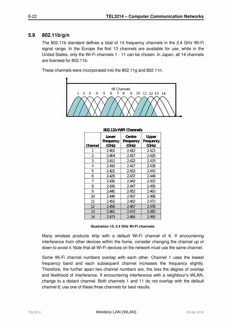
5.9 802.11b/g/nThe 802.11b standard defines a total of 14 frequency channels in the 2.4 GHz Wi-Fisignal range. In the Europe the first 13 channels are available for use, while in theUnited States, only the Wi-Fi channels 1 - 11 can be chosen. In Japan, all 14 channelsare licensed for 802.11b.
These channels were incorporated into the 802.11g and 802.11n.
Illustration 15: 2.4 GHz Wi-Fi channels
Many wireless products ship with a default Wi-Fi channel of 6. If encounteringinterference from other devices within the home, consider changing the channel up ordown to avoid it. Note that all Wi-Fi devices on the network must use the same channel.
Some Wi-Fi channel numbers overlap with each other. Channel 1 uses the lowestfrequency band and each subsequent channel increases the frequency slightly.Therefore, the further apart two channel numbers are, the less the degree of overlapand likelihood of interference. If encountering interference with a neighbour’s WLAN,change to a distant channel. Both channels 1 and 11 do not overlap with the defaultchannel 6; use one of these three channels for best results.
TEL3214 Wireless LAN (WLAN) 25 Apr 2016

TEL3214 – Computer Communication Networks 8-23
5.10 802.11a/n – 5 GHz802.11a defines the physical air interface for up to 200 channels in the 5 GHzunlicensed spectrum with a channel size of 20 MHz. Channel centre frequency for eachchannel can be calculated by the formula 5000 + 5 × Nch (MHz) where Nch = 0 - 200.
It is based on an OFDM implementation using 52 subcarriers that are modulated usingBPSK, QPSK, 16-QAM, or 64-QAM. 802.11a has data throughput capabilities of 6, 9,12, 18, 24, 36, 48, and 54 Mbit/s.
These channels were incorporated into the higher speed 802.11n standard and are thechannels used in the newer 802.11ac standard.
Regulatory Channel Channel Channel FrequenciesClass starting Spacing set (GHz)
frequency (MHz)
1 5 20
36 5.18040 5.20044 5.22048 5.240
2 5 20
52 5.26056 5.28060 5.30064 5.320
3 5 20
100 5.500104 5.520108 5.540112 5.560116 5.580120 5.600124 5.620128 5.640132 5.660136 5.680140 5.700
Illustration 16: 5 GHz classes and frequencies
In some countries wideband data transmission systems for the provision of FixedWireless Access Networks/Metropolitan Area Networks (FWA/MAN) is also permittedin the 5.8GHz (5725 – 5875MHz) band up to a maximum radiated power of 2WEffective Isotropic Radiated Power (EIRP) on a licence exempt basis. This gives anadditional 7 20 MHz channels. 5.745, 5.765, 5.785, 5.805, 5.825, 5.845, 5.865 GHz.
25 Apr 2016 Wireless LAN (WLAN) TEL3214

8-24 TEL3214 – Computer Communication Networks
5.11 IEEE 802.11 Family Summary
IEEEDesignatio
nModulation
MaxSpeed
OperatingFrequency
Non-overlappingchannels
Antenna
Range
Indoor Outdoor
802.11b DSSS 11Mbps
2.4 GHz 3 ~38 M ~140 M
802.11a OFDM 54Mbps
5 GHz 12 ~35 M ~120 M
802.11g OFDM 54Mbps
2.4 GHz 3 ~35 M ~140 M
802.11n OFDM 248Mbps
2.4 (5)GHz
3 (12 **) MIMO ~70 M ~250 M
802.11ac OFDM 1 Gbps 5 GHz 12 ** MIMO ~35 M
Illustration 17: IEEE 802.1 Family Summary
** at 20 Mhz channel sizes, technology allows for larger channel sizes which obviously reduces the number of available channels.
TEL3214 Wireless LAN (WLAN) 25 Apr 2016
TEL3214 – Computer Communication Networks 8-25
6. IEEE 802.11 Wireless LAN (Wi-Fi)
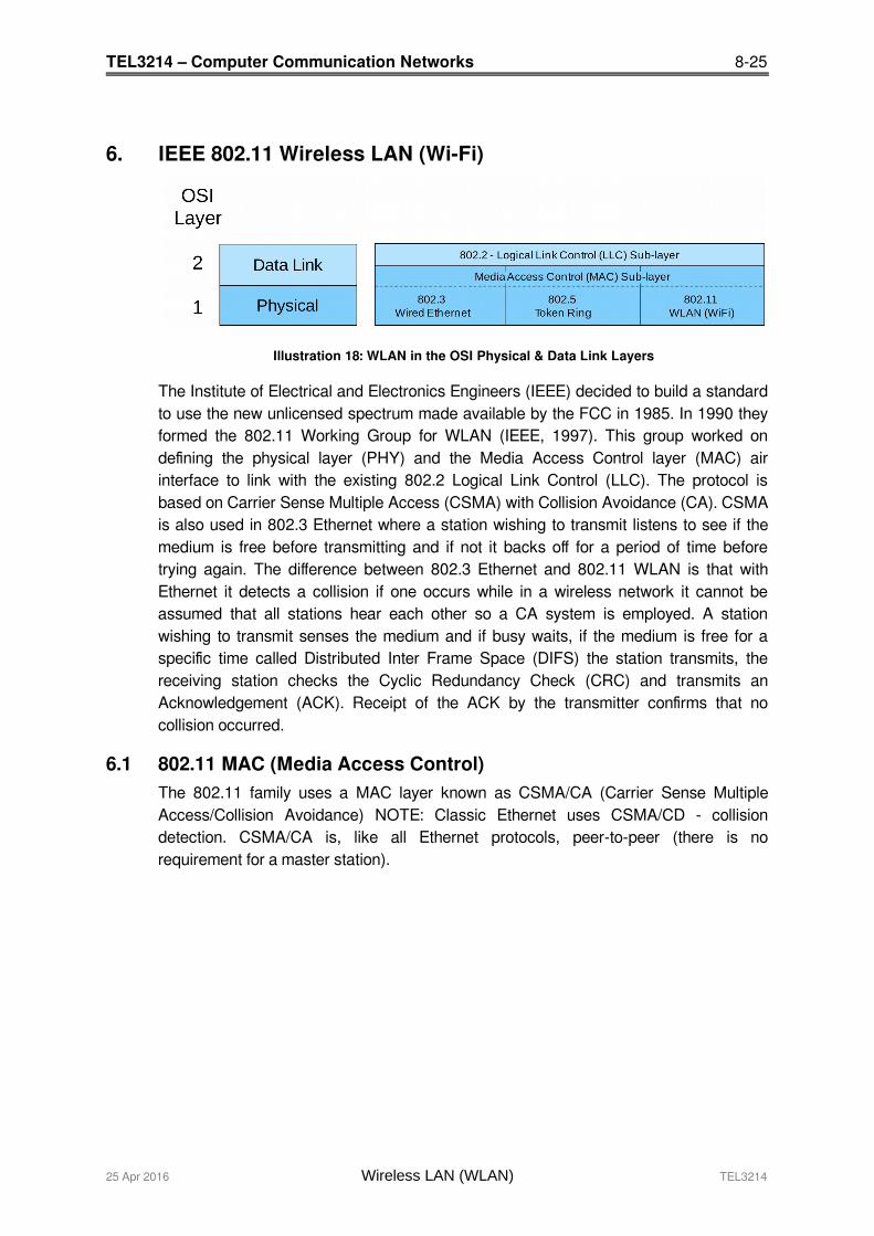
Illustration 18: WLAN in the OSI Physical & Data Link Layers
The Institute of Electrical and Electronics Engineers (IEEE) decided to build a standardto use the new unlicensed spectrum made available by the FCC in 1985. In 1990 theyformed the 802.11 Working Group for WLAN (IEEE, 1997). This group worked ondefining the physical layer (PHY) and the Media Access Control layer (MAC) airinterface to link with the existing 802.2 Logical Link Control (LLC). The protocol isbased on Carrier Sense Multiple Access (CSMA) with Collision Avoidance (CA). CSMAis also used in 802.3 Ethernet where a station wishing to transmit listens to see if themedium is free before transmitting and if not it backs off for a period of time beforetrying again. The difference between 802.3 Ethernet and 802.11 WLAN is that withEthernet it detects a collision if one occurs while in a wireless network it cannot beassumed that all stations hear each other so a CA system is employed. A stationwishing to transmit senses the medium and if busy waits, if the medium is free for aspecific time called Distributed Inter Frame Space (DIFS) the station transmits, thereceiving station checks the Cyclic Redundancy Check (CRC) and transmits anAcknowledgement (ACK). Receipt of the ACK by the transmitter confirms that nocollision occurred.
6.1 802.11 MAC (Media Access Control)The 802.11 family uses a MAC layer known as CSMA/CA (Carrier Sense MultipleAccess/Collision Avoidance) NOTE: Classic Ethernet uses CSMA/CD - collisiondetection. CSMA/CA is, like all Ethernet protocols, peer-to-peer (there is norequirement for a master station).
25 Apr 2016 Wireless LAN (WLAN) TEL3214

8-26 TEL3214 – Computer Communication Networks
In CSMA/CA a Wireless node that wants to transmit performs the following sequence:
Listen on the desired channel. If channel is idle (no active transmitters) it sends a packet. If channel is busy (an active transmitter) node waits until transmission stops
then a further CONTENTION period. (The Contention period is a random periodafter every transmit on every node and statistically allows every node equalaccess to the media. To allow TX to RX turn around the contention time isslotted 50 micro sec for FH and 20 micro sec for Direct Sequence (DS)systems).
If the channel is still idle at the end of the CONTENTION period the nodetransmits its packet otherwise it repeats the process defined in 3 above until itgets a free channel.
6.2 ACKingAt the end of every packet the receiver, if it has successfully received the packet, willreturn an ACK packet (if not received or received with errors the receiver will NOTrespond i.e. there is no NACK). The transmit window allows for the ACK i.e.CONTENTION period starts after the ACK should have been sent.
6.3 MAC level retransmissionIf no ACK is received the sender will retry the transmit (using the normal CSMA/CAprocedures) until either successful or the operation is abandoned with exhaustedretries.
6.4 FragmentationBit error rates on wireless systems (10-5, 10-6) are substantially higher than wire-linesystems (10-12). Large blocks may approach the number of bits where the probability ofan error occurring is so high that every block could fail including the re-transmission. Toreduce the possibility of this happening large blocks may be fragmented by thetransmitter and reassembled by the receiver node e.g. a 1500 byte block (12,000 bits)may be fragmented into 5 blocks of 300 bytes (2,400 bits). While there is someoverhead in doing this - both the probability of an error occurring is reduced and, in theevent of an error, the re-transmission time is also reduced.
6.5 Wi-Fi Elements802.11 networks are organised in one of these ways:
1. In infrastructure mode one station acts as a master with all the other stationsassociating to it; the network is known as a Basic Service Set (BSS) and themaster station is termed an AP. In a BSS all communication passes through theAP; even when one station wants to communicate with another wireless stationmessages must go through the AP.
2. An Extended Service Set (ESS) is one or more interconnected BSSs and theirassociated LANs. To the logical link control layer the ESS appears as a solitaryBSS at any one of the STAs.
3. In the second form of network there is no master and stations communicatedirectly. This form of network is termed an Independent Basic Service Set (IBSS)and is commonly known as an ad-hoc network.
TEL3214 Wireless LAN (WLAN) 25 Apr 2016
TEL3214 – Computer Communication Networks 8-27
6.5.1 Wireless Access Point (AP)
The Wireless Access Point is the hub of a wireless network. Wireless clients connect tothe access point, and traffic between two clients must travel through the access point.Access Points are often abbreviated to AP, and you may also see them referred to as"wireless routers," "wireless gateways," and "base stations."
6.5.2 Service Set IDentifier (SSID)
An SSID is a secret key attached to all packets on a wireless network to identify eachpacket as part of that network. The code consists of a string of 1-32 octets. All wirelessdevices attempting to communicate with each other must share the same SSID. Apartfrom identifying each packet, an SSID also serves to uniquely identify a group ofwireless network devices used in a given "Service Set".
There are two major variants of the SSID:
Ad-hoc wireless networks (IBSS) that consist of client machines without an accesspoint use the IBSS ID (Independent Basic Service Set Identifier)
Infrastructure networks which include an AP (BSS or possibly an ESS) use theBSS ID or ESS ID (instead.
The naming is for convention only as the IEEE 802.11 standard dictates that an IBSS,BSS, and ESS are each defined by an SSID, otherwise known as a "Network Name". ANetwork Name is commonly set to the name of the network operator, such as acompany name. Equipment manufacturers have liberally used all of the above SSIDnaming conventions to essentially describe the same thing. In some instances, theconvention is wrong, as in the case of BSSID.
The SSID on wireless clients can be set either manually, by entering the SSID into theclient network settings, or automatically, by leaving the SSID unspecified or blank. Anetwork administrator often uses a public SSID that is set on the access point andbroadcast to all wireless devices in range.
Most 802.11 access point vendors allow the use of an SSID of "any" to enable an802.11 NIC to connect to any 802.11 network.
6.5.3 Disabling SSID Broadcasting
Many Wireless Access Point (WAP) vendors have added a configuration option whichlets you disable broadcasting of the SSID. This adds little security because it is onlyable to prevent the SSID from being broadcast with Probe Request and Beacon frames.The SSID must be broadcast with Probe Response frames. In addition, the wirelessaccess cards will broadcast the SSID in their Association and Re-association frames.Because of this, the SSID cannot be considered a valid security tool.
25 Apr 2016 Wireless LAN (WLAN) TEL3214
8-28 TEL3214 – Computer Communication Networks
7. Wi-Fi Security
The ability to enter a network while mobile has great benefits. However, wirelessnetworking has many security issues. Hackers have found wireless networks relativelyeasy to break into, and even use wireless technology to crack into wired networks.
7.1 Types of Wi-Fi Security Breaches
7.1.1 Accidental association
When a user turns on a computer and it latches on to a wireless access point from aneighbouring company’s overlapping network, the user may not even know that this hasoccurred. However, it is a security breach in that proprietary company information isexposed and now there could exist a link from one company to the other.
7.1.2 Malicious association
“Malicious associations” are when wireless devices can be actively made by crackersto connect to a company network through their cracking laptop instead of a companyAP. These types of laptops are known as “soft APs” and are created when a crackerruns some software that makes his/her wireless network card look like a legitimateaccess point.
7.1.3 Ad-hoc networks
Ad-hoc networks can pose a security threat. Ad-hoc networks are defined as peer-to-peer networks between wireless computers that do not have an access point inbetween them. While these types of networks usually have little protection, encryptionmethods can be used to provide security.
7.1.4 Non-traditional networks
Non-traditional networks such as personal network Bluetooth devices are not safe fromcracking and should be regarded as a security risk. Even barcode readers, handheldPersonal Digital Assistants (PDA), and wireless printers and copiers should be secured.These non-traditional networks can be easily overlooked by IT personnel who havenarrowly focused on laptops and access points.
TEL3214 Wireless LAN (WLAN) 25 Apr 2016

TEL3214 – Computer Communication Networks 8-29
7.1.5 Identity theft (MAC spoofing)
Identity theft (or MAC spoofing) occurs when a cracker is able to listen in on networktraffic and identify the MAC address of a computer with network privileges. Mostwireless systems allow some kind of MAC filtering to only allow authorised computerswith specific MAC IDs to gain access and utilise the network. However, a number ofprograms exist that have network “sniffing” capabilities. Combine these programs withother software that allow a computer to pretend it has any MAC address that thecracker desires, and the cracker can easily get around that hurdle.
7.1.6 Man-in-the-middle attacks
A man-in-the-middle attacker entices computers to log into a computer which is set upas a soft AP. Once this is done, the hacker connects to a real access point throughanother wireless card offering a steady flow of traffic through the transparent hackingcomputer to the real network.
7.1.7 Denial of service (DoS)
A DoS occurs when an attacker continually bombards a targeted AP or network withbogus requests, premature successful connection messages, failure messages, and/orother commands. These cause legitimate users to not be able to get on the network andmay even cause the network to crash.
7.1.8 Network injection
In a network injection attack, a cracker can make use of access points that are exposedto non-filtered network traffic, specifically broadcast network traffic such as “SpanningTree” (802.1D), OSPF, RIP, Hot Standby Router Protocol (HSRP) and Virtual RouterRedundancy Protocol (VRRP). The cracker injects bogus networking re-configurationcommands that affect routers, switches, and intelligent hubs. A whole network can bebrought down in this manner and require rebooting or even reprogramming of allintelligent networking devices.
25 Apr 2016 Wireless LAN (WLAN) TEL3214

8-30 TEL3214 – Computer Communication Networks
7.2 Methods of counteracting security risksThere are many technologies available to counteract wireless network intrusion, butcurrently no method is absolutely secure. The best strategy may be to combine anumber of security measures.
There are three steps to take towards securing a wireless network:
1) All wireless LAN devices need to be secured.2) All users of the wireless network need to be educated in wireless network security.3) All wireless networks need to be actively monitored for weaknesses and breaches.
7.2.1 Steps in securing a wireless network
The following are some basic steps that are recommended to be taken to secure awireless network; in order of importance:
Turn on encryption. Wi-Fi Protected Access version 2 (WPA2) encryption shouldbe used if possible. Wi-Fi Protected Access (WPA) encryption is the next bestalternative, and Wired Equivalent Privacy (WEP) is better than nothing.
Change the default password needed to access a wireless device — Defaultpasswords are set by the manufacturer and are known by crackers. By changingthe password you can prevent crackers from accessing and changing your networksettings.
Change the default SSID, or network name — Hackers know the default names ofthe different brands of equipment, and use of a default name suggests that thenetwork has not been secured. Change it to something that will make it easier forusers to find the correct network. You may wish to use a name that will not beassociated with the owner in order to avoid being specifically targeted.
Disable file and print sharing if it is not needed — this can limit a cracker's ability tosteal data or commandeer resources in the event that they get past the encryption.
Access points should be arranged to provide radio coverage only to the desiredarea if possible. Any wireless signal that spills outside of the desired area couldprovide an opportunity for a cracker to access the network without entering thepremises. Directional antennas should be used, if possible, at the perimeterdirecting their broadcasting inward. Some access points allow the signal strengthto be reduced in order to minimise such signal leakage.
Divide the wired and wireless portions of the network into different segments, with afirewall in between. This can prevent a hacker from accessing a wired network bybreaking into the wireless network.
Implement an overlay Wireless intrusion prevention system to monitor the wirelessspectrum 24x7 against active attacks and unauthorised devices such as RogueAPs. These systems can detect and stop the most subtle or brute force methods ofwireless attacks, and provide you with deep visibility into the use and performanceof the WLAN.
TEL3214 Wireless LAN (WLAN) 25 Apr 2016
TEL3214 – Computer Communication Networks 8-31
7.3 Wireless Encryption Protocol (WEP)
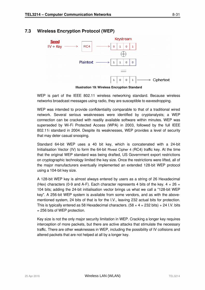
Illustration 19: Wireless Encryption Standard
WEP is part of the IEEE 802.11 wireless networking standard. Because wirelessnetworks broadcast messages using radio, they are susceptible to eavesdropping.
WEP was intended to provide confidentiality comparable to that of a traditional wirednetwork. Several serious weaknesses were identified by cryptanalysts; a WEPconnection can be cracked with readily available software within minutes. WEP wassuperseded by Wi-Fi Protected Access (WPA) in 2003, followed by the full IEEE802.11i standard in 2004. Despite its weaknesses, WEP provides a level of securitythat may deter casual snooping.
Standard 64-bit WEP uses a 40 bit key, which is concatenated with a 24-bitInitialisation Vector (IV) to form the 64-bit Rivest Cipher 4 (RC4) traffic key. At the timethat the original WEP standard was being drafted, US Government export restrictionson cryptographic technology limited the key size. Once the restrictions were lifted, all ofthe major manufacturers eventually implemented an extended 128-bit WEP protocolusing a 104-bit key size.
A 128-bit WEP key is almost always entered by users as a string of 26 Hexadecimal(Hex) characters (0-9 and A-F). Each character represents 4 bits of the key. 4 × 26 =104 bits; adding the 24-bit initialisation vector brings us what we call a "128-bit WEPkey". A 256-bit WEP system is available from some vendors, and as with the above-mentioned system, 24 bits of that is for the I.V., leaving 232 actual bits for protection.This is typically entered as 58 Hexadecimal characters. (58 × 4 = 232 bits) + 24 I.V. bits= 256 bits of WEP protection.
Key size is not the only major security limitation in WEP. Cracking a longer key requiresinterception of more packets, but there are active attacks that stimulate the necessarytraffic. There are other weaknesses in WEP, including the possibility of IV collisions andaltered packets that are not helped at all by a longer key.
25 Apr 2016 Wireless LAN (WLAN) TEL3214
8-32 TEL3214 – Computer Communication Networks
7.4 Wi-Fi Protected Access (WPA)WPA is a class of systems to secure wireless (Wi-Fi) computer networks. It wascreated in response to several serious weaknesses researchers had found in theprevious system, WEP. WPA implements the majority of the IEEE 802.11i standard,and was intended as an intermediate measure to take the place of WEP while 802.11iwas prepared. WPA is designed to work with all wireless network interface cards, butnot necessarily with first generation wireless access points. WPA2 (also called 802.11i)implements the full standard, but will not work with some older network cards. Bothprovide good security, with two significant issues:
Either WPA or WPA2 must be enabled and chosen in preference to WEP. WEP isusually presented as the first security choice in most installation instructions.
In the "Personal" mode, the most likely choice for homes and small offices, apassphrase is required that, for full security, must be longer than the typical 6 to 8character passwords users are taught to employ.
WPA resolves the issue of weak WEP headers, which are called initialisation vectors(IV), and insures the integrity of the messages passed through (Message IntegrityCheck (MIC) using Temporal Key Integrity Protocol (TKIP) to enhance data encryption.
WPA-PSK is a special mode of WPA for home users without an enterpriseauthentication server and provides the same strong encryption protection.
7.4.1 Security in pre-shared key mode
Pre Shared Key (PSK) mode is designed for home and small office networks thatcannot afford the cost and complexity of an 802.1X authentication server. Each usermust enter a passphrase to access the network. The passphrase may be from 8 to 63printable American Standard Code for Information Interchange (ASCII) characters or64 hexadecimal digits (256 bits). If you choose to use the ASCII characters, a hashfunction reduces it from 504 bits (63 characters * 8 bits/character) to 256 bits (usingalso the SSID). The passphrase may be stored on the user's computer at theirdiscretion under most operating systems to avoid re-entry. The passphrase mustremain stored in the Wi-Fi access point.
Security is strengthened by employing a Password-Based Key Derivation Functionversion 2 (PBKDF2). However, the weak passphrases users typically employ arevulnerable to password cracking attacks.
Some consumer chip manufacturers have attempted to bypass weak passphrasechoice by adding a method of automatically generating and distributing strong keysthrough a software or hardware interface that uses an external method of adding a newWi-Fi adapter or appliance to a network.
TEL3214 Wireless LAN (WLAN) 25 Apr 2016
TEL3214 – Computer Communication Networks 8-33
7.4.2 Security with an Authentication Server
With WPA the use of 802.1x is supported for operation with databases of users storedin Remote Access Dialin User Service (RADIUS) and this is accessed using ExtensibleAuthentication Protocol (EAP).
7.4.3 IEEE 802.1X
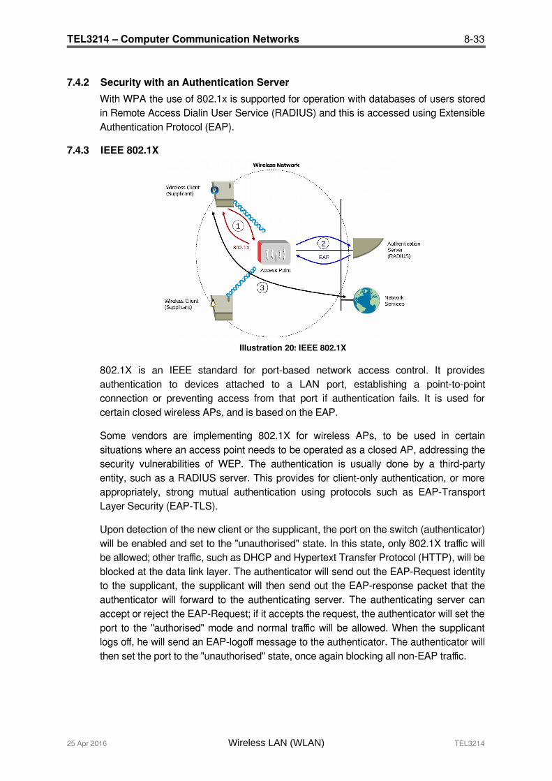
Illustration 20: IEEE 802.1X
802.1X is an IEEE standard for port-based network access control. It providesauthentication to devices attached to a LAN port, establishing a point-to-pointconnection or preventing access from that port if authentication fails. It is used forcertain closed wireless APs, and is based on the EAP.
Some vendors are implementing 802.1X for wireless APs, to be used in certainsituations where an access point needs to be operated as a closed AP, addressing thesecurity vulnerabilities of WEP. The authentication is usually done by a third-partyentity, such as a RADIUS server. This provides for client-only authentication, or moreappropriately, strong mutual authentication using protocols such as EAP-TransportLayer Security (EAP-TLS).
Upon detection of the new client or the supplicant, the port on the switch (authenticator)will be enabled and set to the "unauthorised" state. In this state, only 802.1X traffic willbe allowed; other traffic, such as DHCP and Hypertext Transfer Protocol (HTTP), will beblocked at the data link layer. The authenticator will send out the EAP-Request identityto the supplicant, the supplicant will then send out the EAP-response packet that theauthenticator will forward to the authenticating server. The authenticating server canaccept or reject the EAP-Request; if it accepts the request, the authenticator will set theport to the "authorised" mode and normal traffic will be allowed. When the supplicantlogs off, he will send an EAP-logoff message to the authenticator. The authenticator willthen set the port to the "unauthorised" state, once again blocking all non-EAP traffic.
25 Apr 2016 Wireless LAN (WLAN) TEL3214
8-34 TEL3214 – Computer Communication Networks
7.5 802.11i WPA2 The Wi-Fi Alliance approved full 802.11i as WPA2, also called Robust SecurityNetwork (RSN). WPA2 implements the mandatory elements of 802.11i. It introducesAdvanced Encryption Standard (AES) algorithm based algorithm, Counter Mode withCipher Block Chaining Message Authentication Code Protocol (CCMP) that isconsidered fully secure.
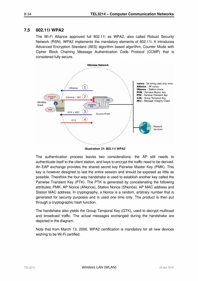
Illustration 21: 802.11i WPA2
The authentication process leaves two considerations: the AP still needs toauthenticate itself to the client station, and keys to encrypt the traffic need to be derived.An EAP exchange provides the shared secret key Pairwise Master Key (PMK). Thiskey is however designed to last the entire session and should be exposed as little aspossible. Therefore the four-way handshake is used to establish another key called thePairwise Transient Key (PTK). The PTK is generated by concatenating the followingattributes: PMK, AP Nonce (ANonce), Station Nonce (SNonce), AP MAC address andStation MAC address. In cryptography, a Nonce is a random, arbitrary number that isgenerated for security purposes and is used one time only. The product is then putthrough a cryptographic hash function.
The handshake also yields the Group Temporal Key (GTK), used to decrypt multicastand broadcast traffic. The actual messages exchanged during the handshake aredepicted in the diagram.
Note that from March 13, 2006, WPA2 certification is mandatory for all new deviceswishing to be Wi-Fi certified.
TEL3214 Wireless LAN (WLAN) 25 Apr 2016
TEL3214 – Computer Communication Networks 8-35
8. Non Wi-Fi Solutions in Unlicensed Spectrum
A number of manufacturers have developed solutions for unlicensed spectrum toprovide both PTP and Point to Multi Point (PTMP) connectivity. Such systems aretargeted at WISPs who typically started out as a small local broadband schemeplugging a hole in the area where broadband was not being supplied by the traditionalcarriers. As WISPs expand their channel capacity with growth, interference becomesan issue. The proprietary solutions generally claim to suffer less from interference thatstandard WLAN. Motorola Canopy and Alvarion BreezeACCESS are examples.MikroTik and Ubiquiti offer 802.11 based solutions with proprietary enhancements in anattempt to achieve the same outcome. Both of these companies are now also offeringTDMA based solutions to overcome the problems 802.11 has in the outdoors.
8.1 MikroTik - Nstreme / Nv2MikroTik implement a software router operating system called RouterOS which can runon i386 based hardware. They also have a hardware arm called RouterBOARD whodevelop hardware for specific needs like P2P and PTMP for the RouterOS. MikroTikwireless devices are based on 802.11 protocols with the addition of some proprietaryadditions.
8.2 NstremeNstreme and Nstreme2 are MikroTik proprietary wireless protocols developed byMikroTik for use with Atheros wireless chips to achieve higher performance on a verylong range links. Regular 802.11 wireless links will have large time delays for datatravelling over long distances, nstreme overcomes this problem.
8.3 Nstreme 2Nstreme 2 gives further range by using two Atheros based wireless cards in each end -one for transmit and one for receive.
8.4 Nv2 (Nstreme version 2)Nv2 protocol is proprietary wireless protocol developed by MikroTik for use withAtheros 802.11 wireless chips. Nv2 is based on Time Division Multiple Access (TDMA)media access technology instead of using CSMA as used in IEEE 802.11.
25 Apr 2016 Wireless LAN (WLAN) TEL3214
8-36 TEL3214 – Computer Communication Networks
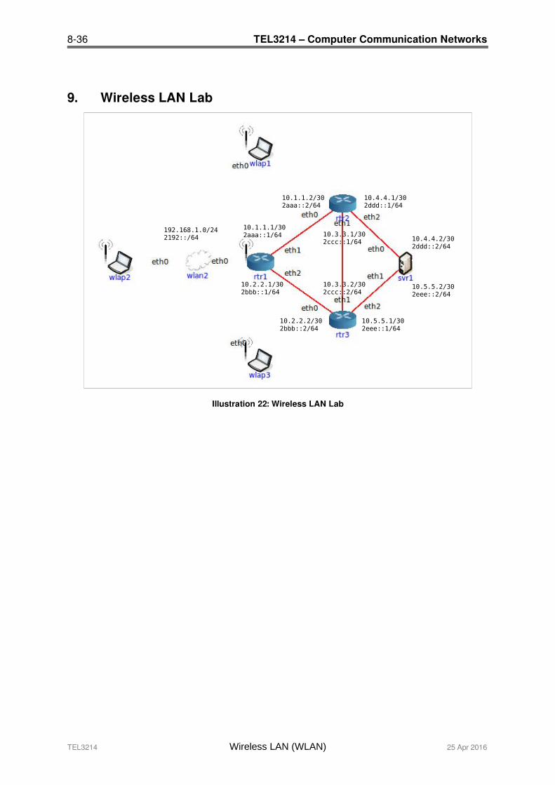
9. Wireless LAN Lab
TEL3214 Wireless LAN (WLAN) 25 Apr 2016
Illustration 22: Wireless LAN Lab
10.4.4.2/302ddd::2/64
10.5.5.2/302eee::2/64
10.4.4.1/302ddd::1/64
10.5.5.1/302eee::1/64
10.1.1.2/302aaa::2/64
10.2.2.2/302bbb::2/64
10.1.1.1/302aaa::1/64
10.2.2.1/302bbb::1/64
10.3.3.1/302ccc::1/64
10.3.3.2/302ccc::2/64
192.168.1.0/242192::/64
TEL3214 – Computer Communication Networks 8-37
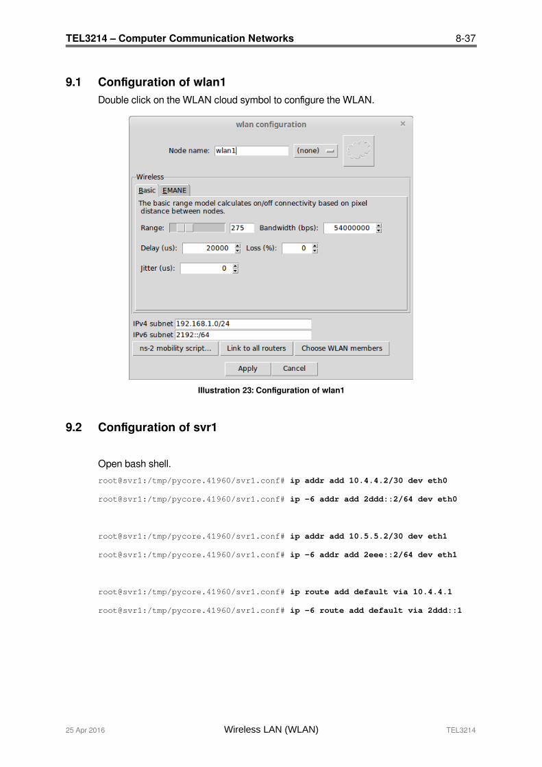
9.1 Configuration of wlan1Double click on the WLAN cloud symbol to configure the WLAN.
9.2 Configuration of svr1
Open bash shell.
root@svr1:/tmp/pycore.41960/svr1.conf# ip addr add 10.4.4.2/30 dev eth0
root@svr1:/tmp/pycore.41960/svr1.conf# ip -6 addr add 2ddd::2/64 dev eth0
root@svr1:/tmp/pycore.41960/svr1.conf# ip addr add 10.5.5.2/30 dev eth1
root@svr1:/tmp/pycore.41960/svr1.conf# ip -6 addr add 2eee::2/64 dev eth1
root@svr1:/tmp/pycore.41960/svr1.conf# ip route add default via 10.4.4.1
root@svr1:/tmp/pycore.41960/svr1.conf# ip -6 route add default via 2ddd::1
25 Apr 2016 Wireless LAN (WLAN) TEL3214
Illustration 23: Configuration of wlan1

8-38 TEL3214 – Computer Communication Networks
9.3 Configuration of rtr1Configuration of Router rtr1 DHCP Service.
subnet 192.168.1.0 netmask 255.255.255.0 { pool { range 192.168.1.2 192.168.1.254; default-lease-time 600; option routers 192.168.1.1; option domain-name-servers 8.8.8.8; }}
Configuration of Router rtr1 via the vtysh shell. rtr1# conf t
rtr1(config)# int eth0
rtr1(config-if)# ip addr 192.168.1.1/24
rtr1(config-if)# ipv6 addr 2192::1/64
rtr1(config-if)# ipv6 nd prefix 2192::/64 86400 86400
rtr1(config-if)# ipv6 nd reachable-time 5000
rtr1(config-if)# no ipv6 nd suppress-ra
rtr1(config-if)# ipv6 ospf6 network broadcast
rtr1(config-if)# ipv6 ospf6 passive
rtr1(config-if)# no shut
rtr1(config-if)# int eth1
rtr1(config-if)# ip addr 10.1.1.1/30
rtr1(config-if)# ipv6 addr 2aaa::1/64
rtr1(config-if)# ipv6 nd suppress-ra
rtr1(config-if)# ipv6 ospf6 network point-to-point
rtr1(config-if)# no shut
rtr1(config-if)# int eth2
rtr1(config-if)# ip addr 10.2.2.1/30
rtr1(config-if)# ipv6 addr 2bbb::1/64
rtr1(config-if)# ipv6 nd suppress-ra
rtr1(config-if)# ipv6 ospf6 network point-to-point
rtr1(config-if)# no shut
rtr1(config-if)# int lo
rtr1(config-if)# ip addr 10.0.0.1/32
rtr1(config-if)# ipv6 addr 2001::1/128
rtr1(config-if)# no shut
rtr1(config-if)# router ospf
rtr1(config-router)# router-id 10.0.0.1
rtr1(config-router)# network 192.168.1.0/24 area 0.0.0.0
rtr1(config-router)# network 10.0.0.0/8 area 0.0.0.0
rtr1(config-router)# router ospf6
rtr1(config-router)# router-id 10.0.0.1
rtr1(config-router)# interface eth0 area 0.0.0.0
rtr1(config-router)# interface eth1 area 0.0.0.0
rtr1(config-router)# interface eth2 area 0.0.0.0
rtr1(config-router)# interface lo area 0.0.0.0
TEL3214 Wireless LAN (WLAN) 25 Apr 2016

TEL3214 – Computer Communication Networks 8-39
9.4 Configuration of rtr2rtr2# conf t
rtr2(config)# int eth0
rtr2(config-if)# ip addr 10.1.1.2/30
rtr2(config-if)# ipv6 addr 2aaa::2/64
rtr2(config-if)# ipv6 nd suppress-ra
rtr2(config-if)# ipv6 ospf6 network point-to-point
rtr2(config-if)# no shut
rtr2(config-if)# int eth1
rtr2(config-if)# ip addr 10.3.3.1/30
rtr2(config-if)# ipv6 addr 2ccc::1/64
rtr2(config-if)# ipv6 nd suppress-ra
rtr2(config-if)# ipv6 ospf6 network point-to-point
rtr2(config-if)# no shut
rtr2(config-if)# int eth2
rtr2(config-if)# ip addr 10.4.4.1/30
rtr2(config-if)# ipv6 addr 2ddd::1/64
rtr2(config-if)# ipv6 nd suppress-ra
rtr2(config-if)# ipv6 ospf6 network point-to-point
rtr2(config-if)# no shut
rtr2(config-if)# int lo
rtr2(config-if)# ip addr 10.0.0.2/32
rtr2(config-if)# ipv6 addr 2001::2/128
rtr2(config-if)# no shut
rtr2(config-if)# router ospf
rtr2(config-router)# router-id 10.0.0.2
rtr2(config-router)# network 10.0.0.0/8 area 0.0.0.0
rtr2(config-router)# router ospf6
rtr2(config-router)# router-id 10.0.0.2
rtr2(config-router)# interface eth0 area 0.0.0.0
rtr2(config-router)# interface eth1 area 0.0.0.0
rtr2(config-router)# interface eth2 area 0.0.0.0
rtr2(config-router)# interface lo area 0.0.0.0
25 Apr 2016 Wireless LAN (WLAN) TEL3214
8-40 TEL3214 – Computer Communication Networks
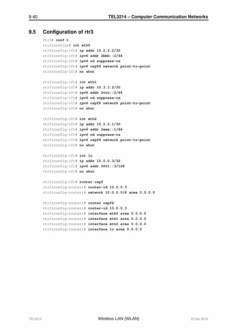
9.5 Configuration of rtr3rtr3# conf t
rtr3(config)# int eth0
rtr3(config-if)# ip addr 10.2.2.2/30
rtr3(config-if)# ipv6 addr 2bbb::2/64
rtr3(config-if)# ipv6 nd suppress-ra
rtr3(config-if)# ipv6 ospf6 network point-to-point
rtr3(config-if)# no shut
rtr3(config-if)# int eth1
rtr3(config-if)# ip addr 10.3.3.2/30
rtr3(config-if)# ipv6 addr 2ccc::2/64
rtr3(config-if)# ipv6 nd suppress-ra
rtr3(config-if)# ipv6 ospf6 network point-to-point
rtr3(config-if)# no shut
rtr3(config-if)# int eth2
rtr3(config-if)# ip addr 10.5.5.1/30
rtr3(config-if)# ipv6 addr 2eee::1/64
rtr3(config-if)# ipv6 nd suppress-ra
rtr3(config-if)# ipv6 ospf6 network point-to-point
rtr3(config-if)# no shut
rtr3(config-if)# int lo
rtr3(config-if)# ip addr 10.0.0.3/32
rtr3(config-if)# ipv6 addr 2001::3/128
rtr3(config-if)# no shut
rtr3(config-if)# router ospf
rtr3(config-router)# router-id 10.0.0.3
rtr3(config-router)# network 10.0.0.0/8 area 0.0.0.0
rtr3(config-router)# router ospf6
rtr3(config-router)# router-id 10.0.0.3
rtr3(config-router)# interface eth0 area 0.0.0.0
rtr3(config-router)# interface eth1 area 0.0.0.0
rtr3(config-router)# interface eth2 area 0.0.0.0
rtr3(config-router)# interface lo area 0.0.0.0
TEL3214 Wireless LAN (WLAN) 25 Apr 2016
TEL3214 – Computer Communication Networks 8-41
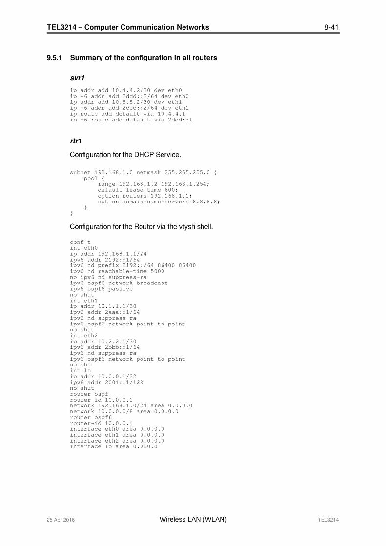
9.5.1 Summary of the configuration in all routers
svr1
ip addr add 10.4.4.2/30 dev eth0ip -6 addr add 2ddd::2/64 dev eth0ip addr add 10.5.5.2/30 dev eth1ip -6 addr add 2eee::2/64 dev eth1ip route add default via 10.4.4.1ip -6 route add default via 2ddd::1
rtr1
Configuration for the DHCP Service.
subnet 192.168.1.0 netmask 255.255.255.0 { pool { range 192.168.1.2 192.168.1.254; default-lease-time 600; option routers 192.168.1.1; option domain-name-servers 8.8.8.8; }}
Configuration for the Router via the vtysh shell.
conf tint eth0ip addr 192.168.1.1/24ipv6 addr 2192::1/64ipv6 nd prefix 2192::/64 86400 86400ipv6 nd reachable-time 5000no ipv6 nd suppress-raipv6 ospf6 network broadcastipv6 ospf6 passiveno shutint eth1ip addr 10.1.1.1/30ipv6 addr 2aaa::1/64ipv6 nd suppress-raipv6 ospf6 network point-to-pointno shutint eth2ip addr 10.2.2.1/30ipv6 addr 2bbb::1/64ipv6 nd suppress-raipv6 ospf6 network point-to-pointno shutint loip addr 10.0.0.1/32ipv6 addr 2001::1/128no shutrouter ospfrouter-id 10.0.0.1network 192.168.1.0/24 area 0.0.0.0network 10.0.0.0/8 area 0.0.0.0router ospf6router-id 10.0.0.1interface eth0 area 0.0.0.0interface eth1 area 0.0.0.0interface eth2 area 0.0.0.0interface lo area 0.0.0.0
25 Apr 2016 Wireless LAN (WLAN) TEL3214
8-42 TEL3214 – Computer Communication Networks
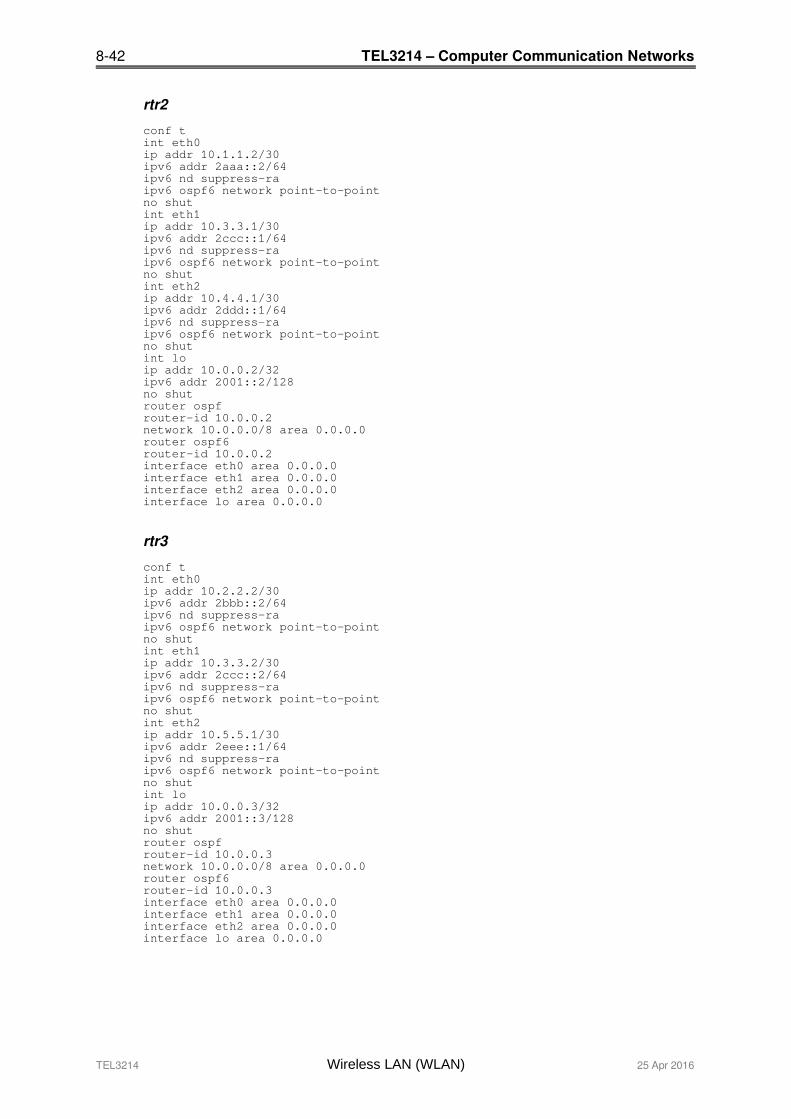
rtr2
conf tint eth0ip addr 10.1.1.2/30ipv6 addr 2aaa::2/64ipv6 nd suppress-raipv6 ospf6 network point-to-pointno shutint eth1ip addr 10.3.3.1/30ipv6 addr 2ccc::1/64ipv6 nd suppress-raipv6 ospf6 network point-to-pointno shutint eth2ip addr 10.4.4.1/30ipv6 addr 2ddd::1/64ipv6 nd suppress-raipv6 ospf6 network point-to-pointno shutint loip addr 10.0.0.2/32ipv6 addr 2001::2/128no shutrouter ospfrouter-id 10.0.0.2network 10.0.0.0/8 area 0.0.0.0router ospf6router-id 10.0.0.2interface eth0 area 0.0.0.0interface eth1 area 0.0.0.0interface eth2 area 0.0.0.0interface lo area 0.0.0.0
rtr3
conf tint eth0ip addr 10.2.2.2/30ipv6 addr 2bbb::2/64ipv6 nd suppress-raipv6 ospf6 network point-to-pointno shutint eth1ip addr 10.3.3.2/30ipv6 addr 2ccc::2/64ipv6 nd suppress-raipv6 ospf6 network point-to-pointno shutint eth2ip addr 10.5.5.1/30ipv6 addr 2eee::1/64ipv6 nd suppress-raipv6 ospf6 network point-to-pointno shutint loip addr 10.0.0.3/32ipv6 addr 2001::3/128no shutrouter ospfrouter-id 10.0.0.3network 10.0.0.0/8 area 0.0.0.0router ospf6router-id 10.0.0.3interface eth0 area 0.0.0.0interface eth1 area 0.0.0.0interface eth2 area 0.0.0.0interface lo area 0.0.0.0
TEL3214 Wireless LAN (WLAN) 25 Apr 2016
TEL3214 – Computer Communication Networks 8-43
10. Self-test Quiz
1. List the IEEE standards that use the 5 GHz Short Range Devices band.
2. Define the difference between:
• Independent Basic Service Set
• Basic Service Set
3. What are the key differences between WEP and WPA2?
25 Apr 2016 Wireless LAN (WLAN) TEL3214
8-44 TEL3214 – Computer Communication Networks
This page is intentionally blank
TEL3214 Wireless LAN (WLAN) 25 Apr 2016