BS 8313-1997 Code of Practice for Accommodation of Building Services in Ducts
54
| | | | | | | | | | | | | | | | | | | | | | | | | | | | | | | | | | | | | | | | | | | | | | | | | | | | | | | | | | | | | | | | | | | | | | | | | | | | | | | | | | | | | | | | | | | | | | | | | | | | | | | | | | | | | | | | | | | | | | | | | | | | | | | | | BRITISH STANDARD BS 8313 : 1997 ICS 91.140.01 NO COPYING WITHOUT BSI PERMISSION EXCEPT AS PERMITTED BY COPYRIGHT LAW Code of practice for Accommodation of building services in ducts Licensed copy:PONTYPRIDD COLLEGE, 15/02/2008, Uncontrolled Copy, © BSI
-
Upload
fathykholief -
Category
Documents
-
view
325 -
download
17
description
coordination
Transcript of BS 8313-1997 Code of Practice for Accommodation of Building Services in Ducts

|||||||||||||||||||||||||||||||||||||||||||||||||||||||||||||||||||||||||||||||||||||||||||||||||||||||||||||||||||||||||||||||||
BRITISH STANDARD BS 8313 : 1997
ICS 91.140.01
NO COPYING WITHOUT BSI PERMISSION EXCEPT AS PERMITTED BY COPYRIGHT LAW
Code of practice for
Accommodation ofbuilding services inducts
Licensed copy:PONTYPRIDD COLLEGE, 15/02/2008, Uncontrolled Copy, © BSI

BS 8313 : 1997
This British Standard, havingbeen prepared under thedirection of the Sector Board forBuilding and Civil Engineering,was published under theauthority of the Standards Boardand comes into effect on15 July 1997
BSI 1997
First published as CP 413,March 1951Second edition July 1973Third edition July 1989Fourth edition July 1997
The following BSI referencesrelate to the work on thisstandard:Committee reference B/209/14Draft for comment 96/103803 DC
ISBN 0 580 27363 6
Amendments issued since publication
Amd. No. Date Text affected
Committees responsible for thisBritish Standard
The preparation of this British Standard was entrusted to Technical CommitteeB/209/14, Building services, upon which the following bodies were represented:
Combustion Engineering Association
Institute of Plumbing
British Gas plc
Chartered Institution of Building Services Engineers
Clay Pipe Development Association Limited
Licensed copy:PONTYPRIDD COLLEGE, 15/02/2008, Uncontrolled Copy, © BSI

www.bzfxw.com
BS 8313 : 1997
BSI 1997 i
Contents
Page
Committees responsible Inside front cover
Foreword iii
Code of practice 1
1 Scope 1
2 References 1
3 Definitions 1
4 Exchange of information 2
5 Materials and components 2
6 General 2
7 Restrictions on positioning and combination of services 3
8 Space requirements 6
9 Access 7
10 Protection of services in ducts 10
11 Drainage of service ducts 10
12 Ventilation of service ducts 10
13 Fire precautions 12
14 Other safety precautions 14
15 Service entries and exits 15
16 Identification and marking 16
17 Duct construction 16
18 Inspection and testing 17
19 Maintenance 17
Annexes
A (informative) Installation space for air ducts (detailed method) 18
B (informative) Installation space for air ducts (simplified method) 39
C (informative) Work in confined spaces 42
D (informative) Acts, bylaws and statutory regulations 42
Tables
1 Free area of ventilation opening for dispersal of small leaks 11
A.1 Dimensions where f1 = 100 and f2 = 300 27
A.2 Dimensions where f1 = 100 and f2 = 300 28
A.3 Dimensions where f1 = 100 and f2 = 300 29
A.4 Dimensions where f1 = 100 and f2 = 300 30
A.5 Values of ea and eb 31
A.6 Values of ea1, ea2, eb1 and eb2 31
A.7 Values of ea1, ea2, eb1 and eb2 by firm obstacles 33
A.8 Values of n for a firm obstacle on one side 36
A.9 Values of n for a firm obstacle on two sides 37
A.10 Values of n for a firm obstacle on three sides 37
A.11 Values of n for a firm obstacle on four sides 38
B.1 Dimensions of X 41
Licensed copy:PONTYPRIDD COLLEGE, 15/02/2008, Uncontrolled Copy, © BSI

www.bzfxw.com
BS 8313 : 1997
ii BSI 1997
Figures
1 Minimum sizes of access openings for passage by persons 7
2 Anthropometric data 8
A.1 Space with limitations due to firm obstacles 20
A.2 Jointing and supporting air ducts without insulation and with a firmobstacle on one side 20
A.3 Jointing and supporting air ducts without insulation and with a firmobstacle on two sides 21
A.4 Jointing and supporting air ducts without insulation and with a firmobstacle on three sides 21
A.5 Jointing and supporting air ducts without insulation and with a firmobstacle on four sides (obstacle not continuous for more than 1 m) 22
A.6 Jointing and supporting pre-insulated air ducts with a firm obstacle on oneside 22
A.7 Jointing and supporting pre-insulated air ducts with a firm obstacle on twosides 23
A.8 Jointing and supporting pre-insulated air ducts with a firm obstacle onthree sides 23
A.9 Jointing and supporting pre-insulated air ducts with a firm obstacle onfour sides (obstacle not continuous for more than 1 m) 24
A.10 Insulation of an air duct in position with a firm obstacle on one side 24
A.11 Insulation of an air duct in position with a firm obstacle on two sides 25
A.12 Insulation of an air duct in position with a firm obstacle on three sides 25
A.13 Insulation of an air duct in position with a firm obstacle on four sides(obstacle not continuous for more than 1 m) 26
A.14 Examples of installation spaces for flange jointed air ducts 26
A.15 Installation space dimensions A and B for flange jointed air ducts with afirm obstacle on one side 27
A.16 Installation space dimensions A and B for flange jointed air ducts with afirm obstacle on two sides 28
A.17 Installation space dimensions A and B for flange jointed air ducts with afirm obstacle on three sides 29
A.18 Installation space dimensions A and B for flange jointed air ducts with afirm obstacle on four sides 30
A.19 Examples of installation space for slip jointed air ducts 31
A.20 Installation space dimensions A and B for slip jointed air ducts with a firmobstacle on one or more sides 32
A.21 e-values 33
A.22 Minimum access allowance e for air ducts insulated in position 34
A.23 Installation space dimensions A and B for air ducts insulated in positionwith a firm obstacle on one side 34
A.24 Installation space dimensions A and B for air ducts insulated in positionwith a firm obstacle on two sides 35
A.25 Installation space dimensions A and B for air ducts insulated in positionwith a firm obstacle on three sides 35
A.26 Installation space dimensions A and B for air ducts insulated in positionwith a firm obstacle on four sides 36
B.1 Installation spaces for uninsulated or pre-insulated air ducts 40
B.2 Installation spaces for air ducts insulated after installation 41
Index 44
List of references 47
Licensed copy:PONTYPRIDD COLLEGE, 15/02/2008, Uncontrolled Copy, © BSI
www.bzfxw.com
BSI 1997 iii
BS 8313 : 1997
Foreword
This British Standard has been prepared under the direction of the TechnicalCommittee B/209. It supersedes BS 8313 : 1989, which is withdrawn.
This edition introduces technical changes but it does not reflect a full review orrevision of the document, which will be undertaken in due course.
This code of practice is intended to provide architects, engineers, builders, contractors,suppliers, specialists, and service engineers with recommendations for the design,construction, installation and maintenance of ducts in buildings for theaccommodation of services. It also covers ducts attached to the outside of buildings,suspended flooring and ceiling voids, and cavities which are used for services but notalways referred to as ducts. Annex A gives a detailed method for calculating theminimum cross-sectional dimensions of space required in service ducts for theinstallation and maintenance of thin walled HVAC ducting and annex B provides asimplified method for doing the same calculation. Annex C draws attention to thestressful nature and potential hazards associated with working in a confined space andannex D lists Acts, bylaws and statutory regulations which relate to theaccommodation and maintenance of building services in ducts.
As a code of practice, this British Standard takes the form of guidance andrecommendations. It should not be quoted as if it were a specification and care shouldbe taken to ensure that claims of compliance are not misleading. In particular,attention is drawn to 6.1 and the fact that statutory legislation may impose morestringent requirements in certain circumstances.
The standard should not be regarded as a substitute for expert advice. The intention isthat it should complement it.
Every fire authority has Fire Prevention Officers who will advise designers, owners andoccupiers and who will welcome liaison with architects and facilities engineers on thesafety aspects of building design. Advice can also be obtained from the Health andSafety Executive and from local authorities on matters relating to health and safety,and from Building Control Officers if new buildings or major alterations are involved.
Compliance with a British Standard does not of itself confer immunityfrom legal obligations.
Summary of pages
This document comprises a front cover, an inside front cover, pages i to iv, pages 1 to48, an inside back cover and a back cover.
Licensed copy:PONTYPRIDD COLLEGE, 15/02/2008, Uncontrolled Copy, © BSI

www.bzfxw.com
iv blankLicensed copy:PONTYPRIDD COLLEGE, 15/02/2008, Uncontrolled Copy, © BSI

www.bzfxw.com
BSI 1997 1
BS 8313 : 1997
Code of practice
1 ScopeThis British Standard gives recommendations for thedesign, construction, installation and maintenance ofducts in buildings used for the accommodation ofservices. It also covers enclosures such as ceilingvoids and cavities which are used for services butwhich are not always referred to as ducts.
The recommendations in this standard should alsobe applied as far as practicable to the adaptation,modification or refurbishment of existing ducts andservices within them. Appropriate precautions shouldbe taken in all cases where the existing ductscontain hazardous materials, e.g. asbestos.
This standard covers service ducts attached to theoutside of buildings but not service ducts betweenbuildings.
This standard does not cover the design andconstruction of air or refuse ducts, nor those with`heart units', `packaged plumbing' or `service walls',although parts of it are relevant to them.
This standard does not cover spaces intended mainlyfor purposes other than the accommodation ofservices, nor with plant areas such as boiler andcalorifier rooms or gas storage areas.
The piping of radioactive substances and thespecialist requirements for piping cryogenic liquidsare generally outside the scope of this standard.
2 References
2.1 Normative references
This standard incorporates, by dated or undatedreference, provisions from other publications. Thesenormative references are made at the appropriateplaces in the text and the cited publications arelisted on page 47. For dated references, only theedition cited applies; any subsequent amendments toor revisions of the cited publication apply to thisstandard only when incorporated in the reference byamendment or revision. For undated references, thelatest edition of the cited publication applies,together with any amendments.
2.2 Informative references
This standard refers to other publications thatprovide information or guidance. Editions of thesepublications current at the time of issue of thisstandard are listed on page 48, but reference shouldbe made to the latest editions.
3 DefinitionsFor the purposes of this British Standard thedefinitions given in BS 6100 apply, together with thefollowing.
3.1 duct
Space formed for the passage of cables, pipes, etc.
3.2 service duct
Duct that allows working space.
3.3 pipe sleeve
Protective pipe through which a carrier pipe or cableis later passed.
3.4 cavity barrier
Construction provided to seal a cavity against thepenetration of smoke and flame, or within a cavity torestrict the movement of smoke and flame within thecavity.
3.5 fire compartmentation
Division of a building into compartments byelements of building construction intended to resistthe passage of fire, and capable of meeting specifiedperformance criteria to those ends.
3.6 fire door
Door or shutter provided for the passage of persons,air or objects which, together with its frame andfurniture as installed in a building, is intended whenclosed to resist the passage of fire and/or gaseousproducts of combustion and is capable of meetingspecified performance criteria to those ends.
3.7 fire resistance
Ability of a component or construction of a buildingto satisfy for a stated period of time some or all ofthe criteria specified in BS 476 : Part 4 and BS 476 :Part 24, covering stability, integrity and insulation.
3.8 fire stop
Seal provided to close an imperfection of fit betweenelements, components or construction in a building,or in any joint, so as to restrict penetration of smokeand flame through that imperfection or joint.
3.9 firm obstacle
Any obstacle that will interfere with the installation,dismantling or maintenance of a service.
3.10 flash point
Lowest temperature at which vapour from oil, etc.can be ignited by an external source.
3.11 installation space
Recommended minimum space necessary for theinstallation and maintenance of one or more serviceswhere access is limited by a firm obstacle. It isexpressed as a rectangular envelope at right anglesto and at any point along a run of services. Itincludes allowances for supports, thermal and soundinsulation, and safety margins.
3.12 material of limited combustibility
Material that conforms to any of the specificationsgiven for materials of limited combustibility in theApproved Document published in connection withB2/B3/B4 of the Building Regulations 1991[1].
3.13 nominal size
Size used in the designation of appliance orcomponent.
3.14 protected shaft
Stairway, lift, escalator, chute, duct, or other shaftwhich enables persons, objects or air to pass fromone compartment to another.
Licensed copy:PONTYPRIDD COLLEGE, 15/02/2008, Uncontrolled Copy, © BSI

www.bzfxw.com
2 BSI 1997
BS 8313 : 1997
3.15 protected stairway
Stairway, including any exit passageway leadingtherefrom to its final exit, enclosed with (other thanany part that is an external wall of a building)fire-resisting construction.
3.16 budget lock
Lock that has a pivoted tongue, that, whenturned 90Ê by a key, swings into a slot striking plateto serve as a deadbolt.
4 Exchange of information
4.1 Responsibility for design
Before work is begun, a person should be appointedto be responsible for design of the service ducts andco-ordination of the services within them.
4.2 Consultation and co-ordination
The necessary consultation and co-ordination shouldbe carried out and particular attention should bepaid to the following points:
a) brief from client;
b) system for ensuring that drawings andspecifications reach those who need them;
c) system for spatial co-ordination;
d) project programme;
e) consultation with planning, building regulationsand fire authorities;
f) consultation with gas, electricity, water,sewerage and telecommunications authorities;
g) consultation with insurers;
h) consultation with suppliers of special servicessuch as industrial and medical gases (or otherauthoritative source);
i) operation and maintenance instructions;
j) the possibility of increased future requirementsowing to further development within or adjacentto the project should be considered.
NOTE. Lack of systematic advance planning of services can resultin delays and expensive alterations.
5 Materials and components
5.1 British Standards
Materials and components should conform torelevant British Standards.
5.2 Choice of materials and components
Factors that should be considered when ductmaterials and components are selected are asfollows, not necessarily in order of importance.
a) Mechanical properties: strength, elasticity,ductility and mass.
b) Electrical properties: electrical conductivity andelectrical insulating strength (of an insulator).
NOTE. Insulating materials may create the risk of electrostaticdischarges.
c) Chemical properties: corrosion, dissolution orother failure that may result from reaction withother constituents of the duct or services(e.g. galvanic corrosion of mixed metals), escapeof gases or liquids within the duct, or the action ofwater vapour, steam or other vapours in the air.
d) Thermal properties: thermal conductivity,thermal expansion and stability.
e) Acoustic properties: acoustic absorption andinsulation.
f) Health hazards. The material or component onceinstalled should not be hazardous to persons or tothe environment. Materials that are poisonous orproduce harmful gases or dusts before or duringinstallation should be closely controlled. Attentionis drawn to the controls in relation to asbestosimposed by the Health and Safety at Work etc.Act 1974 [2], the Asbestos (Licensing)Regulations 1983 [3] and the Asbestos (Prohibition)Regulations 1992 [4] and the Control of Asbestos atWork Regulations 1987 [5]. Guidance on workinvolving exposure or potential exposure toasbestos is found in the Health and SafetyExecutive (HSE) publications EH10 [6], L27 [7] andL28 [8]. Components should be free of sharp edgesand projecting spikes, and should be easy toassemble.
g) Resistance to fire: combustibility, fire resistanceand resistance to fire spread of the completed ductand its contents should always be assessed as partof the overall fire engineering design of thebuilding.
h) Resistance to pests: materials should not beliable to attack by insects, fungi or vermin orshould be protected by suitable preservatives.
i) Cost and availability: cost and availability affectboth construction and maintenance.
j) Ease of installation and maintenance. Materialsand components should be chosen taking intoconsideration the labour, tools and equipmentlikely to be available for installation andmaintenance, including cleaning. If installation andmaintenance is easy, it is more likely to be doneproperly.
6 General
6.1 Statutory provisions
It is essential that designers of buildings, serviceinstallations and ducts are aware that there is a widerange of Acts, Regulations and Bylaws covering suchwork in England and Wales, Scotland and NorthernIreland (see annex D). It is their duty to ensurecompliance with the relevant requirements.
6.2 Principles of general arrangement
Most projects require that services be enclosed forpart of their route through the building or buildings.Services may be enclosed in a variety of types ofspace.
Licensed copy:PONTYPRIDD COLLEGE, 15/02/2008, Uncontrolled Copy, © BSI

www.bzfxw.com
BSI 1997 3
BS 8313 : 1997
Service ducts may be formed as part of the buildingstructure or as non load bearing elements.
Service ducts may be inside a building or attached toits outside along their length.
The complexity of the system of service ducts andassociated spaces depends on the size of the projectand the density of the services within it. The systemshould always be considered as a whole. Every effortshould be made to simplify it, in order to easedesign, construction and maintenance.
The starting point for the general arrangement of theduct system should be a sketch or sketches showingthe proposed service ducts, which services they areintended to contain and the approximate capacities.The point of entry for services should normally beon that side of the building nearest to the street inwhich the mains are installed.
It is often appropriate to build up the duct systemfrom the following three types of ducts:
a) horizontal main ducts;
b) vertical main ducts;
c) secondary ducts.
The designer may use some other system ifappropriate.
In multi-storey buildings, a smaller number of largevertical ducts with adequate provision for horizontaldistribution above ceiling level and below structuralmembers, or in service floors, will generally give themost flexible arrangement.
A larger number of small vertical ducts with ceilingspaces for horizontal distribution as necessary willgenerally be less flexible. The omission of spaceabove ceilings generally produces the least flexiblearrangement.
In single-storey buildings, accommodation forservices may be needed below floor level, or aboveceiling level, or both.
External ducts should be weather resistant.Underground ducts should be resistant to the entryof ground water and to chemical attack by the soil,and should be able to accommodate soil movement.
6.3 Interaction of duct layout with buildingdesign
The spaces required for services should beincorporated in the building design from the earliestsketches. If sufficient space is not allowed in theinitial concept it can be extremely difficult toachieve a satisfactory solution in the completedproject. Information on space allowances for ducts isgiven in clause 8.
Close co-operation between the designers of theservices and of the building is essential. Particularattention should be given to the design of serviceentry and exit points, to ensure that the building isnot weakened and that services are protected fromdifferential movement. It is sometimes necessary tomake holes in load-bearing walls or floors for thepassage of services, to resite beams or columns or tore-route services to avoid them.
Openings for services are weak points in the firecompartmentation of a building. Their number andsize should be minimized, and close attention paid totheir detail design.
Consideration should be given to routing of servicesto avoid escape routes, hazardous areas and cleanareas.
The necessary precautions should be taken in designof the services to provide adequate control of noisetransmission between different parts of the building.Suitable planning of the duct position may reducenoise transmission. Structural precautions to reducetransmission include adequate mass of the ductwalls, the sealing of gaps to avoid transmission viaair paths, adequately designed access panels, whichshould be kept to a minimum in size and number,and, if necessary, the introduction of barriers at floorlevels in vertical ducts. See BS 8233.
6.4 Thermal insulation
Hot or cold pipes and air ducts should be insulatedin accordance with BS 5422 and BS 5970. Barriersacross the duct or thermal insulation of the ductwalls may be necessary to prevent damage to thebuilding or contents or discomfort to the occupants(see also 13.2.1).
7 Restrictions on positioning andcombination of services7.1 General
7.1.1 The consequences of the failure of theservices by themselves or in conjunction with otherservices should be considered and if this couldintroduce a hazard the services should besegregated.NOTE. Where this standard recommends certain services to beaccommodated in separate ducts and the separate ducts areadjacent, the division between the ducts should afford adequateseparation and fire resistance consistent with the hazardsinvolved.
7.1.2 Hazardous materials such as flammable,oxidizing, toxic or corrosive gases or liquids shouldonly be run in ducts when there is no safe practicalalternative.
Gas pipes may be run in ducts provided therecommendations of 7.2.3 are applied. Where otherhazardous materials have to be in pipes in ducts,then the recommendations of 7.2.2 to 7.2.6 shouldapply.
7.1.3 Services not associated with lifts should notbe run in lift wells.
7.1.4 Services should only be run in air ducts if thefollowing points are taken fully into account at thedesign stage of the air ducts and the system of whichthey are part.
a) The consequences of gases, vapours or liquidsescaping from piped services and beingtransported around the building should beconsidered. In no case should services carryingtoxic or flammable substances be routed throughair ducts.
Licensed copy:PONTYPRIDD COLLEGE, 15/02/2008, Uncontrolled Copy, © BSI

www.bzfxw.com
4 BSI 1997
BS 8313 : 1997
b) Services within an air duct will increase itsresistance to air flow and make it more difficult toclean the duct. Service penetrations through theduct wall may increase air leakage. Both of thesefactors may increase the duct size and, in the caseof mechanical systems, the fan size and powerrequired to achieve specified air flow rates at theterminals.
7.1.5 Cavities in walls and partitions should not beused as service ducts unless suitable for thatpurpose. Routing of flammable, oxidizing, toxic orcorrosive services through such cavities in structuralwalls should be avoided where practicable, but, ifnecessary, special precautions should be taken.Some points that should be considered are asfollows:
a) the requirements of the Gas SafetyRegulations 1972 [9] and the Gas Safety(Installation and Use) Regulations 1994 [10];
b) services should take the shortest practical routethrough the cavity;
c) in the case of flammable, oxidizing, toxic andcorrosive services, use of high integrity pipework,e.g. avoiding joints within the cavity, etc. andsecondary sleeving as appropriate (see 13.5.7d)3));
d) the dispersal of any leakage in the cavity;
e) provision of access for inspection andmaintenance of the service within the cavity;
f) the effect on the fire resistance of the wall;
g) the effect on the acoustic integrity of the wall.
7.1.6 The effects of leakage of services and theeffect of each service on neighbouring servicesshould be considered. For example, water and otherfluids can cause damage by corrosion and solventaction. Hot fluids can cause damage by overheating.A jet of fluid escaping from a pressurized service cancause damage by force of impact. The contents ofsome pipes may be poisonous or infectious. Pipesconveying gases that are heavier than air should beplaced at the top of horizontal ducts and thoseconveying gases that are lighter than air should beplaced at the bottom, so that escaping gas will bediluted as much as possible.
7.2 Restrictions for particular services
7.2.1 Hot water, steam and condensate pipes shouldbe insulated to prevent excessive heat loss and hightemperatures within the duct. Hot pipes should notbe run adjacent to chilled water services, plasticsdrainage systems or electrical or telecommunicationscables, regardless of insulation. Condensate pipesand screwed joints in steam and pressurized hotwater pipes are particularly liable to corrosion.
Cold, drinking and chilled water pipes should beinsulated to prevent condensation and/or a rise inwater temperature. (See also 10.4.)
NOTE. Pipes containing fire fighting water do not normally requireinsulation to prevent condensation, as the water is stationary.
Air ducts conveying clean air for ventilation, heatingor air conditioning should be insulated, if necessary,to prevent condensation, a change in air temperatureor extremes of temperature in the service duct.
Air ducts conveying polluted air from fumecupboards, industrial processes, etc. should bedesigned and sited after consideration of theparticular hazards involved. They should besegregated from other services, if appropriate.
All extract ducts from fume cupboards should beunder negative pressure where they run throughbuildings.
Air ducts serving parts of a building or appliancesconsidered to be special risks should, wherenecessary, be independent of each other and of anyair ducts serving other parts of the building. Thepossibility of fire in extract ducts from frying areasin kitchens should be considered.
Where practical, flue pipes should not be run in thesame duct as other services. Where this is notpracticable, they should be insulated to preventexcessive heat loss and high temperatures wherethese could present a hazard. Particular attentionshould be given to maintaining any fire separation.
Compressed air pipes do not normally present ahazard to other installations although leakingcompressed air may cause injury to personnel.
Vacuum pipes do not normally present a hazard toother installations. Suitable precautions should betaken if they are run in the same duct as any serviceconveying flammable, oxidizing or corrosivesubstances.
Electrical installations should conform to BS 7671 :1992. Telecommunications installations should be inaccordance with BS 6701. In particular, the followingprecautions should be taken.
a) Cables, conduits, trunking and cable traysshould be separated from pipes or other servicesby at least 25 mm, and more for large services.Alternatively, adjacent metallic surfaces should beelectrically insulated.
b) Cables and accessories should be selected andinstalled such that under reasonably foreseeablefault conditions they will not create a hazardeither alone or in conjunction with other services.
c) Installations should be protected fromoverheating.
d) Telecommunications installations should beprotected from interference from electricalinstallations.
e) Discharge pipes and drains should bepositioned considering the need for access forrodding and the likelihood of escape of liquidduring this operation. In horizontal ducts theyshould, if possible, be positioned below all otherservices.
Licensed copy:PONTYPRIDD COLLEGE, 15/02/2008, Uncontrolled Copy, © BSI

www.bzfxw.com
BSI 1997 5
BS 8313 : 1997
7.2.2 For the purposes of this standard, gas, vapourand liquid pipelines are classified into groupsdepending on the major risk associated with thepipeline contents:
a) Group 1: flammable. Flammable gases,e.g. natural gas, hydrogen, propane, and butane,flammable liquids, highly flammable liquids, andhigher flash point liquids such as oils;
b) Group 2: oxidizing. For example, oxygen,nitrous oxide and oxygen mixtures;
c) Group 3: toxic or corrosive. For example,ammonia, chlorine and certain laboratory wastes.
d) Group 4: hot services, which may scald or burn.For example, steam, high temperature hot water(HTHW) and medium temperature hot water(MTHW) services.
e) Group 5: cryogenic and radioactive substances.
f) Group 6: other substances. For example, helium,argon, nitrogen and carbon dioxide gases,compressed air and water below 100 ÊC.
The examples included in the list are intended forguidance only; the list is not exhaustive. Adequateprecautions should be taken to prevent asphyxiationof personnel in the duct. In confined spaces, air maybe displaced by any gas. Except for oxygen andcompressed air, any gas or vapour may causeasphyxiation. This has been a common cause ofaccidents and adequate precautions should be taken(see 14.1).
Where the contents of a pipeline fall into more thanone category, it should be classified according to theprimary hazard likely to be encountered, but pipingarrangements should have regard to all itsproperties.
The design, installation, operation and maintenanceof pipelines should be appropriate to the pipelinecontents.
Pipes should be so positioned or protected that theywill not be subjected to any source of heat likely tocause overheating.
Services should be arranged so that any escape ofthe pipe contents cannot damage electrical insulationor equipment.
Special precautions should be taken where pipedcryogenic and radioactive substances are proposedand should only be taken after specialist advice isobtained regarding materials, ducts, installation,marking and protective clothing for operatives. (Forfurther information on cryogenic liquidssee BS 5429.)
NOTE. 7.2.3 to 7.2.5 should be read in conjunction with eachother. See 7.1.1 and 7.1.2.
7.2.3 Pipes conveying town gas, natural gas andliquefied petroleum gases (LPG) should be installedin ducts according to the relevant requirements ofBS 6891, and BS 5482: Part 1, the Liquefied PetroleumGas Association (LPGA) Code of practice No. 22 [11]and the Institution of Gas Engineers (IGE)publications IGE/UP/2 [12] and IGE/TD/4 [13].
7.2.4 Pipes conveying flammable gases orflammable liquids (group 1) should only be run inducts if the following precautions are taken.
a) Pipes should be of non combustible materialwith a melting point not lower than 800 ÊC butshould not be of asbestos cement.
b) Ducts should be well ventilated (see clause 12)or, by some other suitable means, it should beensured that a hazardous atmosphere cannotdevelop within the duct (see 12.3).
c) Flammable gases and liquids may be run inducts reserved solely for that purpose or in ductscontaining other flammable gases or liquids, coldwater or group 4 substances but should not be runin the same duct as any other service(s) unlessadequate precautions are taken to ensure that thecombined installation is safe and that it does notcontravene any Regulations or other codes ofpractice.
d) Pipes conveying liquefied flammable gasesshould not be run in ducts unless the duct is filledwith a crushed inert infill to reduce to a minimumthe volume of any gas emission which mayaccumulate. The infill material should be dry, nonabsorbent, chemically neutral and noncombustible, e.g. crushed slate chippings or drywashed sand.
7.2.5 Pipes conveying oxidizing gases (group 2)should only be run in ducts if the followingprecautions are taken.
a) Pipes should be of non combustible materialwith a melting point not lower than 800 ÊC butshould not be of asbestos cement.
b) Ducts should be well ventilated (see clause 12).Where ventilation is impractical, adequateprecautions should be taken to ensure that it isnot reasonably foreseeable that a hazardousatmosphere will develop within the duct(see 12.3).
c) Pipes conveying liquefied oxidizing gases shouldnot be run in ducts unless the duct is filled with acrushed inert infill to reduce to a minimum thevolume of any gas emission which mayaccumulate. The infill material should be dry, nonabsorbent, chemically neutral and noncombustible, e.g. crushed slate chippings or drywashed sand.
d) Pipes carrying oxidizing gases should not beexposed to any leakage of incompatible materials,e.g. from oil or flammable liquid lines (see 7.2.4c)).
Licensed copy:PONTYPRIDD COLLEGE, 15/02/2008, Uncontrolled Copy, © BSI

www.bzfxw.com
6 BSI 1997
BS 8313 : 1997
7.2.6 Pipes conveying corrosive or toxic liquids orgases (group 3) should only be run in ducts if thefollowing precautions are taken.
a) Ducts should be well ventilated or, by someother suitable means, it should be ensured that ahazardous atmosphere cannot develop within theduct (see 12.3). The provision of ventilationshould take into account the toxic properties ofthe substance(s) involved. Reliance should not beplaced solely upon fixed gas detectors for themonitoring of the atmosphere.
b) Services should be arranged so that escapedcorrosive liquid or gas will not damage otherservices.
c) Corrosive or toxic substances should not be runin the same ducts as air ducts unless suitableprecautions are taken to ensure that dangeroussubstances cannot be transmitted through theventilation system.
7.2.7 Pipes covering refrigerants should conform toBS 4434. Pipes conveying flammable, oxidizing, toxicor corrosive refrigerants should, in addition, be inaccordance with 7.2.2 to 7.2.6, as appropriate.
7.2.8 Pressurized pneumatic pipelines for conveyingflammable dusts or powders should not be run inducts. Where this is unavoidable, the severe risk offire and the consequence of a leakage should betaken into account.
8 Space requirements
8.1 Space allowances for ducts at the outlinedesign stage
8.1.1 Space for air ducts
The installation space required for supply air ductsfor low velocity systems can be estimated bydividing the required air volume flow rate by avelocity of 4 m/s. Return air ducts will normallyrequire as much space as supply air ducts.
8.1.2 Vertical ducts for piped and electricalservices
The installation space required for vertical ducts forpiped and electrical services on each floor of amulti-storey building is usually between 1 m2
and 2 m2 for each 5000 m3 of building volume.
8.1.3 Space for additions and alterations
Between 10 % and 15 % extra space should normallybe allowed for future additions and alterations.
8.1.4 Depth of ceiling voids
Ceiling voids should have a minimum depthof 500 mm free of structural members. To avoidexcessively deep ceiling voids and to ease balancingof systems, each vertical service duct should serve amaximum area of about 1000 m2.
8.2 Installation
Sufficient space should be provided for services tobe installed without difficulty. Designs that requireservices to be installed in a particular order shouldbe avoided as far as possible. The installation spaceand its relationship with outlets should be agreed foreach service.
The minimum distance between the outer surface ofany service or insulation and any obstruction shouldbe as follows:
± 25 mm for pipes;
± 25 mm for cables;
± 75 mm for union joints;
± 100 mm for ducts.
NOTE. More detailed information on the installation space for airducts is given in annexes A and B.
8.3 Maintenance
8.3.1 Sufficient space should be provided for theoperation, inspection and repair of valves, dampers,cleaning points, expansion joints and other fittings,and the cleaning and painting, if applicable, of theinside of the duct and the services within it.
Additional spacing will be needed for access fortools and work on pipes and ducts. This may be inexcess of 250 mm for a typical spanner.
8.3.2 Careful consideration should be given to whatdegree of demolition of the duct and disruption ofother services will be acceptable when a service is tobe maintained or modified. Services shouldpreferably be arranged so that it is possible toremove one without disturbing the others.
8.4 Future requirements
Adequate space should be provided initially to allowfor the renewal of services. Most building structurescan be expected to last much longer than theservices.
8.5 Critical points
The size of a duct is usually determined by spacerequirements at critical points such as changes ofdirection, branches or crossings rather than onstraight runs.
8.6 Flanges and insulation
The size of a pipe or air duct including connectionsand/or insulation can be much greater than itsnominal size.
8.7 Separation of services
Extra space may need to be allowed for separationof incompatible services (see clause 7).
8.8 Modular co-ordination
If a modular system of dimensional co-ordination isbeing used for the project, the service ducts andtheir contents should be dimensioned and positionedwithin this system.
Licensed copy:PONTYPRIDD COLLEGE, 15/02/2008, Uncontrolled Copy, © BSI
www.bzfxw.com
BSI 1997 7
BS 8313 : 1997
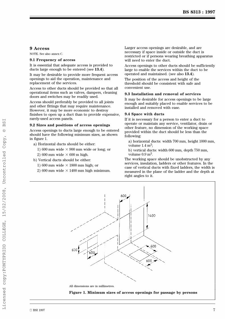
All dimensions are in millimetres.
Figure 1. Minimum sizes of access openings for passage by persons
9 AccessNOTE. See also annex C.
9.1 Frequency of access
It is essential that adequate access is provided toducts large enough to be entered (see 13.4).
It may be desirable to provide more frequent accessopenings to aid the operation, maintenance andreplacement of the services.
Access to other ducts should be provided so that alloperational items such as valves, dampers, cleaningdoors and switches may be readily used.
Access should preferably be provided to all jointsand other fittings that may require maintenance.However, it may be more economic to destroyfinishes to open up a duct than to provide expensive,rarely-used access panels.
9.2 Sizes and positions of access openings
Access openings to ducts large enough to be enteredshould have the following minimum sizes, as shownin figure 1.
a) Horizontal ducts should be either:
1) 600 mm wide 3 900 mm wide or long; or
2) 600 mm wide 3 600 m high.
b) Vertical ducts should be either:
1) 600 mm wide 3 1800 mm high; or
2) 600 mm wide 3 1400 mm high minimum.
Larger access openings are desirable, and arenecessary if space inside or outside the duct isrestricted or if persons wearing breathing apparatuswill need to enter the duct.
Access openings to other ducts should be sufficientlylarge to enable the services within the duct to beoperated and maintained. (see also 13.4).
The position of the access and height of thethreshold should be consistent with safe andconvenient use.
9.3 Installation and removal of services
It may be desirable for access openings to be largeenough and suitably placed to enable services to beinstalled and removed with ease.
9.4 Space with ducts
If it is necessary for a person to enter a duct tooperate or maintain any service, ventilator, drain orother feature, no dimension of the working spaceprovided within the duct should be less than thefollowing:
a) horizontal ducts: width 700 mm, height 1000 mm,volume 1.4 m3;
b) vertical ducts: width 600 mm, depth 750 mm,volume 0.9 m3.
The working space should be unobstructed by anyservices, insulation, ladders or other features. In thecase of vertical ducts with fixed ladders, the width ismeasured in the plane of the ladder and the depth atright angles to it.
Licensed copy:PONTYPRIDD COLLEGE, 15/02/2008, Uncontrolled Copy, © BSI
www.bzfxw.com
8 BSI 1997
BS 8313 : 1997
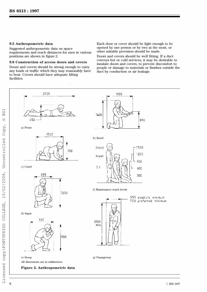
a) Prone
b) Kneel
c) Crawl
f) Maintenance reach levels
d) Squat
e) Stoop g) Passageway
All dimensions are in millimetres.
Figure 2. Anthropometric data
9.5 Anthropometric data
Suggested anthropometric data on spacerequirements and reach distances for men in variouspositions are shown in figure 2.
9.6 Construction of access doors and covers
Doors and covers should be strong enough to carryany loads or traffic which they may reasonably haveto bear. Covers should have adequate liftingfacilities.
Each door or cover should be light enough to beopened by one person or by two at the most, orother suitable provision should be made.
Doors and covers should be well fitting. If a ductconveys hot or cold services, it may be desirable toinsulate doors and covers, to prevent discomfort topeople or damage to materials or finishes outside theduct by conduction or air leakage.
Licensed copy:PONTYPRIDD COLLEGE, 15/02/2008, Uncontrolled Copy, © BSI

www.bzfxw.com
BSI 1997 9
BS 8313 : 1997
Ladder width 380 min. 450 optimum
Distance between side walls 600 min.
Rung distance c 225 to 250
Rung diameter d 20 to 40
(h) Ladder
Width for one man 600 to 750
Width for two men 1100 min.
Riser b 184 optimum
Tread c 240
(i) Steps
Width 530 to 600 with handrails
600 min. between side walls
Riser b 250 maximum
Tread width c 80 to 150
(j) Inclined ladder
Width 750 min. to 1100 optimum
(k) Ramp
All dimensions are in millimetres.
Figure 2. Anthropometric data (concluded)
Doors and covers should be hinged or completelyremovable. Sliding doors should not be used. Alldoors should open outwards from the duct interior.Hinged hatch covers in floors should openthrough 180 Ê or be provided with a self-lockingdevice to hold the hatch open. Doors of ducts thatare large enough to be entered should be openablefrom the inside of the duct.
Heavy trench covers do not usually require securing.Other access covers and doors should preferably besecured by budget locks (see 3.16).
Continuous trench covers generally requireindividual adjustment during installation to ensureaccurate alignment of the surfaces with adjacentfloor surfaces and to eliminate any tendency to rockupon the bearing points. It is, therefore importantthat individual sections of trench covers benumbered or marked to ensure that they are placedin correct sequence.
9.7 SecuritySpecial procedures or devices controlling the use ofdoors and access covers may be needed, particularlyif a hazard may arise from unauthorized use.
Licensed copy:PONTYPRIDD COLLEGE, 15/02/2008, Uncontrolled Copy, © BSI
www.bzfxw.com
10 BSI 1997
BS 8313 : 1997
10 Protection of services in ducts
10.1 Mechanical damage
Services should be protected from accidental andmalicious damage by suitable positioning orenclosure.
10.2 Condensation
Condensation should be prevented by suitable choiceof insulation, ventilation and heating.
10.3 Corrosion
Corrosion should be minimized by choice of suitablematerials and combinations of materials, by keepingducts and services dry and by application of suitablepaint or other protective coatings. Relevantinformation is given in BS 5493 and PD 6484.
10.4 Frost
Services liable to frost damage should be positionedin frost-free places where possible. If this is notpossible, they should be protected by insulationand/or heating. The latter should be thermostaticallycontrolled. Particular care should be taken whenwater services are run in ventilated ducts.
10.5 Thermal expansion
Provision should be made for thermal expansion ofservices without imposing excessive loads on thestructure, fixings or services.
10.6 Differential movement
It is common for services to have to accommodatedifferential movement, particularly, but not only, atservice entry and exit points. Services shouldtherefore be designed so that they can accommodatethe expected movement without damage. Advice onhow much movement can occur may need to besought.
10.7 Provision of adequate support
In selecting the method of supporting services,provision should be made for the overall dimensionsof the services where these are to be thermallyinsulated, and for the preservation of anymoisture-proof layer.
Typical fixings and supports are specified in BS 3974and BS 5572.
11 Drainage of service ducts11.1 General
Drainage should be provided in ducts to dispose ofliquids from leakage or infiltration.
Special consideration should be given to thedrainage of flammable, toxic or corrosive liquids.
11.2 Discharge to building drainagesystem, etc.
Drains from ducts should discharge to the buildingdrainage system, a soakaway or watercourse, etc., ifthis is acceptable to the water authority. If sufficientfall is not available, a sump with an automatic pumpand high level alarm should be provided. A warningpipe or other suitable means should be provided. A
warning pipe or other suitable means should indicatethat liquid has escaped within or has entered theduct. Precautions should be taken to maintain trapseals to prevent the entry of rodents, for instance byconnecting the discharge from a sanitary applianceto the trap. Precautions should also be taken againstback flow drains into underground ducts.
11.3 Collection in holding tank
If the water authority does not accept discharge tothe building drainage system, etc., drains from ductsshould discharge to a holding tank. The capacity ofthe tank should be chosen in relation to the amountof liquid likely to escape from a failed service.Provision should be made for emptying the holdingtank to a disposal contractor's vehicle or othersuitable recipient. An alarm should indicate thatliquid has entered the tank, so that the cause can beestablished and remedied.
11.4 Retention within the duct
If there is a significant probability of a liquid serviceleaking and causing damage but it is impractical toprovide drainage, the duct should be madewatertight and arrangements made for removing anddisposing of liquid retained in the duct after a leak.An alarm should indicate that there is liquid in theduct, so that the cause can be established andremedied.
11.5 Watertightness
Ducts below ground level which may be subject toexternal water pressure should be watertight.(See CP 102.)
12 Ventilation of service ducts
12.1 General
It is recommended that building service ducts shouldbe ventilated regardless of the services they contain.
Ventilation for persons within ducts is coveredin 12.2, for the control of hazardous leaks in 12.3,and for the control of environmental effects,e.g. condensation or overheating in 12.4. Satisfyingthe single largest requirement should be satisfactoryin all cases.
The provision for ventilation should be so designedas not to decrease the fire safety of the building.
Ventilation openings provided in accordancewith 12.1 to 12.4 should, where necessary, because afire resisting division is passed, be fitted withdevices, e.g. fire resisting doors or dampers, that willclose automatically in case of fire. Considerationshould be given to the provision of indicators toshow whether the device is open or closed.NOTE. Ducts with a cross-sectional area of less than 0.05 m2
which convey only services in the following list need not beventilated other than as required in 12.2 or to prevent overheating:
a) ventilation, air conditioning, warm air heating;
b) drainage in houses, offices and shops, except food shops;
c) electric power and telecommunications;
d) substances of groups 4 and 6 (see 7.2.2);
e) vacuum pipelines.
Licensed copy:PONTYPRIDD COLLEGE, 15/02/2008, Uncontrolled Copy, © BSI

www.bzfxw.com
BSI 1997 11
BS 8313 : 1997
12.2 Ventilation for persons
Work carried out in confined spaces is potentiallyhazardous and guidance on the precautions to betaken is given in annex C.
Ventilation for persons within ducts may be achievedeither by permanent means or by providingventilation prior to and during occupation.
The ventilation applied should be capable ofproviding respirable air for persons whilst working.In some instances additional air may be required tocater for the work being undertaken, e.g. removal ofheat or dilution of welding fumes.
BS 5925 provides information on the quantities of airrequired. (See also Health and Safety ExecutiveGuidance Note EH22 [14].)
12.3 Safety ventilation
12.3.1 Ventilation should be provided to dilute anyanticipated or reasonably foreseeable leakages offlammable, toxic or corrosive gases to a safe level.
Advice on occupational exposure limits of airbornesubstances hazardous to health is available in Healthand Safety Executive Guidance Note EH40 [15].
For flammable gases or vapours small leaks shouldbe diluted below 25 % of the lower flammable limit(sometimes referred to as LFL or LEL). Where it isnot reasonably practicable to satisfy the above,see 12.3.4.
Where oxidizing gases are being distributed, theventilation air requirement should be such as to limitthe concentration of the leaked oxidizing gas in airto less than 1 % by volume.
Natural ventilation is preferred.
Pockets in roofs or floors where lighter-than-air orheavier-than-air gases respectively may accumulateshould be avoided.
The ventilation rates should be based upon thesensitivity of pressure testing and maintenanceprocedures applied for each service.
NOTE 1. The minimum areas for natural ventilation shown intable 1 should be more than adequate for most applications.
NOTE 2. Builder's ducts having a small cross-sectional area andvolume (i.e. 10 000 mm2 or less and 0.1 m3 or less respectively)may not need the provision of ventilation to the full requirementsof table 1 where the duct is contained within one compartmentand that compartment has adequate ventilation. Some ventilationbetween the duct and the compartment may, however, be requiredfor dispersion of leaks or to limit temperatures (see 12.3.2).
NOTE 3. It is generally not considered necessary to provideventilation in some small internal structures (e.g. partition walls orceiling spaces) where medical piped services are installed ofall-welded, brazed or joint-free construction. In such cases thesystem should be subjected to rigorous soundness testingprocedures. Guidance for soundness testing of such services inhospitals is given in Department of Health Technical ReportsHTR 2022 [16] and HTR 2023 [17].
Table 1. Free area of ventilation opening fordispersal of small leaks
Cross-sectional area of ductm2
Minimum free area of eachopening
Not more than 0.05 Cross-sectional areaof duct
More than 0.05 but notmore than 7.5
0.05 m2
More than 7.5 1/150th of area of duct
12.3.2 Duct ventilation openings should lead to safeplaces, preferably the open air. Ducts containedsolely within a room or an occupied space and notcontaining group 3 services may be ventilated withinthat room provided that the room is ventilated (seealso 12.3.3).
The free area of such ventilation openings and thedistance between them should be based onconsideration of the relevant factors which affect airmovement, including the location, size andconfiguration of the duct, on the physical propertiesincluding the relative density of the gases or vapoursinvolved on factors influencing the potentialmagnitude of any leakages.
Ventilation openings should be located such that airmovement can occur within the duct, e.g. at the topand bottom or at each end, and at intervals alonglong horizontal ducts.
In general, the larger the interval between openingsin horizontal ducts, the greater is the need for avertical component to the duct at one end togenerate air movement.
12.3.3 Where there are openings in false orsuspended ceilings or floors through which air canpass between the room and the service space, thesemay be counted as part of the open area required forventilation of the service space as long as they areunlikely to be blocked.
The equivalent minimum free area of these openingsshould be calculated from laboratory tests or dataprovided by the ceiling or flooring manufacturerbased on a 1 Pa pressure differential across it.
12.3.4 Where it is impracticable to ventilate a ductthat conveys flammable or oxidizing gases,flammable liquids or toxic substances, alternativeprecautions should be taken.
Suggested methods are as follows.
a) The pipe(s) conveying the gas or liquids shouldbe continuously sleeved through the unventilatedduct with the sleeve ventilated at one or both endsinto a ventilated area or room or duct;
b) The unventilated duct should be filled with acrushed inert infill to reduce to a minimum thevolume of any gas or liquid that may accumulate.The infill material should be dry, non absorbent,chemically neutral and non combustible,e.g. crushed slate chippings or dry washed sand.NOTE. See note 3 of 12.3.1 for medical services.
Licensed copy:PONTYPRIDD COLLEGE, 15/02/2008, Uncontrolled Copy, © BSI

www.bzfxw.com
12 BSI 1997
BS 8313 : 1997
12.4 Ventilation for overheating orcondensation
In some circumstances ventilation of ducts may benecessary to prevent overheating or condensation.Wherever possible natural ventilation should beused.
13 Fire precautions13.1 The objects of fire precautions
13.1.1 The objects of fire precautions are:
a) to prevent the occurrence of fire;
b) to detect a fire in its early stages;
c) to provide means of escape for the occupants;
d) to prevent the spread of fire and smoke;
e) to extinguish the fire.
13.1.2 Unless suitable precautions are taken, serviceducts may be:
a) a place where fire starts;
b) a place where fire grows undetected;
c) a place where persons become trapped;
d) a route for the spread of fire and smoke;
e) a place where fire is difficult to extinguish.
13.2 Prevention of fire
13.2.1 The location and construction of servicesand ducts within buildings should take into accountthe fire hazards to the services from fires which canoccur in the building or in the duct, and the hazardsto the building from a major failure of the services.
In some special cases it may be necessary to provideliquid or gas monitoring or explosion reliefs withinthe duct.
13.2.2 If combustible materials are considered foruse within or as part of a service duct, the extent towhich they will increase the fire loading, thenecessary provision of cavity barriers and theproduction of smoke and toxic gases should becarefully assessed. Careful consideration should begiven to the potential fire and smoke hazard inherentin combustible insulation. (See BS 5422 andBS 5970.)
13.2.3 Ducts to which access is provided should bedesigned to be cleanable (see 19.3). Accumulationsof rubbish, dust or grease can easily be ignited.Particular care should be taken that insulation doesnot become contaminated by flammable liquids. (SeeBS 5422 and BS 5970.)
13.2.4 Sources of ignition should be avoided wherepossible. Smoking should be prohibited in serviceducts. Suitable precautions should be taken whenoperations involving heat, such as soldering andwelding, are to be carried out inside ducts (seeHealth and Safety Executive Guidance NotesEH 54 [18] and EH 55 [19]. In high fire risk areas,sparks from power or hand tools are dangerous.Heat should not be applied to pipes or plant that hascontained flammable substances unless it is safe todo so (see also 19.2).
Consideration should be given to the provision ofample separation between flammable piped servicesand electrical equipment. Where this is notpracticable, the construction of the piped serviceshould be joint free in the vicinity of the electricalequipment or consideration should be given to theneed for the application of explosion proofequipment (see BS 5345 : Part 1 and Part 2,BS EN 50014 and the British Approvals Service forElectrical Equipment in Flammable Atmospheres(BASEEFA) list [20] published by the Health andSafety Executive.
13.2.5 Vertical ducts conveying power cables shouldbe provided with internal barriers as required byBS 7671 or adequate ventilation should be providedto prevent overheating of cables throughout theirlength.
13.2.6 If flammable or oxidizing services are to beinstalled in a ceiling void or floor void, either theservices should be enclosed in separate duct(s) orpipe sleeve(s) within the void, or the void should beconsidered as a duct and the necessary ventilationprovided.
If group 1, 2 or 3 services are to be installed in aceiling or floor void they should be enclosed in aduct which is ventilated to a safe position.
If the services are enclosed in a separate duct orpipe sleeve within the void, the duct(s) or pipesleeve(s) should be sealed from the void and shouldbe in accordance with this standard. If the servicesare not enclosed within a separate duct or pipesleeve within the void, the void should be consideredto be a service duct.
13.2.7 The following factors should be carefullyconsidered when locating services in a separate ductwithin a void:
a) ventilation of the void;
b) provision of cavity barriers;
c) access to services.
13.3 Detection and alarm of fire
13.3.1 Where ducts are large enough for passage ofpersons, provision should be made for giving alarmof fire.
13.3.2 If the building has a fire alarm system, thealarm sounders should be audible within such ductsand manual call points should be situated inside, andadjacent to, each exit from the duct.
13.3.3 If the building has a fire detection system,consideration should be given to such system beingextended into service ducts of whatever size.
13.3.4 Any fire alarm or fire detection and alarmsystem should be in accordance with BS 5839 :Part 1.
Licensed copy:PONTYPRIDD COLLEGE, 15/02/2008, Uncontrolled Copy, © BSI

www.bzfxw.com
BSI 1997 13
BS 8313 : 1997
13.4 Means of escape
13.4.1 It is essential that adequate provision formeans of escape in case of fire is provided fromducts that are large enough for passage of persons.In this connection, consideration should not only begiven to the need to escape from any duct in whichfire has broken out but also so prevent anyonewithin a duct being trapped by the outbreak of fireelsewhere in the building.
13.4.2 Exits should be provided in such a number,and be so sited, that any person confronted by anoutbreak of fire within the duct, or trapped by fireexternal to the duct, can make a safe escape. Whereany duct (or section) is provided with two or moreexits, such exits (unless affording access direct tothe external air) should deliver to independentalternative escape routes from the building.
13.4.3 All doors affording escape from and withinducts should open in the direction of escape andshould be fitted only with simple fastenings that canbe operated from the escape side of the doorwithout the use of a key. However, provision mayneed to be made to prevent unauthorized entry intothe duct.
13.4.4 Doors and openings into and within ductslarge enough for the passage of persons should be ofsuch a size as to allow personnel to move throughwithout difficulty. Consideration should also be givento their being large enough to permit the removal ofan unconscious person and for their use by anyonewearing breathing apparatus.
13.4.5 All exits should be clearly identified withsigns in accordance with BS 5499 : Part 1.
13.4.6 In intricate or extensive ducting,consideration should be given to the provision of thefollowing:
a) artificial lighting;
b) escape lighting in accordance with BS 5266:Part 1;
c) telephones at suitable positions to enablepersons trapped to summon help.
13.5 Prevention of spread of fire and smoke
13.5.1 Service ducts and their contents should bedesigned, constructed and maintained so that theydo not impair the building's resistance to fire.
13.5.2 Where a service duct passes from onecompartment to another, or through any other fireresisting division in a building, the fire separationshould be maintained by:
a) constructing the duct so that it has the fireresistance recommended in 13.5.4; or
b) continuing the fire resisting division across theduct; or
c) a combination of a) and b).
13.5.3 Where a service duct or pipe sleeve iscontained within, or passes through, a protectedescape route, adequate precautions should be takento ensure the safety of the escape route, e.g. by theuse of a fire resisting duct or the provision of cavitybarriers and/or fire stopping.
13.5.4 A fire resisting duct or pipe sleeve shouldhave a fire resistance at least equal to the higheststandard required for any of the fire resistingdivisions it crosses.
13.5.5 Any openings provided within the enclosuresof fire resisting ducts or pipe sleeves should be keptto a minimum and fitted with doors or panels havingnot less than half the fire resistance required for theduct enclosure, with a minimum of 30 min integrity.
13.5.6 All fire doors should be fitted with aself-closing device (other than rising butt hinges).However, where not required as an exit, such doorsor panels may be fitted with means to enable themto be kept locked shut when not in use in lieu oftheir being self-closing.
All fire doors should be marked, at eye level, withthe appropriate fire safety sign in accordance withBS 5499 : Part 1.
13.5.7 Where any pipe penetrates a fire resistingdivision or enclosure it should either:
a) be contained within a duct having a fireresistance recommended in 13.5.4 (e.g. protectedshaft); or
b) be protected by a sealing system whichmaintains the fire resistance of the elementpenetrated; or
c) have a nominal internal diameter not exceedingthe relevant dimension given in connection withbuilding regulations;
d) have nominal size which does notexceed 300 mm, and:
1) should be of welded steel construction, witha wall thickness of not less than 6 mm;
2) should be constructed to accommodate suchpenetration; and
3) should be enclosed in a sleeve that is sealedto the structure and to the pipe in such amanner as not to reduce the fire resistance ofthe division.
13.5.8 Where a service passes through a fireresisting division or enclosure, and the service is notcontained within a protected shaft, see 13.5.7a), anyopening for the service should be kept as small aspossible and should be fire stopped.
13.5.9 Any insulation to services should notpenetrate a fire resisting division or enclosure if thiswould impair the resistance to fire of the division orenclosure.
Licensed copy:PONTYPRIDD COLLEGE, 15/02/2008, Uncontrolled Copy, © BSI

www.bzfxw.com
14 BSI 1997
BS 8313 : 1997
13.5.10 Where a duct is contained wholly withinone fire compartment, it will not normally require afire resisting enclosure since the possibility of firespread to another fire compartment via the duct willnot exist. There may be a considerable hazard wheresmall areas of high fire risk such as kitchens orstores are included in the same fire compartment assleeping accommodation. In these cases ducts arenormally horizontal, and the risk is greater if theyare at a high level where they may be subjected tothe worst conditions of flame and heat from a fire. Insuch circumstances, consideration should be given tothe duct enclosures, including any access orinspection panels in the high fire risk areas, beingfire resisting.
A fire resisting suspended ceiling does notnecessarily check the spread of fire from the roombelow to services within the ceiling void or serviceducts connected to it.
13.5.11 Cavity barriers or fire stopping should beprovided within any service duct not enclosed withinfire resisting construction:
a) for vertical ducts, at every floor level. If theduct contains uPVC pipework the duct enclosuresshould resist smoke penetration;
b) for horizontal ducts, at approximately 8 mintervals, where either:
1) the duct enclosures are not constructed ofmaterials of limited combustibility; or
2) substantial amounts of combustible materialsare contained within the duct, e.g. as thermalinsulation.
Consideration should also be given to providingcavity barriers or fire stopping at every point wherea duct passes the boundary of a room or corridor.
13.5.12 In long ducts provided with means ofescape in accordance with 13.4, provision should bemade for preventing the unrestricted spread of fireand smoke between exits.
13.5.13 No means of access to service ductcovered in 13.5.11 should be provided from:
a) a protected stairway affording the sole means ofescape from a building or part of a building;
b) sleeping accommodation; or
c) a dwelling, if there is means of access to thesame section of duct from an indoor space whichis not part of that dwelling.
13.6 Fire fighting
13.6.1 Sufficient and suitable access should beprovided to major ducts to enable the fire service toclear the ducts of smoke and to fight a fire insidethem.
13.6.2 All doors, ground lights and ventilator shaftsdesigned for fire brigade use should be clearlymarked on the exterior as to their function,e.g. `SMOKE OUTLET FROM SERVICE DUCT'.
The recommendations given in BS 5378 and BS 5499should be followed.
13.6.3 Major service ducts and important features,such as ventilators and gas isolating valves should beshown on the drawings available to the fire service.
13.6.4 Portable fire extinguishers, hose reels,sprinklers and fire extinguishing gas systems shouldbe provided in service ducts as appropriate.
Any total flooding or automatic fire extinguishersmounted in ducts should be in accordance withBS 5306 : Part 0, and BS 7273 : Part 2. Furtherinformation is given in Health and Safety ExecutiveGuidance Note GS16 [21]. Particular attention shouldbe paid to the safety of persons within service ducts.
14 Other safety precautions
14.1 General
The safety of the building and all occupants andmaintenance personnel should be provided forduring the design of service ducts and services.
The nature of the operations to be carried out withinthe ducts should be assessed in detail, in order todetermine the facilities that operatives will need inorder to work safely.
Special consideration should be given to the safetyof personnel required to enter and work inside theducts, taking into account those hazards likely to beencountered (see 19.2) both during construction anduse.
14.2 Hazards
As early as possible during the design of a duct, anassessment should be made of the possible dangersto personnel and to the building. Hazards may arisefrom the arrangement of the ducts or from theservices inside them.
For example, personnel may need designedprotection against flooding in some ducts,particularly those below ground level, and in suchcases a means of drainage will be required. Whereflooding is probable, adequate means of rapid escapeshould be provided for personnel.
Other hazards can be created by the effects ofmaterials such as fluids which may possibly enter aduct. Apart from flooding, such dangers as fumes,explosion, bacteria, physical and chemical processes,including extremes of temperature, pressure andhumidity are typical possibilities. These are not likelyto be common hazards but if they are possible thenexpert advice should be obtained very early in thedesign stage in order to resolve the problems.
Attention is also drawn to the hazards associatedwith asbestos and the related legal controls, see 5.2.
14.3 Duct interiors
Interiors of ducts should be simple and regular inshape and sudden changes in shape and floor levelsshould be avoided.
Licensed copy:PONTYPRIDD COLLEGE, 15/02/2008, Uncontrolled Copy, © BSI

www.bzfxw.com
BSI 1997 15
BS 8313 : 1997
Pipelines or services within the ducts should besuitably insulated and protected to avoidendangering personnel. Step irons and handrailsshould not be in contact with hot pipes.
Unexpected obstructions or projections by the ductor by the services and equipment within should belimited by careful design and installation.
Services and equipment should be arranged neatlywithin ducts and should be readily accessible formaintenance.
14.4 Protection against falls
It may be necessary to take special precautionsagainst the possibility of personnel falling withinducts.
No sudden drop should occur over the threshold ofan entrance to a duct. If the floor level of the duct isbelow that of the floor outside, the level of the latterwhere possible should be continued through thethreshold to give a platform of minimumdimensions 750 mm by 750 mm.
Where a platform cannot be provided, the entranceshould be fitted with a guard rail and sill when adifference in levels occurs over the threshold. Accessopenings to under-floor ducts should be protected bytemporary guard rails when open.
Platforms and staircases within ducts should befitted with handrailing 1200 mm high with a midrailand toeboard, and an entrance to a stair or ladderfrom a platform should be fitted with a safety bar.
Suitable fixed ladders, stairs, steps or ramps shouldbe provided in vertical ducts or where there is achange in floor level in a horizontal duct.Recommended dimensions for these can be found inthe annexes.
Fixed ladders should conform to BS 4211. As analternative to the provision of safety cages asspecified in BS 4211, other suitable means ofproviding safety on ladders can be employed,e.g. suitable systems for use with safety belts, whichhelp in the release of a person who has collapsed.
In vertical ducts, anchors for attaching the safety lineof a harness should be provided on platforms and inthe side of the duct at intervals of not morethan 2 m. Anchors should conform to BS 5845, andsafety belts or harnesses should conform toBS EN 354, BS EN 358, BS EN 361, BS EN 365 andBS 2830.
14.5 Electrical power
The provision of electrical power within ducts is notnormally necessary, however, where needed it isimportant to consider the problems of high voltagesand of trailing leads.
14.6 Lighting
A lighting installation should be provided withinducts large enough to be entered, particularly ataccess points.
Lights should be controlled by switches placed at auniform height and at regular intervals. Switchesshould always be provided at access points.
Consideration should be given to the provisions ofemergency lighting, which should be actuatedautomatically when the normal lighting fails, or atleast to placing alternative lamps on two differentcircuits.
Explosion protected or waterproof fittings andswitches should be used where appropriate(See BS 5345 : Parts 1 and 2.)
14.7 Equipotential bonding
All simultaneously accessible extraneous and/orexposed conductive parts should meet therequirements of BS 7671.
14.8 Alarm systems
Suitable alarm systems should be provided if therecommendations of clause 13 do not ensure safety.
14.9 Means of escape
Suitable means of escape should be provided if therecommendations of clause 13 do not ensure safety.
15 Service entries and exits
15.1 The following general principles should beobserved in the design of service entries and exits.
a) The service should be supported in such a waythat differential movement is accommodated orprevented;
b) The building and its foundations should not beweakened;
c) The service should be sleeved where it passesthrough the building structure;
d) The space between the service and the sleeveshould be sealed at the point of entry with a nonhardening plastic material to prevent the passageof water, gas and vermin. (See BS 6213.)Consideration may be given to using cable glandsor cable transits as an alternative, whereapplicable;
e) The service should pass through or under thebuilding structure by the shortest practical route.
15.2 The design of service entries and exits shouldbe agreed with the utilities as early as possible.
Advice on the design of service entries and exits canbe found in the following publications:
a) gas pipes: IGE publication IGE/UP/2 [12];
b) telephone, telegraph and data communication:BS 6701;
c) water supply: BS 6700.
Licensed copy:PONTYPRIDD COLLEGE, 15/02/2008, Uncontrolled Copy, © BSI
www.bzfxw.com
16 BSI 1997
BS 8313 : 1997
1) Under The Gas Safety (Installation and Use) Regulations 1994.
16 Identification and marking
16.1 Marking of ducts
16.1.1 Marking of duct entrances
Access doors and panels should be marked withpre-entry precautions, e.g. work permits.
16.1.2 Diagram of duct system
If a duct system is complex and ducts are largeenough to be entered, a diagram of the systemshould be fixed to the inside of the duct at eachaccess point. The diagram should carry a `you arehere' indication. The contents of each duct should beindicated.
16.1.3 Emergency notices
In ducts large enough for persons to enter, it isessential to provide, at suitable locations, conciseactions to be taken in the event of an emergencyarising within the duct.
16.2 Marking of services in ducts
Consideration should be given to marking services atappropriate points including the direction of flow.Where confusion could lead to a hazard, servicesshould be appropriately marked.
Valves, dampers, switches and other controls shouldbe clearly marked to indicate what service orfunction they control.
Some services need to be marked to conform tostatutory requirements.
The recommendations of BS 1710 and the Heatingand Ventilating Contractors' Association's DW 142should be followed [22].
16.3 Marking of other features
It is essential that sufficient and suitable marking isprovided for persons inside the duct to easily findescape routes, exits, alarms, telephones, lightswitches, etc.
The recommendations of BS 5378 and BS 5499 :Parts 1, 2 and 3 should be followed.
17 Duct construction
17.1 General
Prefabrication and pre-assembly in factoryconditions of components and assemblies can offersignificant advantages of speedier erection on site,improved quality and lower cost.
For large projects, the production of speciallydesigned items off site may be worthwhile.
17.2 Workmanship
Service ducts are often expected not merely to hideservices from view, but to support them, withstandexpansion forces, contain leakages of liquids orgases, resist the spread of fire and many otherfunctions. A good standard of workmanship isessential if they are to be able to fulfil theseobjectives.
Joints and seals in both ducts and services are weakpoints whose number should be minimized and towhich particular attention should be given.
For site work, consideration should be given to thesetting up of a workshop on site where componentsand assemblies can be formed and fabricated moreeasily than in a duct.
17.3 Sequence of work
As space in ducts is usually limited, carefulconsideration should be given to the order in whichthe ducts and their contents are to be erected toensure that all trades have the necessary access andthat earlier work is not likely to be damaged byfollowing trades.
17.4 Holes
Attention should be paid to minimizing the numberof holes in the duct enclosure.
Holes should not be cut through structural memberswithout the approval of the structural engineer.
Where a service passes through a wall or otherconstruction, a neat hole should be provided for thepassage of the service. The hole should be as smallas reasonably practical.
Where a close-fitting hole for the passage of aservice is cut through a construction less than 25 mmthick or through a solid construction of a strongmaterial and vibration and movement are expectedto be small, the service need not be sleeved butshould have wall plates. In other cases the serviceshould be sleeved and the construction made goodto the sleeve1).
The hole around a service should be sealed toprevent the passage of dirt, insects, water, gases, andsound, etc. Suitable materials for filling the holeshould be selected with reference to BS 6213.
Services passing through fire resisting constructionsshould maintain the required fire resistance(see 13.5.8).
It is permissible for several services to pass throughthe same hole if satisfactory support, sealing and firestopping can be achieved.
There should be no joints, other than welded joints,in services where they pass through constructions.
Licensed copy:PONTYPRIDD COLLEGE, 15/02/2008, Uncontrolled Copy, © BSI

www.bzfxw.com
BSI 1997 17
BS 8313 : 1997
17.5 Cleaning
Particular attention should be paid to cleaningduring and after construction, as service ducts makea convenient rubbish dump.
17.6 Fire safety
All reasonable precautions should be taken to avoidthe outbreak of fire. Work involving the use of nakedflames is particularly hazardous and all such workshould be examined at short intervals immediatelyfollowing its cessation. It is essential that thecontractor impresses on his workmen the dangersinvolved in the careless use of naked flames inproximity to combustible material, the disposal ofmatches and cigarettes etc. and the accumulation ofrubbish on site. A portable fire extinguisher shouldbe readily available. (See BS 5306: Part 0).
18 Inspection and testing
18.1 Inspection should be maintained throughoutthe period of construction, to ensure that work hasbeen done correctly and has not been subsequentlydamaged.
18.2 At completion, the cleaned ducts should bethoroughly inspected and tested. Some points thatshould be checked are listed below:
a) duct ventilators and any associated firedampers;
b) duct drainage;
c) duct lighting;
d) alarms, telephones, etc.;
e) marking;
f) fit and lubrication of doors, hatchways, accesspanels;
g) fire extinguishing equipment;
h) acceptance certificates;
i) drawing showing location of isolators orisolating valves.
19 MaintenanceNOTE. See also BS 8210.
19.1 Operation and maintenance instructions
Operation and maintenance instructions should besupplied, containing complete sets of `as-fitted'drawings and specifications, instruction manuals forequipment, etc.
19.2 Routine inspections and maintenancework
Accessible ducts and services should be inspected atregular intervals. Records of the inspections and ofany work done should be kept and signed as part ofa policy of planned maintenance.
Careful consideration should be given to any hazardsinvolved in entry into and work within ducts. If anyhazard is expected , the procedure set out in Healthand Safety Executive Guidance Note GS5 [23] or theIGE publication IGE/SR/5 [24]should be followed.
Guidance on permits to work is also given inGS5 [23].
It is essential that appropriate safeguards be taken ifthere is any risk of exposure to asbestos, see 5.2.
19.3 Cleaning and painting
Ducts that in normal use are liable to accumulatedust, grease or other flammable matter should beprovided with access traps to facilitate inspectionand cleaning. Ducts should not be used for storagepurposes and flammable materials should not beallowed to accumulate, particularly throughmaintenance activities. Ducts should be cleaned asnecessary.
The cleaning of a duct after any form of hazardouscontamination is a job for specialists.
Regular inspection should be made for the detectionof vermin and any necessary measures taken fordisinfestation.
Consideration should be given to repainting ferrouspipe fixings and other iron work under a plannedmaintenance system for protection against corrosionwhere adverse site conditions are anticipated. Forprecautions in spraying of highly flammable liquid,reference should be made to Health and SafetyExecutive Guidance Note EH9 [25].
19.4 Fire safety
Before any works of maintenance are carried out,consideration should be given to the extent of anyfire hazards involved, and the effect of any fire onthe occupants or operation of the building.Appropriate precautionary measures should be takenwhere necessary, for example by temporarilyrelocating occupants who may be put at risk shoulda fire start. All reasonable precautions should betaken to avoid the outbreak of fire. Smoking shouldbe prohibited in ducts and `no smoking' rulesapplicable in other areas of the building should beobserved by maintenance workers. It is essential thatfire escape routes are kept unobstructed. A portablefire extinguisher should be readily available. Seealso 17.6.
Licensed copy:PONTYPRIDD COLLEGE, 15/02/2008, Uncontrolled Copy, © BSI
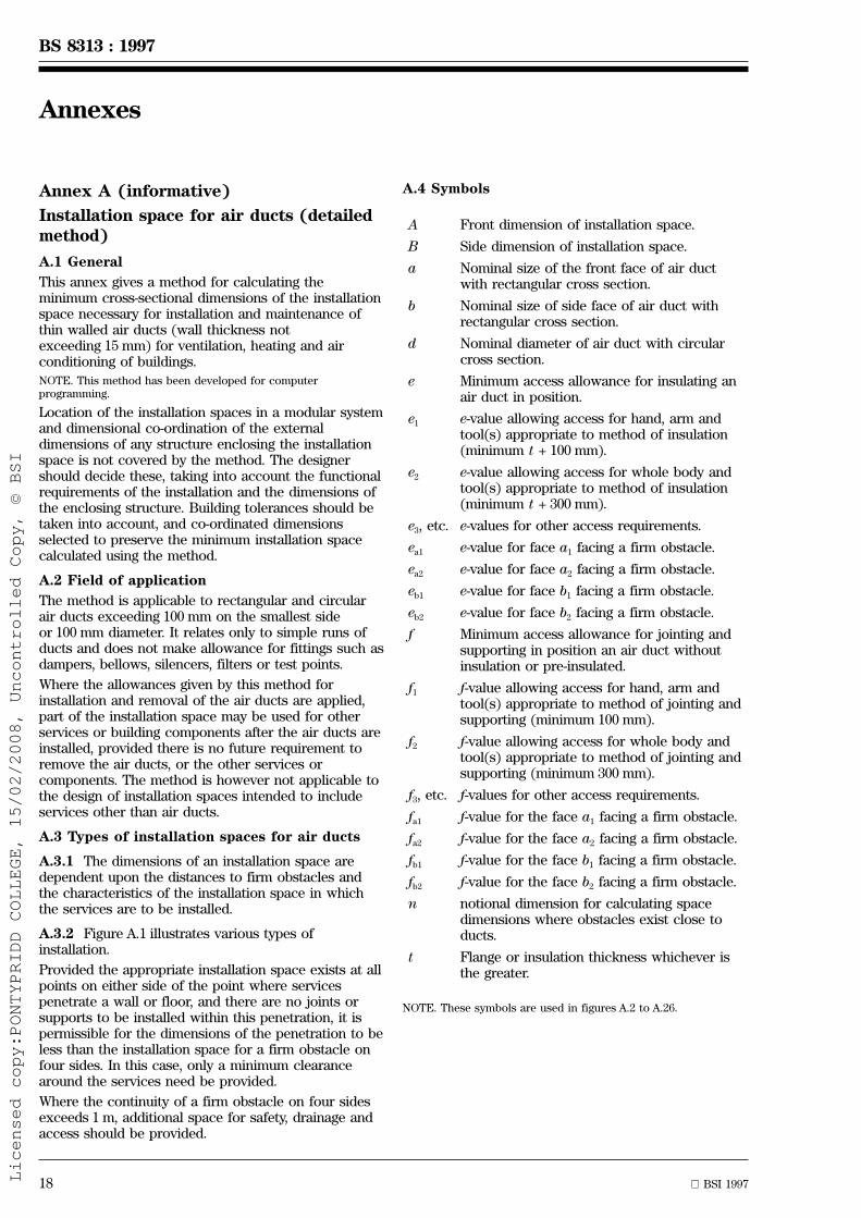
www.bzfxw.com
BS 8313 : 1997
18 BSI 1997
Annexes
Annex A (informative)
Installation space for air ducts (detailedmethod)
A.1 General
This annex gives a method for calculating theminimum cross-sectional dimensions of the installationspace necessary for installation and maintenance ofthin walled air ducts (wall thickness notexceeding 15 mm) for ventilation, heating and airconditioning of buildings.
NOTE. This method has been developed for computerprogramming.
Location of the installation spaces in a modular systemand dimensional co-ordination of the externaldimensions of any structure enclosing the installationspace is not covered by the method. The designershould decide these, taking into account the functionalrequirements of the installation and the dimensions ofthe enclosing structure. Building tolerances should betaken into account, and co-ordinated dimensionsselected to preserve the minimum installation spacecalculated using the method.
A.2 Field of application
The method is applicable to rectangular and circularair ducts exceeding 100 mm on the smallest sideor 100 mm diameter. It relates only to simple runs ofducts and does not make allowance for fittings such asdampers, bellows, silencers, filters or test points.
Where the allowances given by this method forinstallation and removal of the air ducts are applied,part of the installation space may be used for otherservices or building components after the air ducts areinstalled, provided there is no future requirement toremove the air ducts, or the other services orcomponents. The method is however not applicable tothe design of installation spaces intended to includeservices other than air ducts.
A.3 Types of installation spaces for air ducts
A.3.1 The dimensions of an installation space aredependent upon the distances to firm obstacles andthe characteristics of the installation space in whichthe services are to be installed.
A.3.2 Figure A.1 illustrates various types ofinstallation.
Provided the appropriate installation space exists at allpoints on either side of the point where servicespenetrate a wall or floor, and there are no joints orsupports to be installed within this penetration, it ispermissible for the dimensions of the penetration to beless than the installation space for a firm obstacle onfour sides. In this case, only a minimum clearancearound the services need be provided.
Where the continuity of a firm obstacle on four sidesexceeds 1 m, additional space for safety, drainage andaccess should be provided.
A.4 Symbols
A Front dimension of installation space.
B Side dimension of installation space.
a Nominal size of the front face of air ductwith rectangular cross section.
b Nominal size of side face of air duct withrectangular cross section.
d Nominal diameter of air duct with circularcross section.
e Minimum access allowance for insulating anair duct in position.
e1 e-value allowing access for hand, arm andtool(s) appropriate to method of insulation(minimum t + 100 mm).
e2 e-value allowing access for whole body andtool(s) appropriate to method of insulation(minimum t + 300 mm).
e3, etc. e-values for other access requirements.
ea1 e-value for face a1 facing a firm obstacle.
ea2 e-value for face a2 facing a firm obstacle.
eb1 e-value for face b1 facing a firm obstacle.
eb2 e-value for face b2 facing a firm obstacle.
f Minimum access allowance for jointing andsupporting in position an air duct withoutinsulation or pre-insulated.
f1 f-value allowing access for hand, arm andtool(s) appropriate to method of jointing andsupporting (minimum 100 mm).
f2 f-value allowing access for whole body andtool(s) appropriate to method of jointing andsupporting (minimum 300 mm).
f3, etc. f-values for other access requirements.
fa1 f-value for the face a1 facing a firm obstacle.
fa2 f-value for the face a2 facing a firm obstacle.
fb1 f-value for the face b1 facing a firm obstacle.
fb2 f-value for the face b2 facing a firm obstacle.
n notional dimension for calculating spacedimensions where obstacles exist close toducts.
t Flange or insulation thickness whichever isthe greater.
NOTE. These symbols are used in figures A.2 to A.26.
Licensed copy:PONTYPRIDD COLLEGE, 15/02/2008, Uncontrolled Copy, © BSI

www.bzfxw.com
BSI 1997 19
BS 8313 : 1997
A.5 Method of calculation
Formulae for determining the dimensions ofinstallation spaces according to the different firmobstacles restrictions are given in A.6, for air ductswithout insulation (see A.6.1), for those that arepre-insulated (see A.6.2) and for those that areinsulated in position (see A.6.3).
For methods of jointing, supporting and insulating tobe adopted, values for f1, f2, f3, etc. (or e1, e2, e3, etc.)are decided, as necessary, based on the ergonomicrequirements of the methods and thickness ofinsulation, if any.
These values are then inserted for f and e in theformulae, the decision whether to use f1, f2, or f3, (ore1, e2, or e3) depending on whether the access isnecessary for hand and arm only, for the whole body,or other requirements. This in turn depends on thedimensions of the air duct and the reach of theworkman with the tools or materials required.
Care should be taken to provide sufficient access atany face from which it is necessary to reach anadjacent face.
In the case of air ducts insulated in position, theinstallation space should be calculated using theformulae for either f or e values, whichever gives thegreater space requirement.
When a face of the air duct does not face a firmobstacle, a minimum notional space allowanceof 100 mm or t + 50 mm, whichever is greater, shouldbe provided which, together with the adjacent freespace, gives space for a workman's whole body. Acasing, which should be demountable for maintenancepurposes, may be installed at the boundary of thisnotional space. The designer should preserve theadjacent free space.
The types of calculation of installation spaces forcommon methods of jointing, supporting and insulationare given in A.7, which also includes tables ofdimensions for the installation spaces related tostandard air duct dimensions.
A.6 Calculation of installation space dimensionsfor air ducts
A.6.1 Figures A.2 to A.5 illustrate calculations forjointing and supporting air ducts without insulation.
A.6.2 Figures A.6 to A.9 illustrate calculations forjointing and supporting pre-insulated air ducts.
A.6.3 Figures A.10 to A.13 illustrate calculations forinsulation of an air duct in position.
A.6.4 For circular air ducts, d should be substitutedfor both a and b in the formulae given in figures A.2to A.13.
A.7 Calculation of installation space dimensionsfor jointed air ducts both insulated anduninsulatedNOTE. Maximum whole arm reach is taken as 500 mm throughout.
A.7.1 Figure A.14 shows examples of installationspaces for flange jointed, uninsulated air ducts withfirm obstacles on one or more sides. Appropriatevalues of f1 and f2 are given in figures A.15 to A.18.Minimum installation space dimensions A and B aregiven in figures A.15 to A.18 and tables A.1 to A.4.
A.7.2 Figure A.19 shows examples of installationspaces for slip jointed, uninsulated air ducts.Figure A.20 gives appropriate values of f1 and f2 andthe minimum installation space dimensions A and B.
A.7.3 The values given in figures A.15 to A.18 and A.20are applicable to rectangular air ducts of dimensions aand b, but can be used also for circular air ducts byusing the A and B values where a = b (indicated by adiagonal line). The shaded areas represent therecommended standard ventilation duct sizes given inEurovent Document 2/3 [26].
A.7.4 Typical methods used for insulating air ducts insitu are as follows.
a) Method 1. Insulating with rigid slabs, for exampleresin bonded mineral wool, fastened by thin steelbands or the like. Without protective covering. (Oneoperation.)
b) Method 2. Insulating with soft, flexible materialssuch as mats of mineral wool, with or withoutnetting reinforcement and metallic facing, wrappedaround the air duct and sewed or clipped inposition. Without protective covering. (Oneoperation.)
c) Method 3. Insulating as methods 1 or 2, but withprotective covering, for example sheet-metal. (Twooperations, first insulating, and then covering.)
A.7.5 Figure A.21 and tables A.5 and A.6 showexamples of e-values for use in calculation ofdimensions A and B for insulating flange jointed andslip jointed air ducts with firm obstacles on one ormore sides of the duct. Appropriate e-values are givenin figure A.22 and table A.7. Minimum installation spacedimensions A and B are given in figures A.23 to A.26and corresponding values of n are given in tables A.8to A.11.
A.7.6 For air ducts pre-insulated externally, minimuminstallation space dimensions A and B are as given infigures A.15 to A.18 with (2t2 100) added.
For air ducts pre-insulated internally, minimuminstallation space dimensions A and B are as given infigures A.15 to A.18, for flange joints, or as infigure A.20, for slip joints.
Licensed copy:PONTYPRIDD COLLEGE, 15/02/2008, Uncontrolled Copy, © BSI

www.bzfxw.com
20 BSI 1997
BS 8313 : 1997
a) Installation space with firm obstacleon one side and free on three sides
b) Installation space with firm obstacleon two sides and free on two sides
c) Installation space with firm obstacleon three sides and free on one side
d) Installation space with firm obstacleon four sides
Figure A.1 Space with limitations due to firm obstacles
a) Situation 1: a > b b) Situation 2: a < b
A = a + 200B = b + fa1 + 100
All dimensions are in millimetres.
Figure A.2 Jointing and supporting air ducts withoutinsulation and with a firm obstacle on one side
Licensed copy:PONTYPRIDD COLLEGE, 15/02/2008, Uncontrolled Copy, © BSI
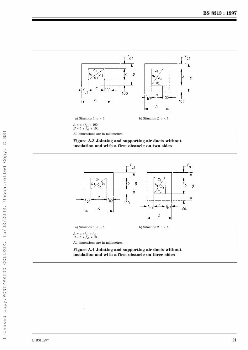
www.bzfxw.com
BSI 1997 21
BS 8313 : 1997
a) Situation 1: a > b b) Situation 2: a < b
A = a +fb1 + 100B = b + fa1 + 100
All dimensions are in millimetres.
Figure A.3 Jointing and supporting air ducts withoutinsulation and with a firm obstacle on two sides
a) Situation 1: a > b b) Situation 2: a < b
A = a +fb1 + fb2B = b + fa1 + 100
All dimensions are in millimetres.
Figure A.4 Jointing and supporting air ducts withoutinsulation and with a firm obstacle on three sides
Licensed copy:PONTYPRIDD COLLEGE, 15/02/2008, Uncontrolled Copy, © BSI
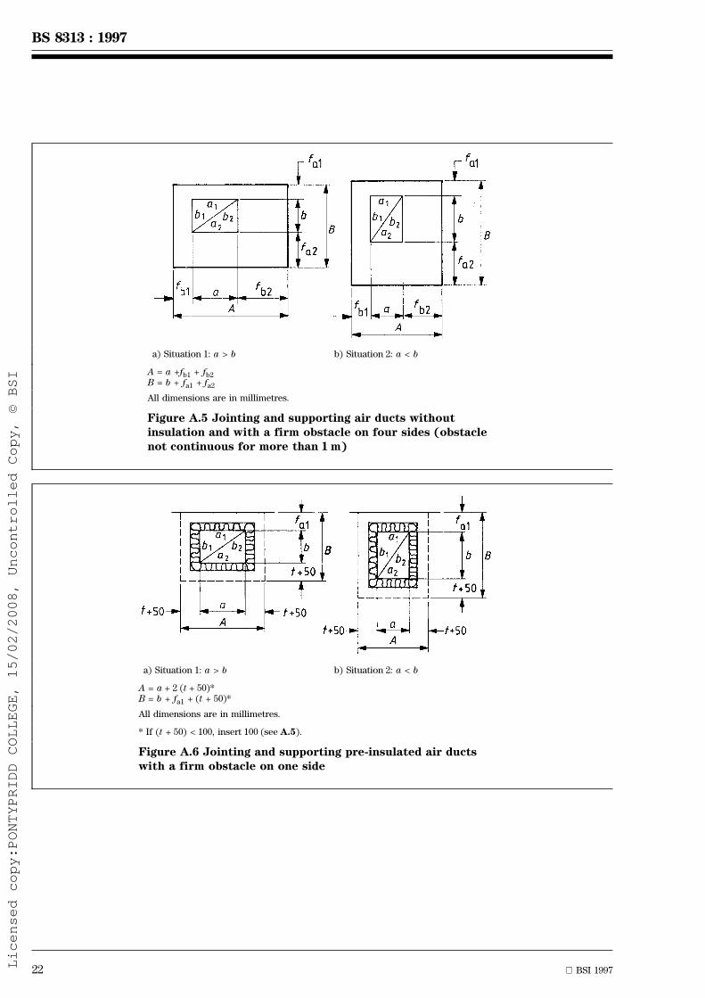
www.bzfxw.com
22 BSI 1997
BS 8313 : 1997
a) Situation 1: a > b b) Situation 2: a < b
A = a +fb1 + fb2B = b + fa1 + fa2
All dimensions are in millimetres.
Figure A.5 Jointing and supporting air ducts withoutinsulation and with a firm obstacle on four sides (obstaclenot continuous for more than 1 m)
a) Situation 1: a > b b) Situation 2: a < b
A = a + 2 (t + 50)*B = b + fa1 + (t + 50)*
All dimensions are in millimetres.
* If (t + 50) < 100, insert 100 (see A.5).
Figure A.6 Jointing and supporting pre-insulated air ductswith a firm obstacle on one side
Licensed copy:PONTYPRIDD COLLEGE, 15/02/2008, Uncontrolled Copy, © BSI
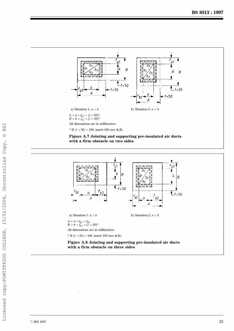
www.bzfxw.com
BSI 1997 23
BS 8313 : 1997
a) Situation 1: a > b b) Situation 2: a < b
A = a + fb1 + (t + 50)*B = b + fa1 + (t + 50)*
All dimensions are in millimetres.
* If (t + 50) < 100, insert 100 (see A.5).
Figure A.7 Jointing and supporting pre-insulated air ductswith a firm obstacle on two sides
a) Situation 1: a > b b) Situation 2: a < b
A = a + fb1 + fb2B = b + fa1 + (t + 50)*
All dimensions are in millimetres.
* If (t + 50) < 100, insert 100 (see A.5).
Figure A.8 Jointing and supporting pre-insulated air ductswith a firm obstacle on three sides
Licensed copy:PONTYPRIDD COLLEGE, 15/02/2008, Uncontrolled Copy, © BSI

www.bzfxw.com
24 BSI 1997
BS 8313 : 1997
a) Situation 1: a > b b) Situation 2: a < b
A = a + fb1 + fb2B = b + fa1 + fa2
All dimensions are in millimetres.
Figure A.9 Jointing and supporting pre-insulated air ductswith a firm obstacle on four sides (obstacle not continuousfor more than 1 m)
a) Situation 1: a > b b) Situation 2: a < b
A = a + 2 (t + 50)*B = b + ea1 + (t + 50)*
All dimensions are in millimetres.
* If (t + 50) < 100, insert 100 (see A.5).
Figure A.10 Insulation of an air duct in position with a firmobstacle on one side
Licensed copy:PONTYPRIDD COLLEGE, 15/02/2008, Uncontrolled Copy, © BSI
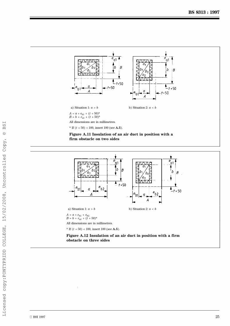
www.bzfxw.com
BSI 1997 25
BS 8313 : 1997
a) Situation 1: a > b b) Situation 2: a < b
A = a + eb1 + (t + 50)*B = b + ea1 + (t + 50)*
All dimensions are in millimetres.
* If (t + 50) < 100, insert 100 (see A.5).
Figure A.11 Insulation of an air duct in position with afirm obstacle on two sides
a) Situation 1: a > b b) Situation 2: a < b
A = a + eb1 + eb2B = b + ea1 + (t + 50)*
All dimensions are in millimetres.
* If (t + 50) < 100, insert 100 (see A.5).
Figure A.12 Insulation of an air duct in position with a firmobstacle on three sides
Licensed copy:PONTYPRIDD COLLEGE, 15/02/2008, Uncontrolled Copy, © BSI

www.bzfxw.com
26 BSI 1997
BS 8313 : 1997
a) Situation 1: a > b b) Situation 2: a < b
A = a + eb1 + eb2B = b + ea1 + ea2
All dimensions are in millimetres.
Figure A.13 Insulation of an air duct in position with a firmobstacle on four sides (obstacle not continuous for morethan 1 m)
f1 = 100 and f2 = 300
All dimensions are in millimetres.
Figure A.14 Examples of installation spaces for flange jointed air ducts
Licensed copy:PONTYPRIDD COLLEGE, 15/02/2008, Uncontrolled Copy, © BSI

www.bzfxw.com
BSI 1997 27
BS 8313 : 1997
Table A.1 Dimensions where f1 = 100 and f2 = 300
a b fb1 fb2 fa1 fa2 A B
< 1 000 < 2 000 f1 b + 200
f1 f1 f1 a + 200
> 1 000 f2 b + 400
a < 1000
100100150200250300400500600
Bb
800100012001400160018002000
3003504004505006007008001000120014001600180020002200
A
150 200 250 300 400 500 600 800 1000
350300 400 450 500 600 700 800 1000 1200
a
��������������������������������
a > 1000
1200100150200250300400500600
b B
800100012001400160018002000
70080090010001200140016001800200022002400
A
1400 1600 1800 2000
1400 1600 1800 2000 2200
a
����������������
All dimensions are in millimetres.
Figure A.15 Installation space dimensions A and B for flange jointed air ductswith a firm obstacle on one side
Licensed copy:PONTYPRIDD COLLEGE, 15/02/2008, Uncontrolled Copy, © BSI
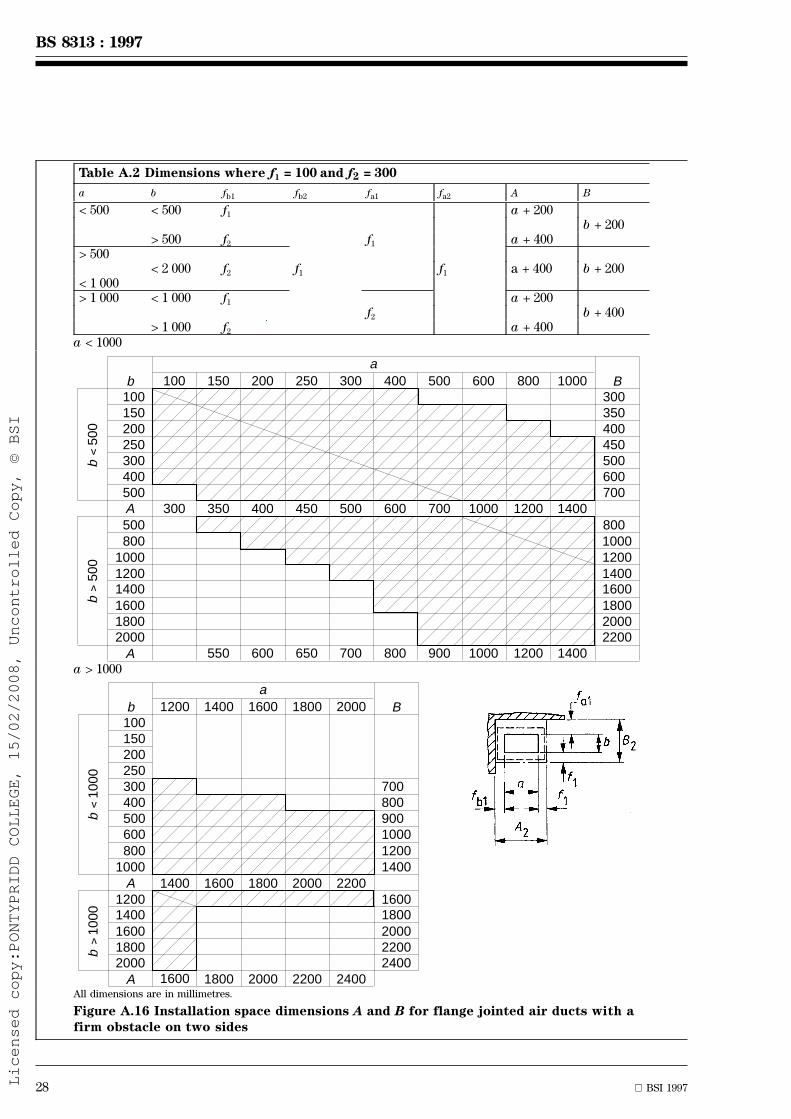
www.bzfxw.com
28 BSI 1997
BS 8313 : 1997
Table A.2 Dimensions where f1 = 100 and f2 = 300
a b fb1 fb2 fa1 fa2 A B
< 500 < 500 f1 a + 200b + 200
> 500 f2 f1 a + 400> 500
< 2 000 f2 f1 f1 a + 400 b + 200< 1 000> 1 000 < 1 000 f1 a + 200
f2 b + 400> 1 000 f2 a + 400
a < 1000
100100150200250300400500A
Bb
500800
100012001400160018002000
300350400450500600700
8001000120014001600180020002200
A
150 200 250 300 400 500 600 800 1000
300 350 400 450 500 600 700 1000 1200 1400
550 600 650 700 800 900 1000 1200 1400
����������������
���������������������
a
b
500
v
b
500
v
a > 1000
1200100150200250300400500600
b B
8001000
A12001400160018002000
700800900100012001400
16001800200022002400
A
1400 1600 1800 2000
1400
1600
1600 1800 2000 2200
1800 2000 2200 2400
a
b
1000
v
b
1000
v
������������
��������
All dimensions are in millimetres.
Figure A.16 Installation space dimensions A and B for flange jointed air ducts with afirm obstacle on two sides
Licensed copy:PONTYPRIDD COLLEGE, 15/02/2008, Uncontrolled Copy, © BSI

www.bzfxw.com
BSI 1997 29
BS 8313 : 1997
Table A.3 Dimensions where f1 = 100 and f2 = 300
a b fb1 fb2 fa1 fa2 A B
< 500 < 500 f1 a + 400b + 200
> 500 f2 f1 a + 600> 500
< 2 000 f2 f2 f1 a + 600 b + 200< 1 000> 1 000 < 1 000 f1 a + 400
f2 b + 400> 1 000 f2 a + 600
a < 1000
100100150200250300400500A
Bb
600800
100012001400160018002000
300350400450500600700
8001000120014001600180020002200
A
150 200 250 300 400 500 600 800 1000
500 550 600 650 700 800 900 1200 1400 1600
750 800 850 900 1000 1100 1200 1400 1600
����������������
���������������������
a
b
500
v
b
500
v
a > 1000
1200100150200250300400500600
b B
8001000
A12001400160018002000
700800900100012001400
16001800200022002400
A
1400 1600 1800 2000
1600
1800
1800 2000 2200 2400
2000 2200 2400 2600
a
b
1000
vb
10
00
v
������������
��������
All dimensions are in millimetres.
Figure A.17 Installation space dimensions A and B for flange jointed air ducts with afirm obstacle on three sides
Licensed copy:PONTYPRIDD COLLEGE, 15/02/2008, Uncontrolled Copy, © BSI
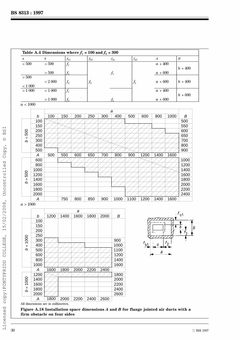
www.bzfxw.com
30 BSI 1997
BS 8313 : 1997
Table A.4 Dimensions where f1 = 100 and f2 = 300
a b fb1 fb2 fa1 fa2 A B
< 500 < 500 f1 a + 400b + 400
> 500 f2 f1 a + 600> 500
< 2 000 f2 f2 f2 a + 600 b + 400< 1 000> 1 000 < 1 000 f1 a + 400
b + 600> 1 000 f2 f2 a + 600
a < 1000
100100150200250300400500A
Bb
600800
100012001400160018002000
500550600650700800900
10001200140016001800200022002400
A
150 200 250 300 400 500 600 800 1000
500 550 600 650 700 800 900 1200 1400 1600
750 800 850 900 1000 1100 1200 1400 1600
������������������������
���������������������
a
b
500
v
b
500
v
a > 1000
1200100150200250300400500600
b B
8001000
A12001400160018002000
90010001100120014001600
18002000220024002600
A
1400 1600 1800 2000
1600
1800
1800 2000 2200 2400
2000 2200 2400 2600
a
b
1000
v
b
1000
v
��������
��������
All dimensions are in millimetres.
Figure A.18 Installation space dimensions A and B for flange jointed air ducts with afirm obstacle on four sides
Licensed copy:PONTYPRIDD COLLEGE, 15/02/2008, Uncontrolled Copy, © BSI

www.bzfxw.com
BSI 1997 31
BS 8313 : 1997
f1 = 100 and f2 = 400
All dimensions are in millimetres.
Figure A.19 Examples of installation spacefor slip jointed air ducts
Table A.5 Values of ea and eb
Dimensions in millimetres
Air duct side aor b
Values of eaand eb
Insulating method(see A.7.4)
1 2 3
Thickness
# 75 > 75 # 75 > 75 # 75 > 75
a # 1000 eb 150 250 150 250 250 300
a > 1000 200 300 400 500 450 500
b # 1000 ea 150 250 150 250 250 300
b > 1000 200 300 400 500 450 500
NOTE. See table A.6.
Table A.6 Values of ea1, ea2, eb1 and eb2 (see figure A.21)
Dimensions in millimetres
ea1 ea, but with a min. of (t + f1) for a # 1000
ea, but with a min. of (t + f2) for a > 1000
eb1 eb, but with a min. of (t + f1) for a # 500 and b # 500 or a > 1000 and b # 1000
eb, but with a min. of (t + f2) for a # 500 and b > 500 or 500 < a # 1000 or a > 1000 and b > 1000
ea2 min. 500
eb2 min. 500
NOTE 1. For the values of ea and eb, see table A.5. f1 = 100 mm and f2 = 300 mm (see figure A.14).
Licensed copy:PONTYPRIDD COLLEGE, 15/02/2008, Uncontrolled Copy, © BSI
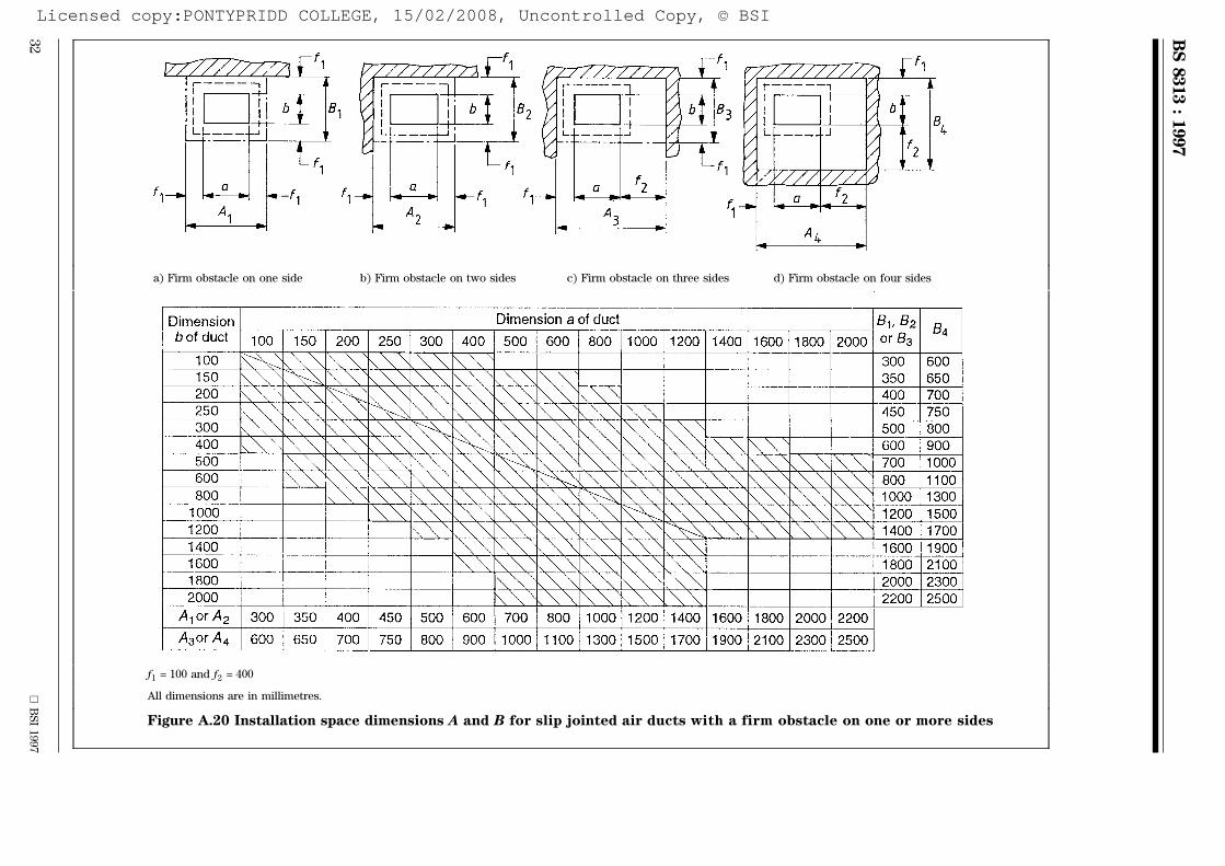
www.bzfxw.com
32
BS
I1997
BS
8313
:1997
a) Firm obstacle on one side b) Firm obstacle on two sides c) Firm obstacle on three sides d) Firm obstacle on four sides
f1 = 100 and f2 = 400
All dimensions are in millimetres.
Figure A.20 Installation space dimensions A and B for slip jointed air ducts with a firm obstacle on one or more sides
Licensed copy:PONTYPRIDD COLLEGE, 15/02/2008, Uncontrolled Copy, © BSI

www.bzfxw.com
BSI 1997 33
BS 8313 : 1997
All dimensions are in millimetres.
Figure A.21 e-values
Table A.7 Values of ea1, ea2, eb1 and eb2 by firm obstacles
Dimensions in millimetres
Firm obstacle on one side Firm obstacle on twosides
Firm obstacle on threesides
Firm obstacle on foursides
ea1 ea, but min. (t +f1) fora # 1000 or min. (t + f2) fora > 1000
ea, but min. (t +f1) for a # 500 or min. (t + f2) for a > 500
ea2 t, but min. 100 t, but min. 100 min. 500
eb1 t, but min. 100 eb, but min. (t +f1) for b # 500 or min. (t +f2) or b > 500
eb2 t, but min. 100 t, but min. 100 min. 500 min. 500
NOTE 1. For the values of ea and eb, see table A.5. f1 = 100 mm and f2 = 300 mm (see figure A.14).
Licensed copy:PONTYPRIDD COLLEGE, 15/02/2008, Uncontrolled Copy, © BSI
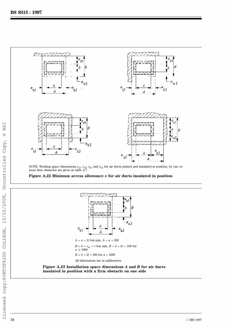
www.bzfxw.com
34 BSI 1997
BS 8313 : 1997
NOTE. Working space dimensions ea1, ea2, eb1 and eb2 for air ducts jointed and insulated in position, by one ormore firm obstacles are given in table A.7.
Figure A.22 Minimum access allowance e for air ducts insulated in position
A = a + 2t but min. A = a + 200
B = b + ea1 + t but min. B = b + 2t + 100 fora # 1000
B = b + 2t + 300 for a > 1000
All dimensions are in millimetres.
Figure A.23 Installation space dimensions A and B for air ductsinsulated in position with a firm obstacle on one side
Licensed copy:PONTYPRIDD COLLEGE, 15/02/2008, Uncontrolled Copy, © BSI

www.bzfxw.com
BSI 1997 35
BS 8313 : 1997
A = a + eb1 +t but min. A = a + 2t + 100 forb # 500
A = a + 2t + 300 for b > 500
B = b + ea1 + t but min. B = b + 2t + 100 fora # 500
B = b + 2t + 300 for a > 500
All dimensions are in millimetres.
Figure A.24 Installation space dimensions A and B for air ductsinsulated in position with a firm obstacle on two sides
A = a + eb1 + 500 but min. A = a + 2t + 550 forb # 500
A = a + 2t + 800 for b > 500
B = b + ea1 + t but min. B = b + 2t + 100 fora # 500
B = b + 2t + 300 for a > 500
All dimensions are in millimetres.
Figure A.25 Installation space dimensions A and B for air ductsinsulated in position with a firm obstacle on three sides
Licensed copy:PONTYPRIDD COLLEGE, 15/02/2008, Uncontrolled Copy, © BSI

www.bzfxw.com
36 BSI 1997
BS 8313 : 1997
A = a + eb1 + 500 but min. A = a + 2t + 600for b # 500
A = a + 2t + 800 for b > 500
B = b + ea1 + 500 but min. B = b + 2t + 600for a # 500
B = b + 2t + 300 for a > 500
All dimensions are in millimetres.
Figure A.26 Installation space dimensions A and B for air ductsinsulated in position with a firm obstacle on four sides
Table A.8. Values of n for a firm obstacle on one side
Dimensions in millimetres
A = a + nn = 2t, but min. 200
Insulationmethod(see A.7.4)
Values of n
t # 75 t > 75
t = 25 t = 50 t = 75 t = 100 t = 125 t = 150
a # 2000 b # 2000 1, 2, 3 200 200 200 200 250 300
B = b + n
n = ea1 + t, but min. 2t, 100(or 300)
a # 1000 b # 2000 1, 2, 3 175 200 230 350 375 400
275 300 325 400 425 450
a > 1000 b # 2000 1, 2, 3 350 400 450 500 550 600
Licensed copy:PONTYPRIDD COLLEGE, 15/02/2008, Uncontrolled Copy, © BSI

www.bzfxw.com
BSI 1997 37
BS 8313 : 1997
Table A.9 Values of n for a firm obstacle on two sides
Dimensions in millimetres
A = a + nn = eb1 + t, but min. 2t + 100 (or 300)
Insulationmethod(see A.7.4)
Values of n
t # 75 t > 75
t = 25 t = 50 t = 75 t = 100 t = 125 t = 150
a # 1000 b # 500 1, 2 175 200 250 350 375 400
3 275 300 325 400 425 450
b > 500 1, 2, 3 350 400 450 500 550 600
a > 1000 b # 500 1 225 250 275 400 425 450
2 425 450 475 600 625 650
3 475 500 525 600 625 650
b > 500 1 350 400 450 500 550 600
2 425 450 475 600 625 650
3 475 500 525 600 625 650
B = b + nn = ea1 + t, but min. 2t + 100 (or 300)
Insulationmethod(see A.7.4)
Values of n
t # 75 t > 75
t = 25 t = 50 t = 75 t = 100 t = 125 t = 150
a # 500 b # 1000 1, 2 175 200 250 350 375 400
3 275 300 325 400 425 450
b > 1000 1, 2, 3 350 400 450 500 550 600
a > 550 b # 1000 1 225 250 275 400 425 450
2 425 450 475 600 625 650
3 475 500 525 600 625 650
b > 1000 1 450 400 450 500 550 600
2 425 450 475 600 625 650
3 475 500 525 600 625 650
Table A.10 Values of n for a firm obstacle on three sides
Dimensions in millimetres
A = a + nn = eb1 + 500, but min. 2t + 600(or 800)
Insulationmethod(see A.7.4)
Values of n
t # 75 t > 75
t = 25 t = 50 t = 75 t = 100 t = 125 t = 150
a # 1000 b # 500 1, 2 650 700 750 800 850 900
3 750 750 750 800 850 900
b > 500 1, 2, 3 850 900 950 1000 1050 1100
a > 1000 b # 500 1 700 700 750 800 850 900
2 900 900 950 1050 1050 1100
3 950 950 950 1050 1050 1100
b > 500 1 850 900 950 1000 1050 1100
2 900 900 950 1050 1050 1100
3 950 950 950 1050 1050 1100
B = b + nn = ea1 + t, but min. 2t + 100 (or 500)
Insulationmethod(see A.7.4)
Values of n
t # 75 t > 75
t = 25 t = 50 t = 75 t = 100 t = 125 t = 150
a # 500 b # 1000 1, 2 175 200 250 350 375 400
3 275 300 325 400 425 450
b > 1000 1, 2, 3 350 400 450 500 550 600
a > 500 b # 1000 1 225 250 275 400 425 450
2 425 450 475 600 625 650
3 475 500 525 600 625 650
b > 1000 1 350 400 450 500 550 600
2 425 450 475 600 625 650
3 475 500 525 600 625 650
Licensed copy:PONTYPRIDD COLLEGE, 15/02/2008, Uncontrolled Copy, © BSI

www.bzfxw.com
38 BSI 1997
BS 8313 : 1997
Table A.11 Values of n for a firm obstacle on four sides
Dimensions in millimetres
A = a + nn = eb1 + 500, but min. 2t + 600(or 800)
Insulationmethod(see A.7.4)
Values of n
t # 75 t > 75
t = 25 t = 50 t = 75 t = 100 t = 125 t = 150
a # 1000 b # 500 1, 2 650 700 750 800 850 900
3 750 750 750 800 850 900
b > 500 1, 2, 3 850 900 950 1000 1050 1100
a > 1000 b # 500 1 700 700 750 800 850 900
2 900 900 950 1050 1050 1100
3 950 950 950 1050 1050 1100
b > 500 1 850 900 950 1000 1050 1100
2 900 900 950 1050 1050 1100
3 950 950 950 1050 1050 1100
B = b + nn = ea1 + 500, but min. 2t + 600(or 800)
Insulationmethod(see A.7.4)
Values of n
t # 75 t > 75
t = 25 t = 50 t = 75 t = 100 t = 125 t = 150
a # 500 b # 1000 1, 2, 650 700 750 800 850 900
3 750 750 750 800 850 900
b > 1000 1, 2, 3 850 900 950 1000 1050 1100
a > 500 b # 1000 1 700 700 750 800 850 900
2 900 900 950 1050 1050 1100
3 950 950 950 1050 1050 1100
b > 1000 1 850 900 950 1000 1050 1100
2 900 900 950 1050 1050 1100
3 950 950 950 1050 1050 1100
Licensed copy:PONTYPRIDD COLLEGE, 15/02/2008, Uncontrolled Copy, © BSI

www.bzfxw.com
BSI 1997 39
BS 8313 : 1997
Annex B (informative)
Installation space for air ducts(simplified method)
B.1 General
This annex differs from annex A in the followingrespects:
a) the method of calculation is greatly simplified;
b) the reference dimension for insulated ducts inthis annex includes the thickness of the insulation;
c) space allowances for insulation fixed to the ductwith adhesive are included.
This annex gives a method for calculating theminimum cross-sectional dimensions of the installationspace necessary for installation and maintenance ofthin walled air ducts (wall thickness notexceeding 15 mm) for ventilation, heating and airconditioning of buildings.
B.2 Field of application
The method is applicable to rectangular and circularair ducts exceeding 100 mm on the smallest sideor 100 mm diameter. It relates only to simple runs ofducts and does not make allowance for fittings such asdampers, bellows, silencers, filters or test points.
The installation spaces of adjacent services are allowedto overlap provided that the necessary clear space ismaintained around each service.
Where the allowances given by this method forinstallation and removal of the air ducts are applied, itis permissible for part of the installation space to beused for other services or building components afterthe air ducts are installed and tested, provided thatthese can be removed if the air duct is to be removed.
The method is not applicable to the design ofinstallation spaces for services other than air ducts.
B.3 Interpretation, exceptions and limitations
B.3.1 The figures referred to in A.6 and A.7 show theinstallation spaces recommended for access to the faceof the air duct shown at the top of the figure. The sizeof the duct is the finished width of this face includingany external insulation but not flanges, cleats or otherjoint components. The hatched area around each figuredenotes the area permitted for firm obstacles whichmay be part of the building or other services. Ademountable casing may be installed in the installationspace.
B.3.2 Provided the appropriate installation spaceexists at all points on either side of the point whereservices penetrate a wall or floor, and there are nojoints or supports to be installed within thispenetration, it is permissible for the dimensions of thepenetration to be less than the installation space. Inthis case, only a minimum clearance around theservices need be provided. In many cases thisclearance should be sealed or fire stopped dependingupon the particular circumstances of the installation.
B.3.3 Where the continuity of a firm obstacle on foursides exceeds 1 m, additional space for safety, drainageand access should be provided.
B.3.4 For circular ducts, the size of the duct shouldbe taken as the diameter.
B.4 Installation spaces for air ducts notinsulated or insulated before installation
Installation spaces for air ducts not insulated orinsulated before installation are shown in figure B.1.
B.5 Installation spaces for air ducts insulatedafter installation
B.5.1 Insulating methods
Typical methods used for insulation after installationare as follows.
a) Method 1. Insulating with rigid slabs, for example,resin bonded mineral wool, fastened by thin steelbands or the like. Without protective covering. (Oneoperation.)
b) Method 2. Insulating with soft, flexible materialssuch as mats of mineral wool, with or withoutnetting reinforcement and metallic facing, wrappedaround the air duct and sewed or clipped inposition. Without protective covering. (Oneoperation.)
c) Method 3. Insulating as methods 1 or 2, but withprotective covering, for example sheet-metal. (Twooperations, first insulating, and then covering.)
d) Method 4. Insulating with rigid or flexiblematerials fixed to the duct by adhesive, with orwithout protective covering. (One or twooperations.)
B.5.2 Installation spaces
Installation spaces for ducts insulated after installationare shown in figure B.2, and table B.1.
For insulating methods 1, 3 and 4, extra space mayneed to be provided if rigid sheets of insulation orcovering more than 400 mm wide are to be used.
Licensed copy:PONTYPRIDD COLLEGE, 15/02/2008, Uncontrolled Copy, © BSI
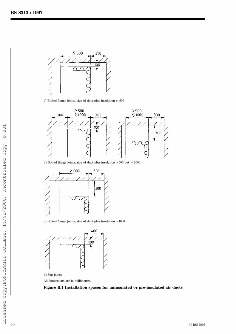
www.bzfxw.com
40 BSI 1997
BS 8313 : 1997
a) Bolted flange joints, size of duct plus insulation # 500
b) Bolted flange joints, size of duct plus insulation > 500 but # 1000
c) Bolted flange joints, size of duct plus insulation > 1000
d) Slip joints
All dimensions are in millimetres.
Figure B.1 Installation spaces for uninsulated or pre-insulated air ducts
Licensed copy:PONTYPRIDD COLLEGE, 15/02/2008, Uncontrolled Copy, © BSI

www.bzfxw.com
BSI 1997 41
BS 8313 : 1997
a) Size of duct plus insulation # 500NOTE. See table B.1 for dimensions of X.
b) Size of duct plus insulation > 500 but # 1000NOTE. See table B.1 for dimensions of X.
c) Size of duct plus insulation > 1000
All dimensions are in millimetres.
Figure B.2 Installation spaces for air ducts insulated after installation
Table B.1Dimensions of X
Insulation method(see B.5.1)
Dimension Xmm
1 125
2 125
3 200
4 200
Licensed copy:PONTYPRIDD COLLEGE, 15/02/2008, Uncontrolled Copy, © BSI

www.bzfxw.com
42 BSI 1997
BS 8313 : 1997
Annex C (informative)
Work in confined spaces
C.1 Work performed in a confined space, such as asmall duct or ceiling void, can subject a worker tophysical and psychological stresses and should beconsidered as potentially hazardous. Such stressesexaggerate medical disabilities. It is advisable to ensurethat workers who have to enter confined spaces aretrained and authorized.
C.2 The atmosphere inside a confined space canpresent a hazard to life due to:
a) oxygen deficiency or enrichment;
b) the presence of flammable gas or vapour;
c) the presence of toxic or corrosive material.
These hazards can be present before entry, e.g. fromleakage of services, or may arise from the work to becarried out, e.g. welding or flame-cutting operations.Before entry into any confined space the potentialhazards should be assessed, and a system of work toensure safety should be devised and applied by acompetent person.
C.3 The atmosphere inside a confined space shouldbe adequately monitored and this will normally involveat least checking oxygen content before entry.Depending on the work being performed it may benecessary to practise periodic monitoring, asappropriate, while it continues.
C.4 Wherever possible, exhaust and/or supplyventilation should be provided to maintain a safeatmosphere of respirable air; systems of work whichrequire workers to wear breathing apparatus shouldnot be used unless provision of adequate ventilation isgenuinely not reasonably practicable. Provision ofadequate ventilation is the only acceptable method fordealing with potentially flammable vapours or oxygenenrichment hazards.
C.5 Because of the peculiar nature of hazardspresented by the atmospheres inside confined spaces,particularly oxygen deficiency and toxic gases, it isessential that workers wear breathing apparatuswhere C.3 cannot be complied with.
Breathing apparatus should be supplied with clean airfrom a source independent of the immediateatmosphere. Irrespective of whether breathingapparatus is worn, persons should never enterflammable or dangerously oxygen enrichedatmospheres.
Annex D (informative)
Acts, bylaws and statutory regulations
D.1 General
The following references relate to the accommodationand maintenance of building services in ducts. The listis not intended to be exhaustive.
D.2 England, Wales and Scotland
Asbestos (Licensing) Regulations, 1983 (SI 1649)
Asbestos (Prohibitions) Regulations, 1992 (SI 3067)
Building Regulations, 1991 (SI 2768)
Building Standards (Scotland) Regulations, 1990(SI 2179)
Construction (Design and Management) Regulations,1994
Construction (General Provisions) Regulations, 1961(SI 1580)
Construction (Working Places) Regulations, 1966(SI 94)
Control of Asbestos at Work Regulations, 1987(SI 2115)
Control of Pollution Act, 1974. Chapter 40
Electricity at Work Regulations, 1989
Electricity (Factories Act) Special Regulations, 1908(SI 1312) and 1944 (SI 739)
Fire Certificates (Special Premises) Regulations, 1976(SI 2003)
Fire Precautions Act, 1971. Chapter 40
Fire Precautions Regulations, 1989 (SI 79)
Fire Precautions (Non-Certificated Factory, Office,Shop and Railway Premises) Regulations, 1989 (SI 78)
Gas Safety Regulations, 1972 (SI 1178)
Gas Safety (Installation and use) Regulations, 1994(SI 1886)
Health and Safety at Work etc. Act, 1974. Chapter 37
Highly Flammable Liquids and Liquefied PetroleumGases Regulations, 1972 (SI 917)
Offices, Shops and Railway Premises Act, 1963.Chapter 41
Petroleum (Consolidation) Act, 1928. Chapter 32
Safety Signs Regulations, 1980 (SI 1471)
Water Bylaws as made by the appropriate waterundertaking authority
Licensed copy:PONTYPRIDD COLLEGE, 15/02/2008, Uncontrolled Copy, © BSI
www.bzfxw.com
BSI 1997 43
BS 8313 : 1997
D.3 Northern Ireland
Asbestos (Prohibition) Regulations (Northern Ireland),1993 (SR 25)
Building Regulations (Northern Ireland), 1994 (SR 243)
Building Regulations (Northern Ireland), Amdt, 1995(SR 473)
Construction (General Provisions) Regulations(Northern Ireland), 1963 (SR 87)
Construction (Working Places) Regulations (NorthernIreland), 1967 (SR 175)
Control of Asbestos at Work Regulations (NorthernIreland), 1988 (SR 74)
Electricity at Work Regulations (Northern Ireland),1991 (SR 13)
Electricity Supply (Northern Ireland) Regulations, 1991(SR 536)
Electricity (Factories Act) Special Regulations(Northern Ireland),1945 (SR 113)
Factories Act (Northern Ireland), 1965. Chapter 20
Gas Safety (Installation and use) Regulations (NorthernIreland), 1995 (SR 3)
Health and Safety at Work (Northern Ireland) Order,1978 (SR 1039 CH 9)
Highly Flammable Liquids and Liquefied PetroleumGases Regulations (Northern Ireland) 1975 (SR 256)
Offices and Shop Premises Act (Northern Ireland),1966. Chapter 26
Petroleum (Consolidation) Act (Northern Ireland),1929. Chapter 13
Pollution Control and Local Government (NorthernIreland) Regulations, 1978 (SR 1049 NI 19)
Safety Signs (Northern Ireland) Regulations, 1981
Water and Sewage Services (Northern Ireland)Regulations, 1993 (SR 3165 NI 6)
Licensed copy:PONTYPRIDD COLLEGE, 15/02/2008, Uncontrolled Copy, © BSI

www.bzfxw.com
blankLicensed copy:PONTYPRIDD COLLEGE, 15/02/2008, Uncontrolled Copy, © BSI
BSI 1997 47
BS 8313 : 1997
List of references (see clause 2)
Normative references
BSI publications
BRITISH STANDARDS INSTITUTION, London
BS 476 : Fire tests on building materials and structuresBS 476 : Part 4 : 1970 Non-combustibility test for materialsBS 476 : Part 24 : 1987 Method for determination of fire resistance of ventilation ducts
BS 1710 : 1984 Specification for identification of pipelines and servicesBS 2830 : 1994 Specification of suspended access equipment (suspended chairs,
traditional steeplejack's seats, work cages, cradles and platforms) for usein the building, engineering construction, steeplejack and cleaningindustries
BS 4211 : 1994 Specification for ladders for permanent access to chimneys, other highstructures, silos and bins
BS 4434 : 1995 Specification for safety and environmental aspects in the design,construction and installation of refrigerating appliances and systems
BS 5266 : Emergency lightingBS 5266 : Part 1 : 1988 Code of practice for the emergency lighting of premises other than
cinemas and other specified premises used for entertainmentBS 5306 : Fire extinguishing installations and equipment on premises
BS 5306 : Part 0 : 1986 Guide for the selection of installed systems and other fire equipmentBS 5378 : Safety signs and colours
BS 5378 : Part 1 : 1980 Specification for colour and designBS 5422 : 1990 Method for specifying thermal insulating materials on pipes, ductwork
and equipment (in the temperature range 240 ÊC to +700 ÊC)BS 5482 : Domestic butane and propane gas burning installations
BS 5482 : Part 1 : 1994 Specification for installations at permanent dwellingsBS 5499 : Fire safety signs, notices and graphic symbols
BS 5499 : Part 1 : 1990 Specification for fire safety signsBS 5499 : Part 2 : 1986 Specification for self-luminous fire safety signsBS 5499 : Part 3 : 1990 Specification for internally-illuminated fire safety signs
BS 5839 : Fire detection and alarm systems for buildingsBS 5839 : Part 1 : 1988 Code of practice for system design, installation and servicing
BS 5845 : 1991 Specification for permanent anchors for industrial safety belts andharnesses
BS 5970 : 1992 Code of practice for thermal insulation of pipework and equipment (intemperature range 2100 ÊC to +870 ÊC)
BS 6100 Glossary of building and civil engineering termsBS 6701 : 1994 Code of practice for installation of apparatus intended for connection to
certain telecommunication systemsBS 6891 : 1988 Specification for installation of low pressure gas pipework of up to 28 mm
(R1) in domestic premises (2nd family gas)BS 7273 : Code of practice for the operation of fire protection measures
BS 7273 : Part 2 : 1992 Mechanical actuation of gaseous total flooding and local applicationextinguishing systems
BS 7671 : 1992 Requirements for electrical installations Ð IEE Wiring Regulations ÐSixteenth edition
BS EN 354 : 1993 Personal protective equipment against falls from a height Ð LanyardsBS EN 358 : 1993 Personal equipment for positioning and prevention of falls Ð Work
positioning systemsBS EN 361 : 1993 Personal protective equipment against falls from a height Ð Full body
harnessesBS EN 365 : 1993 Personal protective equipment against falls from a height Ð General
requirements for instructions for use and for marking
Licensed copy:PONTYPRIDD COLLEGE, 15/02/2008, Uncontrolled Copy, © BSI

BS 8313 : 1997
48 BSI 1997
2) Available from William Culross and Sons Ltd., Coupar Angus, Perthshire PH13 9DF.3) IGE publications are available from the Institution of Gas Engineers, 21 Portland Place, London W1N 3AF.
Other references
[11] Liquefied Petroleum Gas Association Code of Practice No. 22. Coupar Angus: LPGA2), 1996[12] Institution Of Gas Engineers. IGE/UP/2 Gas installation pipework, boosters and compressors on industrialand commercial premises. London: IGE, 19943)
[13] Institution Of Gas Engineers. IGE/TD/4 Edition 3 Gas services. London: IGE, 1994[23] Health & Safety Executive Guidance Note GS 5 Entry into confined spaces. Sudbury: HSE Books, 1995[24]Institution Of Gas Engineers. IGE/SR/5 Entry into and work associated with confined spaces. London:IGE, 1992
Informative references
BSI publications
BRITISH STANDARDS INSTITUTION, London
BS 3974 : Specification for pipe supportsBS 3974 : Part 1 : 1974 Pipe hangers, slider and roller type supportsBS 3974 : Part 2 : 1978 Pipe clamps, cages, cantilevers and attachments to beams
BS 5345 : Code of practice for the selection, installation and maintenance ofelectrical apparatus for use in potentially explosive atmospheres (otherthan mining applications or explosive processing and manufacture)
BS 5345 : Part 1 : 1989 General recommendationsBS 5345 : Part 2 : 1983 Classification of hazardous areas
BS 5429 : 1976 Code of practice for safe operation of small-scale storage facilities forcryogenic liquids
BS 5493 : 1977 Code of practice for protective coating of iron and steel structures againstcorrosion
BS 5572 : 1994 Code of practice for sanitary pipeworkBS 5925 : 1991 Code of practice for ventilation principles and designing for natural
ventilationBS 6213 : 1982 Guide to selection of constructional sealantsBS 6700 : 1987 Specification for design, installation, testing and maintenance of services
supplying water for domestic use within buildings and their curtilagesBS 8210 : 1986 Guide to building maintenance managementBS 8233 : 1987 Code of practice for sound insulation and noise reduction for buildingsBS EN 50014 : 1993 Electrical apparatus for potentially explosive atmospheres Ð General
requirementsCP 102 : 1973 Code of practice for protection of buildings against water from the groundPD 6484 : 1979 Commentary on corrosion at bi-metallic contacts and its alleviation
Licensed copy:PONTYPRIDD COLLEGE, 15/02/2008, Uncontrolled Copy, © BSI
BSI 1997
BS 8313 : 1997
4) HSE Guidance Notes are available from HSE Books, PO Box 1999, Sudbury, Suffolk CO10 6FS.5) Available from NHSS Estates, Room 2E4, 1 Trevelyan Square, Boan Lane, Leeds LS1 6AE.6) Available from the Heating, Ventilating and Air Conditioning Manufacturers' Association, 6 Furlong Road, Bourne End,Buckinghamshire. SL8 5DG.
Other references
[1] GREAT BRITAIN. Approved Document published in connection with B2/B3/B4 of the BuildingRegulations 1991. London: HMSO[2] GREAT BRITAIN. Health and Safety at Work etc. Act 1974. London: HMSO[3] GREAT BRITAIN. Asbestos (Licensing) Regulations 1983. London: HMSO[4] GREAT BRITAIN. Asbestos (Prohibition) Regulations 1992. London: HMSO[5] GREAT BRITAIN. Control of Asbestos at Work Regulations 1987. London: HMSO[6] Health & Safety Executive Guidance Note EH 10 Asbestos Ð exposure limits and measurement of airbornedust concentrations. Sudbury: HSE Books, 19904)
[7] Health & Safety Executive Guidance Note L 27 Control of asbestos at work Ð Approved code of practice.Sudbury: HSE Books, 1993[8] Health & Safety Executive Guidance Note L 28 Work with asbestos insulation, asbestos coating andasbestos insulating board Ð Approved code of practice. Sudbury: HSE Books, 1993[9] GREAT BRITAIN. Gas Safety Regulations 1972. London: HMSO[10] GREAT BRITAIN. Gas Safety (Installation and Use) Regulations 1994. London: HMSO[14] Health & Safety Executive Guidance Note EH 22 Ventilation of the workplace. Sudbury: HSE Books, 1988[15] Health & Safety Executive Guidance Note EH 40/94 Occupational exposure limits. Sudbury: HSEBooks, 1996[16] Department of Health Technical Report HTR 2022 Medical gas pipeline systems Vol. 1-5. Leeds: NHSSEstates5), 1994[17] Department of Health Technical Report HTR 2023 Access and accommodation for engineering servicesVol. 1 & 2. Leeds: NHSS Estates5), 1995[18] Health & Safety Executive Guidance Note EH 54 Assessment of exposure to fume from welding and alliedprocesses. Sudbury: HSE Books, 1990[19] Health & Safety Executive Guidance Note EH 55 The control of exposure to fume from welding, brazingand similar processes. Sudbury: HSE Books, 1990[20] BASEEFA list. 8th edition Certified and approved explosion protected electrical equipment. Sudbury: HSEBooks, 1993[21] Health & Safety Executive Guidance Note GS 16 Gaseous fire extinguishing systems Ð Precautions fortoxic and asphyxiating hazards. Sudbury: HSE Books, 1984[22] Heating And Ventilating Contractors' Association. DW142 Specification for sheet metal ductwork Ð Low,medium and high pressure/velocity air systems. London: Heating and Ventilating Contractors'Association, 1982[25] Health & Safety Executive Guidance Note EH 9 Spraying of highly flammable liquids. Sudbury: HSEBooks, 1977[26] Eurovent Document 2/3 Sheet metal air ducts Ð Standard for dimensions. Bourne End: Heating,Ventilating and Air Conditioning Manufacturers' Association6), 1976
Licensed copy:PONTYPRIDD COLLEGE, 15/02/2008, Uncontrolled Copy, © BSI

BSI389 Chiswick High RoadLondonW4 4AL
|||||||||||||||||||||||||||||||||||||||||||||||||||||||||||||||||||||||||||||||||||||||||||||||||||||||||||||||||||||||||||||||
BSI Ð British Standards Institution
BSI is the independent national body responsible for preparing British Standards. Itpresents the UK view on standards in Europe and at the international level. It isincorporated by Royal Charter.
Revisions
British Standards are updated by amendment or revision. Users of British Standardsshould make sure that they possess the latest amendments or editions.
It is the constant aim of BSI to improve the quality of our products and services. Wewould be grateful if anyone finding an inaccuracy or ambiguity while using thisBritish Standard would inform the Secretary of the technical committee responsible,the identity of which can be found on the inside front cover. Tel: 020 8996 9000.Fax: 020 8996 7400.
BSI offers members an individual updating service called PLUS which ensures thatsubscribers automatically receive the latest editions of standards.
Buying standards
Orders for all BSI, international and foreign standards publications should beaddressed to Customer Services. Tel: 020 8996 9001. Fax: 020 8996 7001.
In response to orders for international standards, it is BSI policy to supply the BSIimplementation of those that have been published as British Standards, unlessotherwise requested.
Information on standards
BSI provides a wide range of information on national, European and internationalstandards through its Library and its Technical Help to Exporters Service. VariousBSI electronic information services are also available which give details on all itsproducts and services. Contact the Information Centre. Tel: 020 8996 7111.Fax: 020 8996 7048.
Subscribing members of BSI are kept up to date with standards developments andreceive substantial discounts on the purchase price of standards. For details ofthese and other benefits contact Membership Administration. Tel: 020 8996 7002.Fax: 020 8996 7001.
Copyright
Copyright subsists in all BSI publications. BSI also holds the copyright, in the UK, ofthe publications of the international standardization bodies. Except as permittedunder the Copyright, Designs and Patents Act 1988 no extract may be reproduced,stored in a retrieval system or transmitted in any form or by any means ± electronic,photocopying, recording or otherwise ± without prior written permission from BSI.
This does not preclude the free use, in the course of implementing the standard, ofnecessary details such as symbols, and size, type or grade designations. If thesedetails are to be used for any other purpose than implementation then the priorwritten permission of BSI must be obtained.
If permission is granted, the terms may include royalty payments or a licensingagreement. Details and advice can be obtained from the Copyright Manager.Tel: 020 8996 7070.
Licensed copy:PONTYPRIDD COLLEGE, 15/02/2008, Uncontrolled Copy, © BSI