Bryce Miller, Alessandra Hruschka, Gina Maliekal Group 11 User Friendly Fastening Device (UF-FD)
31
Bryce Miller, Alessandra Hruschka, Gina Maliekal Group 11 User Friendly Fastening Device (UF-FD)
-
Upload
kendal-burdsall -
Category
Documents
-
view
219 -
download
3
Transcript of Bryce Miller, Alessandra Hruschka, Gina Maliekal Group 11 User Friendly Fastening Device (UF-FD)

Bryce Miller, Alessandra Hruschka, Gina MaliekalGroup 11
User FriendlyFastening Device
(UF-FD)

Review of Project

Design Need
AFOs – promoting proper ambulation cerebral palsy patients donning/doffing – introduction of user error
misalignment of orthotic and foot deviation of treatment; exacerbation of
deformity rigid AFO – body, distal strap, proximal strap proximal strap significant source of user error
patients and/or caretakers

Current Solution
doubled over velcro strap

Design Requirements
compatible with anthropometric parameters of patient’s leg minimum orthotic opening –
3 in. lightweight
mass < 35 ounces ease of donning/doffing
single-handed use minimalistic instruction
product life resistance to wear,
corrosion, component failure
inconspicuous requires actual input
from children patients low maintenance
no special care required
low cost entire AFO <$500
compatible implementation with existing AFO manufacture
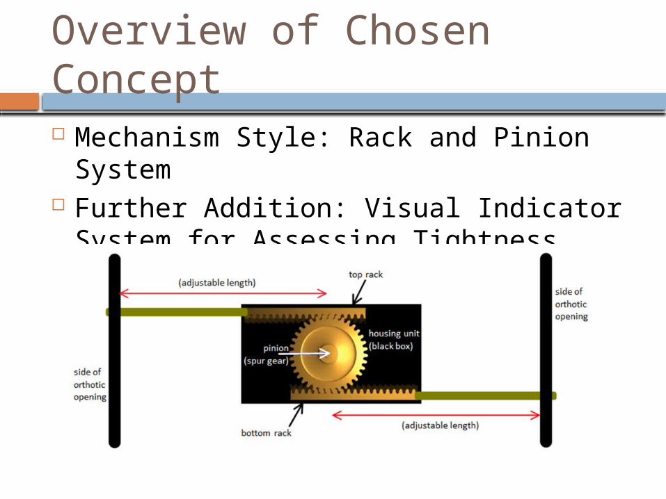
Overview of Chosen Concept Mechanism Style: Rack and Pinion
System Further Addition: Visual Indicator System
for Assessing Tightness

Analytic Efforts

Assessment of Tightening Forces
How tight is “tight enough”? pertinent to the indicator system desired tightening force measure “stored”
within springs initial theoretical approach
compression of springs (Hooke’s Law) equating to the tension in the straps
too many unknowns Normal ForceStrap Tension
Forces
α

Assessment of Tightening Forces (cont’d)
solution: collection of empirical data and selection of specific spring geometry
spring scale with existing strap design with 21 yr old female subject average force from repeated trials was 5.0 lb
four springs; each to be 1.25 lb spring displacement: 0.25 in Hooke’s Law
F = -kx … k = -F/x k = 1.25lb /(.25in) = 5 lb/in

Assessment of Loading Forces What will be peak loading? 45 lb max load – Silva et al failure point material deformation strengths
Silva et al.

Sizing Considerations
anthropometric data of calf circumference minimum two sizes
data of a 5-yr old; focus on CP patients stunted growth and atrophied muscles orthotic opening 1/3 of calf circumference
CP (5 years old) Children: Calf Circumference (cm)
Male Female10% 50% 90% 10% 50% 90%25.9 29.9 35.5 27 30.6 36.5
Data from: http://www.cdc.gov/nchs/data/nhsr/nhsr010.pdf

Specific Details of Chosen Design

Design Overview – The Big Picture
1¾”
3”
1 1/3”

User Interface / Indicator System Shell, Spring Base, Knob Tightening forces spring base into shell Push/pull of knob to lock/unlock

Housing Pieces
Base Cover Plate

Housing Pieces (cont’d)
Shell Indicator Spring Base

Gear Mechanism

Gear Mechanism & Tightening

Locking the Gears
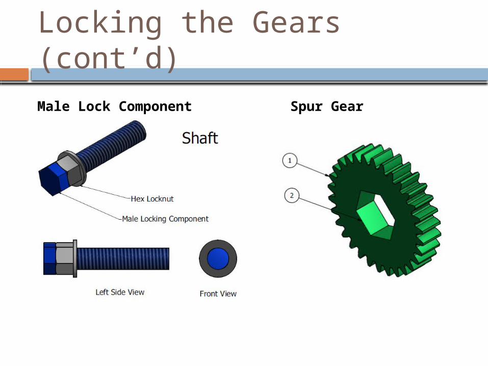
Locking the Gears (cont’d)
Male Lock Component Spur Gear

Summary of Body Components

Manufacture
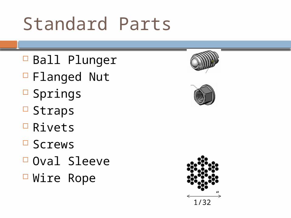
Standard Parts
Ball Plunger Flanged Nut Springs Straps Rivets Screws Oval Sleeve Wire Rope
1/32”

Purchased Parts w/ Modifications Hex Stock
Spur Gear
Racks

Prototyping
Component Cost (Dollars)
Body 148
Cover Plate 122
Knob 60
Lock Ring 110
Racks (x2) 156
Shaft 122
Spring Base 136
Spring Shell 136
Spur Gear 25
Assembly 3.25
Springs 21.80
Locknut 5.11
Ball Plunger 4.23
TOTAL $1050
Total Cost: $1050
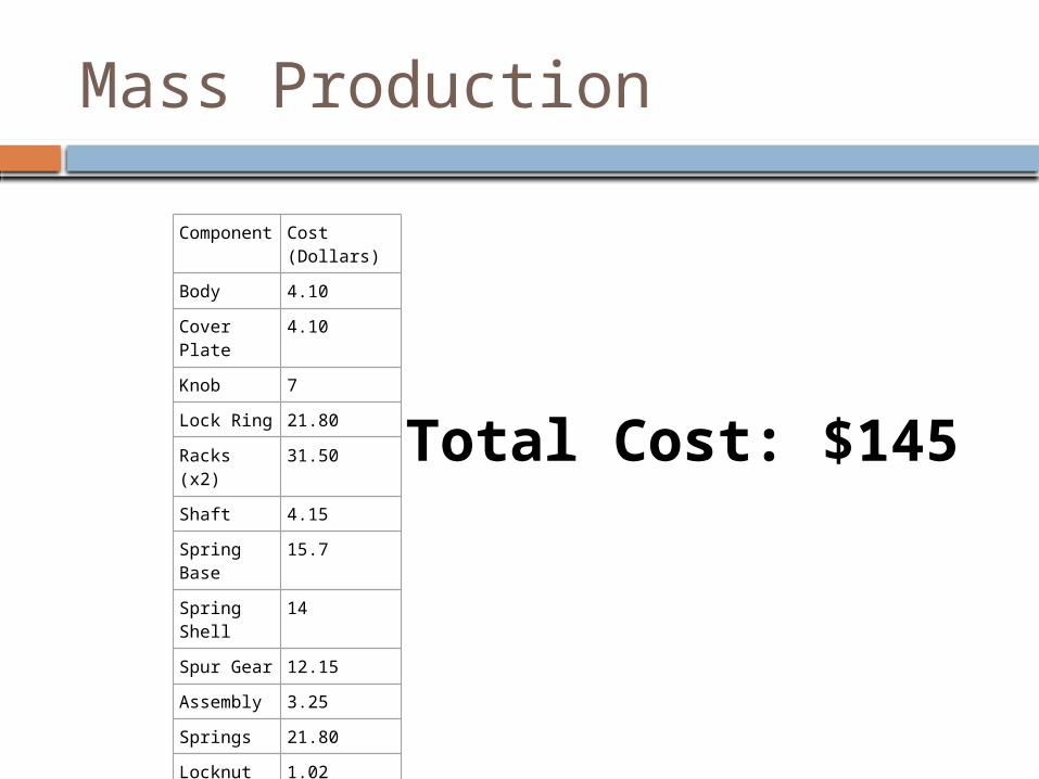
Mass Production
Component Cost (Dollars)
Body 4.10
Cover Plate 4.10
Knob 7
Lock Ring 21.80
Racks (x2) 31.50
Shaft 4.15
Spring Base 15.7
Spring Shell 14
Spur Gear 12.15
Assembly 3.25
Springs 21.80
Locknut 1.02
Ball Plunger 4.23
TOTAL $145
Total Cost: $145

Lead Times
Prototype – 4 weeks
Molds – 12 weeks
1000 Parts – 5weeks
Conclusions

Prospective Conclusions
Further Improvements of Design reduction in cost thinner profile clearer presentation of indicator system
Additional Designs adult size development and incorporation of distal strap
Intellectual Property Considerations possible patents for indicator system and
assembly method undesirable increase in cost to user

Retrospective Conclusions
Did we solve the problem – reducing user error Revising our Project Path
choices made in development of AFO-FD allowing modification of actual manufacture process incorporating more features of the orthotic
Revising our Course Path selection of design topic bioengineering or biotech focus
insufficient preparation for purely mechanical design Semester Trends
compromise and balance of leadership allowance for repeating work and addressing myriad
of small details

What is your name? – Bryce MillerWhat is your group number? – 11
Frequently Asked Questions