
Brute Operator's Manual
89
COMP ACT OM P AC T TM COMP ACT OM P AC T Big Power in Small Places Part No. 999-860.01 Operator’s Manual
-
Upload
richard-wiese -
Category
Documents
-
view
258 -
download
1
Transcript of Brute Operator's Manual

8/6/2019 Brute Operator's Manual
http://slidepdf.com/reader/full/brute-operators-manual 1/88
COMPACTOMPACT
TM
COMPACTOMPACT
Big Power in Small Places
Part No. 999-860.01
Operator’sManual

8/6/2019 Brute Operator's Manual
http://slidepdf.com/reader/full/brute-operators-manual 2/88

8/6/2019 Brute Operator's Manual
http://slidepdf.com/reader/full/brute-operators-manual 3/88
i
Brute Product Warranty
WARRANTY AND LIABILITY LIMITATIONS
Mertz Manufacturing, LLC warrants each new Compact Utility Loader manufactured
(hereinafter referred to as the equipment) by us to be free from defects in materials
and workmanship, for a period of one (1) year or 1000 operational hours, whichever
occurs first from the date of delivery. This warranty is effective provided that the
equipment warranted hereunder is operated by the purchaser in accordance with
generally approved practices, is properly maintained in accordance with the
instructions contained in this owner's manual, and is operated within the
manufacturer's rated capacity limitations.
Any parts of the equipment found to be defective within the warranty period shall be
repaired or replaced, at Mertz Manufacturing, LLC's sole option. Repairs must be
performed at Mertz Manufacturing, LLC facilities or at an authorized dealer facility.
Any part or parts proving defective within the above specified time will be repaired or
replacement parts furnished, F.O.B. Ponca City, Oklahoma, providing such parts are
returned, transportation prepaid, and found to be defective by the manufacturer.
The purchaser is responsible to keep maintenance records to substantiate proper
maintenance. If a defect becomes apparent, it is the purchaser's responsibility to
notify Mertz Manufacturing, LLC or an authorized dealer of said defect. The
purchaser agrees to return the defective equipment or parts to Mertz Manufacturing,LLC or to an authorized dealer facility, freight prepaid, within fifteen (15) days after
the defective condition is discovered.
All warranties, if any, extended to Mertz Manufacturing, LLC by manufacturers and
suppliers of component parts, accessories, or other goods included in the
manufacturing of Mertz Manufacturing, LLC products will be assigned, if
contractually permitted, to the purchaser. Specific component warranty details will be
provided to the purchaser upon request.
This warranty excludes the following: maintenance items including, but not limited
to, seals, track grousers, roller bearings, filters and spark plugs, equipment that has
been repaired, replaced, or altered by someone other than Mertz Manufacturing, LLC
or an authorized service facility without prior approval from Mertz Manufacturing,
LLC unless, however; if Mertz Manufacturing, LLC, in its sole opinion, determines
that the defective condition of the equipment was in no way caused by or was
attributable to said repairs, replacements, or alternatives.
Mertz Manufacturing, LLC and the purchaser agree that, in consideration of the
above expressed warranty, all other warranties other than title, either expressed or
implied, whether arising under law or equity including warranties of merchant ability
and fitness for a particular purpose are excluded from this contract, further, the
foregoing warranty is made solely to the first purchaser and may not be transferred in
any form.
8/6/2019 Brute Operator's Manual
http://slidepdf.com/reader/full/brute-operators-manual 4/88
ii
The sole liability of Mertz Manufacturing, LLC and the exclusive remedy of the
purchaser arising out of the manufacture, sale, or use of the equipment provided
hereunder, on warranties or otherwise, shall be limited to the cost of repair or
replacement of defective parts as herein specified. Further Mertz Manufacturing, LLC's
maximum liability hereunder arising from any cause whatsoever, including but not
limited to, breach of contract or tort (including negligence), shall not exceed the
contract price of the equipment furnished hereunder. Mertz Manufacturing, LLC shall
not be responsible for work done, equipment or parts furnished, or for parts or repairs
made by others unless the work is specifically ordered by Mertz Manufacturing, LLC.
In no event shall Mertz Manufacturing, LLC be liable for removing defective parts or
for reinstalling said parts when repaired or replaced by anyone other than Mertz
Manufacturing, LLC or an authorized service facility or for any costs incurred with such
removal or reinstallation.
CONSEQUENTIAL DAMAGES
Notwithstanding any other provision of this agreement, in no event shall Mertz
Manufacturing, LLC be liable, whether arising under contract, tort (including
negligence) or otherwise, for loss of anticipated profits, loss of use of capital or
revenue, non-operational expenses, increased expense of operation cost of purchased
or replacement equipment, damage to loads or contents of the equipment,
transportation expenses due to repairs, claims of customers, cost of money, or for any
special, incidental or consequential loss or damage of any nature arising at any time
or from any cause whatsoever.This Warranty Agreement shall be governed by, and construed and enforced in
accordance with the laws of the State of Oklahoma. Any litigation under this warranty
will be held in Kay County in accordance with the laws of Oklahoma.
Mertz Manufacturing, LLC P.O. Box 150 Ponca City, OK 74602
PO BOX 150 (74602) / 1701 N WAVERLY / PONCA CITY, OK 74601
PHONE: (580) 762-5646 / FAX: (580) 767-8411 / NT FAX: (580) 765-3934
www.boxerok.com
8/6/2019 Brute Operator's Manual
http://slidepdf.com/reader/full/brute-operators-manual 5/88
iii
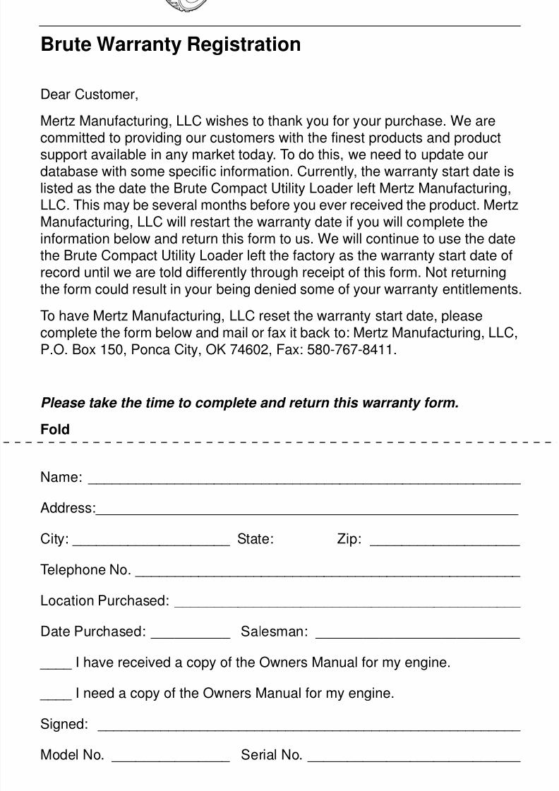
Brute Warranty Registration
Dear Customer,
Mertz Manufacturing, LLC wishes to thank you for your purchase. We are
committed to providing our customers with the finest products and productsupport available in any market today. To do this, we need to update ourdatabase with some specific information. Currently, the warranty start date islisted as the date the Brute Compact Utility Loader left Mertz Manufacturing,LLC. This may be several months before you ever received the product. MertzManufacturing, LLC will restart the warranty date if you will complete theinformation below and return this form to us. We will continue to use the datethe Brute Compact Utility Loader left the factory as the warranty start date of
record until we are told differently through receipt of this form. Not returningthe form could result in your being denied some of your warranty entitlements.
To have Mertz Manufacturing, LLC reset the warranty start date, pleasecomplete the form below and mail or fax it back to: Mertz Manufacturing, LLC,P.O. Box 150, Ponca City, OK 74602, Fax: 580-767-8411.
Please take the time to complete and return this warranty form.
Fold
Name: _______________________________________________________
Address:______________________________________________________
City: ____________________ State: Zip: ___________________
Telephone No. _________________________________________________
Location Purchased: ____________________________________________
Date Purchased: __________ Salesman: __________________________
____ I have received a copy of the Owners Manual for my engine.
____ I need a copy of the Owners Manual for my engine.
Signed: ______________________________________________________
Model No. _______________ Serial No. ___________________________

8/6/2019 Brute Operator's Manual
http://slidepdf.com/reader/full/brute-operators-manual 6/88
iv
Mertz Manufacturing, LLC
P.O. Box 150
Ponca City, OK 74602
Affix
Stamp
Here
8/6/2019 Brute Operator's Manual
http://slidepdf.com/reader/full/brute-operators-manual 7/88
v
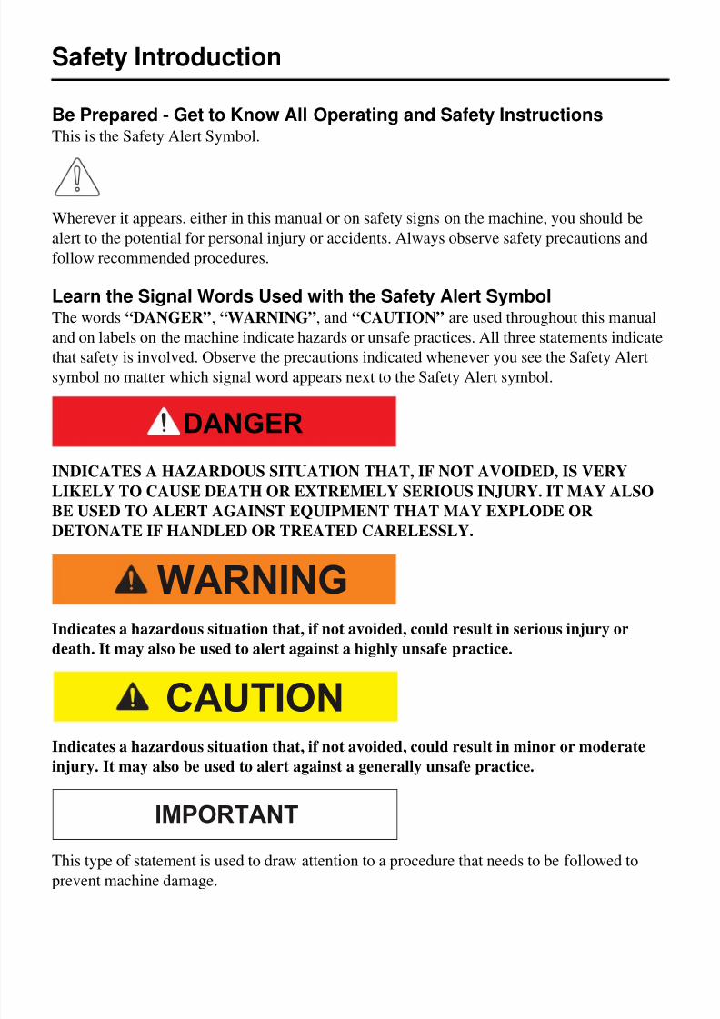
Safety Introduction
Be Prepared - Get to Know All Operating and Safety InstructionsThis is the Safety Alert Symbol.
Wherever it appears, either in this manual or on safety signs on the machine, you should be
alert to the potential for personal injury or accidents. Always observe safety precautions and
follow recommended procedures.
Learn the Signal Words Used with the Safety Alert SymbolThe words “DANGER”, “WARNING”, and “CAUTION” are used throughout this manual
and on labels on the machine indicate hazards or unsafe practices. All three statements indicate
that safety is involved. Observe the precautions indicated whenever you see the Safety Alertsymbol no matter which signal word appears next to the Safety Alert symbol.
INDICATES A HAZARDOUS SITUATION THAT, IF NOT AVOIDED, IS VERY
LIKELY TO CAUSE DEATH OR EXTREMELY SERIOUS INJURY. IT MAY ALSO
BE USED TO ALERT AGAINST EQUIPMENT THAT MAY EXPLODE OR
DETONATE IF HANDLED OR TREATED CARELESSLY.
Indicates a hazardous situation that, if not avoided, could result in serious injury or
death. It may also be used to alert against a highly unsafe practice.
Indicates a hazardous situation that, if not avoided, could result in minor or moderate
injury. It may also be used to alert against a generally unsafe practice.
This type of statement is used to draw attention to a procedure that needs to be followed to
prevent machine damage.
DANGER
WARNING
CAUTION
IMPORTANT

8/6/2019 Brute Operator's Manual
http://slidepdf.com/reader/full/brute-operators-manual 8/88
vi
8/6/2019 Brute Operator's Manual
http://slidepdf.com/reader/full/brute-operators-manual 9/88
vii
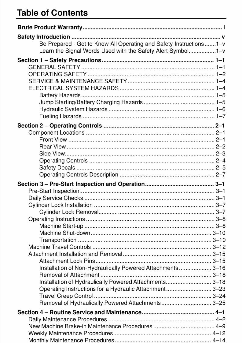
Table of Contents
Brute Product Warranty....................................................................................... i
Safety Introduction ............................................................................................. v
Be Prepared - Get to Know All Operating and Safety Instructions .......1–v
Learn the Signal Words Used with the Safety Alert Symbol.................1–v
Section 1 – Safety Precautions...................................................................... 1–1GENERAL SAFETY ................................................................................... 1–1
OPERATING SAFETY ............................................................................... 1–2
SERVICE & MAINTENANCE SAFETY...................................................... 1–4
ELECTRICAL SYSTEM HAZARDS ........................................................... 1–4
Battery Hazards................................................................................... 1–5
Jump Starting/Battery Charging Hazards ............................................ 1–5
Hydraulic System Hazards .................................................................. 1–6
Fueling Hazards .................................................................................. 1–7
Section 2 – Operating Controls ..................................................................... 2–1
Component Locations ................................................................................ 2–1
Front View ........................................................................................... 2–1
Rear View ............................................................................................ 2–2
Side View............................................................................................. 2–3
Operating Controls .............................................................................. 2–4
Safety Decals ...................................................................................... 2–5
Operating Controls Description ........................................................... 2–7
Section 3 – Pre-Start Inspection and Operation........................................... 3–1
Pre-Start Inspection.................................................................................... 3–1
Daily Service Checks ................................................................................. 3–1
Cylinder Lock Installation ........................................................................... 3–7
Cylinder Lock Removal........................................................................ 3–7
Operating Instructions ................................................................................ 3–8
Machine Start-up ................................................................................. 3–8
Machine Shut-down........................................................................... 3–10
Transportation ................................................................................... 3–10Machine Travel Controls .......................................................................... 3–12
Attachment Installation and Removal ....................................................... 3–15
Attachment Lock Pins........................................................................ 3–15
Installation of Non-Hydraulically Powered Attachments .................... 3–16
Removal of Attachment ..................................................................... 3–18
Installation of Hydraulically Powered Attachments............................ 3–18
Operating Instructions for a Hydraulic Attachment............................ 3–23
Travel Creep Control ......................................................................... 3–24
Removal of Hydraulically Powered Attachments............................... 3–25
Section 4 – Routine Service and Maintenance............................................. 4–1
Daily Maintenance Procedures .................................................................. 4–2
New Machine Brake-in Maintenance Procedures ...................................... 4–9
Weekly Maintenance Procedures............................................................. 4–12
Monthly Maintenance Procedures............................................................ 4–14
Annual Maintenance Procedures ............................................................. 4–18

8/6/2019 Brute Operator's Manual
http://slidepdf.com/reader/full/brute-operators-manual 10/88
viii
General Maintenance ............................................................................... 4–20
Draining Fuel Tank (Gasoline)........................................................... 4–20
Section 5 – Troubleshooting.......................................................................... 5–1
Engine Troubleshooting**........................................................................... 5–4
Section 6 – General Specifications ............................................................... 6–1
Wheel Unit .................................................................................................. 6–1Track Unit ................................................................................................... 6–1
Vibration Testing ........................................................................................ 6–2
Brute 427TRX...................................................................................... 6–2
Brute 427W.......................................................................................... 6–2
Noise Testing ............................................................................................. 6–2
Brute 427TRX...................................................................................... 6–2
Brute 427W.......................................................................................... 6–2
8/6/2019 Brute Operator's Manual
http://slidepdf.com/reader/full/brute-operators-manual 11/88
1-1
Section 1 – Safety Precautions
Since Mertz Manufacturing has no direct control over machine application or operation,
following the proper safety practices is the responsibility of the owner and/or
operator.Remember that this unit is only as safe as those who operate it. Safety tips shown
throughout this Operator's Manual must be followed at all times.
GENERAL SAFETY
• Never operate the Brute without first completely reading and understanding this Owner’s
Manual.
• Only authorized, qualified, and trained personnel are allowed to operate this machine.
• Never operate the machine under the influence of alcohol, awareness altering drugs, or
medications that would affect your ability to operate safely.
• KEEP CHILDREN CLEAR FROM THE WORK SITE AREA AT ALL TIMES!
• NEVER ALLOW A CHILD TO OPERATE OR RIDE ON THE MACHINE
• Serious injury or death involving children can occur. Stay ALERT and be aware of your
surroundings at all times. Stop operations if children wander onto the job site. Resume work
only when the operating area is clear.
• Keep all non-operating personnel away from the machine during operation.
• Passengers must never be allowed to ride on the machine or any attachment.
• Wearing protective clothing and gear, such as hard hats, safety glasses, safety shoes, hearing
protection, breathing protection, and long pants and shirts is highly recommended. Do not
operate in clothing or shoes which will expose skin or feet to possible flying debris.• Clothing should be relatively close fitting. Loose clothing, rings, and other jewelry should be
avoided because of the danger of catching them on machine parts or controls or on any
rotating parts, either on the machine or any attachment.
• Keep hands/fingers clear from all rotating parts.
• Never touch engine parts or machine components while they are hot.
• Always perform the “Standard Shut Down Procedure” shown in this manual, if the unit will
be left unattended for any length of time.
• Use only original CPI or approved replacement parts and attachments. Imitation parts may
lead to unit damage and/or injury to personnel. The machines’ warranty may be voided if unauthorized parts and attachments are used.
8/6/2019 Brute Operator's Manual
http://slidepdf.com/reader/full/brute-operators-manual 12/88
1-2
Safety Precautions
OPERATING SAFETY
• Plan ahead and learn as much as possible about your job-site area before beginning any
work.
• Know the exact location of overhead power lines or obstructions.
• Have all buried lines such as; gas, electric, water, telephone and cable TV, marked by the
proper authorities.
• Prior to use, perform the “Pre-Start Inspection” and Daily Maintenance to make sure that the
unit is in safe operating condition.
• Never operate a malfunctioning unit!
• Keep hands, gloves, shoes, control knobs, and operator platform clean. Slippery controls can
cause you to lose control, which may result in an accident.
• Always keep a firm grip on the hand rails located at the operator's platform during travel and
operations to prevent falling off the unit.
• When working on an unfamiliar construction site, review, understand and follow job site
safety rules.• Keep the work site clear of all non-operating personnel. Should a person enter the work area,
stop machine operation until the work area is clear.
• Prior to unloading the unit and starting to work, inspect the path you will travel and work site
area for potential hazards. Some of the hazardous conditions you may encounter are:
– Holes
– Deep ditches or excavations
– Drop-offs
– Soft un-compacted soil
– Culverts– Deep mud / Standing Water
– Large rocks
– Slippery surfaces
– Steep slopes
– Tall grass, trees, or shrubs
If any of these conditions exist, correct the hazard or obstruction. If any of these conditions
can not be corrected, avoid operating or traveling near them.
• Be extremely cautious traveling through or near trees, brush, shrubs or any obstacles which
might obscure your vision. These might hide potential hazards, such as the edge of a steep
slope, deep holes, large rocks, etc.
• Never operate near a ditch or embankment where loose or soft ground conditions could cause
the surface to give way under the machine causing it to become unstable.
• Never exceed the rated capacity of the machine. When using attachments, know their
capacity ratings and unit limitations. Unit specifications can be found in the Operator's
Manual
8/6/2019 Brute Operator's Manual
http://slidepdf.com/reader/full/brute-operators-manual 13/88
1-3
Safety Precautions
• Never attempt to operate any attachment without first understanding proper installation and
operating procedures. The center of gravity, stability, and operating characteristics of the
entire machine will change with the use of different attachments.
• Operate all controls slowly and smoothly and never abruptly stop any function. This can
cause the machine to become unstable.
• Always look in the direction of travel.
• Come to a complete stop prior to reversing travel directions.• Reduce speed and proceed with caution when traveling in reverse or turning.
• Never travel with the loader boom or attachment raised. Lower the boom or attachment as
soon as possible and travel with the boom at the lowest safe height.
• When traveling with a loaded bucket or forks, the load should be level and the bucket or
forks tilted back to reduce spilling or loosing the load.
• Approach corners slowly, turning too fast or sharp may cause the machine to tip over.
• Stay alert when operating near traffic or roadways.
• If the unit should begin to tip or become unstable, DO NOT try to stabilize the unit with yourlegs or arms.
• If the unit is involved in an accident or inadvertently damaged during operation, stop and
perform a thorough inspection. Make sure the unit is in safe operating condition prior to
resuming work.
• Be alert to any unusual reaction to any of the controls. If anything unusual is noticed, shut the
machine down and thoroughly inspect it to determine the cause of the problem. Do not
operate the machine until all required repairs have been made.
• If the unit must be left unattended, shut the machine down and make sure that it can not be
started by an unauthorized individual.• Operating on steep slopes can be dangerous and there is a greater risk of the machine tipping
over or becoming unstable. The list of rules below must be understood and followed for
maximum safety:
– Avoid excessively steep slopes or unstable surfaces. If travel on a slope is necessary, keep
the load low and proceed with extreme caution.
– DO NOT travel ACROSS excessively steep slopes under any circumstances.
– Travel straight up and down slopes with the heavy end of the machine pointing up the
incline. When the machine has no load, the operator's platform end of the machine is
considered the heavy end. When the machine is loaded or has an attachment on the frontof the machine, the front is considered the heavy end.
– Turning on slopes is not a recommended practice, however if you must turn on slopes;
reduce travel speed to as slow as possible, and exercise extreme caution. Avoid sharp turns
or sudden movements.
– Wet or slick ground conditions should be avoided as reduced traction could cause the
machine to slide down the slope.
– Do not attempt to install or remove attachments on a slope.
– Never park the unit on a slope
8/6/2019 Brute Operator's Manual
http://slidepdf.com/reader/full/brute-operators-manual 14/88
1-4
Safety Precautions
SERVICE & MAINTENANCE SAFETY
Maintenance work can be hazardous if not done in a careful manner. All personnel should
realize the hazards and strictly follow safe maintenance practices. Failure to comply with these
safety precautions may result in serious personal injury and/or death.
• Use only CPI supplied or approved replacement parts and attachments.Imitation parts may
lead to unit damage and/or injury to personnel. Warranty may be voided if unauthorized parts
and attachments are used.
• Wear the proper protective clothing and personal safety equipment necessary to perform the
maintenance or service required.
• Keep the machine free of grass, leaves, or other debris build-up.
• Clean up oil or fuel spillage.
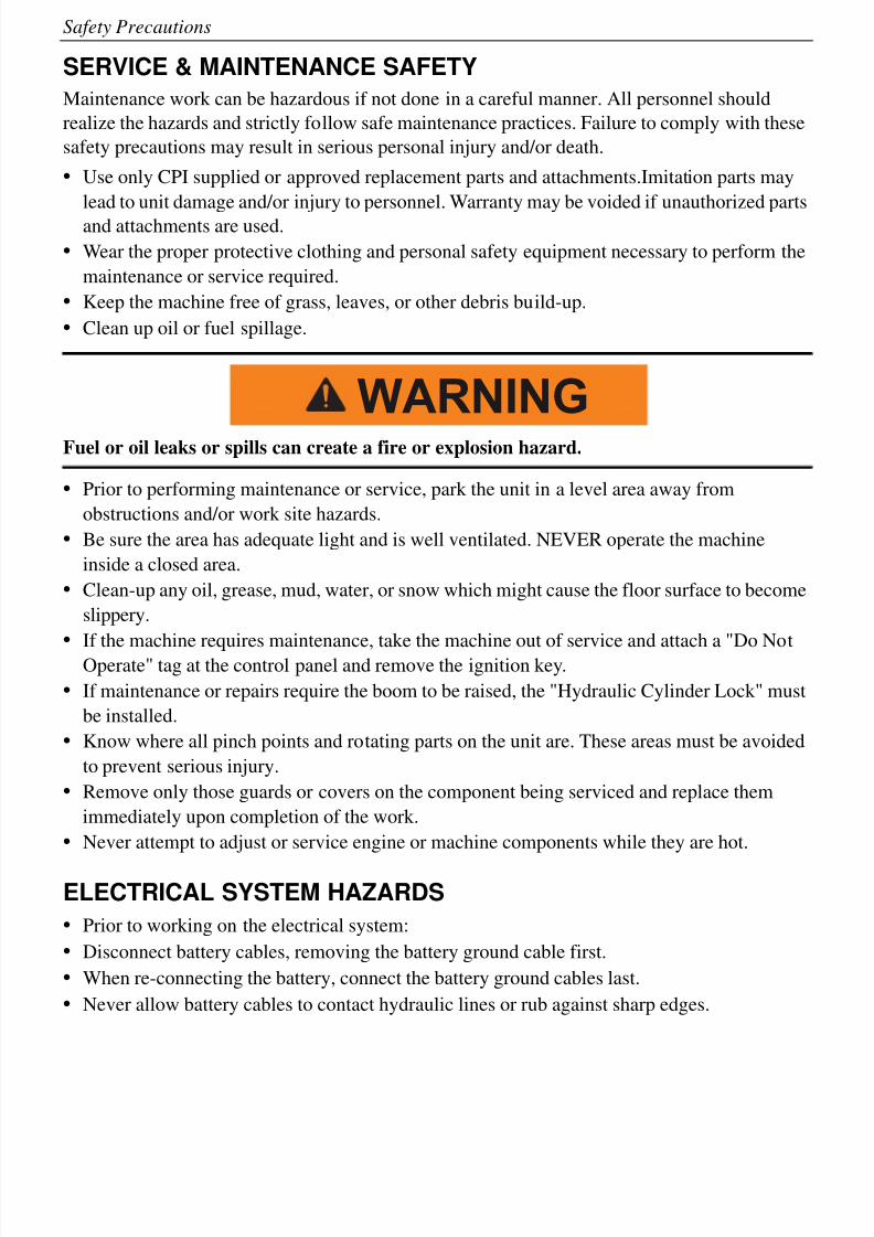
Fuel or oil leaks or spills can create a fire or explosion hazard.
• Prior to performing maintenance or service, park the unit in a level area away from
obstructions and/or work site hazards.
• Be sure the area has adequate light and is well ventilated. NEVER operate the machine
inside a closed area.
• Clean-up any oil, grease, mud, water, or snow which might cause the floor surface to become
slippery.
• If the machine requires maintenance, take the machine out of service and attach a "Do NotOperate" tag at the control panel and remove the ignition key.
• If maintenance or repairs require the boom to be raised, the "Hydraulic Cylinder Lock" must
be installed.
• Know where all pinch points and rotating parts on the unit are. These areas must be avoided
to prevent serious injury.
• Remove only those guards or covers on the component being serviced and replace them
immediately upon completion of the work.
• Never attempt to adjust or service engine or machine components while they are hot.
ELECTRICAL SYSTEM HAZARDS
• Prior to working on the electrical system:
• Disconnect battery cables, removing the battery ground cable first.
• When re-connecting the battery, connect the battery ground cables last.
• Never allow battery cables to contact hydraulic lines or rub against sharp edges.
WARNING
8/6/2019 Brute Operator's Manual
http://slidepdf.com/reader/full/brute-operators-manual 15/88
1-5
Safety Precautions
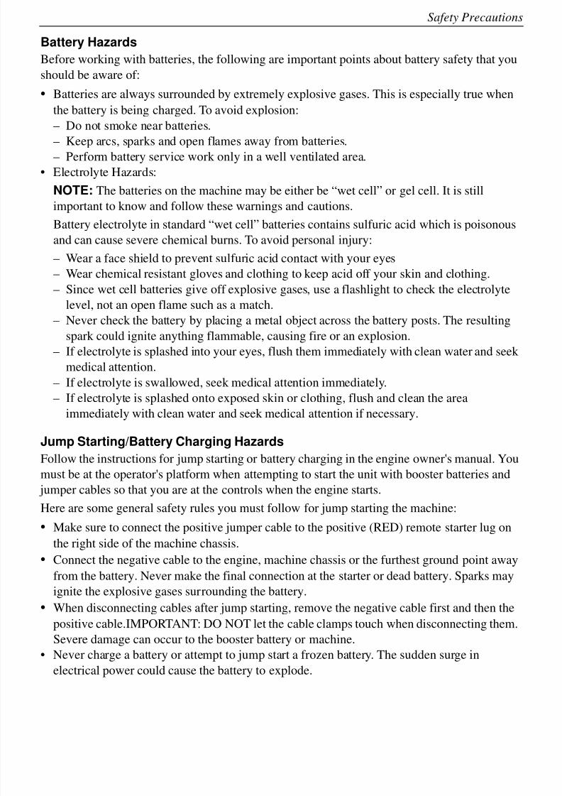
Battery Hazards
Before working with batteries, the following are important points about battery safety that you
should be aware of:
• Batteries are always surrounded by extremely explosive gases. This is especially true when
the battery is being charged. To avoid explosion:
– Do not smoke near batteries.
– Keep arcs, sparks and open flames away from batteries.– Perform battery service work only in a well ventilated area.
• Electrolyte Hazards:
NOTE: The batteries on the machine may be either be “wet cell” or gel cell. It is still
important to know and follow these warnings and cautions.
Battery electrolyte in standard “wet cell” batteries contains sulfuric acid which is poisonous
and can cause severe chemical burns. To avoid personal injury:
– Wear a face shield to prevent sulfuric acid contact with your eyes
– Wear chemical resistant gloves and clothing to keep acid off your skin and clothing.– Since wet cell batteries give off explosive gases, use a flashlight to check the electrolyte
level, not an open flame such as a match.
– Never check the battery by placing a metal object across the battery posts. The resulting
spark could ignite anything flammable, causing fire or an explosion.
– If electrolyte is splashed into your eyes, flush them immediately with clean water and seek
medical attention.
– If electrolyte is swallowed, seek medical attention immediately.
– If electrolyte is splashed onto exposed skin or clothing, flush and clean the area
immediately with clean water and seek medical attention if necessary.
Jump Starting/Battery Charging Hazards
Follow the instructions for jump starting or battery charging in the engine owner's manual. You
must be at the operator's platform when attempting to start the unit with booster batteries and
jumper cables so that you are at the controls when the engine starts.
Here are some general safety rules you must follow for jump starting the machine:
• Make sure to connect the positive jumper cable to the positive (RED) remote starter lug on
the right side of the machine chassis.
• Connect the negative cable to the engine, machine chassis or the furthest ground point awayfrom the battery. Never make the final connection at the starter or dead battery. Sparks may
ignite the explosive gases surrounding the battery.
• When disconnecting cables after jump starting, remove the negative cable first and then the
positive cable.IMPORTANT: DO NOT let the cable clamps touch when disconnecting them.
Severe damage can occur to the booster battery or machine.
• Never charge a battery or attempt to jump start a frozen battery. The sudden surge in
electrical power could cause the battery to explode.
8/6/2019 Brute Operator's Manual
http://slidepdf.com/reader/full/brute-operators-manual 16/88
1-6
Safety Precautions
Hydraulic System Hazards
The hydraulic system is under pressure whenever the engine is running and may hold pressure
even after the engine is shut off. Cycle all hydraulic controls after the loader boom is resting on
the ground. Some components will retain residual or trapped pressure. Use extreme caution
when removing any hydraulic component.
During inspection of the hydraulic system:
• Cycle all hydraulic controls to release residual pressure.
• Wait for the hydraulic fluid to cool down before disconnecting any hydraulic lines. Hot
hydraulic fluid can cause severe burns.
Hydraulic oil under pressure can penetrate body tissue causing serious injury and
possible death. When troubleshooting a hydraulic system for leaks, always use cardboard
or wood as a detector. DO NOT USE YOUR BARE HANDS. If you are injected with
hydraulic oil or any other fluids, immediately seek treatment by a doctor trained in the
treatment of penetrating fluid injuries.
• Hydraulic fluid can cause permanent eye injury. Wear safety glasses or a full face shield to
provide appropriate eye protection.
• When venting or filling the hydraulic system, loosen the filler cap slowly to allow any
pressure in the hydraulic tank to be released and remove the cap gradually.
WARNING
8/6/2019 Brute Operator's Manual
http://slidepdf.com/reader/full/brute-operators-manual 17/88
1-7
Safety Precautions
Fueling Hazards
Most fuels are highly flammable. Observe the following precautionary practices to reduce the
possibility of a serious accident:
• Always refuel the unit in an open, well ventilated area away from sparks or open flames.
Gasoline Engines:
• Shut the engine off before attempting to fuel the machine. Never refuel a unit while
it is running.
• Allow engine to cool before re-fueling
• Always use a funnel or pour spout when filling the tanks.
• Gasoline is extremely flammable and highly explosive, when fueling. Under certain
circumstances a static charge can develop and ignite the gasoline. Make sure thatyou are standing on the ground when filling the gas tanks.
• If you are filling the gas tanks from a service vehicle, make sure to connect the
service vehicles ground cable to the machine before beginning the fueling process
and keep the fuel nozzle in constant contact with the rim of the machines fuel tank.
• To avoid static sparks when using a portable fuel container, keep the fuel container
nozzle in contact with the tank opening during filling.
• Make sure to move the unit from the transport truck or trailer and only refuel the
unit on the ground, using an approved container.
• When filling a portable gas container, always place it on the ground. Never fill aportable gas container while it is inside a vehicle, truck, pick-up bed, or any
surface.
• Keep sparks and flames away from fuel.
• Due to the potential for static discharge, do not use any handheld electronic
devices, i.e. cell phones, etc. while fueling the machine.
• Do not smoke while refueling or when handling the fuel container.
• Never cut or weld on or near fuel lines, tanks or containers.
• Never overfill the tank.
• Clean up spilled fuel immediately.• Store fuel in an approved container and keep out of the reach of children.
DANGER

8/6/2019 Brute Operator's Manual
http://slidepdf.com/reader/full/brute-operators-manual 18/88
1-8
Safety Precautions
8/6/2019 Brute Operator's Manual
http://slidepdf.com/reader/full/brute-operators-manual 19/88
2-1
Section 2 – Operating Controls
Component Locations
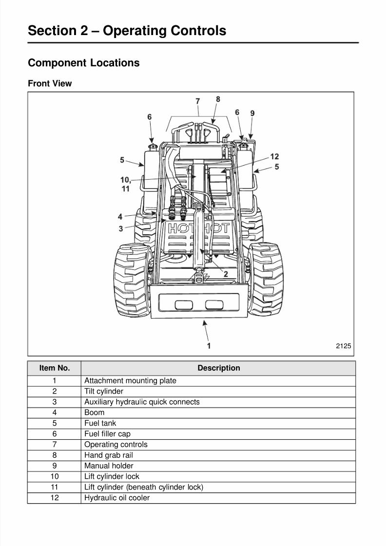
Front View
Item No. Description
1 Attachment mounting plate2 Tilt cylinder
3 Auxiliary hydraulic quick connects
4 Boom
5 Fuel tank
6 Fuel filler cap
7 Operating controls
8 Hand grab rail
9 Manual holder
10 Lift cylinder lock11 Lift cylinder (beneath cylinder lock)
12 Hydraulic oil cooler
2125
8/6/2019 Brute Operator's Manual
http://slidepdf.com/reader/full/brute-operators-manual 20/88
2-2
Operating Controls
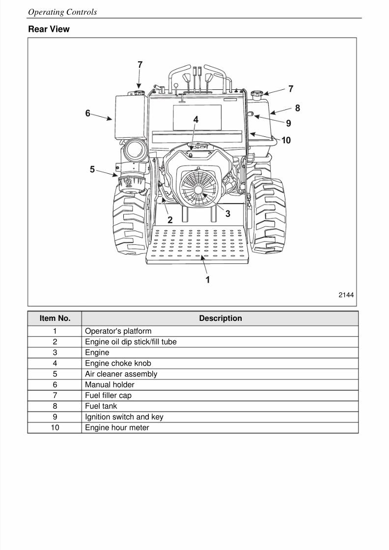
Rear View
Item No. Description
1 Operator's platform
2 Engine oil dip stick/fill tube
3 Engine
4 Engine choke knob
5 Air cleaner assembly
6 Manual holder7 Fuel filler cap
8 Fuel tank
9 Ignition switch and key
10 Engine hour meter
8
7
7
6
3
5
2
49
1
10
2144
8/6/2019 Brute Operator's Manual
http://slidepdf.com/reader/full/brute-operators-manual 21/88
2-3
Operating Controls
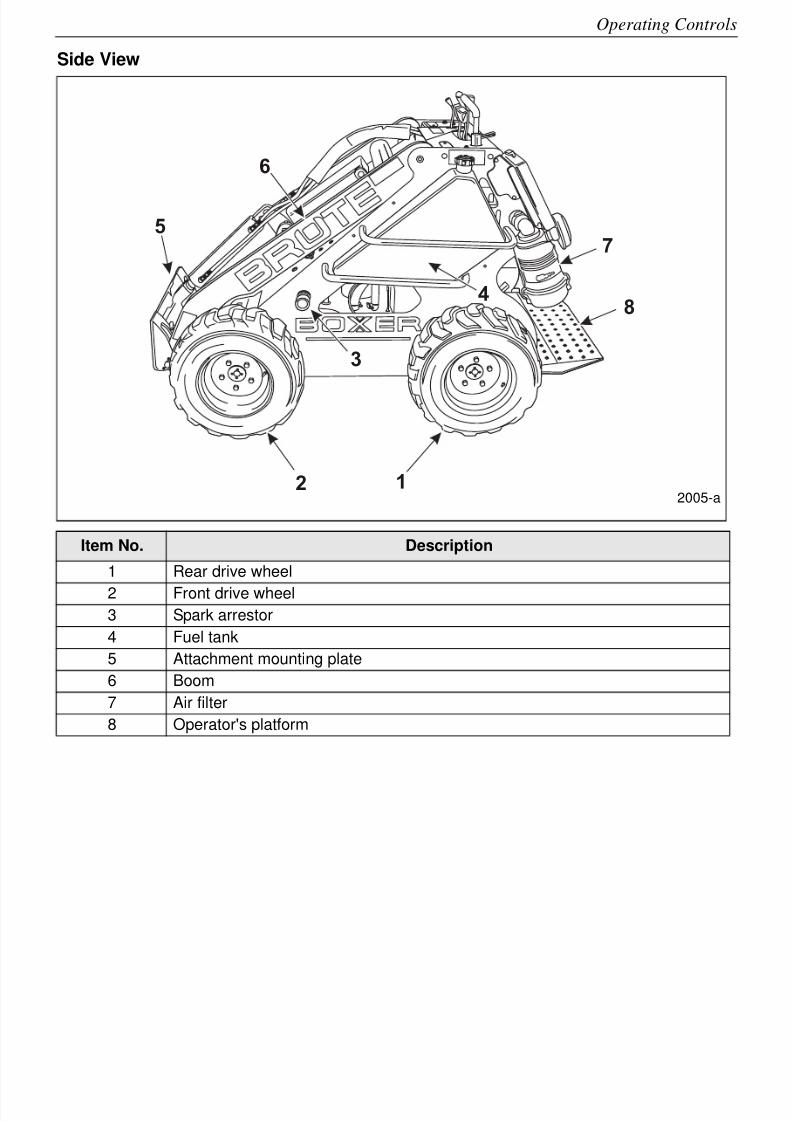
Side View
Item No. Description
1 Rear drive wheel
2 Front drive wheel
3 Spark arrestor
4 Fuel tank
5 Attachment mounting plate
6 Boom
7 Air filter
8 Operator's platform
8
5
6
7
4
3
2 12005-a
8/6/2019 Brute Operator's Manual
http://slidepdf.com/reader/full/brute-operators-manual 22/88
2-4
Operating Controls
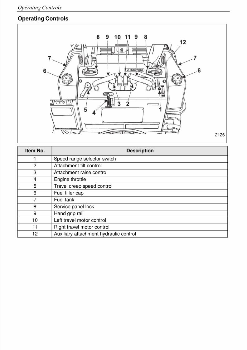
Operating Controls
Item No. Description
1 Speed range selector switch
2 Attachment tilt control
3 Attachment raise control
4 Engine throttle
5 Travel creep speed control
6 Fuel filler cap
7 Fuel tank
8 Service panel lock
9 Hand grip rail
10 Left travel motor control
11 Right travel motor control
12 Auxiliary attachment hydraulic control
2126
8/6/2019 Brute Operator's Manual
http://slidepdf.com/reader/full/brute-operators-manual 23/88
2-5
Operating Controls
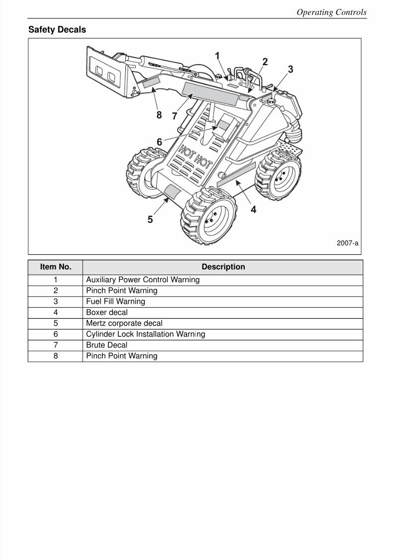
Safety Decals
Item No. Description
1 Auxiliary Power Control Warning
2 Pinch Point Warning3 Fuel Fill Warning
4 Boxer decal
5 Mertz corporate decal
6 Cylinder Lock Installation Warning
7 Brute Decal
8 Pinch Point Warning
12
3
4
5
6
78
2007-a
8/6/2019 Brute Operator's Manual
http://slidepdf.com/reader/full/brute-operators-manual 24/88
2-6
Operating Controls
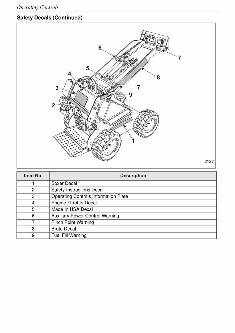
Safety Decals (Continued)
Item No. Description
1 Boxer Decal
2 Safety Instructions Decal
3 Operating Controls Information Plate
4 Engine Throttle Decal
5 Made In USA Decal
6 Auxiliary Power Control Warning
7 Pinch Point Warning
8 Brute Decal
9 Fuel Fill Warning
1
5
8
7
9
4
6
3
2
7
2127
8/6/2019 Brute Operator's Manual
http://slidepdf.com/reader/full/brute-operators-manual 25/88
2-7
Operating Controls
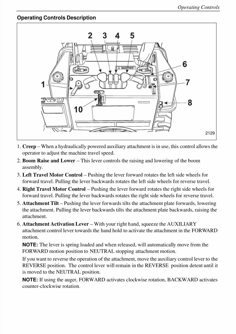
Operating Controls Description
1. Creep – When a hydraulically powered auxiliary attachment is in use, this control allows the
operator to adjust the machine travel speed.
2. Boom Raise and Lower – This lever controls the raising and lowering of the boom
assembly.
3. Left Travel Motor Control – Pushing the lever forward rotates the left side wheels forforward travel. Pulling the lever backwards rotates the left side wheels for reverse travel.
4. Right Travel Motor Control – Pushing the lever forward rotates the right side wheels for
forward travel. Pulling the lever backwards rotates the right side wheels for reverse travel.
5. Attachment Tilt – Pushing the lever forwards tilts the attachment plate forwards, lowering
the attachment. Pulling the lever backwards tilts the attachment plate backwards, raising the
attachment.
6. Attachment Activation Lever – With your right hand, squeeze the AUXILIARY
attachment control lever towards the hand hold to activate the attachment in the FORWARD
motion.
NOTE: The lever is spring loaded and when released, will automatically move from the
FORWARD motion position to NEUTRAL stopping attachment motion.
If you want to reverse the operation of the attachment, move the auxiliary control lever to the
REVERSE position. The control lever will remain in the REVERSE position detent until it
is moved to the NEUTRAL position.
NOTE: If using the auger, FORWARD activates clockwise rotation, BACKWARD activates
counter-clockwise rotation.
2129

8/6/2019 Brute Operator's Manual
http://slidepdf.com/reader/full/brute-operators-manual 26/88
2-8
Operating Controls
7. High/Low Speed Range Selector Switch – Selects the speed range that the travel speed
operates within.
8. Ignition Switch
9. Low Oil Warning Light – when the light turns on, it indicates that the engine oil level is
low. Shut down engine immediately and add oil.
10.Engine Throttle – The engine throttle is located on the control panel cowling, just
underneath the operating controls. Moving the control lever upwards increases the engine
speed and moving the lever downwards slows the engine to idle speed.
8/6/2019 Brute Operator's Manual
http://slidepdf.com/reader/full/brute-operators-manual 27/88
3-1
Section 3 – Pre-Start Inspection and Operation
IMPROPER USE OF THE COMPACT UTILITY LOADER COULD CAUSE SERIOUSINJURY OR DEATH. BEFORE OPERATING THE WHEEL LOADER, OR
PERFORMING MAINTENANCE, THE OPERATOR MUST READ AND
UNDERSTAND THE ENTIRE OPERATOR'S MANUAL, REVIEW MACHINE
CONTROLS, LOCATE AND REVIEW ALL WARNINGS AND SAFETY PLACARDS
AND RELEVANT OPERATOR SAFETY MATERIALS INCLUDING WRITTEN,
VISUAL, VIDEO OR VERBAL INSTRUCTIONS.
Pre-Start Inspection
It is very important to do a visual inspection of the machine before beginning operation. Thisinspection should include:
• Check all decals and warning signs for damage.
• Check engine oil.
• Check and refill gas tanks.
• Check hydraulic lines and hoses for signs of damage or leaks.
• Inspect the machine for any signs of damage or loose fasteners.
• Check fluid levels and any signs of leaking fluids.
• Do all Daily Service Checks.
• Check machine controls to make sure that they automatically return to the neutral position.
NOTE: The following procedures have several additional service checks and adjustments that
will need to be followed if your machine is equipped with a track drive system.
The following information presents details on these inspection points and service checks.
Daily Service ChecksTable 1: Service Cycle Table
Service Cycle - R = Replace ✓ = Check
***Under very wet, muddy, dusty or dirty working conditions more frequent lubrication may be required.
Activity Daily (10 Hours)
Fuel✓
and REngine Oil ✓ and A
Engine Oil Filter
Air Filter
Fuel Filter
Engine Idle Speed
Spark Plugs
Battery
Hydraulics
- Hydraulic Filter
- Hydraulic Fluid- Hydraulic Hoses
✓
✓
✓
Grease ✓***
Tires/Tracks ✓
Visual Check for Loose/Missing Fasteners ✓
Battery
DANGER
8/6/2019 Brute Operator's Manual
http://slidepdf.com/reader/full/brute-operators-manual 28/88
3-2
Pre-Start Inspection and Operation
Do the following pre-start service checks:
1. Check condition of all warning and instructional decals. Replace any damaged decals with
genuine CPI replacement decals.
2. Check engine oil -
• Make sure that the engine is OFF.
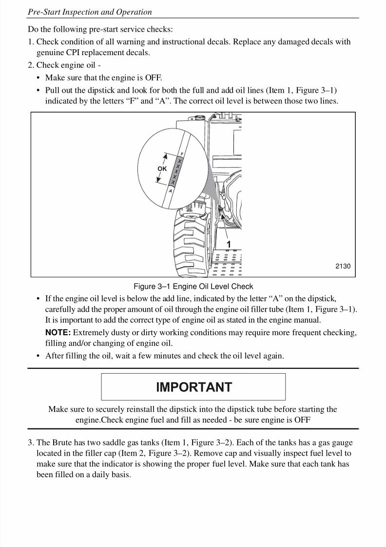
• Pull out the dipstick and look for both the full and add oil lines (Item 1, Figure 3–1)
indicated by the letters “F” and “A”. The correct oil level is between those two lines.
Figure 3–1 Engine Oil Level Check• If the engine oil level is below the add line, indicated by the letter “A” on the dipstick,
carefully add the proper amount of oil through the engine oil filler tube (Item 1, Figure 3–1).
It is important to add the correct type of engine oil as stated in the engine manual.
NOTE: Extremely dusty or dirty working conditions may require more frequent checking,
filling and/or changing of engine oil.
• After filling the oil, wait a few minutes and check the oil level again.
Make sure to securely reinstall the dipstick into the dipstick tube before starting the
engine.Check engine fuel and fill as needed - be sure engine is OFF
3. The Brute has two saddle gas tanks (Item 1, Figure 3–2). Each of the tanks has a gas gauge
located in the filler cap (Item 2, Figure 3–2). Remove cap and visually inspect fuel level to
make sure that the indicator is showing the proper fuel level. Make sure that each tank has
been filled on a daily basis.
1
OK
x
x
x
x
x
F
A
2130
IMPORTANT
8/6/2019 Brute Operator's Manual
http://slidepdf.com/reader/full/brute-operators-manual 29/88
3-3
Pre-Start Inspection and Operation
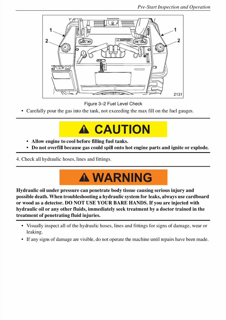
Figure 3–2 Fuel Level Check
• Carefully pour the gas into the tank, not exceeding the max fill on the fuel gauges.
• Allow engine to cool before filling fuel tanks.
• Do not overfill because gas could spill onto hot engine parts and ignite or explode.
4. Check all hydraulic hoses, lines and fittings.
Hydraulic oil under pressure can penetrate body tissue causing serious injury and
possible death. When troubleshooting a hydraulic system for leaks, always use cardboard
or wood as a detector. DO NOT USE YOUR BARE HANDS. If you are injected with
hydraulic oil or any other fluids, immediately seek treatment by a doctor trained in the
treatment of penetrating fluid injuries.
• Visually inspect all of the hydraulic hoses, lines and fittings for signs of damage, wear orleaking.
• If any signs of damage are visible, do not operate the machine until repairs have been made.
2131
CAUTION
WARNING

8/6/2019 Brute Operator's Manual
http://slidepdf.com/reader/full/brute-operators-manual 30/88
3-4
Pre-Start Inspection and Operation
• Some examples of common hydraulic hose damage are shown in Figure 3–3.
Figure 3–3 Hydraulic Hose Damage
1. End fittings damaged or leaking
2. Outer covering chafed or cut, and wire reinforcing is exposed
3. Hose shows signs of kinking or crushing
4. Outer covering ballooning
5. Check for loose or missing fasteners
• Inspect for any loose or missing bolts.
• Tighten or replace any missing bolts immediately.
6. While you are performing the daily maintenance, inspect the machine for any signs of
damage, such as missing or damaged components, cracked welds, etc.
7. Check all 4 tires for the proper tire pressure. The proper pressure level is shown on the side
of the tire.a. Check the track assemblies to make sure that:
– The tracks are in good condition and are not showing any signs of wear.
– Track tension is properly set.
– Track drive motors are not leaking oil or hydraulic fluid.
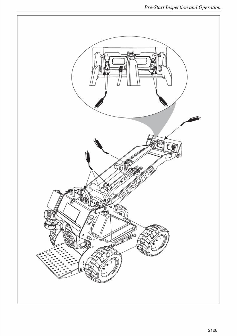
8. Grease pivot shafts with proper type of grease. There are 10 grease points on this machine,
see Figure 3–4 and Figure 3–5.
Before starting the engine:
• Move all hydraulic control levers forward and release the lever. Make sure that
each lever automatically returns to the Neutral position.
• Move all hydraulic control levers rearward and release the lever. Make sure that
each lever automatically returns to the Neutral position.
• The Auxiliary Control Lever will remain in either the Forward or Reverse position
detents until it is manually moved to the Neutral position.• If any of the levers, other than the Auxiliary Control Lever, does not automatically
return to the Neutral position, DO NOT use the machine until repairs have been
completed.
1
3
4
2
2051
CAUTION
8/6/2019 Brute Operator's Manual
http://slidepdf.com/reader/full/brute-operators-manual 31/88
3-5
Pre-Start Inspection and Operation
Figure 3–4 Lubrication Points
2128
8/6/2019 Brute Operator's Manual
http://slidepdf.com/reader/full/brute-operators-manual 32/88
3-6
Pre-Start Inspection and Operation
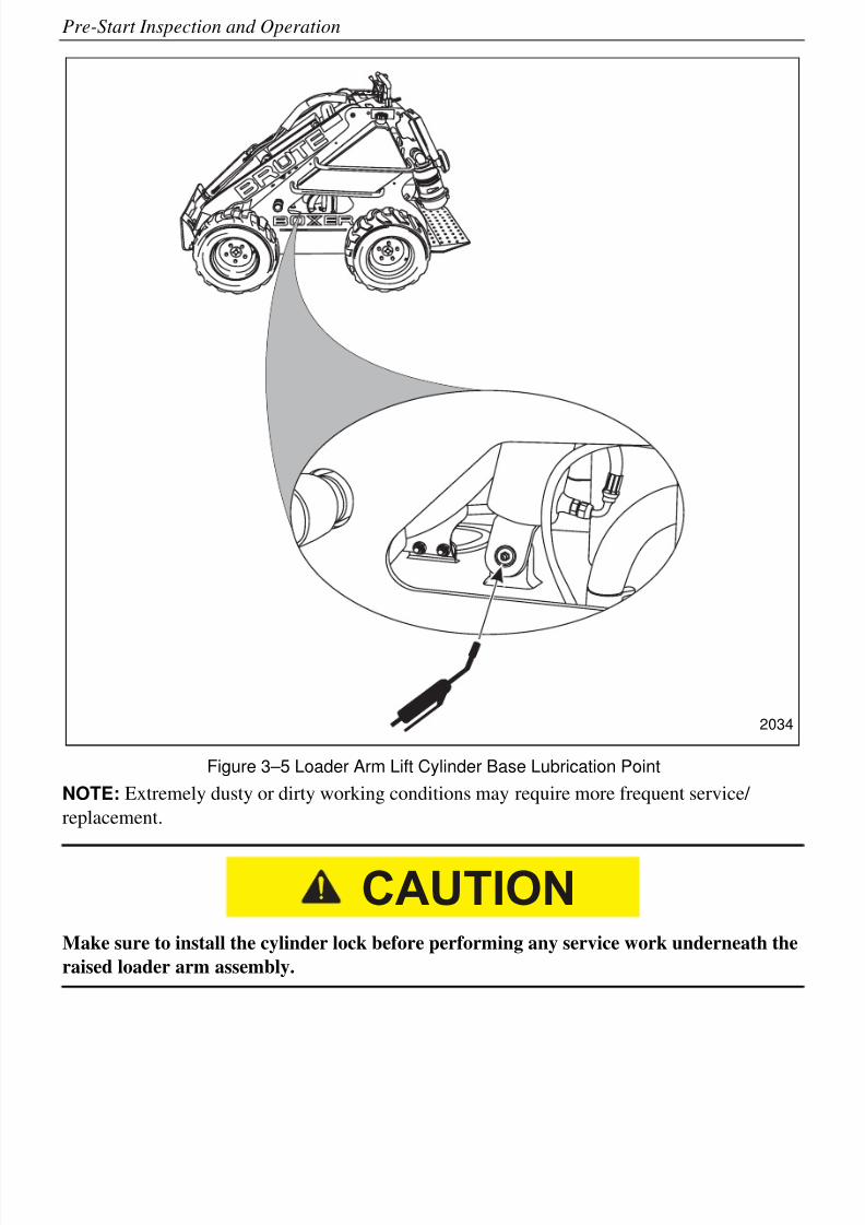
Figure 3–5 Loader Arm Lift Cylinder Base Lubrication Point
NOTE: Extremely dusty or dirty working conditions may require more frequent service/
replacement.
Make sure to install the cylinder lock before performing any service work underneath the
raised loader arm assembly.
2034
CAUTION
8/6/2019 Brute Operator's Manual
http://slidepdf.com/reader/full/brute-operators-manual 33/88
3-7
Pre-Start Inspection and Operation
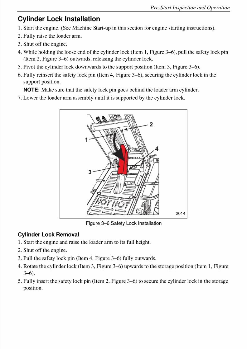
Cylinder Lock Installation
1. Start the engine. (See Machine Start-up in this section for engine starting instructions).
2. Fully raise the loader arm.
3. Shut off the engine.
4. While holding the loose end of the cylinder lock (Item 1, Figure 3–6), pull the safety lock pin
(Item 2, Figure 3–6) outwards, releasing the cylinder lock.5. Pivot the cylinder lock downwards to the support position (Item 3, Figure 3–6).
6. Fully reinsert the safety lock pin (Item 4, Figure 3–6), securing the cylinder lock in the
support position.
NOTE: Make sure that the safety lock pin goes behind the loader arm cylinder.
7. Lower the loader arm assembly until it is supported by the cylinder lock.
Figure 3–6 Safety Lock Installation
Cylinder Lock Removal
1. Start the engine and raise the loader arm to its full height.2. Shut off the engine.
3. Pull the safety lock pin (Item 4, Figure 3–6) fully outwards.
4. Rotate the cylinder lock (Item 3, Figure 3–6) upwards to the storage position (Item 1, Figure
3–6).
5. Fully insert the safety lock pin (Item 2, Figure 3–6) to secure the cylinder lock in the storage
position.
2014
8/6/2019 Brute Operator's Manual
http://slidepdf.com/reader/full/brute-operators-manual 34/88
3-8
Pre-Start Inspection and Operation
Operating Instructions
Machine Start-up
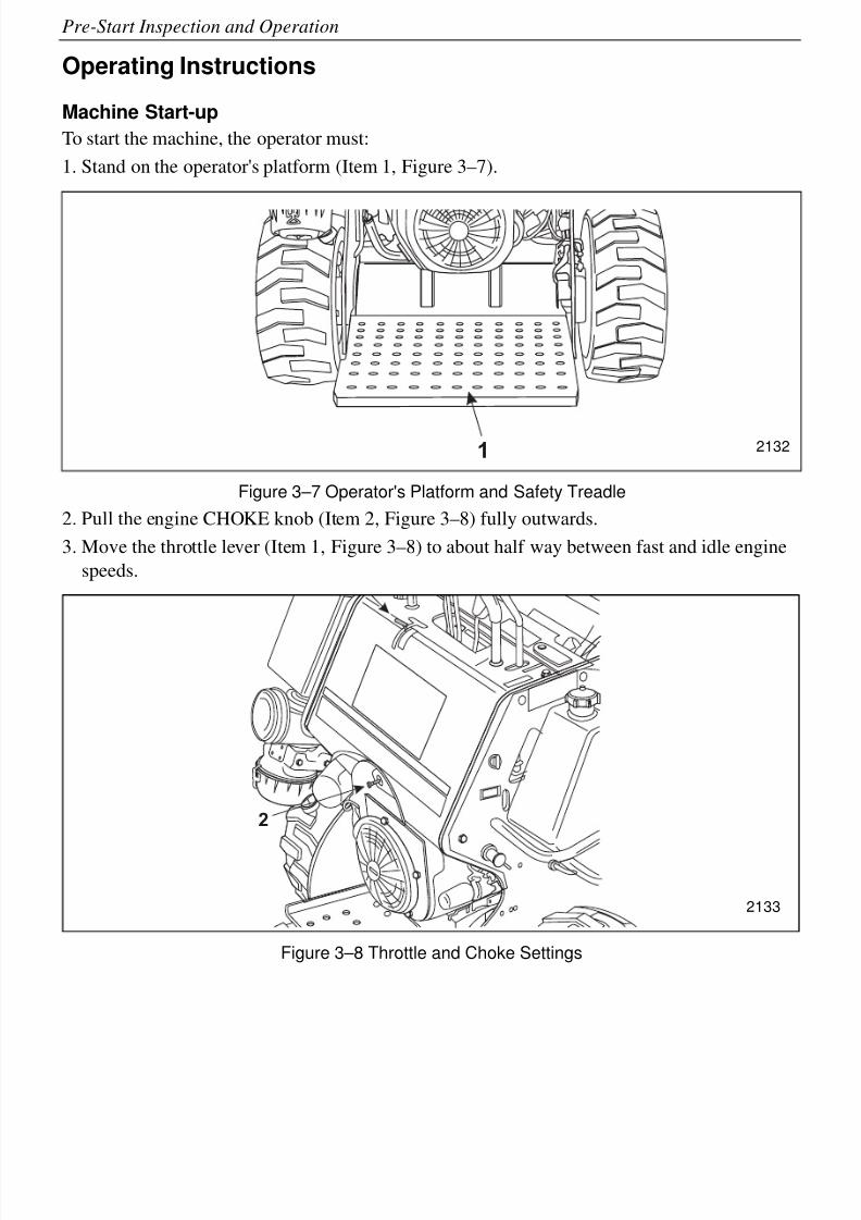
To start the machine, the operator must:
1. Stand on the operator's platform (Item 1, Figure 3–7).
Figure 3–7 Operator's Platform and Safety Treadle
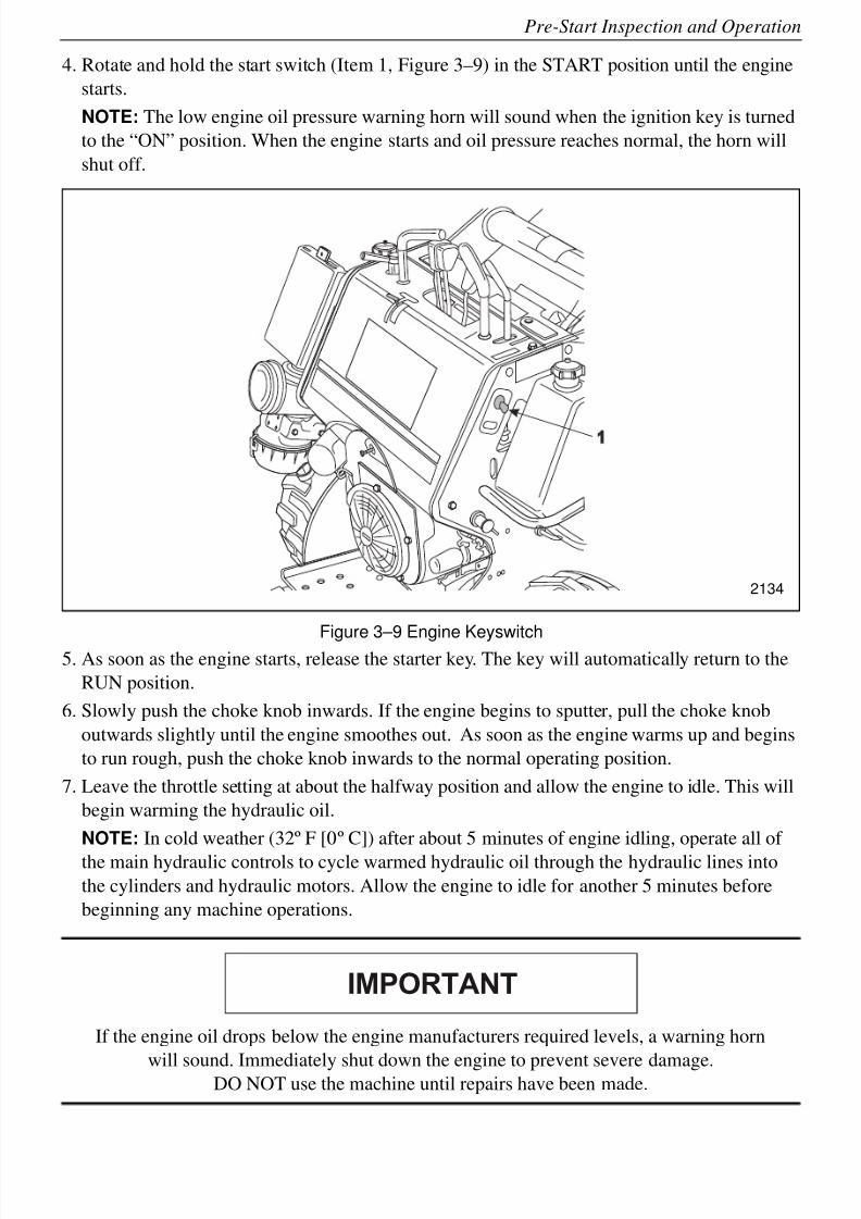
2. Pull the engine CHOKE knob (Item 2, Figure 3–8) fully outwards.
3. Move the throttle lever (Item 1, Figure 3–8) to about half way between fast and idle engine
speeds.
Figure 3–8 Throttle and Choke Settings
1
2
2132
2133
8/6/2019 Brute Operator's Manual
http://slidepdf.com/reader/full/brute-operators-manual 35/88
3-9
Pre-Start Inspection and Operation
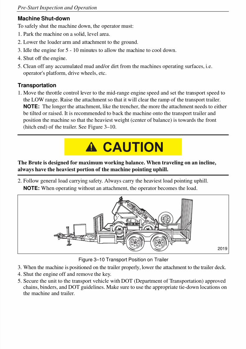
4. Rotate and hold the start switch (Item 1, Figure 3–9) in the START position until the engine
starts.
NOTE: The low engine oil pressure warning horn will sound when the ignition key is turned
to the “ON” position. When the engine starts and oil pressure reaches normal, the horn will
shut off.
Figure 3–9 Engine Keyswitch5. As soon as the engine starts, release the starter key. The key will automatically return to the
RUN position.
6. Slowly push the choke knob inwards. If the engine begins to sputter, pull the choke knob
outwards slightly until the engine smoothes out. As soon as the engine warms up and begins
to run rough, push the choke knob inwards to the normal operating position.
7. Leave the throttle setting at about the halfway position and allow the engine to idle. This will
begin warming the hydraulic oil.
NOTE: In cold weather (32º F [0º C]) after about 5 minutes of engine idling, operate all of
the main hydraulic controls to cycle warmed hydraulic oil through the hydraulic lines into
the cylinders and hydraulic motors. Allow the engine to idle for another 5 minutes before
beginning any machine operations.
If the engine oil drops below the engine manufacturers required levels, a warning horn
will sound. Immediately shut down the engine to prevent severe damage.DO NOT use the machine until repairs have been made.
1
2134
IMPORTANT
8/6/2019 Brute Operator's Manual
http://slidepdf.com/reader/full/brute-operators-manual 36/88
3-10
Pre-Start Inspection and Operation
Machine Shut-down
To safely shut the machine down, the operator must:
1. Park the machine on a solid, level area.
2. Lower the loader arm and attachment to the ground.
3. Idle the engine for 5 - 10 minutes to allow the machine to cool down.
4. Shut off the engine.5. Clean off any accumulated mud and/or dirt from the machines operating surfaces, i.e.
operator's platform, drive wheels, etc.
Transportation
1. Move the throttle control lever to the mid-range engine speed and set the transport speed to
the LOW range. Raise the attachment so that it will clear the ramp of the transport trailer.
NOTE: The longer the attachment, like the trencher, the more the attachment needs to either
be tilted or raised. It is recommended to back the machine onto the transport trailer and
position the machine so that the heaviest weight (center of balance) is towards the front(hitch end) of the trailer. See Figure 3–10.
The Brute is designed for maximum working balance. When traveling on an incline,
always have the heaviest portion of the machine pointing uphill.
2. Follow general load carrying safety. Always carry the heaviest load pointing uphill.NOTE: When operating without an attachment, the operator becomes the load.
Figure 3–10 Transport Position on Trailer
3. When the machine is positioned on the trailer properly, lower the attachment to the trailer deck.
4. Shut the engine off and remove the key.
5. Secure the unit to the transport vehicle with DOT (Department of Transportation) approvedchains, binders, and DOT guidelines. Make sure to use the appropriate tie-down locations onthe machine and trailer.
CAUTION
2019
8/6/2019 Brute Operator's Manual
http://slidepdf.com/reader/full/brute-operators-manual 37/88
3-11
Pre-Start Inspection and Operation
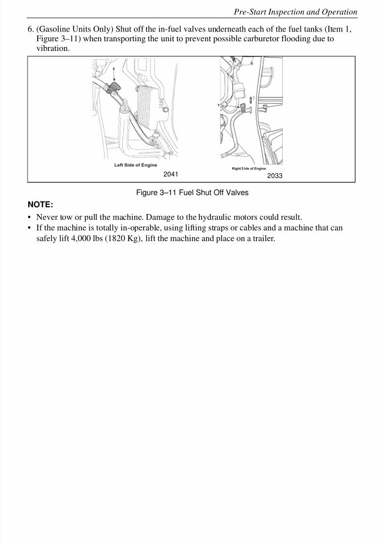
6. (Gasoline Units Only) Shut off the in-fuel valves underneath each of the fuel tanks (Item 1,Figure 3–11) when transporting the unit to prevent possible carburetor flooding due tovibration.
Figure 3–11 Fuel Shut Off Valves
NOTE:
• Never tow or pull the machine. Damage to the hydraulic motors could result.
• If the machine is totally in-operable, using lifting straps or cables and a machine that can
safely lift 4,000 lbs (1820 Kg), lift the machine and place on a trailer.
1
Left Side of Engine
1
Right Side of Engine
2041 2033
8/6/2019 Brute Operator's Manual
http://slidepdf.com/reader/full/brute-operators-manual 38/88
3-12
Pre-Start Inspection and Operation
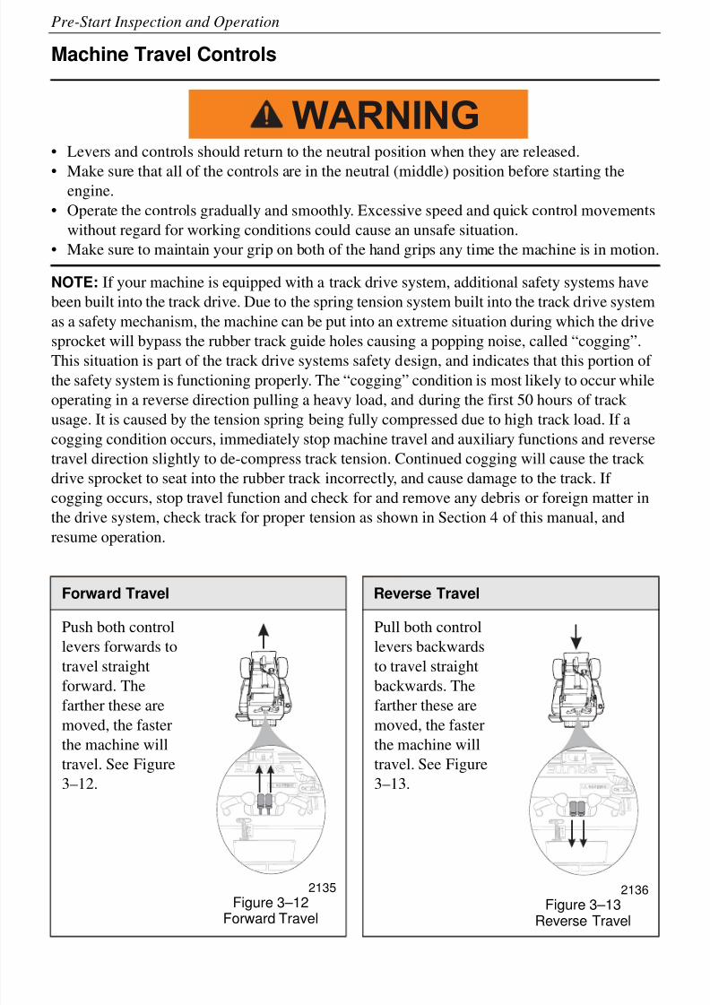
Machine Travel Controls
• Levers and controls should return to the neutral position when they are released.
• Make sure that all of the controls are in the neutral (middle) position before starting theengine.
• Operate the controls gradually and smoothly. Excessive speed and quick control movements
without regard for working conditions could cause an unsafe situation.
• Make sure to maintain your grip on both of the hand grips any time the machine is in motion.
NOTE: If your machine is equipped with a track drive system, additional safety systems have
been built into the track drive. Due to the spring tension system built into the track drive system
as a safety mechanism, the machine can be put into an extreme situation during which the drive
sprocket will bypass the rubber track guide holes causing a popping noise, called “cogging”.
This situation is part of the track drive systems safety design, and indicates that this portion of
the safety system is functioning properly. The “cogging” condition is most likely to occur while
operating in a reverse direction pulling a heavy load, and during the first 50 hours of track
usage. It is caused by the tension spring being fully compressed due to high track load. If a
cogging condition occurs, immediately stop machine travel and auxiliary functions and reverse
travel direction slightly to de-compress track tension. Continued cogging will cause the track
drive sprocket to seat into the rubber track incorrectly, and cause damage to the track. If
cogging occurs, stop travel function and check for and remove any debris or foreign matter in
the drive system, check track for proper tension as shown in Section 4 of this manual, and
resume operation.
Forward Travel Reverse Travel
Push both control
levers forwards to
travel straight
forward. The
farther these aremoved, the faster
the machine will
travel. See Figure
3–12.
2135
Figure 3–12Forward Travel
Pull both control
levers backwards
to travel straight
backwards. The
farther these aremoved, the faster
the machine will
travel. See Figure
3–13.
2136
Figure 3–13Reverse Travel
WARNING
8/6/2019 Brute Operator's Manual
http://slidepdf.com/reader/full/brute-operators-manual 39/88
3-13
Pre-Start Inspection and Operation
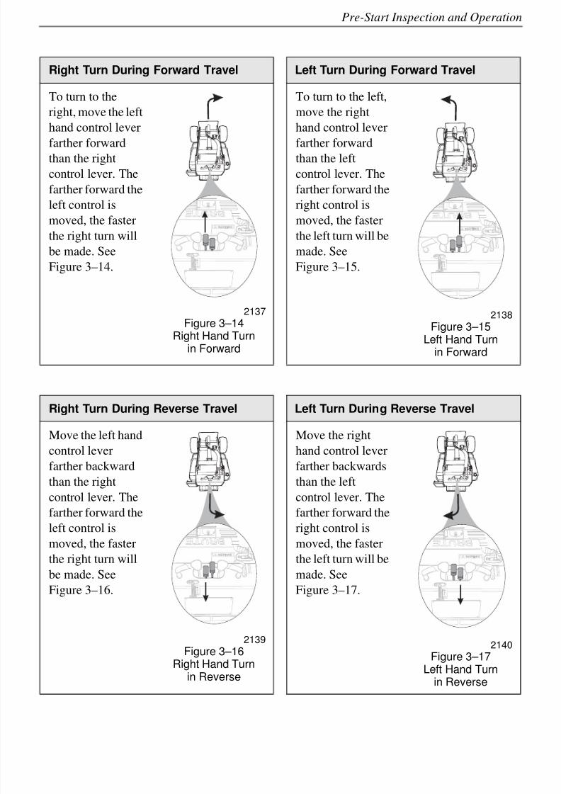
Right Turn During Forward Travel Left Turn During Forward Travel
To turn to the
right, move the left
hand control lever
farther forward
than the right
control lever. The
farther forward the
left control is
moved, the faster
the right turn will
be made. See
Figure 3–14.
2137
Figure 3–14Right Hand Turn
in Forward
To turn to the left,
move the right
hand control lever
farther forward
than the left
control lever. The
farther forward the
right control is
moved, the faster
the left turn will be
made. See
Figure 3–15.
2138
Figure 3–15Left Hand Turn
in Forward
Right Turn During Reverse Travel Left Turn During Reverse Travel
Move the left hand
control lever
farther backward
than the right
control lever. The
farther forward the
left control is
moved, the faster
the right turn willbe made. See
Figure 3–16.
2139
Figure 3–16Right Hand Turn
in Reverse
Move the right
hand control lever
farther backwards
than the left
control lever. The
farther forward the
right control is
moved, the faster
the left turn will bemade. See
Figure 3–17.
2140
Figure 3–17Left Hand Turn
in Reverse
8/6/2019 Brute Operator's Manual
http://slidepdf.com/reader/full/brute-operators-manual 40/88
3-14
Pre-Start Inspection and Operation
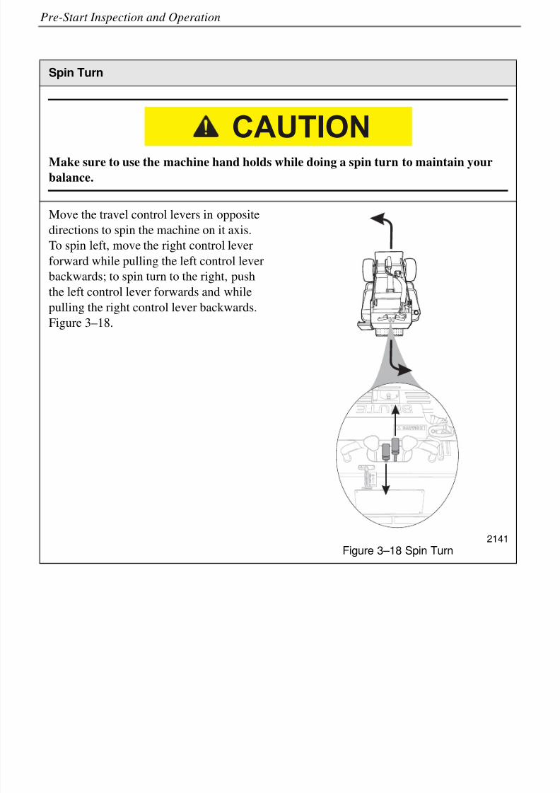
Spin Turn
Make sure to use the machine hand holds while doing a spin turn to maintain your
balance.
Move the travel control levers in opposite
directions to spin the machine on it axis.
To spin left, move the right control lever
forward while pulling the left control lever
backwards; to spin turn to the right, pushthe left control lever forwards and while
pulling the right control lever backwards.
Figure 3–18.
2141
Figure 3–18 Spin Turn
CAUTION
8/6/2019 Brute Operator's Manual
http://slidepdf.com/reader/full/brute-operators-manual 41/88
3-15
Pre-Start Inspection and Operation
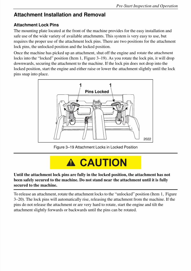
Attachment Installation and Removal
Attachment Lock Pins
The mounting plate located at the front of the machine provides for the easy installation and
safe use of the wide variety of available attachments. This system is very easy to use, but
requires the proper use of the attachment lock pins. There are two positions for the attachment
lock pins, the unlocked position and the locked position.Once the machine has picked up an attachment, shut off the engine and rotate the attachment
locks into the “locked” position (Item 1, Figure 3–19). As you rotate the lock pin, it will drop
downwards, securing the attachment to the machine. If the lock pin does not drop into the
locked position, start the engine and either raise or lower the attachment slightly until the lock
pins snap into place.
Figure 3–19 Attachment Locks in Locked Position
Until the attachment lock pins are fully in the locked position, the attachment has not
been safely secured to the machine. Do not stand near the attachment until it is fully
secured to the machine.
To release an attachment, rotate the attachment locks to the “unlocked” position (Item 1, Figure
3–20). The lock pins will automatically rise, releasing the attachment from the machine. If the
pins do not release the attachment or are very hard to rotate, start the engine and tilt the
attachment slightly forwards or backwards until the pins can be rotated.
1 1
2022
Pins Locked
CAUTION
8/6/2019 Brute Operator's Manual
http://slidepdf.com/reader/full/brute-operators-manual 42/88
3-16
Pre-Start Inspection and Operation
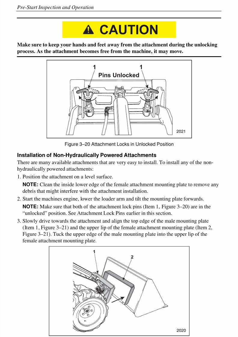
Make sure to keep your hands and feet away from the attachment during the unlocking
process. As the attachment becomes free from the machine, it may move.
Figure 3–20 Attachment Locks in Unlocked Position
Installation of Non-Hydraulically Powered Attachments
There are many available attachments that are very easy to install. To install any of the non-
hydraulically powered attachments:
1. Position the attachment on a level surface.NOTE: Clean the inside lower edge of the female attachment mounting plate to remove any
debris that might interfere with the attachment installation.
2. Start the machines engine, lower the loader arm and tilt the mounting plate forwards.
NOTE: Make sure that both of the attachment lock pins (Item 1, Figure 3–20) are in the
“unlocked” position. See Attachment Lock Pins earlier in this section.
3. Slowly drive towards the attachment and align the top edge of the male mounting plate
(Item 1, Figure 3–21) and the upper lip of the female attachment mounting plate (Item 2,
Figure 3–21). Tuck the upper edge of the male mounting plate into the upper lip of thefemale attachment mounting plate.
Figure 3–21 Non-powered Attachment Installation
CAUTION
1 1
Pins Unlocked
2021
1
2
2020
8/6/2019 Brute Operator's Manual
http://slidepdf.com/reader/full/brute-operators-manual 43/88
3-17
Pre-Start Inspection and Operation
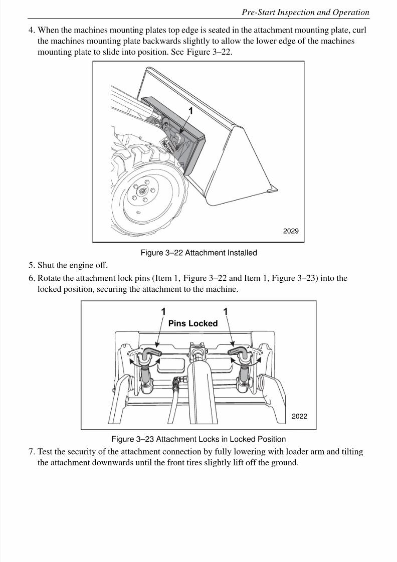
4. When the machines mounting plates top edge is seated in the attachment mounting plate, curl
the machines mounting plate backwards slightly to allow the lower edge of the machines
mounting plate to slide into position. See Figure 3–22.
Figure 3–22 Attachment Installed
5. Shut the engine off.
6. Rotate the attachment lock pins (Item 1, Figure 3–22 and Item 1, Figure 3–23) into the
locked position, securing the attachment to the machine.
Figure 3–23 Attachment Locks in Locked Position
7. Test the security of the attachment connection by fully lowering with loader arm and tilting
the attachment downwards until the front tires slightly lift off the ground.
1
2029
1 1
2022
Pins Locked
8/6/2019 Brute Operator's Manual
http://slidepdf.com/reader/full/brute-operators-manual 44/88
3-18
Pre-Start Inspection and Operation
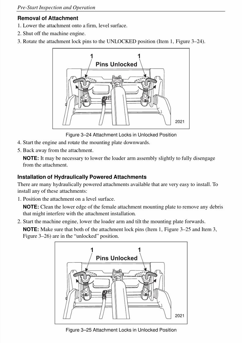
Removal of Attachment
1. Lower the attachment onto a firm, level surface.
2. Shut off the machine engine.
3. Rotate the attachment lock pins to the UNLOCKED position (Item 1, Figure 3–24).
Figure 3–24 Attachment Locks in Unlocked Position
4. Start the engine and rotate the mounting plate downwards.
5. Back away from the attachment.
NOTE: It may be necessary to lower the loader arm assembly slightly to fully disengage
from the attachment.
Installation of Hydraulically Powered Attachments
There are many hydraulically powered attachments available that are very easy to install. To
install any of these attachments:
1. Position the attachment on a level surface.
NOTE: Clean the lower edge of the female attachment mounting plate to remove any debris
that might interfere with the attachment installation.
2. Start the machine engine, lower the loader arm and tilt the mounting plate forwards.
NOTE: Make sure that both of the attachment lock pins (Item 1, Figure 3–25 and Item 3,
Figure 3–26) are in the “unlocked” position.
Figure 3–25 Attachment Locks in Unlocked Position
1 1
Pins Unlocked
2021
1 1
Pins Unlocked
2021
8/6/2019 Brute Operator's Manual
http://slidepdf.com/reader/full/brute-operators-manual 45/88
3-19
Pre-Start Inspection and Operation
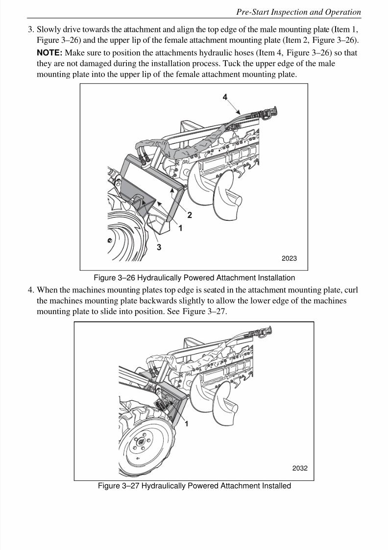
3. Slowly drive towards the attachment and align the top edge of the male mounting plate (Item 1,
Figure 3–26) and the upper lip of the female attachment mounting plate (Item 2, Figure 3–26).
NOTE: Make sure to position the attachments hydraulic hoses (Item 4, Figure 3–26) so that
they are not damaged during the installation process. Tuck the upper edge of the male
mounting plate into the upper lip of the female attachment mounting plate.
Figure 3–26 Hydraulically Powered Attachment Installation
4. When the machines mounting plates top edge is seated in the attachment mounting plate, curlthe machines mounting plate backwards slightly to allow the lower edge of the machines
mounting plate to slide into position. See Figure 3–27.
Figure 3–27 Hydraulically Powered Attachment Installed
2
1
4
3
2023
1
2032
8/6/2019 Brute Operator's Manual
http://slidepdf.com/reader/full/brute-operators-manual 46/88
3-20
Pre-Start Inspection and Operation
5. Shut the engine off.
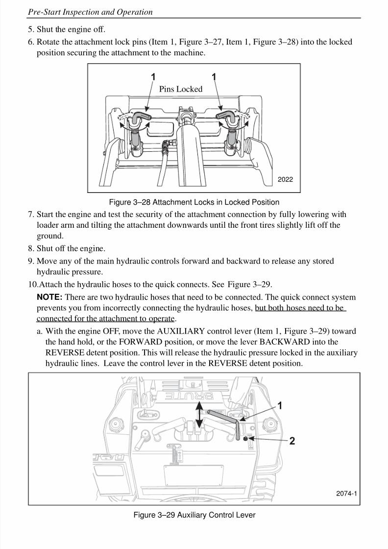
6. Rotate the attachment lock pins (Item 1, Figure 3–27, Item 1, Figure 3–28) into the locked
position securing the attachment to the machine.
Figure 3–28 Attachment Locks in Locked Position
7. Start the engine and test the security of the attachment connection by fully lowering with
loader arm and tilting the attachment downwards until the front tires slightly lift off the
ground.
8. Shut off the engine.
9. Move any of the main hydraulic controls forward and backward to release any stored
hydraulic pressure.
10.Attach the hydraulic hoses to the quick connects. See Figure 3–29.NOTE: There are two hydraulic hoses that need to be connected. The quick connect system
prevents you from incorrectly connecting the hydraulic hoses, but both hoses need to be
connected for the attachment to operate.
a. With the engine OFF, move the AUXILIARY control lever (Item 1, Figure 3–29) toward
the hand hold, or the FORWARD position, or move the lever BACKWARD into the
REVERSE detent position. This will release the hydraulic pressure locked in the auxiliary
hydraulic lines. Leave the control lever in the REVERSE detent position.
Figure 3–29 Auxiliary Control Lever
1 1
2022
Pins Locked
1
2
2074-1
8/6/2019 Brute Operator's Manual
http://slidepdf.com/reader/full/brute-operators-manual 47/88
3-21
Pre-Start Inspection and Operation
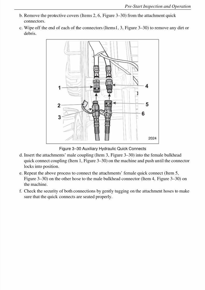
b. Remove the protective covers (Items 2, 6, Figure 3–30) from the attachment quick
connectors.
c. Wipe off the end of each of the connectors (Items1, 3, Figure 3–30) to remove any dirt or
debris.
Figure 3–30 Auxiliary Hydraulic Quick Connects
d. Insert the attachments’ male coupling (Item 3, Figure 3–30) into the female bulkhead
quick connect coupling (Item 1, Figure 3–30) on the machine and push until the connector
locks into position.
e. Repeat the above process to connect the attachments’ female quick connect (Item 5,
Figure 3–30) on the other hose to the male bulkhead connector (Item 4, Figure 3–30) on
the machine.
f. Check the security of both connections by gently tugging on the attachment hoses to make
sure that the quick connects are seated properly.
1
2
4
5
63
2024
8/6/2019 Brute Operator's Manual
http://slidepdf.com/reader/full/brute-operators-manual 48/88
3-22
Pre-Start Inspection and Operation
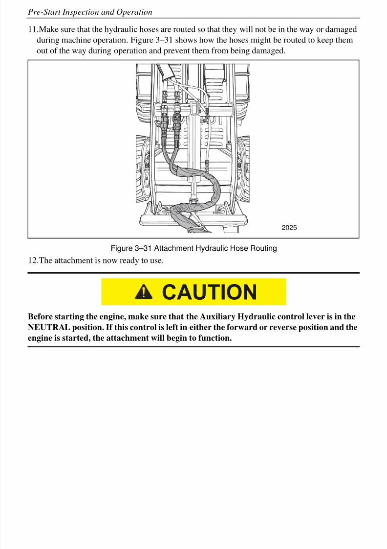
11.Make sure that the hydraulic hoses are routed so that they will not be in the way or damaged
during machine operation. Figure 3–31 shows how the hoses might be routed to keep them
out of the way during operation and prevent them from being damaged.
Figure 3–31 Attachment Hydraulic Hose Routing
12.The attachment is now ready to use.
Before starting the engine, make sure that the Auxiliary Hydraulic control lever is in the
NEUTRAL position. If this control is left in either the forward or reverse position and the
engine is started, the attachment will begin to function.
2025
CAUTION
8/6/2019 Brute Operator's Manual
http://slidepdf.com/reader/full/brute-operators-manual 49/88
3-23
Pre-Start Inspection and Operation
Operating Instructions for a Hydraulic Attachment
1. Move the engine throttle to the full speed setting.
Raise the attachment off the ground and position it for use.
• Make sure that you are standing on the operator's platform. DO NOT step off of
the platform when the auxiliary attachment's power is engaged.
• If you release the AUXILIARY hand control/operator presence control, the
attachment will automatically stop all motion.
• The Auxiliary Hydraulics will not function properly unless the HIGH/LOW switch
in set to the HIGH position.
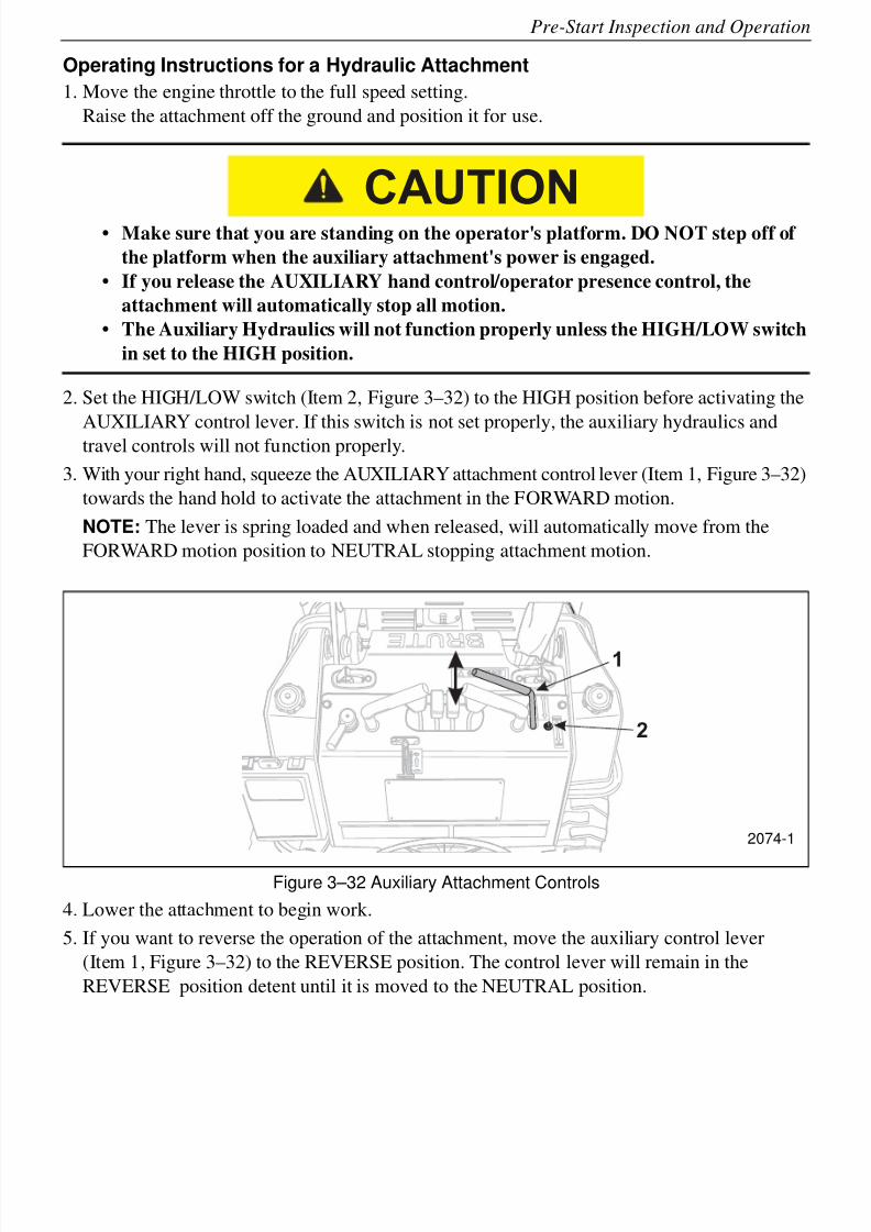
2. Set the HIGH/LOW switch (Item 2, Figure 3–32) to the HIGH position before activating the
AUXILIARY control lever. If this switch is not set properly, the auxiliary hydraulics andtravel controls will not function properly.
3. With your right hand, squeeze the AUXILIARY attachment control lever (Item 1, Figure 3–32)
towards the hand hold to activate the attachment in the FORWARD motion.
NOTE: The lever is spring loaded and when released, will automatically move from the
FORWARD motion position to NEUTRAL stopping attachment motion.
Figure 3–32 Auxiliary Attachment Controls
4. Lower the attachment to begin work.
5. If you want to reverse the operation of the attachment, move the auxiliary control lever
(Item 1, Figure 3–32) to the REVERSE position. The control lever will remain in the
REVERSE position detent until it is moved to the NEUTRAL position.
CAUTION
1
2
2074-1
8/6/2019 Brute Operator's Manual
http://slidepdf.com/reader/full/brute-operators-manual 50/88
3-24
Pre-Start Inspection and Operation
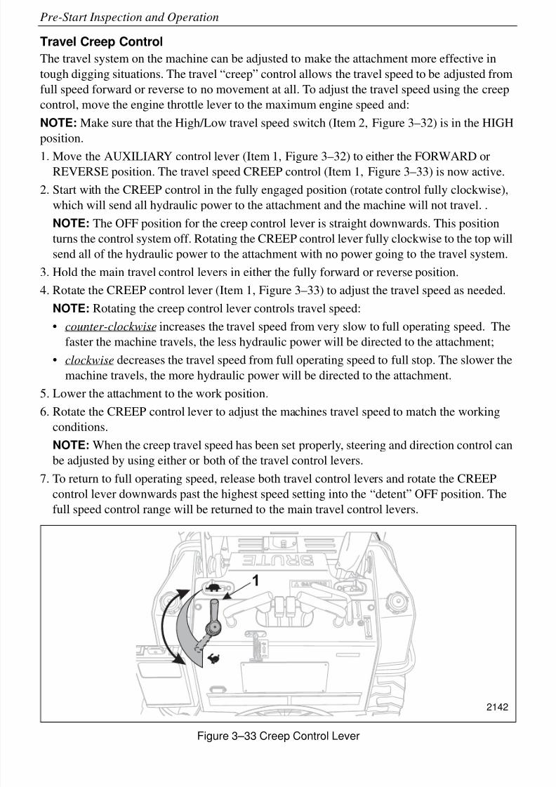
Travel Creep Control
The travel system on the machine can be adjusted to make the attachment more effective in
tough digging situations. The travel “creep” control allows the travel speed to be adjusted from
full speed forward or reverse to no movement at all. To adjust the travel speed using the creep
control, move the engine throttle lever to the maximum engine speed and:
NOTE: Make sure that the High/Low travel speed switch (Item 2, Figure 3–32) is in the HIGH
position.1. Move the AUXILIARY control lever (Item 1, Figure 3–32) to either the FORWARD or
REVERSE position. The travel speed CREEP control (Item 1, Figure 3–33) is now active.
2. Start with the CREEP control in the fully engaged position (rotate control fully clockwise),
which will send all hydraulic power to the attachment and the machine will not travel. .
NOTE: The OFF position for the creep control lever is straight downwards. This position
turns the control system off. Rotating the CREEP control lever fully clockwise to the top will
send all of the hydraulic power to the attachment with no power going to the travel system.
3. Hold the main travel control levers in either the fully forward or reverse position.4. Rotate the CREEP control lever (Item 1, Figure 3–33) to adjust the travel speed as needed.
NOTE: Rotating the creep control lever controls travel speed:
• counter-clockwise increases the travel speed from very slow to full operating speed. The
faster the machine travels, the less hydraulic power will be directed to the attachment;
• clockwise decreases the travel speed from full operating speed to full stop. The slower the
machine travels, the more hydraulic power will be directed to the attachment.
5. Lower the attachment to the work position.
6. Rotate the CREEP control lever to adjust the machines travel speed to match the workingconditions.
NOTE: When the creep travel speed has been set properly, steering and direction control can
be adjusted by using either or both of the travel control levers.
7. To return to full operating speed, release both travel control levers and rotate the CREEP
control lever downwards past the highest speed setting into the “detent” OFF position. The
full speed control range will be returned to the main travel control levers.
Figure 3–33 Creep Control Lever
1
2142
8/6/2019 Brute Operator's Manual
http://slidepdf.com/reader/full/brute-operators-manual 51/88
3-25
Pre-Start Inspection and Operation
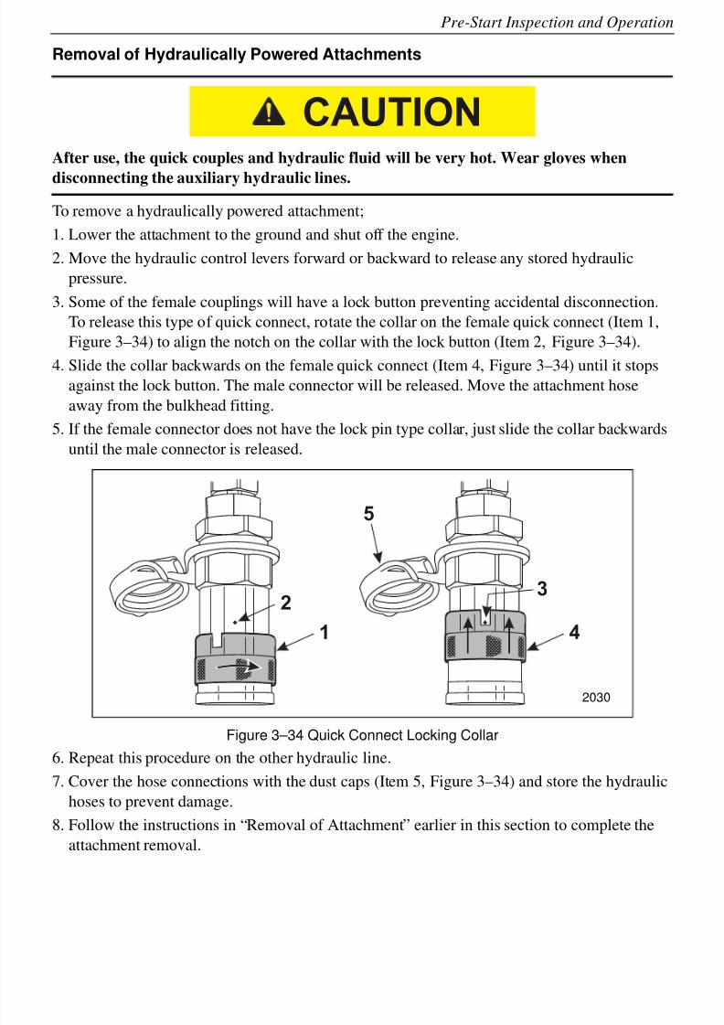
Removal of Hydraulically Powered Attachments
After use, the quick couples and hydraulic fluid will be very hot. Wear gloves when
disconnecting the auxiliary hydraulic lines.
To remove a hydraulically powered attachment;
1. Lower the attachment to the ground and shut off the engine.
2. Move the hydraulic control levers forward or backward to release any stored hydraulic
pressure.
3. Some of the female couplings will have a lock button preventing accidental disconnection.
To release this type of quick connect, rotate the collar on the female quick connect (Item 1,
Figure 3–34) to align the notch on the collar with the lock button (Item 2, Figure 3–34).
4. Slide the collar backwards on the female quick connect (Item 4, Figure 3–34) until it stops
against the lock button. The male connector will be released. Move the attachment hose
away from the bulkhead fitting.
5. If the female connector does not have the lock pin type collar, just slide the collar backwards
until the male connector is released.
Figure 3–34 Quick Connect Locking Collar
6. Repeat this procedure on the other hydraulic line.
7. Cover the hose connections with the dust caps (Item 5, Figure 3–34) and store the hydraulic
hoses to prevent damage.
8. Follow the instructions in “Removal of Attachment” earlier in this section to complete the
attachment removal.
CAUTION
2
1
3
4
5
2030

8/6/2019 Brute Operator's Manual
http://slidepdf.com/reader/full/brute-operators-manual 52/88
3-26
Pre-Start Inspection and Operation
8/6/2019 Brute Operator's Manual
http://slidepdf.com/reader/full/brute-operators-manual 53/88
4-1
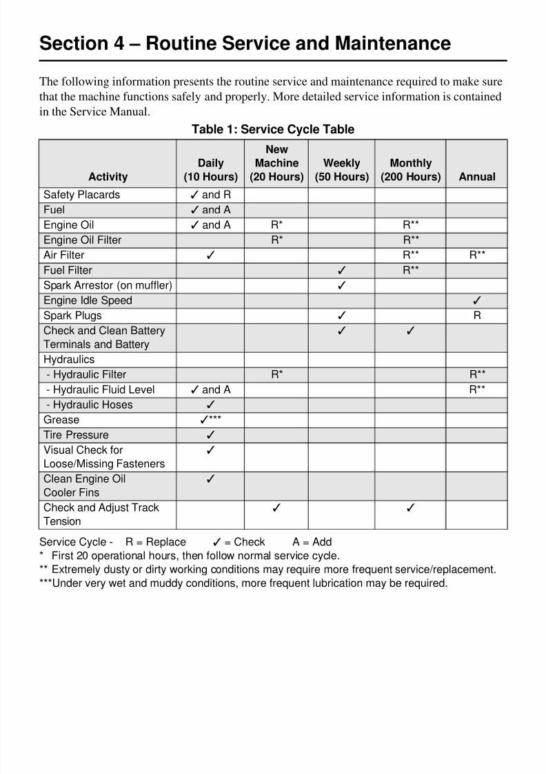
Section 4 – Routine Service and Maintenance
The following information presents the routine service and maintenance required to make sure
that the machine functions safely and properly. More detailed service information is contained
in the Service Manual.
Table 1: Service Cycle Table
Service Cycle - R = Replace ✓ = Check A = Add* First 20 operational hours, then follow normal service cycle.
** Extremely dusty or dirty working conditions may require more frequent service/replacement.
***Under very wet and muddy conditions, more frequent lubrication may be required.
Activity
Daily
(10 Hours)
New
Machine
(20 Hours)
Weekly
(50 Hours)
Monthly
(200 Hours) Annual
Safety Placards ✓ and R
Fuel ✓ and A
Engine Oil ✓ and A R* R**
Engine Oil Filter R* R**
Air Filter ✓ R** R**
Fuel Filter ✓ R**Spark Arrestor (on muffler) ✓
Engine Idle Speed ✓
Spark Plugs ✓ R
Check and Clean Battery
Terminals and Battery
✓ ✓
Hydraulics
- Hydraulic Filter R* R**
- Hydraulic Fluid Level ✓ and A R**
- Hydraulic Hoses ✓Grease ✓***
Tire Pressure ✓
Visual Check for
Loose/Missing Fasteners
✓
Clean Engine Oil
Cooler Fins
✓
Check and Adjust Track
Tension
✓ ✓
8/6/2019 Brute Operator's Manual
http://slidepdf.com/reader/full/brute-operators-manual 54/88
4-2
Routine Service and Maintenance
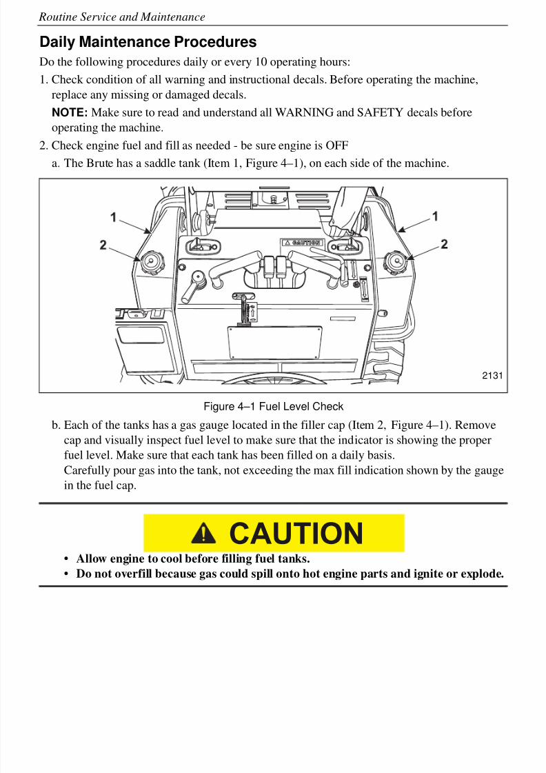
Daily Maintenance Procedures
Do the following procedures daily or every 10 operating hours:
1. Check condition of all warning and instructional decals. Before operating the machine,
replace any missing or damaged decals.
NOTE: Make sure to read and understand all WARNING and SAFETY decals before
operating the machine.
2. Check engine fuel and fill as needed - be sure engine is OFF
a. The Brute has a saddle tank (Item 1, Figure 4–1), on each side of the machine.
Figure 4–1 Fuel Level Check
b. Each of the tanks has a gas gauge located in the filler cap (Item 2, Figure 4–1). Remove
cap and visually inspect fuel level to make sure that the indicator is showing the proper
fuel level. Make sure that each tank has been filled on a daily basis.
Carefully pour gas into the tank, not exceeding the max fill indication shown by the gauge
in the fuel cap.
• Allow engine to cool before filling fuel tanks.
• Do not overfill because gas could spill onto hot engine parts and ignite or explode.
2131
CAUTION
8/6/2019 Brute Operator's Manual
http://slidepdf.com/reader/full/brute-operators-manual 55/88
4-3
Routine Service and Maintenance
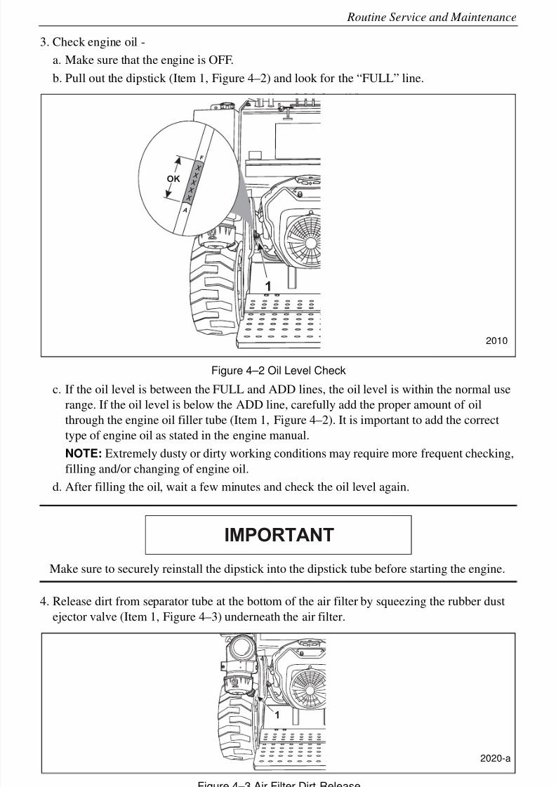
3. Check engine oil -
a. Make sure that the engine is OFF.
b. Pull out the dipstick (Item 1, Figure 4–2) and look for the “FULL” line.
Figure 4–2 Oil Level Check
c. If the oil level is between the FULL and ADD lines, the oil level is within the normal use
range. If the oil level is below the ADD line, carefully add the proper amount of oil
through the engine oil filler tube (Item 1, Figure 4–2). It is important to add the correct
type of engine oil as stated in the engine manual.
NOTE: Extremely dusty or dirty working conditions may require more frequent checking,
filling and/or changing of engine oil.
d. After filling the oil, wait a few minutes and check the oil level again.
Make sure to securely reinstall the dipstick into the dipstick tube before starting the engine.
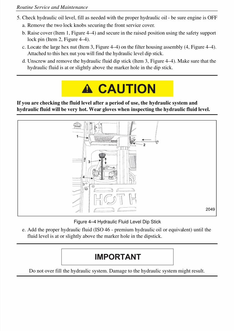
4. Release dirt from separator tube at the bottom of the air filter by squeezing the rubber dust
ejector valve (Item 1, Figure 4–3) underneath the air filter.
Figure 4–3 Air Filter Dirt Release
1
OK
x
x
x
x
x
F
A
2010
IMPORTANT
1
2020-a
8/6/2019 Brute Operator's Manual
http://slidepdf.com/reader/full/brute-operators-manual 56/88
4-4
Routine Service and Maintenance
5. Check hydraulic oil level, fill as needed with the proper hydraulic oil - be sure engine is OFF
a. Remove the two lock knobs securing the front service cover.
b. Raise cover (Item 1, Figure 4–4) and secure in the raised position using the safety support
lock pin (Item 2, Figure 4–4).
c. Locate the large hex nut (Item 3, Figure 4–4) on the filter housing assembly (4, Figure 4–4).
Attached to this hex nut you will find the hydraulic level dip stick.
d. Unscrew and remove the hydraulic fluid dip stick (Item 3, Figure 4–4). Make sure that the
hydraulic fluid is at or slightly above the marker hole in the dip stick.
If you are checking the fluid level after a period of use, the hydraulic system and
hydraulic fluid will be very hot. Wear gloves when inspecting the hydraulic fluid level.
Figure 4–4 Hydraulic Fluid Level Dip Stick
e. Add the proper hydraulic fluid (ISO 46 - premium hydraulic oil or equivalent) until thefluid level is at or slightly above the marker hole in the dipstick.
Do not over fill the hydraulic system. Damage to the hydraulic system might result.
CAUTION
2049
IMPORTANT
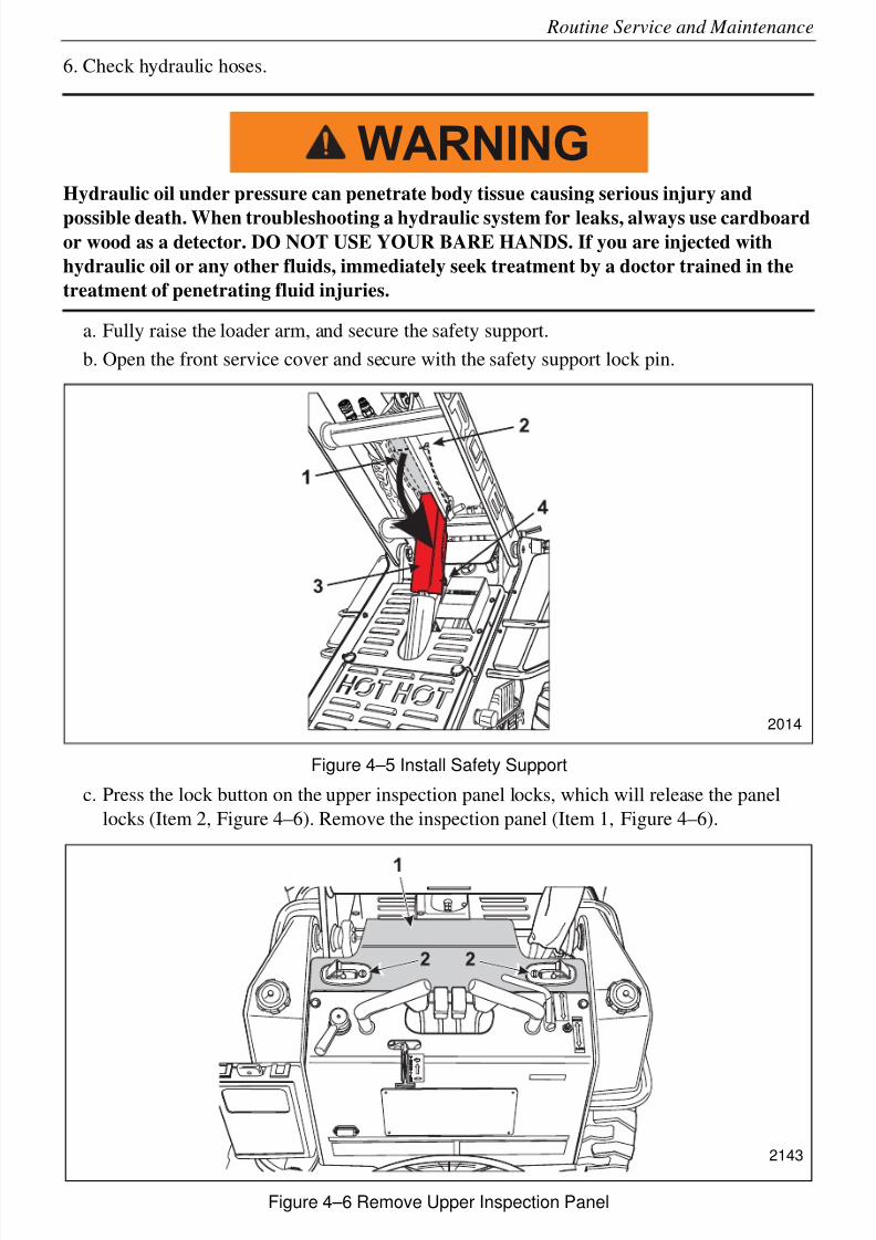
8/6/2019 Brute Operator's Manual
http://slidepdf.com/reader/full/brute-operators-manual 57/88
4-5
Routine Service and Maintenance
6. Check hydraulic hoses.
Hydraulic oil under pressure can penetrate body tissue causing serious injury and
possible death. When troubleshooting a hydraulic system for leaks, always use cardboardor wood as a detector. DO NOT USE YOUR BARE HANDS. If you are injected with
hydraulic oil or any other fluids, immediately seek treatment by a doctor trained in the
treatment of penetrating fluid injuries.
a. Fully raise the loader arm, and secure the safety support.
b. Open the front service cover and secure with the safety support lock pin.
Figure 4–5 Install Safety Support
c. Press the lock button on the upper inspection panel locks, which will release the panel
locks (Item 2, Figure 4–6). Remove the inspection panel (Item 1, Figure 4–6).
Figure 4–6 Remove Upper Inspection Panel
WARNING
2014
2143
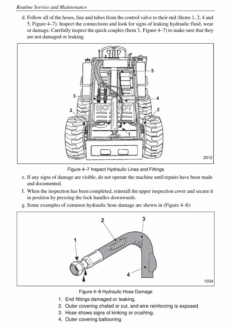
8/6/2019 Brute Operator's Manual
http://slidepdf.com/reader/full/brute-operators-manual 58/88
4-6
Routine Service and Maintenance
d. Follow all of the hoses, line and tubes from the control valve to their end (Items 1, 2, 4 and
5, Figure 4–7). Inspect the connections and look for signs of leaking hydraulic fluid, wear
or damage. Carefully inspect the quick couples (Item 3, Figure 4–7) to make sure that they
are not damaged or leaking.
Figure 4–7 Inspect Hydraulic Lines and Fittings
e. If any signs of damage are visible, do not operate the machine until repairs have been made
and documented.
f. When the inspection has been completed, reinstall the upper inspection cover and secure it
in position by pressing the lock handles downwards.
g. Some examples of common hydraulic hose damage are shown in (Figure 4–8):
Figure 4–8 Hydraulic Hose Damage
1. End fittings damaged or leaking.
2. Outer covering chafed or cut, and wire reinforcing is exposed.
3. Hose shows signs of kinking or crushing.
4. Outer covering ballooning
2012
1
3
4
2
1034
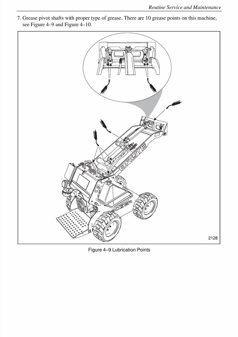
8/6/2019 Brute Operator's Manual
http://slidepdf.com/reader/full/brute-operators-manual 59/88
4-7
Routine Service and Maintenance
7. Grease pivot shafts with proper type of grease. There are 10 grease points on this machine,
see Figure 4–9 and Figure 4–10.
Figure 4–9 Lubrication Points
2128
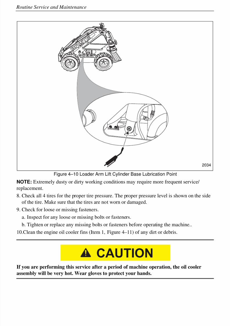
8/6/2019 Brute Operator's Manual
http://slidepdf.com/reader/full/brute-operators-manual 60/88
4-8
Routine Service and Maintenance
Figure 4–10 Loader Arm Lift Cylinder Base Lubrication Point
NOTE: Extremely dusty or dirty working conditions may require more frequent service/
replacement.
8. Check all 4 tires for the proper tire pressure. The proper pressure level is shown on the side
of the tire. Make sure that the tires are not worn or damaged.
9. Check for loose or missing fasteners.
a. Inspect for any loose or missing bolts or fasteners.
b. Tighten or replace any missing bolts or fasteners before operating the machine..
10.Clean the engine oil cooler fins (Item 1, Figure 4–11) of any dirt or debris.
If you are performing this service after a period of machine operation, the oil cooler
assembly will be very hot. Wear gloves to protect your hands.
2034
CAUTION
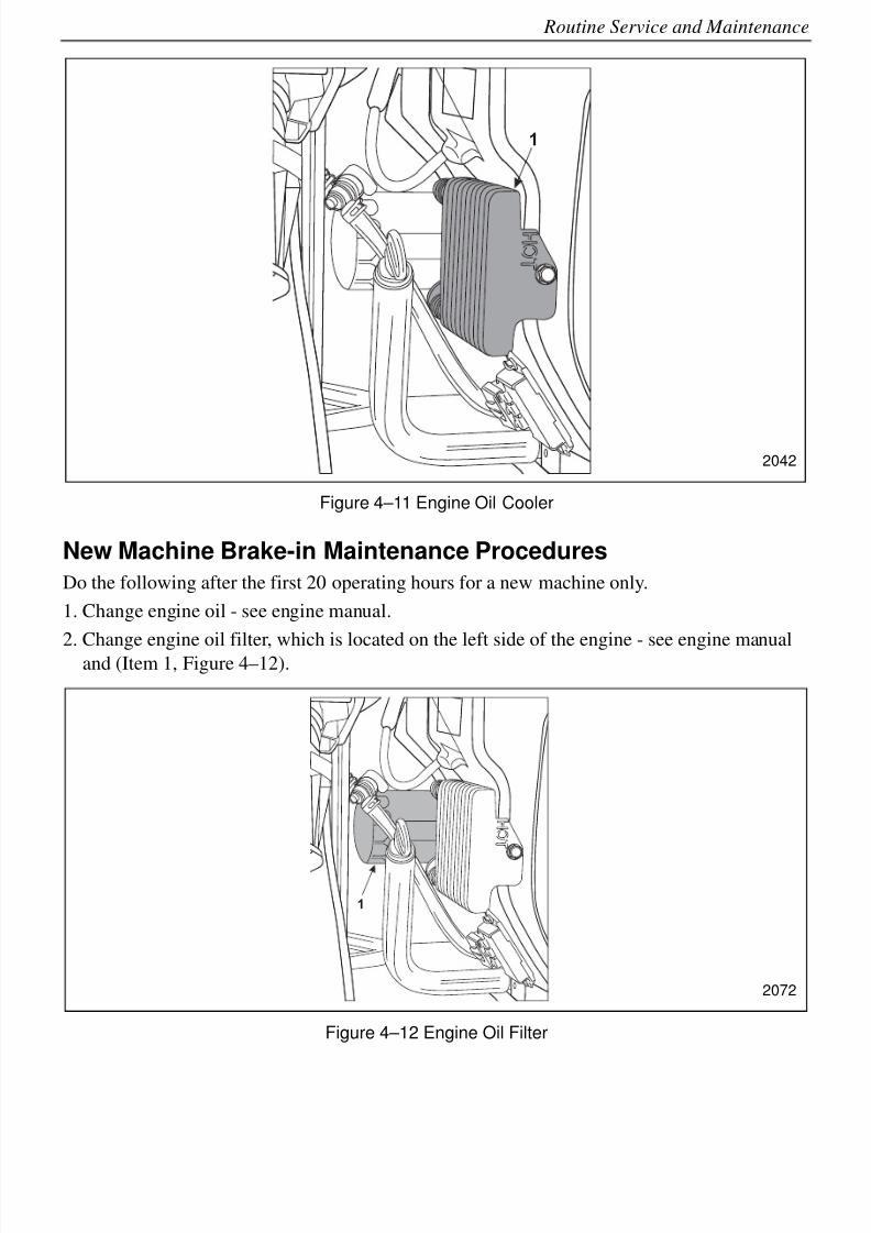
8/6/2019 Brute Operator's Manual
http://slidepdf.com/reader/full/brute-operators-manual 61/88
4-9
Routine Service and Maintenance
Figure 4–11 Engine Oil Cooler
New Machine Brake-in Maintenance Procedures
Do the following after the first 20 operating hours for a new machine only.
1. Change engine oil - see engine manual.
2. Change engine oil filter, which is located on the left side of the engine - see engine manualand (Item 1, Figure 4–12).
Figure 4–12 Engine Oil Filter
1
2042
1
2072
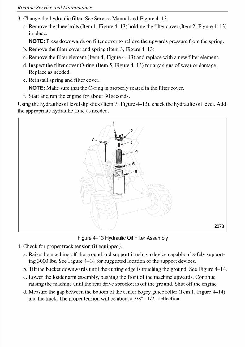
8/6/2019 Brute Operator's Manual
http://slidepdf.com/reader/full/brute-operators-manual 62/88
4-10
Routine Service and Maintenance
3. Change the hydraulic filter. See Service Manual and Figure 4–13.
a. Remove the three bolts (Item 1, Figure 4–13) holding the filter cover (Item 2, Figure 4–13)
in place.
NOTE: Press downwards on filter cover to relieve the upwards pressure from the spring.
b. Remove the filter cover and spring (Item 3, Figure 4–13).
c. Remove the filter element (Item 4, Figure 4–13) and replace with a new filter element.
d. Inspect the filter cover O-ring (Item 5, Figure 4–13) for any signs of wear or damage.
Replace as needed.
e. Reinstall spring and filter cover.
NOTE: Make sure that the O-ring is properly seated in the filter cover.
f. Start and run the engine for about 30 seconds.
Using the hydraulic oil level dip stick (Item 7, Figure 4–13), check the hydraulic oil level. Add
the appropriate hydraulic fluid as needed.
Figure 4–13 Hydraulic Oil Filter Assembly
4. Check for proper track tension (if equipped).
a. Raise the machine off the ground and support it using a device capable of safely support-
ing 3000 lbs. See Figure 4–14 for suggested location of the support devices.
b. Tilt the bucket downwards until the cutting edge is touching the ground. See Figure 4–14.
c. Lower the loader arm assembly, pushing the front of the machine upwards. Continue
raising the machine until the rear drive sprocket is off the ground. Shut off the engine.
d. Measure the gap between the bottom of the center bogey guide roller (Item 1, Figure 4–14)
and the track. The proper tension will be about a 3/8" - 1/2" deflection.
1
2
3
4
5
6
7
2073
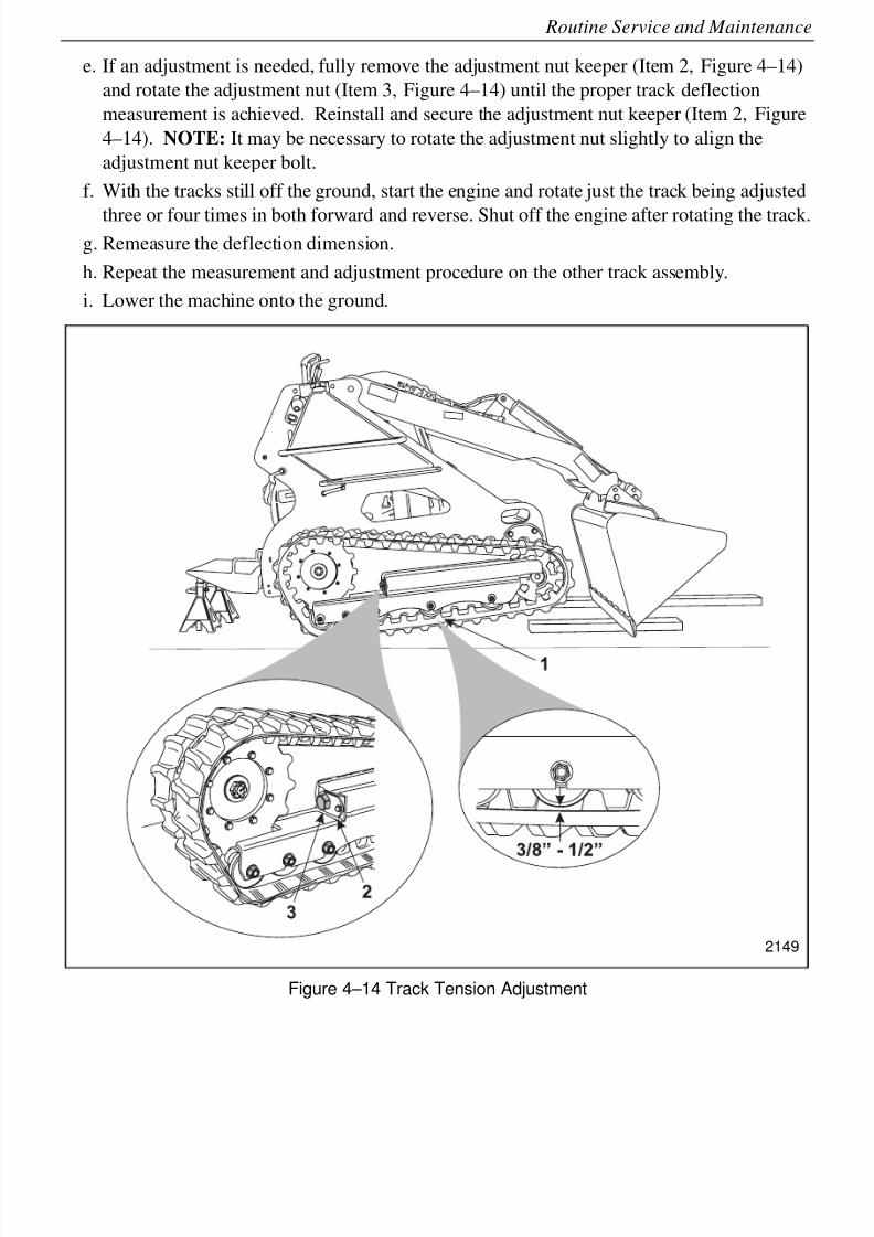
8/6/2019 Brute Operator's Manual
http://slidepdf.com/reader/full/brute-operators-manual 63/88
4-11
Routine Service and Maintenance
e. If an adjustment is needed, fully remove the adjustment nut keeper (Item 2, Figure 4–14)
and rotate the adjustment nut (Item 3, Figure 4–14) until the proper track deflection
measurement is achieved. Reinstall and secure the adjustment nut keeper (Item 2, Figure
4–14). NOTE: It may be necessary to rotate the adjustment nut slightly to align the
adjustment nut keeper bolt.
f. With the tracks still off the ground, start the engine and rotate just the track being adjusted
three or four times in both forward and reverse. Shut off the engine after rotating the track.g. Remeasure the deflection dimension.
h. Repeat the measurement and adjustment procedure on the other track assembly.
i. Lower the machine onto the ground.
Figure 4–14 Track Tension Adjustment
2149
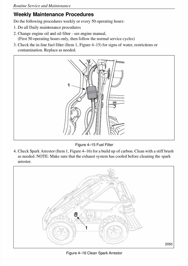
8/6/2019 Brute Operator's Manual
http://slidepdf.com/reader/full/brute-operators-manual 64/88
4-12
Routine Service and Maintenance
Weekly Maintenance Procedures
Do the following procedures weekly or every 50 operating hours:
1. Do all Daily maintenance procedures
2. Change engine oil and oil filter - see engine manual,
(First 50 operating hours only, then follow the normal service cycles)
3. Check the in-line fuel filter (Item 1, Figure 4–15) for signs of water, restrictions orcontamination. Replace as needed.
Figure 4–15 Fuel Filter
4. Check Spark Arrestor (Item 1, Figure 4–16) for a build up of carbon. Clean with a stiff brush
as needed. NOTE: Make sure that the exhaust system has cooled before cleaning the spark
arrestor.
Figure 4–16 Clean Spark Arrestor
1
1
2050
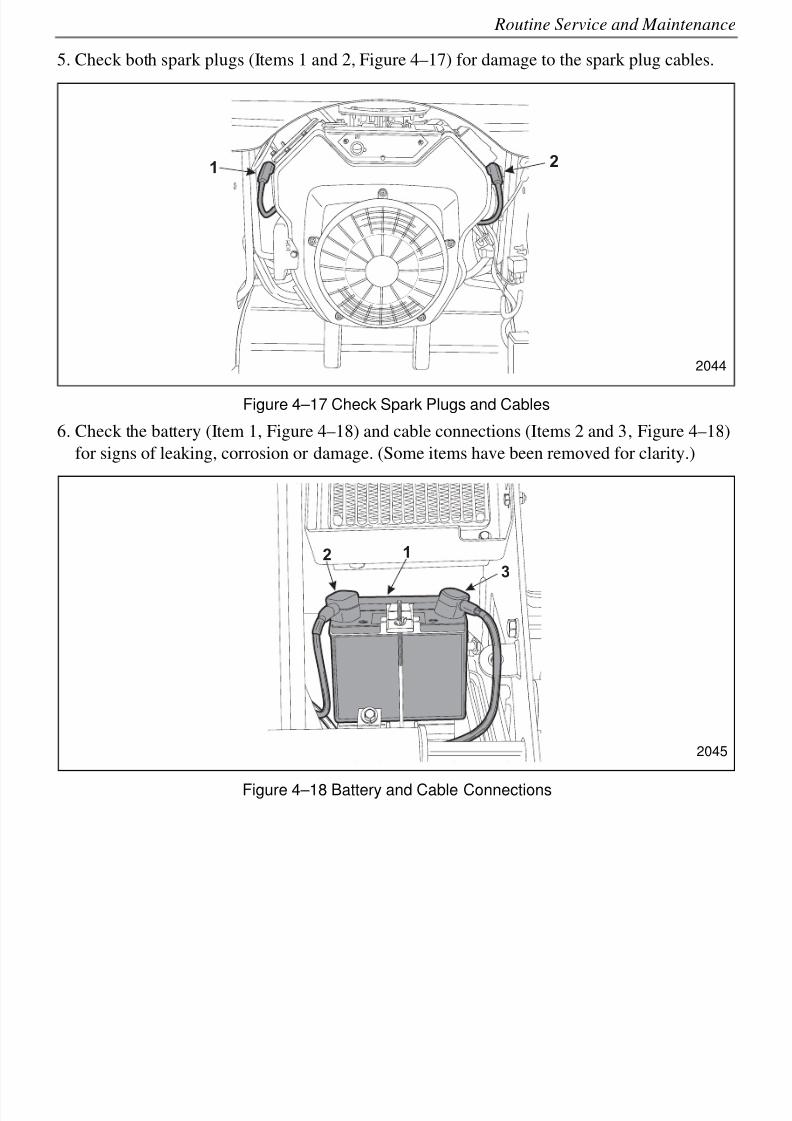
8/6/2019 Brute Operator's Manual
http://slidepdf.com/reader/full/brute-operators-manual 65/88
4-13
Routine Service and Maintenance
5. Check both spark plugs (Items 1 and 2, Figure 4–17) for damage to the spark plug cables.
Figure 4–17 Check Spark Plugs and Cables
6. Check the battery (Item 1, Figure 4–18) and cable connections (Items 2 and 3, Figure 4–18)
for signs of leaking, corrosion or damage. (Some items have been removed for clarity.)
Figure 4–18 Battery and Cable Connections
12
2044
12
3
2045
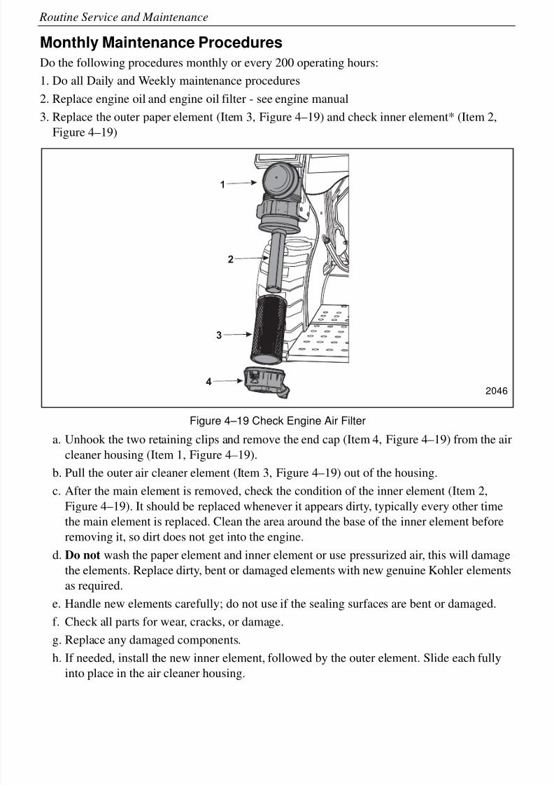
8/6/2019 Brute Operator's Manual
http://slidepdf.com/reader/full/brute-operators-manual 66/88
4-14
Routine Service and Maintenance
Monthly Maintenance Procedures
Do the following procedures monthly or every 200 operating hours:
1. Do all Daily and Weekly maintenance procedures
2. Replace engine oil and engine oil filter - see engine manual
3. Replace the outer paper element (Item 3, Figure 4–19) and check inner element* (Item 2,
Figure 4–19)
Figure 4–19 Check Engine Air Filter
a. Unhook the two retaining clips and remove the end cap (Item 4, Figure 4–19) from the air
cleaner housing (Item 1, Figure 4–19).
b. Pull the outer air cleaner element (Item 3, Figure 4–19) out of the housing.
c. After the main element is removed, check the condition of the inner element (Item 2,
Figure 4–19). It should be replaced whenever it appears dirty, typically every other time
the main element is replaced. Clean the area around the base of the inner element before
removing it, so dirt does not get into the engine.
d. Do not wash the paper element and inner element or use pressurized air, this will damage
the elements. Replace dirty, bent or damaged elements with new genuine Kohler elements
as required.
e. Handle new elements carefully; do not use if the sealing surfaces are bent or damaged.
f. Check all parts for wear, cracks, or damage.
g. Replace any damaged components.
h. If needed, install the new inner element, followed by the outer element. Slide each fully
into place in the air cleaner housing.
1
2
3
42046
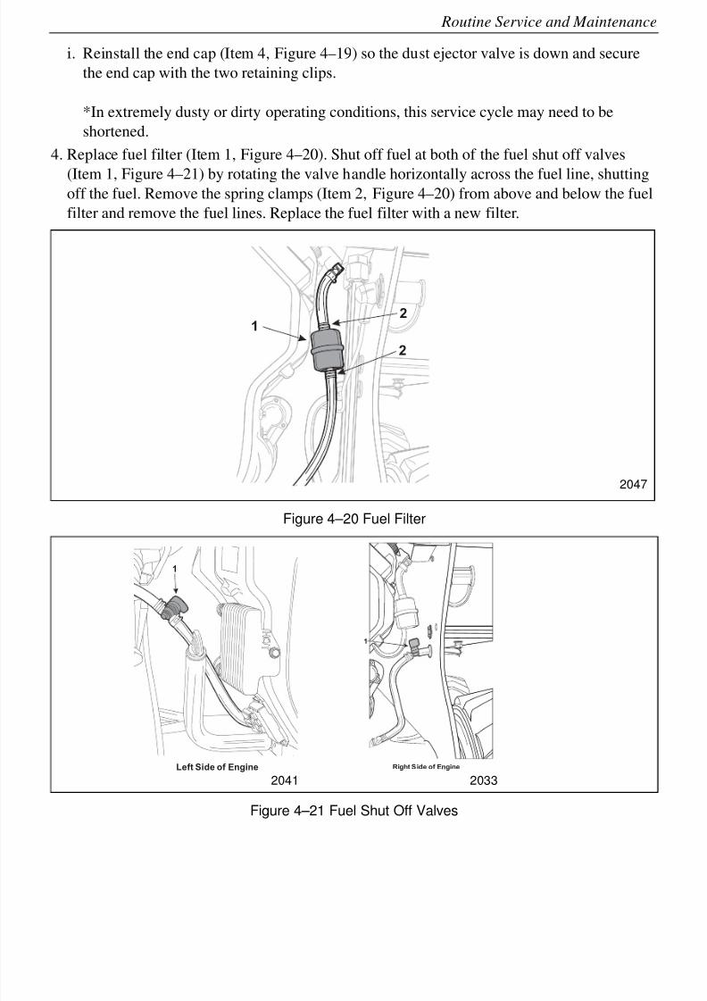
8/6/2019 Brute Operator's Manual
http://slidepdf.com/reader/full/brute-operators-manual 67/88
4-15
Routine Service and Maintenance
i. Reinstall the end cap (Item 4, Figure 4–19) so the dust ejector valve is down and secure
the end cap with the two retaining clips.
*In extremely dusty or dirty operating conditions, this service cycle may need to be
shortened.
4. Replace fuel filter (Item 1, Figure 4–20). Shut off fuel at both of the fuel shut off valves
(Item 1, Figure 4–21) by rotating the valve handle horizontally across the fuel line, shuttingoff the fuel. Remove the spring clamps (Item 2, Figure 4–20) from above and below the fuel
filter and remove the fuel lines. Replace the fuel filter with a new filter.
Figure 4–20 Fuel Filter
Figure 4–21 Fuel Shut Off Valves
1
2
2
2047
1
Left Side of Engine
1
Right S ide of Engine
2041 2033
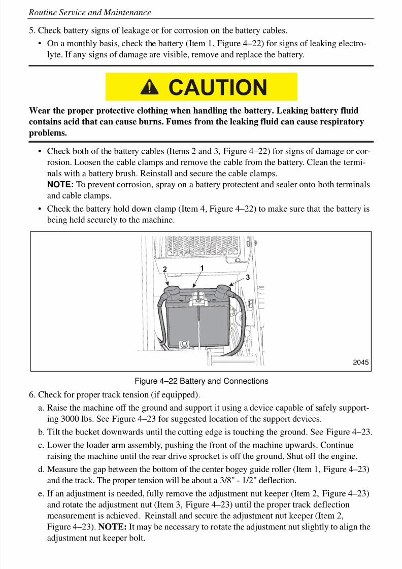
8/6/2019 Brute Operator's Manual
http://slidepdf.com/reader/full/brute-operators-manual 68/88
4-16
Routine Service and Maintenance
5. Check battery signs of leakage or for corrosion on the battery cables.
• On a monthly basis, check the battery (Item 1, Figure 4–22) for signs of leaking electro-
lyte. If any signs of damage are visible, remove and replace the battery.
Wear the proper protective clothing when handling the battery. Leaking battery fluid
contains acid that can cause burns. Fumes from the leaking fluid can cause respiratory
problems.
• Check both of the battery cables (Items 2 and 3, Figure 4–22) for signs of damage or cor-
rosion. Loosen the cable clamps and remove the cable from the battery. Clean the termi-
nals with a battery brush. Reinstall and secure the cable clamps.
NOTE: To prevent corrosion, spray on a battery protectent and sealer onto both terminals
and cable clamps.• Check the battery hold down clamp (Item 4, Figure 4–22) to make sure that the battery is
being held securely to the machine.
Figure 4–22 Battery and Connections
6. Check for proper track tension (if equipped).a. Raise the machine off the ground and support it using a device capable of safely support-
ing 3000 lbs. See Figure 4–23 for suggested location of the support devices.
b. Tilt the bucket downwards until the cutting edge is touching the ground. See Figure 4–23.
c. Lower the loader arm assembly, pushing the front of the machine upwards. Continue
raising the machine until the rear drive sprocket is off the ground. Shut off the engine.
d. Measure the gap between the bottom of the center bogey guide roller (Item 1, Figure 4–23)
and the track. The proper tension will be about a 3/8" - 1/2" deflection.
e. If an adjustment is needed, fully remove the adjustment nut keeper (Item 2, Figure 4–23)
and rotate the adjustment nut (Item 3, Figure 4–23) until the proper track deflection
measurement is achieved. Reinstall and secure the adjustment nut keeper (Item 2,
Figure 4–23). NOTE: It may be necessary to rotate the adjustment nut slightly to align the
adjustment nut keeper bolt.
CAUTION
12
3
2045
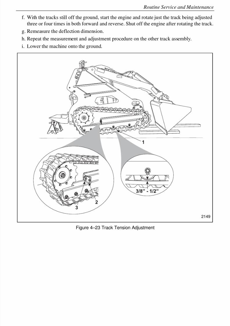
8/6/2019 Brute Operator's Manual
http://slidepdf.com/reader/full/brute-operators-manual 69/88
4-17
Routine Service and Maintenance
f. With the tracks still off the ground, start the engine and rotate just the track being adjusted
three or four times in both forward and reverse. Shut off the engine after rotating the track.
g. Remeasure the deflection dimension.
h. Repeat the measurement and adjustment procedure on the other track assembly.
i. Lower the machine onto the ground.
Figure 4–23 Track Tension Adjustment
2149
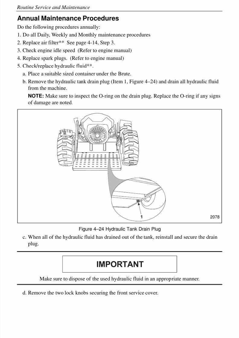
8/6/2019 Brute Operator's Manual
http://slidepdf.com/reader/full/brute-operators-manual 70/88
4-18
Routine Service and Maintenance
Annual Maintenance Procedures
Do the following procedures annually:
1. Do all Daily, Weekly and Monthly maintenance procedures
2. Replace air filter** See page 4-14, Step 3.
3. Check engine idle speed (Refer to engine manual)
4. Replace spark plugs. (Refer to engine manual)5. Check/replace hydraulic fluid**.
a. Place a suitable sized container under the Brute.
b. Remove the hydraulic tank drain plug (Item 1, Figure 4–24) and drain all hydraulic fluid
from the machine.
NOTE: Make sure to inspect the O-ring on the drain plug. Replace the O-ring if any signs
of damage are noted.
Figure 4–24 Hydraulic Tank Drain Plug
c. When all of the hydraulic fluid has drained out of the tank, reinstall and secure the drainplug.
Make sure to dispose of the used hydraulic fluid in an appropriate manner.
d. Remove the two lock knobs securing the front service cover.
1 2078
IMPORTANT
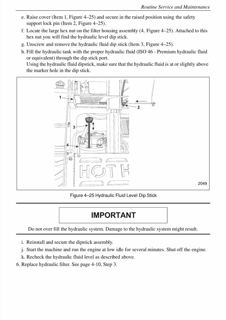
8/6/2019 Brute Operator's Manual
http://slidepdf.com/reader/full/brute-operators-manual 71/88
4-19
Routine Service and Maintenance
e. Raise cover (Item 1, Figure 4–25) and secure in the raised position using the safety
support lock pin (Item 2, Figure 4–25).
f. Locate the large hex nut on the filter housing assembly (4, Figure 4–25). Attached to this
hex nut you will find the hydraulic level dip stick.
g. Unscrew and remove the hydraulic fluid dip stick (Item 3, Figure 4–25).
h. Fill the hydraulic tank with the proper hydraulic fluid (ISO 46 - Premium hydraulic fluid
or equivalent) through the dip stick port.
Using the hydraulic fluid dipstick, make sure that the hydraulic fluid is at or slightly above
the marker hole in the dip stick.
Figure 4–25 Hydraulic Fluid Level Dip Stick
Do not over fill the hydraulic system. Damage to the hydraulic system might result.
i. Reinstall and secure the dipstick assembly.
j. Start the machine and run the engine at low idle for several minutes. Shut off the engine.
k. Recheck the hydraulic fluid level as described above.
6. Replace hydraulic filter. See page 4-10, Step 3.
2049
IMPORTANT
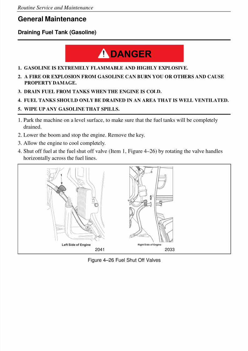
8/6/2019 Brute Operator's Manual
http://slidepdf.com/reader/full/brute-operators-manual 72/88
4-20
Routine Service and Maintenance
General Maintenance
Draining Fuel Tank (Gasoline)
1. GASOLINE IS EXTREMELY FLAMMABLE AND HIGHLY EXPLOSIVE.
2. A FIRE OR EXPLOSION FROM GASOLINE CAN BURN YOU OR OTHERS AND CAUSE
PROPERTY DAMAGE.
3. DRAIN FUEL FROM TANKS WHEN THE ENGINE IS COLD.
4. FUEL TANKS SHOULD ONLY BE DRAINED IN AN AREA THAT IS WELL VENTILATED.
5. WIPE UP ANY GASOLINE THAT SPILLS.
1. Park the machine on a level surface, to make sure that the fuel tanks will be completelydrained.
2. Lower the boom and stop the engine. Remove the key.
3. Allow the engine to cool completely.
4. Shut off fuel at the fuel shut off valve (Item 1, Figure 4–26) by rotating the valve handles
horizontally across the fuel lines.
Figure 4–26 Fuel Shut Off Valves
DANGER
1
Left Side of E
ngine
1
Right S ide of Engine
2041 2033
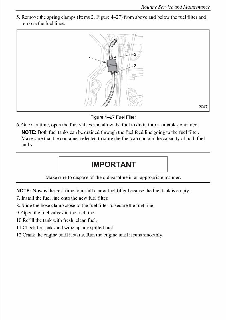
8/6/2019 Brute Operator's Manual
http://slidepdf.com/reader/full/brute-operators-manual 73/88
4-21
Routine Service and Maintenance
5. Remove the spring clamps (Items 2, Figure 4–27) from above and below the fuel filter and
remove the fuel lines.
Figure 4–27 Fuel Filter
6. One at a time, open the fuel valves and allow the fuel to drain into a suitable container.
NOTE: Both fuel tanks can be drained through the fuel feed line going to the fuel filter.
Make sure that the container selected to store the fuel can contain the capacity of both fuel
tanks.
Make sure to dispose of the old gasoline in an appropriate manner.
NOTE: Now is the best time to install a new fuel filter because the fuel tank is empty.
7. Install the fuel line onto the new fuel filter.
8. Slide the hose clamp close to the fuel filter to secure the fuel line.
9. Open the fuel valves in the fuel line.
10.Refill the tank with fresh, clean fuel.
11.Check for leaks and wipe up any spilled fuel.
12.Crank the engine until it starts. Run the engine until it runs smoothly.
1
2
2
2047
IMPORTANT

8/6/2019 Brute Operator's Manual
http://slidepdf.com/reader/full/brute-operators-manual 74/88
4-22
Routine Service and Maintenance
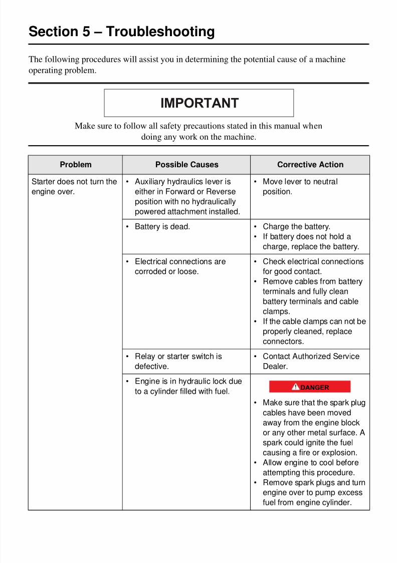
8/6/2019 Brute Operator's Manual
http://slidepdf.com/reader/full/brute-operators-manual 75/88
5-1
Section 5 – Troubleshooting
The following procedures will assist you in determining the potential cause of a machine
operating problem.
Make sure to follow all safety precautions stated in this manual when
doing any work on the machine.
Problem Possible Causes Corrective Action
Starter does not turn the
engine over.
• Auxiliary hydraulics lever is
either in Forward or Reverse
position with no hydraulically
powered attachment installed.
• Move lever to neutral
position.
• Battery is dead. • Charge the battery.
• If battery does not hold a
charge, replace the battery.
• Electrical connections are
corroded or loose.
• Check electrical connections
for good contact.
• Remove cables from battery
terminals and fully clean
battery terminals and cable
clamps.
• If the cable clamps can not be
properly cleaned, replace
connectors.
• Relay or starter switch is
defective.
• Contact Authorized Service
Dealer.
• Engine is in hydraulic lock due
to a cylinder filled with fuel.• Make sure that the spark plug
cables have been moved
away from the engine block
or any other metal surface. A
spark could ignite the fuel
causing a fire or explosion.
• Allow engine to cool before
attempting this procedure.
• Remove spark plugs and turn
engine over to pump excessfuel from engine cylinder.
IMPORTANT
DANGER
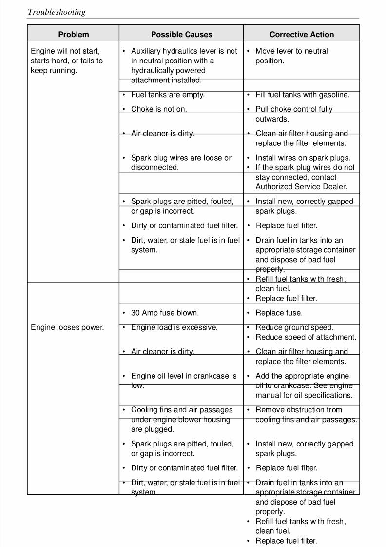
8/6/2019 Brute Operator's Manual
http://slidepdf.com/reader/full/brute-operators-manual 76/88
5-2
Troubleshooting
Engine will not start,
starts hard, or fails to
keep running.
• Auxiliary hydraulics lever is not
in neutral position with a
hydraulically powered
attachment installed.
• Move lever to neutral
position.
• Fuel tanks are empty. • Fill fuel tanks with gasoline.
• Choke is not on. • Pull choke control fully
outwards.
• Air cleaner is dirty. • Clean air filter housing and
replace the filter elements.
• Spark plug wires are loose or
disconnected.
• Install wires on spark plugs.
• If the spark plug wires do not
stay connected, contact
Authorized Service Dealer.
• Spark plugs are pitted, fouled,
or gap is incorrect.
• Install new, correctly gapped
spark plugs.
• Dirty or contaminated fuel filter. • Replace fuel filter.
• Dirt, water, or stale fuel is in fuel
system.
• Drain fuel in tanks into an
appropriate storage container
and dispose of bad fuel
properly.
• Refill fuel tanks with fresh,
clean fuel.• Replace fuel filter.
• 30 Amp fuse blown. • Replace fuse.
Engine looses power. • Engine load is excessive. • Reduce ground speed.
• Reduce speed of attachment.
• Air cleaner is dirty. • Clean air filter housing and
replace the filter elements.
• Engine oil level in crankcase is
low.
• Add the appropriate engine
oil to crankcase. See enginemanual for oil specifications.
• Cooling fins and air passages
under engine blower housing
are plugged.
• Remove obstruction from
cooling fins and air passages.
• Spark plugs are pitted, fouled,
or gap is incorrect.
• Install new, correctly gapped
spark plugs.
• Dirty or contaminated fuel filter. • Replace fuel filter.
• Dirt, water, or stale fuel is in fuel
system.
• Drain fuel in tanks into an
appropriate storage container
and dispose of bad fuel
properly.
• Refill fuel tanks with fresh,
clean fuel.
• Replace fuel filter.
• Spark arrestor plugged. • Clean spark arrestor.
Problem Possible Causes Corrective Action
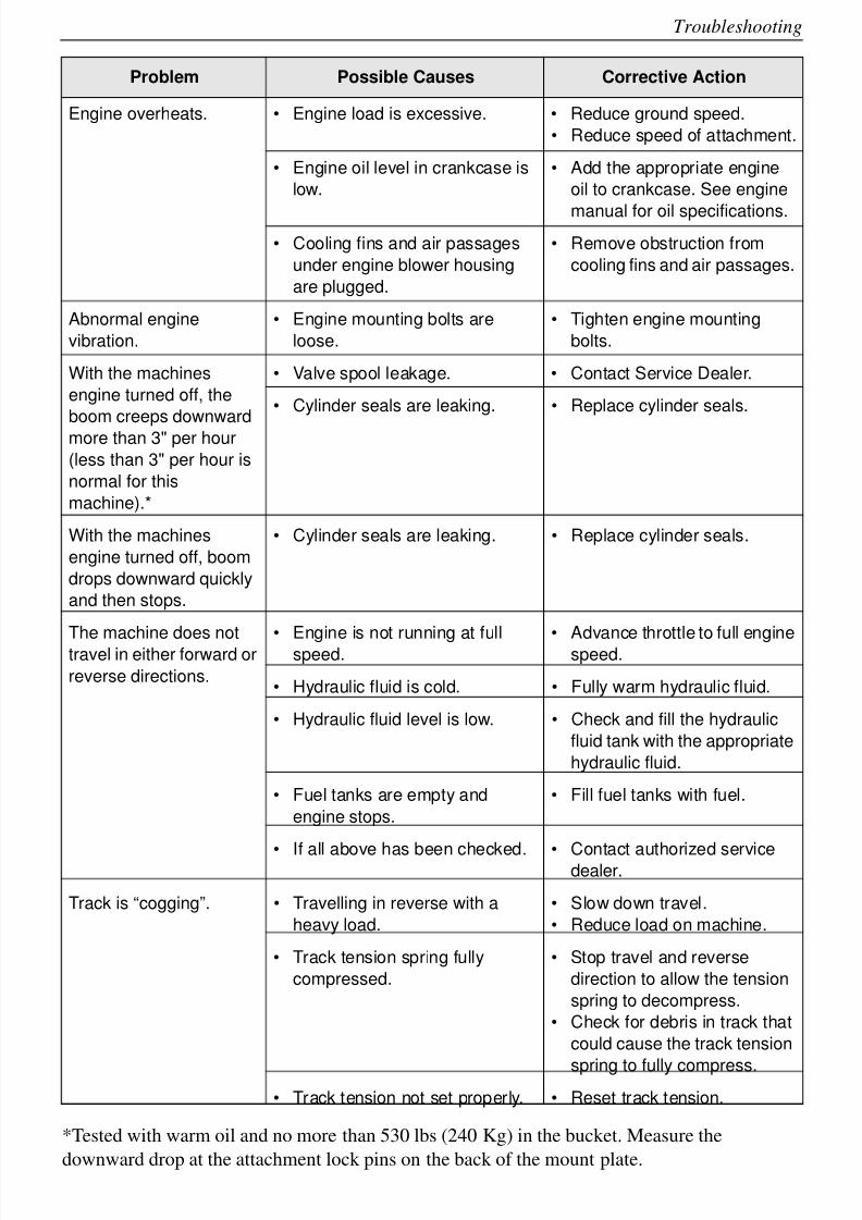
8/6/2019 Brute Operator's Manual
http://slidepdf.com/reader/full/brute-operators-manual 77/88
5-3
Troubleshooting
*Tested with warm oil and no more than 530 lbs (240 Kg) in the bucket. Measure the
downward drop at the attachment lock pins on the back of the mount plate.
Engine overheats. • Engine load is excessive. • Reduce ground speed.
• Reduce speed of attachment.
• Engine oil level in crankcase is
low.
• Add the appropriate engine
oil to crankcase. See engine
manual for oil specifications.
• Cooling fins and air passages
under engine blower housing
are plugged.
• Remove obstruction from
cooling fins and air passages.
Abnormal engine
vibration.
• Engine mounting bolts are
loose.
• Tighten engine mounting
bolts.
With the machines
engine turned off, the
boom creeps downward
more than 3" per hour
(less than 3" per hour is
normal for this
machine).*
• Valve spool leakage. • Contact Service Dealer.
• Cylinder seals are leaking. • Replace cylinder seals.
With the machines
engine turned off, boom
drops downward quickly
and then stops.
• Cylinder seals are leaking. • Replace cylinder seals.
The machine does nottravel in either forward or
reverse directions.
• Engine is not running at fullspeed. • Advance throttle to full enginespeed.
• Hydraulic fluid is cold. • Fully warm hydraulic fluid.
• Hydraulic fluid level is low. • Check and fill the hydraulic
fluid tank with the appropriate
hydraulic fluid.
• Fuel tanks are empty and
engine stops.
• Fill fuel tanks with fuel.
• If all above has been checked. • Contact authorized servicedealer.
Track is “cogging”. • Travelling in reverse with a
heavy load.
• Slow down travel.
• Reduce load on machine.
• Track tension spring fully
compressed.
• Stop travel and reverse
direction to allow the tension
spring to decompress.
• Check for debris in track that
could cause the track tension
spring to fully compress.
• Track tension not set properly. • Reset track tension.
Problem Possible Causes Corrective Action
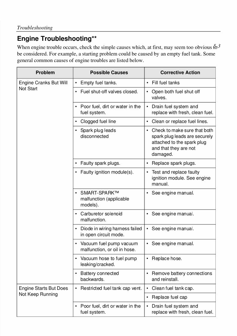
8/6/2019 Brute Operator's Manual
http://slidepdf.com/reader/full/brute-operators-manual 78/88
5-4
Troubleshooting
Engine Troubleshooting**
When engine trouble occurs, check the simple causes which, at first, may seem too obvious to
be considered. For example, a starting problem could be caused by an empty fuel tank. Some
general common causes of engine troubles are listed below.
Problem Possible Causes Corrective Action
Engine Cranks But Will
Not Start
• Empty fuel tanks. • Fill fuel tanks
• Fuel shut-off valves closed. • Open both fuel shut off
valves.
• Poor fuel, dirt or water in the
fuel system.
• Drain fuel system and
replace with fresh, clean fuel.
• Clogged fuel line • Clean or replace fuel lines.
• Spark plug leads
disconnected
• Check to make sure that both
spark plug leads are securelyattached to the spark plug
and that they are not
damaged.
• Faulty spark plugs. • Replace spark plugs.
• Faulty ignition module(s). • Test and replace faulty
ignition module. See engine
manual.
• SMART-SPARK™
malfunction (applicable
models).
• See engine manual.
• Carburetor solenoid
malfunction.
• See engine manual.
• Diode in wiring harness failed
in open circuit mode.
• See engine manual.
• Vacuum fuel pump vacuum
malfunction, or oil in hose.
• See engine manual.
• Vacuum hose to fuel pump
leaking/cracked.
• Replace hose.
• Battery connected
backwards.
• Remove battery connections
and reinstall.
Engine Starts But Does
Not Keep Running
• Restricted fuel tank cap vent. • Clean fuel tank cap.
• Replace fuel cap
• Poor fuel, dirt or water in the
fuel system.
• Drain fuel system and
replace with fresh, clean fuel.
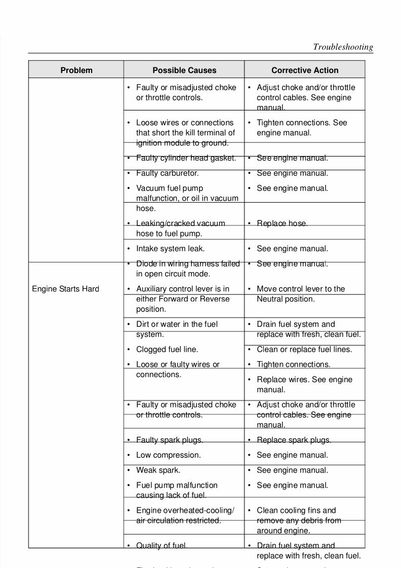
8/6/2019 Brute Operator's Manual
http://slidepdf.com/reader/full/brute-operators-manual 79/88
5-5
Troubleshooting
• Faulty or misadjusted choke
or throttle controls.
• Adjust choke and/or throttle
control cables. See engine
manual.
• Loose wires or connections
that short the kill terminal ofignition module to ground.
• Tighten connections. See
engine manual.
• Faulty cylinder head gasket. • See engine manual.
• Faulty carburetor. • See engine manual.
• Vacuum fuel pump
malfunction, or oil in vacuum
hose.
• See engine manual.
• Leaking/cracked vacuum
hose to fuel pump.
• Replace hose.
• Intake system leak. • See engine manual.
• Diode in wiring harness failed
in open circuit mode.
• See engine manual.
Engine Starts Hard • Auxiliary control lever is in
either Forward or Reverse
position.
• Move control lever to the
Neutral position.
• Dirt or water in the fuel
system.
• Drain fuel system and
replace with fresh, clean fuel.
• Clogged fuel line. • Clean or replace fuel lines.
• Loose or faulty wires or
connections.
• Tighten connections.
• Replace wires. See engine
manual.
• Faulty or misadjusted choke
or throttle controls.
• Adjust choke and/or throttle
control cables. See engine
manual.
• Faulty spark plugs. • Replace spark plugs.
• Low compression. • See engine manual.
• Weak spark. • See engine manual.
• Fuel pump malfunction
causing lack of fuel.
• See engine manual.
• Engine overheated-cooling/
air circulation restricted.
• Clean cooling fins and
remove any debris from
around engine.
• Quality of fuel. • Drain fuel system and
replace with fresh, clean fuel.
• Flywheel key sheared. • See engine manual.
• Intake system leak. • See engine manual.
Problem Possible Causes Corrective Action
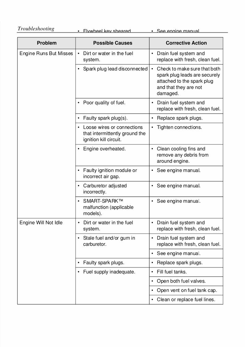
8/6/2019 Brute Operator's Manual
http://slidepdf.com/reader/full/brute-operators-manual 80/88
5-6
Troubleshooting
Engine Runs But Misses • Dirt or water in the fuel
system.
• Drain fuel system and
replace with fresh, clean fuel.
• Spark plug lead disconnected • Check to make sure that both
spark plug leads are securely
attached to the spark plugand that they are not
damaged.
• Poor quality of fuel. • Drain fuel system and
replace with fresh, clean fuel.
• Faulty spark plug(s). • Replace spark plugs.
• Loose wires or connections
that intermittently ground the
ignition kill circuit.
• Tighten connections.
• Engine overheated. • Clean cooling fins and
remove any debris from
around engine.
• Faulty ignition module or
incorrect air gap.
• See engine manual.
• Carburetor adjusted
incorrectly.
• See engine manual.
• SMART-SPARK™malfunction (applicable
models).
• See engine manual.
Engine Will Not Idle • Dirt or water in the fuel
system.
• Drain fuel system and
replace with fresh, clean fuel.
• Stale fuel and/or gum in
carburetor.
• Drain fuel system and
replace with fresh, clean fuel.
• See engine manual.
• Faulty spark plugs. • Replace spark plugs.• Fuel supply inadequate. • Fill fuel tanks.
• Open both fuel valves.
• Open vent on fuel tank cap.
• Clean or replace fuel lines.
Problem Possible Causes Corrective Action
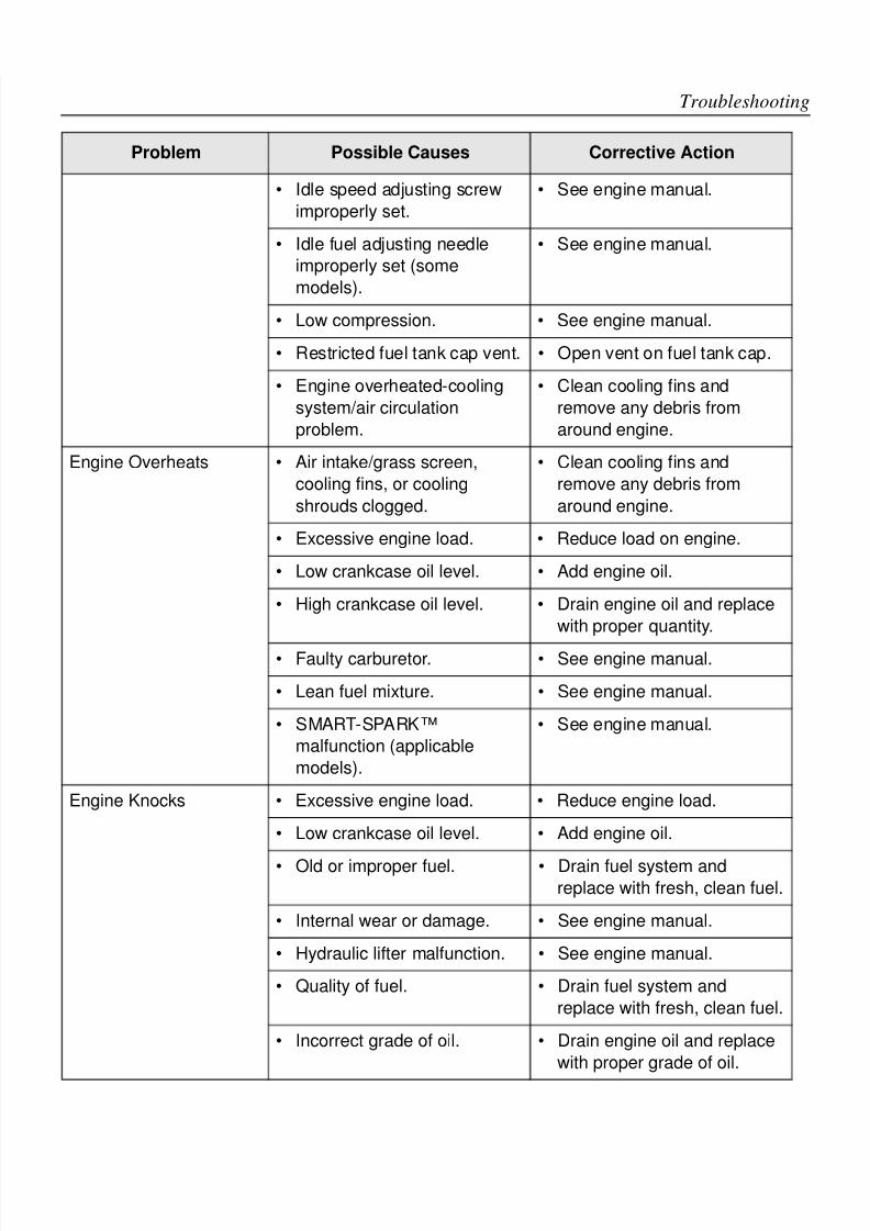
8/6/2019 Brute Operator's Manual
http://slidepdf.com/reader/full/brute-operators-manual 81/88
5-7
Troubleshooting
• Idle speed adjusting screw
improperly set.
• See engine manual.
• Idle fuel adjusting needle
improperly set (some
models).
• See engine manual.
• Low compression. • See engine manual.
• Restricted fuel tank cap vent. • Open vent on fuel tank cap.
• Engine overheated-cooling
system/air circulation
problem.
• Clean cooling fins and
remove any debris from
around engine.
Engine Overheats • Air intake/grass screen,
cooling fins, or cooling
shrouds clogged.
• Clean cooling fins and
remove any debris from
around engine.
• Excessive engine load. • Reduce load on engine.
• Low crankcase oil level. • Add engine oil.
• High crankcase oil level. • Drain engine oil and replace
with proper quantity.
• Faulty carburetor. • See engine manual.
• Lean fuel mixture. • See engine manual.
• SMART-SPARK™malfunction (applicable
models).
• See engine manual.
Engine Knocks • Excessive engine load. • Reduce engine load.
• Low crankcase oil level. • Add engine oil.
• Old or improper fuel. • Drain fuel system and
replace with fresh, clean fuel.
• Internal wear or damage. • See engine manual.
• Hydraulic lifter malfunction. • See engine manual.
• Quality of fuel. • Drain fuel system and
replace with fresh, clean fuel.
• Incorrect grade of oil. • Drain engine oil and replace
with proper grade of oil.
Problem Possible Causes Corrective Action
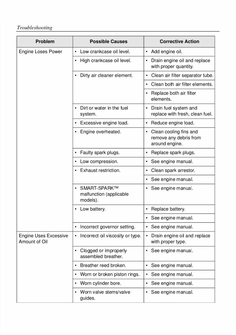
8/6/2019 Brute Operator's Manual
http://slidepdf.com/reader/full/brute-operators-manual 82/88
5-8
Troubleshooting
Engine Loses Power • Low crankcase oil level. • Add engine oil.
• High crankcase oil level. • Drain engine oil and replace
with proper quantity.
• Dirty air cleaner element. • Clean air filter separator tube.
• Clean both air filter elements.
• Replace both air filter
elements.
• Dirt or water in the fuel
system.
• Drain fuel system and
replace with fresh, clean fuel.
• Excessive engine load. • Reduce engine load.
• Engine overheated. • Clean cooling fins and
remove any debris fromaround engine.
• Faulty spark plugs. • Replace spark plugs.
• Low compression. • See engine manual.
• Exhaust restriction. • Clean spark arrestor.
• See engine manual.
• SMART-SPARK™
malfunction (applicablemodels).
• See engine manual.
• Low battery. • Replace battery.
• See engine manual.
• Incorrect governor setting. • See engine manual.
Engine Uses Excessive
Amount of Oil
• Incorrect oil viscosity or type. • Drain engine oil and replace
with proper type.
• Clogged or improperly
assembled breather.
• See engine manual.
• Breather reed broken. • See engine manual.
• Worn or broken piston rings. • See engine manual.
• Worn cylinder bore. • See engine manual.
• Worn valve stems/valve
guides.
• See engine manual.
Problem Possible Causes Corrective Action
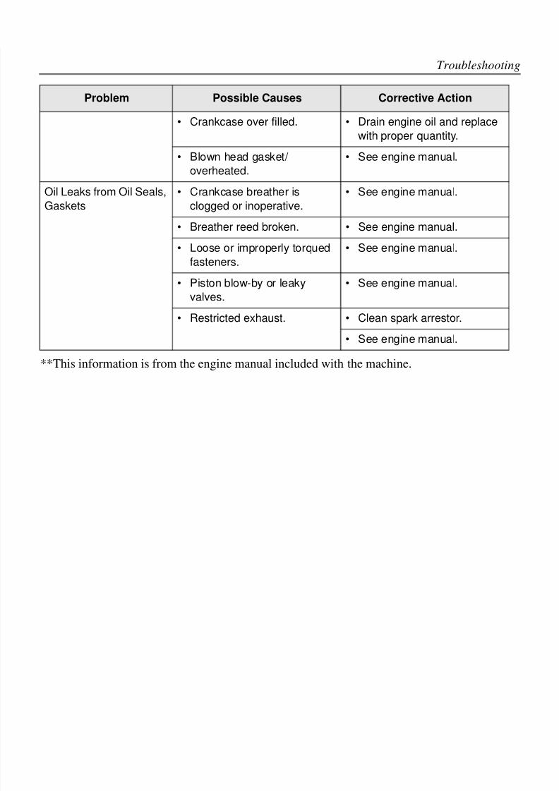
8/6/2019 Brute Operator's Manual
http://slidepdf.com/reader/full/brute-operators-manual 83/88
5-9
Troubleshooting
**This information is from the engine manual included with the machine.
• Crankcase over filled. • Drain engine oil and replace
with proper quantity.
• Blown head gasket/
overheated.
• See engine manual.
Oil Leaks from Oil Seals,
Gaskets
• Crankcase breather is
clogged or inoperative.
• See engine manual.
• Breather reed broken. • See engine manual.
• Loose or improperly torqued
fasteners.
• See engine manual.
• Piston blow-by or leaky
valves.
• See engine manual.
• Restricted exhaust. • Clean spark arrestor.
• See engine manual.
Problem Possible Causes Corrective Action

8/6/2019 Brute Operator's Manual
http://slidepdf.com/reader/full/brute-operators-manual 84/88
5-10
Troubleshooting
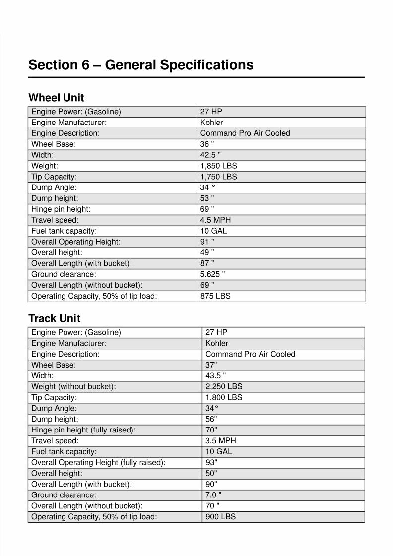
8/6/2019 Brute Operator's Manual
http://slidepdf.com/reader/full/brute-operators-manual 85/88
6-1
Section 6 – General Specifications
Wheel Unit
Track Unit
Engine Power: (Gasoline) 27 HP
Engine Manufacturer: Kohler
Engine Description: Command Pro Air Cooled
Wheel Base: 36 "
Width: 42.5 "
Weight: 1,850 LBS
Tip Capacity: 1,750 LBS
Dump Angle: 34 °
Dump height: 53 "
Hinge pin height: 69 "
Travel speed: 4.5 MPH
Fuel tank capacity: 10 GAL
Overall Operating Height: 91 "
Overall height: 49 "
Overall Length (with bucket): 87 "
Ground clearance: 5.625 "
Overall Length (without bucket): 69 "
Operating Capacity, 50% of tip load: 875 LBS
Engine Power: (Gasoline) 27 HP
Engine Manufacturer: Kohler
Engine Description: Command Pro Air Cooled
Wheel Base: 37"
Width: 43.5 "
Weight (without bucket): 2,250 LBS
Tip Capacity: 1,800 LBS
Dump Angle: 34°
Dump height: 56"
Hinge pin height (fully raised): 70"
Travel speed: 3.5 MPH
Fuel tank capacity: 10 GAL
Overall Operating Height (fully raised): 93"
Overall height: 50"
Overall Length (with bucket): 90"
Ground clearance: 7.0 "
Overall Length (without bucket): 70 "
Operating Capacity, 50% of tip load: 900 LBS
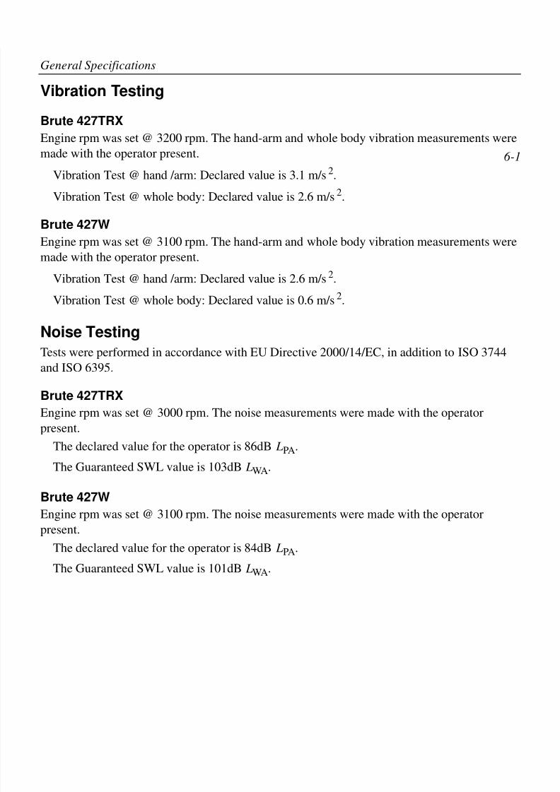
8/6/2019 Brute Operator's Manual
http://slidepdf.com/reader/full/brute-operators-manual 86/88
6-2
General Specifications
Vibration Testing
Brute 427TRX
Engine rpm was set @ 3200 rpm. The hand-arm and whole body vibration measurements were
made with the operator present.
Vibration Test @ hand /arm: Declared value is 3.1 m/s2.
Vibration Test @ whole body: Declared value is 2.6 m/s2.
Brute 427W
Engine rpm was set @ 3100 rpm. The hand-arm and whole body vibration measurements were
made with the operator present.
Vibration Test @ hand /arm: Declared value is 2.6 m/s2.
Vibration Test @ whole body: Declared value is 0.6 m/s2.
Noise Testing
Tests were performed in accordance with EU Directive 2000/14/EC, in addition to ISO 3744
and ISO 6395.
Brute 427TRX
Engine rpm was set @ 3000 rpm. The noise measurements were made with the operator
present.
The declared value for the operator is 86dB LPA.
The Guaranteed SWL value is 103dB LWA.
Brute 427W
Engine rpm was set @ 3100 rpm. The noise measurements were made with the operator
present.
The declared value for the operator is 84dB LPA.
The Guaranteed SWL value is 101dB LWA.

8/6/2019 Brute Operator's Manual
http://slidepdf.com/reader/full/brute-operators-manual 87/88

8/6/2019 Brute Operator's Manual
http://slidepdf.com/reader/full/brute-operators-manual 88/88