
BROYYNINGR - Browning · BROYYNINGR We are proud that you have chosen a ... snow and an infinite...
35
Transcript of BROYYNINGR - Browning · BROYYNINGR We are proud that you have chosen a ... snow and an infinite...


BROYYNINGRWe are proud that you have chosen a
Browning. In its manufacture we have endeav-ored to incorporate the very finest in materialsand craftsmanship, and with just reasonablecare this gun should provide you with manyyears of pleasure and dependable service. If,by any chance, you have any observations tomake regarding its performance or appearance,we hope you will write us immediately.
We would also like to know more about youas a Browning owner and would be grateful ifyou could take but a moment to complete andreturn the marketing survey card found onthe inside back cover.
Thank you.BROWNING
BROWNING New Gun Owner’s RecordKeep this record for future r e f e r e n c e
B r o w n i n g M o d e l .
Gauge..Purchase Price..
Date of Purchase
P l e a s e f i l l o u t a n d m a i l t h e M a r k e t i n g S u r v e y Card at theback of the booklet.
BROWNINGRoute # 1, Morgan, Utah 84050
Distributed in Canada by: 8rowning Arms Co. of Canada, ltd.5350 Ferrier Street, Montreal, Que. H4P 1L9

GAS OPERATED AUTOMATIC SHOTGUNNOMENCLATURE
In conventional gun terminology, the posi-tion and movement of gun parts are describedas they occur with the gun horizontal, innormal firing position; i.e., the muzzle is for-ward or front; butt stock is rearward or rear;trigger is underneath; the rib is on top.
a.
b.
CAUTIONA L W A Y S V I S U A L L Y C H E C KYOUR SHOTGUN - to be certainthat it does not inadvertently containany ammunition. Whenever you pickup a gun, immediately make sure thegun is on safe and the chamber andmagazine are unloaded.A L W A Y S K E E P Y O U R G U N ’ SSAFETY IN THE “ON SAFE” POSI-TION - even if you are certain thegun is unloaded. Check and doublecheck, frequently while you are hunt-ing. Be sure contact with a twig, atumble on slippery terrain, the mo-ment of excitement after a shot, or adozen other seemingly innocent inci-dents have not left you with a gun,“off safe.”Never point a gun you are certainis “on safe” at anything you do notintend to shoot. Safe gun handlingdoes not stop with your gun’s mechan-ical safety. It starts there. Handleyour gun at all times with deep respect
1

and with alert consideration to allwithin its range.
c. ALWAYS KEEP THE MUZZLE OFYOUR GUN POINTED IN A SAFEDIRECTION - even though you arecertain the gun is unloaded and “onsafe.” Never point your gun at any-thing you do not intend to shoot.
d. ALWAYS UNLOAD YOUR SHOT-GUN WHEN NOT IN USE - As asafety precaution it is preferable todisassemble your gun for storage.Store your gun and ammunition sep-arately - beyond the reach of children.
e. DO NOT PUT A 20 GAUGE SHELLIN A 12 GAUGE GUN - if you valueyour gun and yourself. We stronglyrecommend that all shells of differentgauges be stored in completely sep-arate and well-marked containers.NEVER store shells of mixed gaugesin a common container or IN YOURPOCKETS. EXAMINE EVERYSHELL YOU PUT IN YOUR GUN.The most certain way to bulge or rup-ture the finest barrel is to drop a 20gauge shell into a 12 gauge chamber.The 20 gauge shell, unfortunately, willnot fall completely through the barrel;its rim is caught by the FRONT of a12 gauge chamber. Your gun will mis-fire, and under conditions of careless-ness made lethal by haste, a 12 gaugeshell can be loaded behind the 20.You could not deliberately have creat-
2
ed a more serious hazard to your gunand yourself.
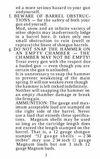
f. BEWARE OF BARREL OBSTRUC-TIONS - for the safety of both yourgun and yourself.Mud, snow and an infinite variety ofother objects may inadvertently lodgein a barrel bore. It takes only onesmall obstruction to ruin (swell orrupture) the finest of shotgun barrels.
g. DO NOT SNAP THE HAMMER ONAN EMPTY CHAMBER - THECHAMBER MAY NOT BE EMPTY!Treat every gun with the respect duea loaded gun - even though you arecertain the gun is unloaded.It is unnecessary to snap the hammerto prevent weakening of the mainspring. It will not weaken even thoughthe hammer is left cocked indefinitely.Neither will snapping the hammer onan empty chamber damage or breakthe firing pin.AMMUNITION: The gauge and max-imum acceptable load are stamped onthe right side of the barrel. Neveruse a load that exceeds these specifica-tions. Magnum shells may be usedso long as the cartridge length doesnot exceed the length stamped on thebarrel. That is, a 12 gauge shotgunstamped “12 gauge shells - 2 3/4inches” may use 2 3/4 inch 12 gaugeMagnum loads but not 3 inch 12gauge Magnum loads.
3

CAUTION: Do not take the meas-urement of an unfired shell to deter-mine the length. An unfired 2 3/4" shell,for example, only measures about 2 1/2". Most shell boxes are stamped as tothe length of the shells they containand some shells are actually individu-ally marked as to their length.The Browning 2000 must be used onlywith the gauge of ammunition stampedon the barrel. The barrel and actionof this shotgun have been made withlarge safety margins over the pressuresdeveloped by established commercialloads. Nevertheless, Browning can as-sume no responsibility for incidentswhich occur through the use of cart-ridges of non-standard dimension orthose developing excessive pressures.
GENERAL OPERATION
This shotgun is gas-operated. A portion ofthe expanding powder gases is bled offthrough gas ports in the barrel and used tooperate the mechanism. During rearwardtravel, the bolt extracts and ejects the spentshell and cocks the hammer. During forwardtravel, a new round is fed from the magazineto the chamber.
This operation is semi-automatic; thetrigger must be released and pulled to fireeach successive shot. After the last shell hasbeen fired, the breech bolt locks open. Thisof course, facilitates speedy reloading.
4

MOUNTING THE BARREL TO ACTIONYour Browning 2000 is packaged and
shipped with the forearm attached to the re-ceiver and magazine tube. In order to installthe barrel it is necessary to remove the fore-arm from the magazine tube and affix theforearm on the barrel before mounting thebarrel to the action. Follow the stens below:
1.
2.
3.
THOROUGHLY CLEAN ALL ANTI-RUST COMPOUND FROM THEBARREL,THE BORE AND OTHERMETAL SURFACES. Remove withany good quality gun oil or gun clean-ing solvent.Unscrew the forearm cap and removethe forearm from the magazine tube.Affix the forearm to the barrel by lo-cating the entire forearm rearward ofthe barrel ring and gently sliding theforearm forward until the barrel ring isseated against the rubber forearm bush-ing (Figure 1). Do not force the rear-ward end of the forearm upward aroundthe barrel as this could split the fore-arm.

4.
5.
Draw the breech bolt rearward so thatit remains locked back. Be sure thesafety is “on safe”.Grasp the butt stock by the pistol gripand anchor the butt end on your hip.With your other hand grasp the fore-arm and barrel and after a final glancethrough the bore to be sure there is nobarrel obstruction, carefully work theforearm down the magazine tube andintroduce the barrel extension into thereceiver (Figure 2).
6

6. As the barrel and forearm are seatedinto final position, be certain the U-shaped cut in the barrel extension(Figure 3) mates fully against the
Fig. 3
barrel guide in the upper inside of thereceiver (Point A, Figure 4). Also
check that the metal forearm tabs inthe rearward end of the forearm (Fig-ure 5) slide into the opposing receiverrecesses (Point B, Figure 4).
7. Screw the forearm cap onto the maga-zine tube. HAND TIGHTEN ONLY.

Never apply a wrench or any kind ofsevere force.Removing the barrel is simply done byreversing the above procedure. If youprefer to store your gun with the ac-tion and barrel separated, it is suggest-ed that the forearm be attached to themagazine tube and receiver. This se-cures your forearm and prevents itfrom possible damage.
CLOSING THE BREECHDo not press the carrier latch and let the
breech bolt ride home under its own force, un-less the bolt is actually feeding a round intothe chamber. It is always advisable, wheneverthe bolt is being closed on an empty chamberor being closed after the barrel has been re-moved from the action, to hook your thumbor finger around the bolt operating handle andlet the bolt ease forward.
CROSS-BOLT SAFETYThe cross bolt safety blocks the trigger
from operating. In the “off safe” or “fire”position a red warning band is visible, on theleft side of the trigger guard_, alerting theshooter of the gun’s ready-to-fire status.
To accommodate left hand shooters, thissafety can be reversed by a gunsmith in amatter of minutes. When reversed, of course,the red warning band will then appear on the
8

right side of the trigger guard. Unlike manyother guns with cross bolt safeties, no extraparts are necessary for this conversion.
LOADINGBE SURE THE MUZZLE IS POINTED
IN A SAFE D I R E C T I O N , A N D T H ESAFETY I§ “ON SAFE.”
The Browning 2 0 0 0 is equipped with thespeed loading system Browning Automaticshotguns are famous for. It is not necessaryto jiggle the first round into the chamber andthen trip the carrier latch (bolt release) toready the first round for firing. Nor is it neces-sary to insert a round into the magazine andthen cycle the bolt to chamber the first round
After being sure the breech bolt is lockedopen, all you do is thumb the first round intothe loading port on the left side of the re-ceiver.. Push this first round forward so thatthe brass head of the shell is about aninch forward of the carrier latch trip (Figure6). Release the shell by withdrawing yourthumb completely out of the loading port andletting the shell slam rearward against the
carrier latch trip. Instantly this round willbe whisked into the chamber ready for firing!
9

(Remember to keep your fingers away fromthe ejection port on the opposite side of thereceiver. The bolt drives forward with forceduring the loading of this first round.)
The second, third and fourth shells to beloaded are then thumbed completely into themagazine. You will not be able to insert thefifth shell you load completely into the maga-zine. This fifth shell (the second shell in line-up for firing) is inserted so that it lays in theloading port with the crimped end protrudingonly partly into the magazine (Figure 7). Be
certain that this shell lays straight and is en-tirely within the loading port. It is held firm-ly in this position and will not fall out orrattle.
This is also true when the plug is installed- the third (last) shell to be loaded (secondin firing sequence) lays visible in the loadingport.
The shellSWITCH LOADS FASTwhich lays visible in the loading
port can be quickly removed, if you want toswitch loads in a hurry. Suppose your 2000 isloaded with duck loads and geese decide to veeryour way. Simply pluck the visible shell fromthe loading port and insert a goose load. Cyclethe bolt. Your chambered duck load will eject,and the goose load will be chambered.
10

FIRINGOnce loaded, all that is necessary to fire
the gun, of course, is to push the safety to the“fire” position and pull the trigger. The firstshell will fire and be ejected. The second willautomatically be chambered. The trigger mustbe released and pulled to fire each succes-sive shot.
THE BREECH REMAINS OPEN after the lastshot has been fired. This allows you to reloadquickly, if you desire to.
BREAKING IN WITH LIGHT LOADSIf the initial shooting of your 12 g a .
B-2000 is done with trap, skeet or light fieldloads, you may experience a few malfunctionsin the first box or two of shells. After thisshort break-in period your B-2000 will oper-ate well with light or heavy loads.
UNLOADINGAs well as speed loading, the Browning
2000 features speed unloading. Before un-loading, BE SURE THE SAFETY IS “ONSAFE” AND THE MUZZLE IS POINTEDIN A SAFE DIRECTION.
The shells in the loading port and maga-zine are unloaded first. Simply ease the shell
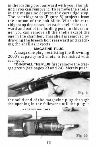
in the loading port outward with your thumbuntil you can remove it. To remove the shellsin the magazine depress the cartridge stop.The cartridge stop (Figure 8) projects fromthe bottom of the bolt slide. With the cart-ridge stop depressed let each shell ride rear-ward and out of the loading port. In this man-ner you can remove all the shells except theone in the chamber. This shell is removed bydrawing the breech bolt rearward and catch-ing the shell as it ejects.
MAGAZINE PLUGA magazine plug, restricting the Browning
2000’s capacity to 3 shots, is furnished witheach gun.
TO INSTALL THE PLUG first remove the trig-ger group (see pages 23 and 24). Merely push
the solid end of the magazine plug throughthe opening in the follower until the plug is
MAGAZINE FOLLOWER
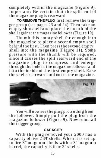
completely within the magazine (Figure 9).Important: Be certain that the split end ofthe magazine plug is rearward.
TO REMOVE THE PLUG first remove the trig-ger group (see pages 23 and 24). Then take anempty shotshell and place the mouth of theshell against the magazine follower (Figure 10).
Thumb this empty shell far enough intothe magazine to place a second empty shellbehind the first. Then press the second emptyshell into the magazine (Figure 11). Somepressure with the thumb will be required,since it causes the split rearward end of themagazine plug to compress and emergethrough the hole in the magazine follower andinto the inside of the first empty shell. Easethe shells rearward and out of the magazine.
You will now see the plug protruding fromthe follower. Simply pull the plug from themagazine follower (Figure 9). Now reinstallthe trigger group.
CAPACITYWith the plug removed your 2000 has a
capacity of five 2 3/4" shells. When it is set upto fire 3" magnum shells with a 3" magnumbarrel, the capacity is four 3" shells.
13

With the plug installed the capacity isreduced to three shells - whether the 2000is set up to fire 2 3/4" shells only or 3” magnumshells.
INTERNAL GAS SYSTEMThe Browning 2000 has a uniquely de-
signed, extremely reliable gas system. It iscompactly contained within the magazinetube. This makes it less accessible to dirt andallows a slim forearm design.
The gas is sealed off so that it cannotblow rearward into the forearm, along theaction bar assembly and toward the actionThe gas is vented forward through the holein the forearm cap.
How often should you strip down the gassystem and clean it? There is no rule ofthumb. It depends somewhat on the type ofammunition you use and how heavily youshoot your gun. Hunters will probably want toclean the system at the season’s end. Trapand skeet shooters will perhaps want to cleanit more frequently It’s a matter of shootingconditions and judgment.
DISMANTLING AND CLEANING THEGAS SYSTEM
Dismantling the gas system is very simple.Make sure the safety is on and draw thebreech bolt rearward until it locks open. Un-screw the forearm cap and remove the barreland forearm.
You will notice the gas piston bar project-
14

ing from each side of the magazine tube (Fig-ure 12). Remove this simply by pushing it
b8Sx:9 _<”from one side and withdrawing it from theother (Figure 13). As you do this hold your
ARE UNDER SPRINGRETAIN THEM AS Y
WITHDRAW GAS Pi
finger or thumb against the gas cylinder plugwhich protrudes slightly from the forward endof the magazine tube (Figure 13). This isnecessary because the gas system is underspring tension.
Now ease the gas system components for-ward out of the magazine tube. Carefullynote the sequence of parts as you withdrawthem from the magazine tube (Figure 14).
(Continued on page 20)
15

BROYYNINGAutomatic 2000 Gas
Operated Shotgun
NOTE: This page contains the sche-matic for the 12 gauge B-2000. F o r
. . .corresponding 20 gaugepar t numbers re fe r to
t h e p a r t s list o n@-I2394 the following page.
lMP0RTANT: W h e n o r d e r i n g p a r t s ,list code number, part name, gauge,model and serial number.
16123&
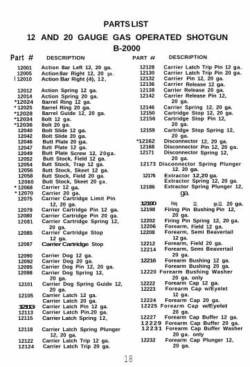
12 AND 20 GAUGE GAS OPERATED SHOTGUNB-2000
Part #1200112005
l 12010
DESCRIPTION
1201212014
*12024* 12025*12028*12034*12036
12040120421204612047120491205212054120561205812060
* 12068* 12070
12075
Action 8ar Left 12, 20 ga.Action 8ar Right 12, 20 ga.Action Bar Right (4), 12,
Action Spring 12 ga.Action Spring 20 ga.8arrel Ring 12 ga.8arrel Ring 20 ga.8arrel Guide 12, 20 ga.8olt 12 ga.8olt 20 ga.Bolt Slide 12 ga.Bolt Slide 20 ga.Butt Plate 20 ga.8utt Plate 12 ga.Butt Plate Screw 12, 20ga.Butt Stock, Field 12 ga.8utt Stock, Trap 12 ga.8utt Stock, Skeet 12 ga.8utt Stock, Field 20 ga.Butt Stock, Skeet 20 ga .Carrier 12 ga.Carrier 20 ga.Carrier Cartridge Limit Pin
12, 20 ga.120791208012081
Carrier Cartridge Pin 12 ga.Carrier Cartridge Pin 20 ga.Carrier Cartridge Spring 12,
20 ga.12085 Carrier Cartridge Stop
12 ga.12087
12090120921209512098
Carrier Cartridge Stop
Carrier Dog 12 ga.Carrier Dog 20 ga.Carrier Dog Pin 12, 20 ga.Carrier Dog Spring 12,
20 ga.12101 Carrier Dog Spring Guide 12,
20 ga.12105
121131211312115
12118
Carrier Latch 12 ga.Carrier Latch 20 ga.Carrier Latch Pin 12 ga.Carrier Latch Pin.20 ga.Carrier Latch Spring 12,
Carrier Latch Spring Plunger12, 20 ga.
12122 Carrier Latch Trip 12 ga.12124 Carrier Latch Trip 20 ga.
PARTS LIST
PART # DESCRIPTION
12128 Carrier Latch Trip Pin 12 ga.12130 Carrier Latch Trip Pin 20 ga.12132 Carrier Pin 12, 20 ga.12136 Carrier Release 12 ga.12138 Carrier Release 20 ga.12142 Carrier Release Pin 12,
20 ga.12146 Carrier Spring 12, 20 ga.12150 Cartridge Stop 12, 20 ga.12156 Cartridge Stop Pin 12,
20 ga.12159 Cartridge Stop Spring 12,
20 ga.*12162 Disconnector 12, 20 ga.
12168 Disconnector Pin 12, 20 ga.12171 Disconnector Spring 12,
20 ga.12173 Disconnector Spring Plunger
12. 20 ga. 12176 Extractor 12,20 ga.
Extractor Spring 12, 20 ga.12186 Extractor Spring Plunger 12,
ga.12190 Firing 12, ga. 12, 20 ga.12198 Firing Pin Bushing Pin 12,
20 ga.12202 Firing Pin Spring 12, 20 ga.12206 Forearm, Field 12 ga.12208 Forearm, Semi Beavertail
1221212214
12 ga.Forearm, Field 20 ga.Forearm, Semi Beavertail
20 ga.12216 Forearm Bushing 12 ga.
Forearm Bushing 20 ga.12220 Forearm Bushing Washer
20 ga. only12222 Forearm Cap 12 ga.12223 Forearm Cap w/Eyelet
12 ga.12224 Forearm Cap 20 ga.12225 Forearm Cap w/Eyelet
20 ga.12227 Forearm Cap Buffer 12 ga.12229 Forearm Cap Buffer 20 ga.12231 Forearm Cap Buffer Washer
20 onlyga.12232 Forearm Cap Plunger 12,
20 ga.
18

PART # DESCRIPTION
12237 Forearm Cap PlungerSpring 12,20 ga.
*12240 Forearm Liner 12 ga.*12242 Forearm Liner 20 ga.* 1 2 2 4 6 Forearm Tabs 12 ga.*12248 Forearm Tabs 20 ga.
12252 Gas Cylinder Plug 12 ga.12254 Gas Cylinder Plug 20 ga.12262 Gas Piston 12 ga.12264 Gas Piston 20 ga.12268 Gas Piston Bar 12 ga.12270 Gas Piston Bar 20 ga.12272 Gas Piston Bar Guide 12 ga.12274 Gas Piston Bar Guide 20 ga.12276 Gas Piston Buffer 12 ga.12278 Gas Piston Buffer 20 ga.12282122841228712289
*12292* 12294
12298122991230212304123O81231012312
Gas Piston Spring 12 ga.Gas Piston Spring 20 ga.Gas Piston Valve 12 ga.Gas Piston Valve 20 ga.Hammer 12 ga.Hammer 20 ga.Hammer Pin 12 ga.Hammer Pin 20 ga.Inertia Piece 12 ga.Inertia Piece 20 ga.Locking Block 12 ga.Locking Block 20 ga.Magazine Adaptor Three
Shot 12, 20 ga.12315 Magazine Base 12 ga.12318 Magazine Base 20 ga.12320 Magazine Base Pin 12 ga.12322 Magazine Base Pin 20 ga.12324 Magazine Follower 12 ga.12326 Magazine Follower 20 ga.12330 Maaazine Spring 12 ga.12332 Magazine Spring 20 ga.
*12336 Magazine Tube 12 ga.*12338 Maaazine Tube 20 ga.12342 Ma&spring-Right or Left
12, 20 ga.12348 Mainspring Guide-Right or
Left 12. 20 ga.12352 Mainspring Pin-Hammer
12 ga.12354 Mainspring P i n - H a m m e r
12356 Mainspring Pin-TriggerGuard 12 ga.
PART #
12358
123601236212366
12370
12374
*l2378
*l2384
1239412396123981240212406
12408
*12415*12417
1242012421124221242412428
*12432*12434
12438124421244512452
12453
12454
12458
1246212464
DESCRIPTION
Mainspring Pin-TriggerGuard 20 ga.
Operating Handle 12 ga.Operating Handle 20 ga.Operating Handle Retainer
Pin 12, 20 ga.Operating Handle Retainer
Pin 12, 20 ga.Operating Handle Retainer
Spring 12, 20 ga.Receiver Assembly 12 ga.
Receiver 12 ga. Field Type 2Receiver Assembly 12 ga.
Trap & SkeetReceiver Assembly 20 ga.
Receiver 20 ga. Field Type 2Receiver Assembly 20 ga.
Receiver Buffer 12 ga.Receiver Buffer 20 ga.Safety Crossbolt 12, 20 ga.Safety Spring 12, 20 ga.Safety Spring Plunger 12,
20 ga.Safety Spring Retaining
Pin 12, 20 ga.Sear 12 ga. Sear 20 ga.Sear Pin 12, 20 ga.Sight Base Front 12, 20 ga.Sight Bead Front 12, 20 ga.Stock Bolt 12, 20 ga.Stock Bolt Washer 12, 20 ga.Trigger 12 ga.Trigger 20 ga.Trigger Pin 12, 20 ga.Trigger Guard 12 ga.Trigger Guard 20 ga.Trigger Guard Retaining Pin
12 ga.Trigger Guard Retaining Pin
20 ga.Trigger Guard Retaining Pin
Bushing 12, 20 ga.Trigger Guard Retaining Pin
Spring 12, 20 ga.Trigger Guard Shield 12 ga.Trigger Guard Shield 20 ga.
I n ‘1977 production, these two parts will be combined to form one integralpart.
I n 1977 production, forearm tabs will be part of one integral piece.M a y be purchased only by holder of valid Federal Firearms license.
*Indicates part must be fitted by our Service Department or Qualified Gunsmith.
19
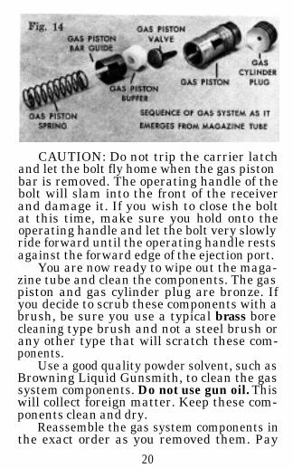
CAUTION: Do not trip the carrier latchand let the bolt fly home when the gas pistonbar is removed. The operating handle of thebolt will slam into the front of the receiverand damage it. If you wish to close the boltat this time, make sure you hold onto theoperating handle and let the bolt very slowlyride forward until the operating handle restsagainst the forward edge of the ejection port.
You are now ready to wipe out the maga-zine tube and clean the components. The gaspiston and gas cylinder plug are bronze. Ifyou decide to scrub these components with abrush, be sure you use a typical brass borecleaning type brush and not a steel brush orany other type that will scratch these com-ponents.
Use a good quality powder solvent, such asBrowning Liquid Gunsmith, to clean the gassystem components. Do not use gun oil. Thiswill collect foreign matter. Keep these com-ponents clean and dry.
Reassemble the gas system components inthe exact order as you removed them. Pay
20

particular attention to lining up the slot inthe gas piston bar guide (A, Figure 15) withthe holes in the gas piston (B, Figure 15) andthe magazine tube (C, Figure 15) so that youcan easily insert the gas piston bar. Be cer-
tain that the slot in the gas piston bar guide(A, Figure 15) is rearward. This is criticalfor proper functioning. Also be certain thatthe aperture in the forward end of the gas
GAS ENTRANCE APER
IN MAGAZINE TUBE

piston is located upward and in alignmentwith the gas entrance aperture in the top ofthe magazine tube (Figure 16). To insurethat you install the gas piston with this aper-ture upward, the slot C in the magazine tubeand the slots A & B in the gas piston andgas piston bar guide are machined off centerIf after installing the gas system in the mag-azine tube, you cannot easily install the gaspiston bar, you have not assembled the com-ponents properly. Remove them and be cer-tain the aperture is located upward. Neverunder any circumstances tap the gas pistonbar with a hammer or other object. If youcannot insert the bar with your fingers, youare not assembling the gas system correctly
Also during assembly be sure the concavesurface of the gas cylinder plug bears againstthe gas piston.
(Of Interest: During disassembly of thegas system you will have noticed the white gaspiston buffer. Buffers are also located in theforearm cap and in the rearward portion ofthe receiver. These act as shock absorbersgreatly cushioning the forceful operation ofthe gas system and the energy it imparts tothe bolt. They help to soften recoil, makingyour 2000 very pleasant to shoot.)
TO SHOOT 3" MAGNUMS
If the barrel of your Browning 2000 ischambered for 2 3/4" shells, all you need toshoot 3” magnum loads is an extra barrelchambered for 3” shells. You do not need topurchase a different action nor alter the gas
22

system in any way. The gas ports in thebarrels differ, so that you can interchange2 3/4" chambered barrels and 3" chamberedbarrels on the same action
NOTE: With the 3 *inch Magnum barrelinstalled the B-2000 is designed to functionreliably with 3 inch Magnum shells Whileno harm can come from shooting 2 3 /4" Magnum Ioads in the 3 inch chambered Magnumbarrel, it is not advised since the ejectormechanism built into the barrel extensionof the 3" barrel to specifically eject 3" cart-r idges is not totally dependabIe upon ejec-tion with the shorter cartridges. Should theshooter not mind an occasional hang up inthe ejector port with the shorter 2 3/4" Mag_num shells he indeed may also use them ifdesired.
DISASSEMBLY OF THE ACTIONPeriodicalIy YOU may wish to completely
disassemble your Browning 2000 for athorough cleaning Your 2000 can be com-pletely stripped down without any tools ex-ceptmg a drive punch or any similar objectwhich wiII enable you to remove the triggerguard retaining pin. Follow the steps below:Be sure your gun is unloaded and on safe.
1. Remove the barrel and forearm anddismantle the gas system as describedon page 17.
2. Hold onto the bolt operating handletrip the carrier latch and softly easethe bolt forward unti1 the operatinghandle rests against the forward part
23

of the receiver. DO NOT LET THEBOLT SLAM FORWARD.
3. Remove the trigger guard retainingpin (Figure 17).
Fig. 17
TRIGGER GUARD RETAINING PIN
4. Draw the bolt rearward about 1 1/2inches (Figure 18).
CARRIER LATCH
24

5. With your other hand trip the carrierlatch, grasp the trigger guard (Figure18) and remove by forcing it slightlyforward before attempting to lift it outof the receiver (Figure 19).
Ease the bolt for-ward again.With the buttstock resting firmlyon a workbench ortable, grasp theaction bar assem-bly and compressthe a c t i o n springseveral inches(Figure 20).Remove the boltoperating handlewith your otherhand. Firm finger
25

pressure removes it easily (Figure 21).
9. To remove the boltand bolt slide easethe action bar as-sembly forward offthe magazine tubewhile depressingthe cartridge stopwith your finger(Figure 22). Thecartridge stop pro-jects from the bot-tom of the boltslide. Particularlynotice how thedouble action barsseparate from thebolt. This will helpyou during reas-sembly later.
26

You can now easily clean all of these com-ponents as well as the inside of the receiver.(See Figure 23.) Again a good solvent is
ACTION SPRINGBOLT S L I D E
CARTRIDGE STOP
recommended. Further disassembly of thetrigger group is not recommended.
NOTE: Do not apply large quantitiesof oil to the trigger group or other areas ofthe action. Excessive oil is not necessary andserves to collect dust and minute particles ofdirt. Excessive oil could also soak into thestock; softening the walnut and loosening thestock. Only a very, very light film of finequality gun oil is needed to protect theseworking parts.
REASSEMBLY OF THE ACTIONFollow the steps below:1. Slide the action spring onto the maga-
zine tube, compress the action springand start the action bar assembly ontothe magazine tube. Grasp the actionbar assembly keeping the springslightly compressed.
2. Assemble the bolt and bolt slide andalign the action bars in their respective
27

recesses in the bolt slide. This is donejust forward of the receiver before thebolt is completely inserted into thereceiver.
Notice that the left (loading port side)action bar enters from the top of the boltslide (Figure 24) while the right action bar
LEFT ACTION BAR ENTERS
BOLT SLIDE FROM TOP
attaches from the bottom (Figure 25). It is
RIGHT ACTION
BAR ENTERS
BOLT SL IDE
FROM BOTTOM
Fig. 25
28
easiest to cant the bolt assembly to the leftand attach the left action bar first, thenrotate the bolt assembly to the right anddownward until the right action bar is en-gaged.
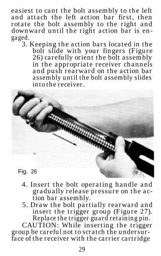
3. Keeping the action bars located in thebolt slide with your fingers (Figure26) carefully orient the bolt assemblyin the appropriate receiver channelsand push rearward on the action barassembly until the bolt assembly slidesinto the receiver.
Fig. 26
4. Insert the bolt operating handle andgradually release pressure on the ac-tion bar assembly.
5. Draw the bolt partially rearward andinsert the trigger group (Figure 27).Replace the trigger guard retaining pin.
CAUTION: While inserting the triggergroup be careful not to scratch the undersur-face of the receiver with the carrier cartridge
29

STOP
stop. (This is the long, slender, unblued pieceof metal which lies alongside the carrier; seeFigure 27.) If you will tip the trigger groupso that you introduce the carrier and the car-rier cartridge stop into the receiver first, youcan easily avoid scratching the receiver.
6. Lock the bolt open.7. Replace the gas system (see pages 19
and 20) and install barrel and forearm.TWO OR MORE: GUNS IN ONE
BY USE OF EXTRA BARRELSUse the same gun for multiple shooting
conditions merely by changing from one bar-rel to another of different choke, length andrib. Barrels of the same gauge are completelyinterchangeable, and no special fitting oraltering of the gas system is required. Thus,by merely buying another barrel, you havethe utility of another gun at a fraction ofthe cost of a new gun . . . a duck gun be-comes a skeet gun or a fine upland gun bythe mere addition of an extra barrel.
30

NOTE: As pointed out earlier, you donot need a complete separate gun to shoot 3”magnums. An extra 3” magnum barrel is allthat is needed. Simply interchange barrels.Altering the gas system is unnecessary. Seepage 22.
NOTE: With the 3 inch Magnum barrelinstalled the B-2000 is designed to functionreliably with 3 inch Magnum shells. Whileno harm can come from shooting 2 3/4" Mag-num loads in the 3 inch chambered Magnumbarrel, it is not advised since the ejectormechanism built into the barrel extension ofthe 3” barrel to specifically eject 3” cart-ridges is not totally dependable upon ejectionwith the shorter cartridges. Should theshooter not mind an occasional hang up inthe ejection port with the shorter 2 3/4" Mag-num shells he indeed may also use them ifdesired.
Please see your Browning dealer forbarrel specifications available.
CLEANING SUGGESTIONS
The correct procedure for cleaning yourshotgun is as follows:
BE CERTAIN YOUR SHOTGUN IS UNLOADED
1. Dismount barrel so that it can becleaned from the breech end.
2. Using a shotgun rod with tip and patchlarge enough for snug fit in bore, in-sert rod and patch in breech end ofbarrel and run back and forth throughbore several times.
31

3. Inspect bore from both ends for leadingby looking through bore toward light.Leading will appear as dull longitudinalstreaks and is usually more predomin-ant in the constriction area of thechoke and just forward of the chamber.
4. Leading is minimal with today’s mod-ern loads. If or when leading shouldbecome heavy, it can be removed witha brass bore brush. Use a good powdersolvent such as Browning Liquid Gun-smith and scrub bore until leading isremoved. To prevent brass bristlesfrom breaking off, the brush should bepushed completely through bore beforebeing withdrawn.
5. After leading has been removed, thebore should be wiped dry and then aslightly oiled patch run through it forpreservation.
6. If the gun has been exposed to muchdust, dirt, mud or water, the actionand gas system should be strippeddown and cleaned as outlined in thisbooklet.
7. Reassemble barrel and wipe all expos-ed metal surfaces with an oiled clothmaking sure to wipe gun clean of allfinger marks where moisture will ac-cumulate.
6. The wood surfaces can also be wipedwith Browning Gun Oil or they can bepolished with any quality furniturewax.
32

SERIAL NUMBER: The serial numberof your Browning 2000 Shotgun is found onthe underside of the receiver, just forwardof the carrier.
CHOKE MARKING
The choke of your barrel is indicated by aclearly defined mark stamped on the righthand side of the barrel. The code for thechoke markings is as follows:Full * Improved Cylinder **_Improved Modified *_ Skeet **SModified * * Cylinder ***
SERVICE OR REPAIR
If your shotgun should require service or repairswe suggest you first contact a local authorizedBrowning Firearms Service Center. Your BrowningSporting Goods dealer can tell you the address ofthe Service Center nearest you or you may call orwrite our Consumer Information Dept. in Morgan,Utah - (801) 876-2711.
Otherwise you may return your shotgun to ourown repair facility for servicing. The address is:
Browning Service Department
Route 4, Box 624-B Tenbrook Road
Arnold, Missouri 63010 (3 14) 287-6800
When returning your shotgun for servicing,please be sure to package it securely in a cardboardcontainer. Send a letter to our Service Departmentclearly describing the trouble experienced and therepairs or alterations desired. If convenient, alsoenclose a copy o f your letter with the gun.
76081033
Printed in U.S.A.

OTHER BROWNING PRODUCTS
ARCHERY EQUIPMENT-Superb-l y e n g i n e e r e d a n d c r a f t e d B r o w n i n g
Bows are avai lable in hunt ing, target
and al l -purpose models to please ex-
perts a n d b e g i n n e r s alike. Com-
p o u n d , t a k e - d o w n a n d s t a n d a r d re-
c u r v e s . M a t c h e d w i t h B r o w n i n g Ar-
r o w s a n d S h o o t i n g A c c e s s o r i e s , f o r
top performance.
BROWNING SPORTING ARMSW o r l d f a m o u s f o r h a n d c r a f t e d q u a l -ity and l i fe t ime dependabi l i ty . Brown-
ing Sporting Arms include a completel ine o f sho tguns , h igh power r i f l es ,
.22 ca l iber r i f les and p is to ls in h ighpower and smal l bore cal ibers .
SPORTSMAN’S KNIVES - wehave knives to dress big game, clean
fish, a n d h a n d l e a n y camp c h o r e .
F o l d i n g K n i v e s , P o c k e t K n i v e s a n d
e v e n a F i l l e t K n i f e w i t h a f i n e c o r k
handle to keep i t af loat. Al l Browning
knives are crafted from special ly heat
t rea ted H igh Carbon Sta in less Stee l
BROWNING SPORTSMAN’SBOOTS 8 CLOTHING - R u g g e db o o t s for every k ind of weather and
t e r r a i n , p l u s h u n t i n g and s h o o t i n gc l o t h i n g t a i l o r e d f o r c o m f o r t , u t i l i t y
and style. Also, hats, shooting glovesand leather be l ts .
GHTWEIGHT CAMPINGEAR - Quality crafted l ightweight
gear with the camper in mind. Choosefrom Prime Northern Duck and Goose
Down, or Dacron® insulated s leepingbags a n d 2 & 3-man r u g g e d , l i g h t -