Brownfield Process: A method for modular product family development ... · Brownfield Process: A...
33
Tampere University of Technology Brownfield Process Citation Pakkanen, J., Juuti, T., & Lehtonen, T. (2016). Brownfield Process: A method for modular product family development aiming for product configuration. DESIGN STUDIES, 45B, 210-241. DOI: 10.1016/j.destud.2016.04.004 Year 2016 Version Publisher's PDF (version of record) Link to publication TUTCRIS Portal (http://www.tut.fi/tutcris) Published in DESIGN STUDIES DOI 10.1016/j.destud.2016.04.004 Copyright (C) 2016 The Authors. Published by Elsevier Ltd. This is an open access article under the CC BY-NC-ND license (http://creativecommons.org/licenses/by-nc-nd/4.0/). Take down policy If you believe that this document breaches copyright, please contact [email protected], and we will remove access to the work immediately and investigate your claim. Download date:20.01.2019
Transcript of Brownfield Process: A method for modular product family development ... · Brownfield Process: A...

Tampere University of Technology
Brownfield Process
CitationPakkanen, J., Juuti, T., & Lehtonen, T. (2016). Brownfield Process: A method for modular product familydevelopment aiming for product configuration. DESIGN STUDIES, 45B, 210-241. DOI:10.1016/j.destud.2016.04.004Year2016
VersionPublisher's PDF (version of record)
Link to publicationTUTCRIS Portal (http://www.tut.fi/tutcris)
Published inDESIGN STUDIES
DOI10.1016/j.destud.2016.04.004
Copyright(C) 2016 The Authors. Published by Elsevier Ltd. This is an open access article under the CC BY-NC-NDlicense (http://creativecommons.org/licenses/by-nc-nd/4.0/).
Take down policyIf you believe that this document breaches copyright, please contact [email protected], and we will remove access tothe work immediately and investigate your claim.
Download date:20.01.2019

�
Corresponding author:
Jarkko Pakkanenjarkko.pakkanen@
tut.fi
ocess: A method for modular
Brownfield Prproduct family development aiming forproduct configurationJarkko Pakkanen, Tero Juuti and Timo Lehtonen, Department of Mechanical
Engineering and Industrial Systems, Tampere University of Technology,
Tampere 33101, Finland
Modularisation, product platforms, product families and product configuration
are efficient product structuring tactics in mass customisation. Industry needs
descriptions of how the engineering should be done in this context. We suggest
that key engineering concepts in this field are partitioning logic, set of modules,
interfaces, architecture and configuration knowledge. A literature review reveals
that methods consider these concepts partly or with different combinations, but
considering all of them is rare. Therefore, a design method known as the
Brownfield Process is presented. The method is applied to an industrial case in
which the aim was rationalisation of existing product variety towards a modular
product family that enables product configuration. We suggest that the method
is valuable in cases with similar goals.
2016 The Authors. Published by Elsevier Ltd. This is an open access article
under the CC BY-NC-ND license (http://creativecommons.org/licenses/by-nc-
nd/4.0/).
Keywords: design method, design process, engineering design, product design,
product development
End users of products can be segmented into different market groups
based on the same kind of expectations related to the products
(Liu, Kiang, & Brusco, 2012). There are companies which are
competing for the share of a single or several market segments. When a com-
pany has to consider customer segments with changing requirements towards
products, the cost effectiveness of offering product variants is one challenge.
This paper studies this kind of environment. Our research background is
familiar with studying companies that operate in projecting business and pro-
duce products in small series (the size of a series can be just one). In these sur-
roundings, the costs of engineering are relatively high in comparison with the
cost of producing the product. The case discussed in Section 2 considers
similar context. Product variety describes the number of different versions
of a product offered by a firm at a single point in time (Randall & Ulrich,
2001). Companies should be able to respond to different customer needs while
keeping their operations profitable. For this challenge, modularisation, prod-
uct platforms, product families and product configuration are suggested
www.elsevier.com/locate/destud
0142-694X Design Studies 45 (2016) 210e241
http://dx.doi.org/10.1016/j.destud.2016.04.004 210� 2016 The Authors. Published by Elsevier Ltd. This is an open access article under the CC BY-NC-ND
license (http://creativecommons.org/licenses/by-nc-nd/4.0/).

Brownfield Process
product development tactics, which are considered as part of the mass cus-
tomisation paradigm (Pine, 1993).
Linking modularisation, product platform and product family development
approaches with product configuration aspects is unusual in design methods,
although these tactics and their importance are highlighted separately for sup-
porting design reuse and enabling several benefits in the business environment
of companies. Consequently, there is a need to study how to structure the key
engineering concepts in this field and how these concepts could be synthesised
in order to support a design situation in which existing product variety should
be rationalised towards a modular product family that supports product
configuration. The focus is on the existing product variety because for example
Oja (2010) describes that the designing of a completely new product is rare in
the manufacturing industry because of the risks.
The paper presents a more advanced method description of our approach to
modular product family development compared to the earlier publication
(Lehtonen, Pakkanen, J€arvenp€a€a, Lanz, & Tuokko, 2011). Considering the
research method, the current situation was analysed first. The original method
description did not consider the most relevant modularisation aspects, though
they were considered in the same industrial case discussed in this paper. This
conclusion was supported by the literature review and also empirical findings
from other projects on modularisation prior to and following the case. As an
outcome of the review, an improved design method for modular product fam-
ily development was described. Validation of the results is based on existing
research and academic publications, in which many of the suggested tools
and approaches have been presented separately and demonstrating the use
of method in a case. The case experiments were originally performed during
2010e2011.
The background of the research context was discussed briefly in this section,
but the literature review is continued in Section 1. A modular product family
development method for configurable products is presented in Section 2. In
Section 3, the conclusions are discussed.
1 Background and motivationThis section focuses on existing research on product family development and
product configuration based on standardisation and modularisation.
1.1 Standardisation and modularisationStandardisation is an important enabler of design reuse and refers to a situa-
tion in which several components are replaced by one component that can
perform the functions of all of them (Perera, Nagarur, & Tabucanon, 1999).
Pahl and Beitz (1996) emphasise that designers should always use readily
211
212
available standard, repeat or bought out parts instead of specially manufac-
tured parts because of cost reasons. Unfortunately, this is not always possible
because of varying customer needs. Victor and Boynton (1998) suggest mod-
ularisation as a product development technique for responding to changing
customer needs which cause pressure in terms of product variety. Ulrich and
Tung (1991) and Pine (1993) present types of modularity including
component-sharing, component-swapping, cut-to-fit, bus, sectional and mix
modularity. Andreasen (2011) explains that modularisation includes the
defining of a modular architecture with module and interface definitions in or-
der to reduce the complexity in operations of a company. Interfaces can be
perceived differently (Parslov & Mortensen, 2015) and effective creation of
variants is enabled by standardised interfaces between varying modules (Cai,
Nee, & Lu, 2009). There are different levels of standardisation related to the
interfaces as well as to components, as Fujimoto (2007) presents. He separates
model specific, company specific and industry standard components and inter-
faces. The categorisation of interfaces to open standard, closed standard, non-
standard and also to frozen or unstable is also presented (Cabigiosu, Zirpoli, &
Camuffo, 2013).
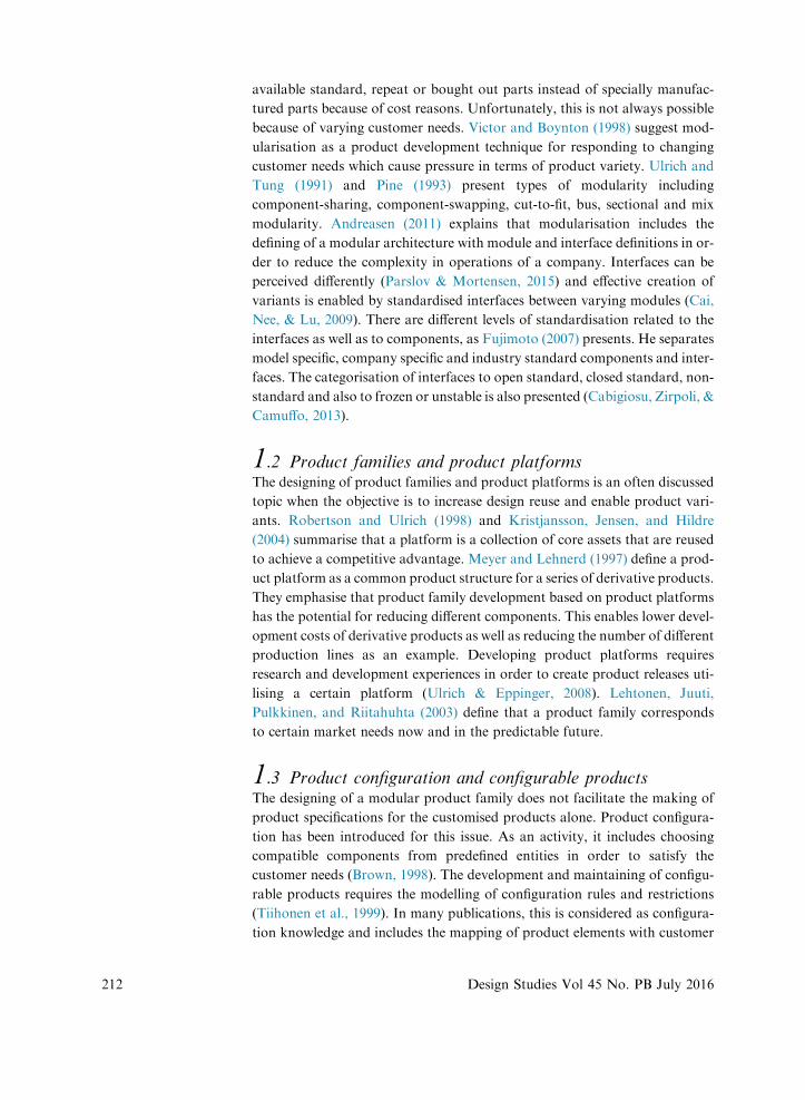
1.2 Product families and product platformsThe designing of product families and product platforms is an often discussed
topic when the objective is to increase design reuse and enable product vari-
ants. Robertson and Ulrich (1998) and Kristjansson, Jensen, and Hildre
(2004) summarise that a platform is a collection of core assets that are reused
to achieve a competitive advantage. Meyer and Lehnerd (1997) define a prod-
uct platform as a common product structure for a series of derivative products.
They emphasise that product family development based on product platforms
has the potential for reducing different components. This enables lower devel-
opment costs of derivative products as well as reducing the number of different
production lines as an example. Developing product platforms requires
research and development experiences in order to create product releases uti-
lising a certain platform (Ulrich & Eppinger, 2008). Lehtonen, Juuti,
Pulkkinen, and Riitahuhta (2003) define that a product family corresponds
to certain market needs now and in the predictable future.
1.3 Product configuration and configurable productsThe designing of a modular product family does not facilitate the making of
product specifications for the customised products alone. Product configura-
tion has been introduced for this issue. As an activity, it includes choosing
compatible components from predefined entities in order to satisfy the
customer needs (Brown, 1998). The development and maintaining of configu-
rable products requires the modelling of configuration rules and restrictions
(Tiihonen et al., 1999). In many publications, this is considered as configura-
tion knowledge and includes the mapping of product elements with customer
Design Studies Vol 45 No. PB July 2016

Brownfield Process
needs. For example, the Unified Modelling Language (UML) and matrix-
based approaches are presented for this task (Bongulielmi, Henseler, Puls, &
Meier, 2001; Felfernig, Friedrich, Jannach, & Zanker, 2002). Configuration
knowledge related to the technical and sales points of view can be used in
the IT systems of a company (Forza & Salvador, 2002). Haug, Hvam, and
Mortensen (2012) explain that the benefits of using an IT-based configurator
include, for example, shorter lead times, improved quality of product specifi-
cations and preservation of knowledge. Hence, product configuration can
bring several benefits if the engineering of a modular product family succeeds.
1.4 Engineering perspective with configurable productsOur aim is to specify such key engineering concepts that provide improved
focus for the engineering work and are essential in designing a modular prod-
uct family that supports product configuration from the product structuring
perspective. Identification of the key engineering concepts is mainly based on
the research performed by Juuti (2008). Product structuring considers identi-
fication of the building blocks in the modular product family, which can be
standard, configurable, partly-configurable or one of a kind. From this
perspective, the reasoning aspects for the modular product family structure
should be highlighted. In this paper, the first key engineering concept is par-
titioning logic, which describes why a certain design is or should be parti-
tioned in a specific way. Customer needs and market considerations
contribute to this element, but the reasons for a certain partitioning may
arise from the supply network or from de facto standards in a certain busi-
ness environment.
We extract the second, third and fourth key engineering concepts as set of
modules, interfaces and architecture. Set of modules includes the definition
of building blocks for creating product variants. We consider that the platform
viewpoints are considered in this concept by defining the type of a building
block: whether a block or a module is used in the every variant or not. Stand-
ardised interfaces are highlighted as the major enabler of efficient defining of
product variants as discussed in Section 1.1. Therefore, we suggest interfaces
as the third key engineering concept. It is also noticed that the consideration
of a modular architecture is beneficial in defining the overall content of a
modular product family (Bruun, Mortensen, & Harlou, 2013; Eilmus,
Gebhardt, Rettberg, & Krause, 2012; Harlou, 2006). Architecture aims to
describe how the modules interact with each other and considers the interface
and layout aspects.
The previous section revealed that focus on product configuration aspects is
important for companies that offer product variants for customers. Consid-
ering the configuration viewpoint as an integrated part of modularisation,
product platform and product family development methods, is exceptional
213

214
though. We treat configuration knowledge as the fifth key engineering concept
because it facilitates the specification of a product variant for the customer,
and this knowledge is reusable for the delivery network.
1.5 Support of existing methods against the businessperspectiveSeveral publications review methods in this field. Jensen and Hildre (2004) pre-
sent that most of the modularisation and platform development methods
consider functionality and technological feasibility. Jose and Tollenaere
(2005) categorise product family development into clustering methods, graph
and matrix methods, mathematical methods, artificial intelligence methods
and genetic algorithms and other heuristic methods. Simpson (2006) suggests
that optimisation approaches are seen in module-based and scale-based family
designing. Jiao, Simpson, and Siddique (2007) explain that product family
development methods are usually platform-based, scale-based or module-
based (configurative) including algorithms and mathematical models.
Salvador (2007) studies the definitions of modularity based on the perspectives
of component commonality, component combinality, function binding, inter-
face standardisation and loose coupling. Gershenson, Khadke, and Lai (2007)
highlight the role of modules and interfaces, drivers for modularity, consid-
ering the life-cycle perspective and analysis of possible benefits in modularisa-
tion and product family designing. Nomaguchi, Askhøj, Madsen, Akai, and
Fujita (2012) present the Design Method Selection Matrix that considers
mainly index-based methods. Okudan Kremer and Gupta (2013) found that
applying different methods resulted in a different number of modules.
Simpson (2004) categorises designing product platforms and product families
into bottom-up (reactive redesign) and top-down (proactive platform) ap-
proaches. Reviewing bottom-up approaches is interesting because of our focus
on rationalising existing products by increasing commonality while enabling
customer variants. In this context, one of the most famous examples is how
Black & Decker redesigned their product line and gained several benefits
(Lehnerd, 1987). Another good example is how a manufacturer of food pro-
cessors redesigned its product line based on consumer perspective with
conjoint analysis and product line simulations (Page & Rosenbaum, 1987).
Ulrich, Randall, Fisher, and Reibstein (1998) state that successful variety stra-
tegies are both market driven and capability driven. Sand, Gu, and Watson
(2002) present a method for redesigning an existing product to enhance the
product modularity based on considering life cycle, product architecture and
functional structures. Farrell and Simpson (2008) present a product platform
portfolio optimisation method that aims to maximise commonality within an
existing product line focussing on market segmentation grid (Meyer &
Lehnerd, 1997). Simpson et al. (2012) present an approach to product family
Design Studies Vol 45 No. PB July 2016
Brownfield Process
design that integrates several tools with qualitative measures and quantitative
data.
Based on the review, we suggest the main categories for modularisation and
product family development methods as function-oriented methods, index-
based methods, optimisation methods and matrix and clustering based
methods.
Functions or function structures in modularisation are considered, for
example, by Erixon (1998), Stone, Wood, and Crawford (2000), and
Dahmus, Gonzalez-Zugasti, and Otto (2001), and Eilmus et al. (2012). The
challenge with these kinds of approaches is that the function-based partition-
ing logic is not a viable approach from the business perspective in all cases, as
Lehtonen (2007) demonstrates.
Indexmethods are seen in the product platformand product family development
publications (Martin & Ishii, 2002; Simpson et al., 2012). Indices are useful in
finding parts in which standardisation and modularisation could bring benefits
asanexample,butadesignmethodshouldalsoguidetheperformingofothertasks
in creating the needed information in themodular product family development.
There are modularisation methods in which optimisation approaches are sug-
gested. Fellini, Papalambros, and Weber (2000) developed a method for quan-
tifying and capturing performance trade-offs for products that share
components based on functional dependencies. Gonzalez-Zugasti, Otto, and
Baker (2000) discuss defining module variants based on a product platform
by focussing on performance and cost objectives. In their approach, product
platform is defined prior to optimising. Gonzalez-Zugasti, Otto, and Baker
(2001) continue with analysing the value of alternative product families. Li
and Azarm (2002) present a method including multi-objective optimisation
in product variant designing that highlights marketing potential. Rai and
Allada (2003) propose a method that is based on creating alternative solutions
and eliminating faulty modules. Optimisation approaches encourage system-
atic designing. According to the studied methods, the industrial applicability
of optimisation methods encounters challenges such as computational ex-
penses, mathematical challenges leading to assumptions and simplifications
and difficulties in valuing non-quantified objectives. Considering our experi-
ences in companies with low volume and partly-configurable product variants,
we have decided to leave optimisation methods outside the scope of the
research objective, but these approaches have potential for future studies.
Matrix and clustering approaches are often seen in publications about modu-
larisation. Applying Design Structure Matrix (DSM) (Steward, 1981) is prob-
ably the most common in this category. Browning (2001) reviews DSM
approaches and considers DSM as a tool for modelling system architectures
215

216
based on components and/or subsystems and their static relations. Also,
Helmer, Yassine, and Meier (2010) suggest a component-based DSM clus-
tering approach for definition of modular product architectures.
Component-based DSM is suggested also in the approach by Simpson et al.
(2012) as a supporting tool for defining differentiation plan and for studying
the interactions of components and sub-systems. Cai et al. (2009) and
Rahmani and Thomson (2009) suggest DSM for analysing relations in product
decomposition and recognition of interfaces. In general, matrices are easy to
use for mapping relations, even though in cases in which the number of ele-
ments is high, matrices might become cumbersome to read and modify. Parti-
tioning is often done using algorithms that help to reorganise the matrix in
order to make architectural decisions. Matrix-based methods are not compre-
hensive alone for holistic modularisation as they do not consider strongly how
to create the relevant information related to the suggested key engineering con-
cepts. Modular product family development needs a case specific target setting
from different perspectives that would explain the reasoning why a product
family should be partitioned in a specific way.
To summarise, there is a lack of design methods of modular product families
that focus on all the suggested key engineering concepts in a redesign situation.
Therefore, objective in the next section is to define a method that considers
these aspects.
2 Modular product family development method sup-porting product configuration
2.1 Overview of Brownfield ProcessFigure 1 presents a method for the rationalisation of existing product variety
towards a modular product family that supports product configuration, which
is named the Brownfield Process (BfP). In our context of product development
in the manufacturing industry, brownfield stands for the reusing of available
assets, and that there are limitations in designing and solutions because of
the existing structures. We suggest that companies which are operating in pro-
jecting business in which products are often customised to fit the customer
needs and where considering the reuse aspects and common architecture is
low, would benefit from applying the method. The first version of BfP was pre-
sented by Lehtonen et al. (2011). This paper defines the approach further as
highlighted in Figure 1 also.
Selected concepts were presented in Section 1.4, but in the following, other key
terms related to BfP are discussed. In designing modular product family con-
cepts, we consider that product structure describes the type of ʻbuilding blocksʼ
the product family consists of. Examples are given in Figure 7. Architecture
describes how the building blocks of product variants are located in the
Design Studies Vol 45 No. PB July 2016

Figure 1 The Brownfield Process (BfP) for rationalisation of existing product variety towards a modular product family that supports product
configuration
Brownfield Process
product family. Compared to product structure, architecture also considers
layout, spatial and interface aspects, whereas product structure is more like
a hierarchical presentation. We separate building blocks of product variants
into generic elements and modules. Considering design hierarchy, generic ele-
ments are upper and therefore the abstract level of actual modules. In the
modular product family, each generic element includes at least one or a set
of alternative solutions which are considered as modules. A module can be
also one of a kind. Whether a generic element can be considered as a platform
element depends on what kind of solutions can actualise it. If a generic element
can be realised with one standard solution that fits all the product variants of a
217

218
product family, then the generic element is similar to the platform element.
Defining generic elements is discussed more in Section 2.4.
BfP includes ten steps and synthesises existing methodological and tool sug-
gestions where applicable. Figure 1 explains the main results of each step
and to which key engineering concept (partitioning logic, set of modules, inter-
faces, architecture and configuration knowledge) the results are related and in
which steps the results of each step are beneficial. BfP begins with defining re-
quirements from the business environment against which the selected existing
product range should be rationalised (Step 1). After that, a preliminary mod-
ule division is defined (Step 2). The positioning of preliminary modules, known
as generic elements, with each other is also studied (Step 3). Understanding of
customer needs is also essential (Step 4). Subsequently, a preliminary product
family content is described (Step 5). Configuration knowledge, including the
relations of generic elements and customer needs, is defined (Step 6). This
step supports the defining of the modular architecture in the next step (Step
7) and the complete configuration knowledge, including actual modules and
variety needs (Step 8). After the modules are defined, the design reasoning
path of each generic element is documented (Step 9). The final step includes
a business impact analysis (Step 10). As an outline for this paper, only the ba-
sics of Step 10 are presented. Applying BfP may involve iteration and custom-
isation. For example, Step 4 can be done after Step 1. Step 2 and 3 are very
dependent on each other and in some cases Step 3 might be done before
Step 2. The methods of BfP are summarised in Table 1. The steps are presented
in Sections 2.3e2.12 in greater detail.
2.2 Case descriptionAlongside the method description, a case in which BfP has been used is dis-
cussed. To respect the sensitive nature of the case, all the details cannot be
explained at length. The case company produces sheet metal processing
equipment comprising loading equipment, portal robots, tables, carriages
and conveyors. Over the years, demand had diversified and numerous de-
vices used for material handling had been developed. The amount of
different alternatives became a challenge for the company. The company
had an excessive number of product solutions which nonetheless fit the
sales-delivery process. The quality of production was rational and good so-
lutions and methods of working were familiar to the company. Many de-
signs were projects for specific customers. This led to situations such as
the development of certain robot models inevitably going on their own
path. Issues were thought about in different devices in similar ways, but
for example customer needs had been examined mainly one device at a
time. The company had earlier experiences of modularisation, but the entire
product range had not been analysed with regard to modularisation and
product configuration. Commonalities had been noticed in products, but a
Design Studies Vol 45 No. PB July 2016

Table 1 Suggested methods in BfP
Primary methods in BfP Alternative methods in BfP
1. Target setting based on businessenvironment
Manual definition using the CompanyStrategic Landscape
Manual definition usingcause-and-effect diagramof benefits of variety withcommonality
2. Generic element model of the modulesystem
Manual planning applying the genericelement definitions
3. Architecture: generic elements andinterfaces
Manual definition using MSPowerpoint, Excel or Visio or similar
4. Target setting based on customerenvironment
Manual definition consideringcustomer needs from the varietyperspective
5. Preliminary product familydescription
Manual definition using the modifiedProduct Family Master Plan
6. Configuration knowledge: genericelements and customer needs
Manual definition using the modifiedK-Matrix
7. Modular architecture: modules andinterfaces
Manual definition applying theprinciples of partly configurableproduct structure, space reservationsand interface standardisation
8. Configuration knowledge: modulevariants and customer needs
Manual definition using the modifiedK-Matrix
9. Product family documentation Manual description using the ProductStructuring Blue Print
10. Business impact analysis Manual estimation using the BIAapproach
Figure 2 Case product: Prima
Power portal robot with a ma-
terial carriage and a conveyor
Brownfield Process
supporting method for the rationalisation of the existing product assortment
was missing. The company also had several unsuccessful rationalisation pro-
jects, which generated learning points and supported the starting of a devel-
opment project throughout the product range. Figure 2 presents the studied
product type.
2.3 Step 1: target setting based on business environmentThe first step focuses on clarifying business objectives related to the designing
of a modular product family. The main results of this step describe areas of the
219

220
business environment in which rationalisation of the existing product range
could bring benefits and what the targets are. Thus this step contributes mainly
to partitioning logic.
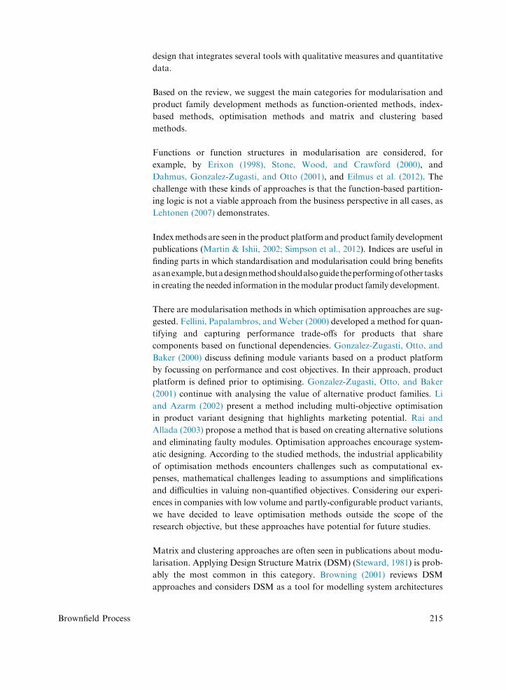
Two frameworks are presented: Company Strategic Landscape (CSL)
(Lehtonen, 2007) and the cause-and-effect diagram about the benefits of com-
monality and variability (Juuti, 2008). A generic CSL framework in Figure 3
presents the main elements of a business environment that relate to the prod-
uct structuring. The aim is that the requirements for rationalisation of product
variety are gone through in a workshop in which the areas of the CSL frame-
work are discussed and defined. The target setting done in the workshop ben-
efits from a multi-disciplinary group of participants because the group
broadens understanding of the drivers for modularisation, and the voice of
different functions can be heard. A specific target might not be relevant to
all the participants in the workshop. Despite this, acknowledgement of these
aspects and following the workshop on target setting can increase understand-
ing about the overall decision making related to a product range. The studied
product range cannot necessarily be optimised from every viewpoint, but
trade-offs are often necessary, as, for example, Eilmus et al. (2012) have
discovered. The product structuring section is considered as a black box in
this step. The goal is to model processes such as product development process,
sales-delivery process and other life cycle phases, value chains the company
wants to operate in and strategy and organisational aspects that influence
product structuring, and to define the targets according to these viewpoints.
The targets can arise from several life phases of the product and from the
different functions of the company.
The cause-and-effect diagram in Figure 4 is suggested for cases in which the
design team has a common understanding of the benefits that are sought after.
This diagram can be used in confirming presumptions about the objectives and
benefits by presenting explicitly the generic benefits from several viewpoints
based on the literature review. This map supports discussion of areas in which
the largest benefits could be achieved. Similar work has been undertaken by
the others. Ramdas (2003) presents a framework for a company’s variety cre-
ation and variety implementation decisions, highlighting revenue and cost as-
pects. Cameron and Crawley (2014) add that commonality enables reduction
of risks, including lower technology risks, higher quality production and
reduced downtime. In Figure 4, the reduction of risks is shown especially in
the possibility to reduce operational waste, time to market and warranty costs.
In the case, the business environment was well defined prior to application of
BfP, and the role of the step was to summarise using Figure 4 why there should
be product development. There was sufficient data available related to activ-
ities and products prior to this step. The target was defined without the partic-
ipation of researchers. The main goal was to reduce operating expenses by
Design Studies Vol 45 No. PB July 2016
Figure 3 Company Strategic Landscape (CSL) framework (Lehtonen, 2007)
Brownfield Process
increasing reuse by defining a common architecture (product family) with
common modules for the studied product type. The product family should
enable use of the same modules in different product variants for customers
where possible. Removing of the existing variants which do not add customer
value and do not support long-term development or production was also
highlighted.
2.4 Step 2: generic element model of the module systemThe objective of the step is to define the ideas of generic elements that could be
basic building blocks, preliminary modules, for the product family in a solu-
tion neutral level based on the existing product variety. Thus, of the five key
engineering concepts, this step focuses mainly on the set of modules. A generic
element contains all that is required in fulfilling one variation need and it
should be possible to realise the element technically as a unit. The aim is
that the generic element division divides the product in sections that encapsu-
late the effect of customer variations.
The defining of generic elements starts with setting up generic (applies to all
variants) list of functionalities and requirements e.g. transformations that
the customer wishes to achieve with the product. The next step is to consider
all the items in the list as technical units (the actual technical realisation is not
considered at this phase). Therefore, the generic elements are abstract in this
sense. Then the existing product structure is taken under consideration by dis-
cussing possibility (in principle) to partition it such way, that there will be tech-
nical units corresponding with the generic elements.
221

Figure 4 Benefits of variety with commonality (Juuti, 2008)
222
Figure 5 presents an example from the case in which the old solutions are
sorted according to the generic element proposals. Originally the summary
of existing solutions was made by the project manager. In the case, the generic
elements were defined in a brainstorming session, in which personnel from
Design Studies Vol 45 No. PB July 2016

Brownfield Process
sales, product development and mechanical, electrical and software engineer-
ing participated. The researcher also participated in this step as a facilitator of
the single day workshop and as a maker of the synthesis, and hence the hand of
the researcher is visible in the results. At first, the participants worked individ-
ually to define their suggestions for generic elements. A common session was
organised subsequently in which the participants formed pairs and analysed
their suggestions and tried to find a common understanding. Five different
proposals for a generic element model were defined. These were analysed in
a common session by the same group. Distinctions were considered beneficial
because the proposals included different views for the same goal. A model,
which included all the different elements presented, was drawn on the white
board and included 37 generic elements and it was noted that some of the el-
ements, such as software elements, needed further dividing. Eventually, 12
different software elements were recognised. Then it was found that the pro-
posed generic element model could not completely fulfil the business targets
and another new suggestion was defined. This suggestion included fewer
than 20 elements, and this was found to be too little. Finally, a combined
model accepted by all the participants was defined including tens of elements.
Some generic elements are listed in Figure 6.
The restrictions of technology may cause that there is no plausible realisation
for some generic elements. Then the generic element needs to be defined differ-
ently. The generic element model that is defined after iterations is a concept for
the modular structure of the product family describing how the partitioning
will be realised. Therefore, every generic element is a concept of a module or
(as more often) set of modules.
In the defining of generic elements, similarity between the generic elements
should be considered. If generic element proposals have many similarities
and redundancies related to their realisation, defining of only one generic
element should be considered. If generic elements that have much commonal-
ity with each other are approved of as separate, there is a risk of unnecessary
variation.
2.5 Step 3: architecture: generic elements and interfacesArchitecture is understood as a layout scheme of generic elements and their in-
terfaces. The defining of architecture is started by thinking how the generic el-
ements are positioned in a typical product. Generic elements that have
interfaces with each other have to be identified, because this is a starting point
for defining standardised interfaces within modules. Because accurately de-
signed modules describing the final structure of the modular product family
not likely to be available at this step, traditional office software such as Micro-
soft PowerPoint, Visio or Excel can be used for visualising the architecture. An
example is given in Figure 9.
223

Figure 5 Analysis of the existing product range in order to identify generic elements
224
In the case, the architecture was illustrated using a two-dimensional layout
figure whose purpose was to clarify the same understanding of the elements
and their relations for the design group. This was done by the project manager
in the company. When considering the five key engineering concepts, this step
considers architecture, set of modules and interfaces on a generic level.
2.6 Step 4: target setting based on customer environmentAnalysing the customer environment is important if the company wants to
change its operating mode from project-specific solutions to configurable
product delivery with predefined modular solutions. Formalised customer
needs are required in the defining of configuration knowledge, which explains
what kind of product will be delivered to the customer with certain needs. If all
the needs cannot be described formally, the part which these requirements
relate to can be left outside the configuration activity, which is based on the
predefined modules. When designing a product family based on existing prod-
ucts, these products have been delivered against specific customer needs. We
presume that the basic requirements that the products must fulfil are known
within the company and thus the focus should be on clarifying the reasons
which cause pressure on variants.
Design Studies Vol 45 No. PB July 2016

Figure 6 Sample of the preliminary product family description and reasoning
Brownfield Process
Customer needs are clarified by using an approach that has a background in
defining a product structure for a truck by configuring (Lehtonen, 2007). In
the sales material of a truck, it is seen how a configurable product can be pre-
sented to a customer. Product options are well defined and their suggested use
case examples are stated. This kind of product philosophical approach is
adapted in this step and therefore is not a unique approach. The need for var-
iants is discussed from the customer viewpoint; what he/she wants to do with a
product. The idea is to define by answering from which configuration ques-
tions from the customer perspective the most suitable options for a product
variant can be selected.
In the case, the customer environment was studied in a one day workshop,
which was facilitated by the researcher. The participants were challenged to
define the main questions that through answering help to define a product
variant for the customer. The contribution of sales was significant. The
main customer requirement groups and more detailed optional require-
ments and ways of working were also identified. In the truck case, we
noticed that the main configuration questions related to the rate of use, ca-
pacity, use environment and preference topics. Although the case is
different to the truck example, the main topics of the identified configura-
tion questions were similar to a high degree. The configuration questions
related, for example, to options of sheet size, material type to be handled,
automation level, factory layout and production process type, as shown in
Figure 6.
225
226
This step contributes mainly to the partitioning logic because the results of this
step are essential in the decision making related to the content of the modular
product family. The purpose is to define a minimum number of modules which
fulfil the variety needs in later steps of BfP.
2.7 Step 5: preliminary product family descriptionThe aim of the step is to make a preliminary description of the product family
by applying a modified version of the Product Family Master Plan (PFMP)
(Harlou, 2006) as a guiding framework. PFMP provides an object-oriented
modelling formalism for product families and highlights customer, engineer-
ing and part views. Research on Generic Bill of Materials (Callahan, 2006;
Hegge & Wortmann, 1991; Jiao, Tseng, Ma, & Zou, 2014) is closely related
to PFMP. These approaches aim to enable the defining of variants with a min-
imum number of data in IT systems. Compared to PFMP, the studied Generic
Bill of Materials approaches highlight product structure issues in the models
but the presenting of reasoning chains for the source of variation is often
missing and consequently we adapt PFMP in this step. Such a detailed
approach as in the original PFMP is not used in BfP. We utilise the idea of
studying customer, engineering and part views and the relations between these
as a base for defining preliminary product family structure in a workshop envi-
ronment. In BfP, the engineering view includes generic elements (results of
Step 2), the customer view includes customer needs producing the need for var-
iants (results of Step 4), and the part view includes parts and assemblies. The
application of these views is discussed using our case. Similarities are found
also in the Domain Theory (Andreasen, 2011) in which activity, organ and
part domains are analysed in order to support reasoning backwards from
the wanted behaviour to a concrete structure of a product. Different types
of generic elements and possibilities for standardisation are discussed in this
step. This step contributes mainly to partitioning logic, set of modules and
configuration knowledge of the five key engineering concepts.
In the case, the preliminary product family description was drawn on the white
board in the single day workshop held at the company. The workshop was
facilitated by the researcher. During the day, the result was defined to an
acceptable extent and it enabled moving to the next phase. Figure 6 presents
a sample of the case. First, generic elements were listed in the middle of the
white board and customer needs on the left hand side. The right hand side
was reserved for parts and assemblies related to the generic elements. Rela-
tions between the customer needs and the generic elements were discussed as
well as relations between the generic elements and the parts and assemblies.
The red arrows (in the web version) stand for examples of the relations be-
tween the different views in Figure 6. The number of parts can multiply quickly
in this view. Therefore, not all of them were described in the model during the
workshop, but making the description supported discussions on the
Design Studies Vol 45 No. PB July 2016

Brownfield Process
preliminary formalisation of the product family. The description done in the
workshop facilitated recognition and the stating of uncertainties related to
the product family and finding ideas for the rationalisation. The design team
mapped out concrete solutions which related to specific generic elements.
Also, an overall picture of the generic elements and the existing concrete solu-
tions and their 3D drawings were studied. This facilitated discussion on the
necessary variants and potential for the standardisation of the parts and
assemblies.
Generic elements which have no relation to any customer needs related to vari-
ability are a potential for standardisation, whereas generic elements to which
several customer needs are related are a challenge for modularisation. Consid-
ering the relations between different views can be an eye-opener if current
products do not include lots of commonalities and there are many solutions
for almost the same need. This leads to a discussion on different types of solu-
tions for the generic elements. Generic elements can include, for example, stan-
dard solutions (without options), configurable solutions (with predefined
standardised options), one of a kind solutions (unique options) and combina-
tions of these, as illustrated in Figure 7 by Juuti (2008).
2.8 Step 6: configuration knowledge: generic elements andcustomer needsThe main purpose of configuration knowledge is to support sales by describing
which modules are selected when certain customer needs exist. Steps 6 and 8
consider defining the configuration knowledge in a more systematic way
than the previous step. This step is a starting point for defining the configura-
tion knowledge including generic elements and customer needs.
The K-Matrix (Bongulielmi et al., 2001) is applied in Steps 6 and 8. The orig-
inal K-Matrix is a configuration matrix in which relations between the tech-
nical view and the customer view are studied using yes and no types of
relations. Because the technical view is not defined yet in detail in this step,
we suggest using the following four types of relations listed below instead of
yes and no types of relations. Thus, our approach is slightly modified from
the original K-Matrix and considers the relations differently because of the
early phase of designing.
e Customer need requires generic element
e Customer need excludes generic element
e Customer need might affect generic element
e Customer need does not affect generic element
In our case, matrix presentation of the preliminary configuration knowledge
was not made because earlier considerations of relations between the customer
227

Figure 7 Partly configurable product structure (Juuti, 2008)
228
needs and the generic elements done in Step 5 were considered sufficient. A
more systematic defining of configuration knowledge was done later in Step
8. Therefore, Figure 8 presents a generic example of the configuration matrix.
Generic elements are listed in the rows of the matrix, and customer needs are
added to the columns. The matrix includes areas that are not considered in this
step yet. Content and type of generic elements are discussed in Step 7. The re-
lations between the elements and the customer options are defined by using the
suggested relation types. Because the content and type of generic elements are
not yet defined in detail, it is sufficient to analyse the relations between the
generic elements and customer need groups.
2.9 Step 7: modular architecture: modules and interfacesThis step aims to define the content of the generic elements in greater detail by
focussing on the following topics, as illustrated also in Figure 9:
e Defining the standard section of the product family
e Defining the variable section of the product family
e Defining part sets for generic elements
e Clarifying the overall architecture of the modular product family and
defining the interfaces
This step is described mainly using our case. The generic target is to define only
a minimum number of modules for creating the needed variety for reasons of
cost (Andreasen, 2011). In the case, the step included several brainstorming
sessions in which participants from the organisational functions such as prod-
uct design, procurement and production were participating to define the
concept of modular product family. This step was the most time-consuming
and took up most of the calendar time in this project. The researchers did
not participate in every session, but reviewed some of them. In the sessions,
Design Studies Vol 45 No. PB July 2016

Figure 8 Generic example of a matrix for defining preliminary configuration knowledge
Figure 9 Generic element types, solutions for generic elements and interfaces are considered in defining modular architecture
Brownfield Process
ideas regarding how to realise the solutions for the generic elements were con-
cretised. Common sessions brought out detailed issues that were solved in spe-
cific meetings. In these meetings, areas such as cost effects and economies of
scale issues of solution alternatives and suitable part structures and prelimi-
nary solutions were discussed and designed on a more detailed level. When
defining modules for the generic elements, questions related to the possible
number of modules to be offered were asked. Decision making related to the
needed number of modules was based on the experience of the participants.
For this issue, the method did not provide detailed guidance. In the sessions
on designing and ideation, it was found that five product structuring principles
for solutions regarding generic elements are relevant:
e Standard parts that can be used in all deliveries (standard elements)
229

230
e Interchangeable modular solutions with standardised layout with no
changes for dimensioning or design (configurable elements)
e Interchangeable modular solutions with layout alternatives (configurable
elements)
e Parametric solutions including one of a kind defining (one of a kind
elements)
e Solutions that require free layout designing (one of a kind elements)
Product structuring types and solution principles were suggested for each
generic element. History data from the earlier product deliveries was used in
analysing the types of delivered solutions. In this step, a reasonable size for
the product sections to be standardised was defined based on the variants
with the most considerable sales volumes. Possibilities for using only one so-
lution for different variants were recognised for certain elements which had
earlier been considered as two or more product elements.
Alternative realisation techniques and manufacturing methods were also
considered in the brainstorming sessions. BfP does not suggest any specific
innovation tools, but tools for finding new ideas can be found, for example,
in the publication by Pahl and Beitz (1996).
All of the solution suggestions for the generic elements could not be standar-
dised within the company. Thus, there was a need to divide these generic ele-
ments into smaller elements and to define configurable structures for those
including standard and variable sections. Also, ʻcut to fitʼ properties (Pine,
1993) had to be enabled for certain solutions. Figure 10 presents a generic
example of how the modular architecture might look after this step. Interface
between two or more generic elements should always be standard, at least
within a product family, although generic elements would include module op-
tions or unique elements with different space reservation needs. In the ideal sit-
uation, all the interfaces and space reservations for solutions are recognised and
defined in modular architecture. Space reservations and layout aspects are also
discussed byHolmqvist (2004). Interfaces are typically categorised into spatial,
structural, geometry, material, energy, signal and information (Avak, 2006;
Rahmani & Thomson, 2009; Sosa, Eppinger, & Rowles, 2007). DSMmethods
can be used for the recognition of interfaces betweenmodules, but the results of
DSM analysis are not sufficient. Interfaces have to be defined according to real
part geometries and solutions, and therefore it is not an abstract design task
because we are dealing with brownfield products with existing solutions. The
designer has to study existing product documentation. In the case, interfaces
related to how solutions are attached to each other. Generic fastening solutions
were defined for this issue. During the brainstorming sessions, background in-
formation consisting of reasoning for the suggested solutions was documented.
Design Studies Vol 45 No. PB July 2016

Figure 10 Example of an ar-
chitecture description of a
modular product family
Brownfield Process
2.10 Step 8: configuration knowledge: module variants andcustomer needsThe complete configuration knowledge is defined by adding the solutions for
the generic elements to the matrix presented in Step 6 and defining the relations
with the customer needs using similar notation.
Figure 11 presents an overview of the configuration knowledge matrix defined
in the case. This step required two workshop days in which the researchers also
participated as facilitators. Colour coding was used in the cells of the matrix
instead of numbers. The modelling of the configuration knowledge was
already begun parallel to the previous step. Results of the previous step
were also summarised in the configuration matrix. The column ‘Solution prin-
ciples for product variation’ includes the solution principle options of the each
generic element and also explains related product structuring principle as
defined in Step 7. Similar matrix tools can be used for defining compatible
customer needs and compatible solutions in the early phase of configurator
development. A well-made configurator guides the customer or sales personnel
in choosing only technically compatible options.
2.11 Step 9: product family documentationAfter defining the modules and the configuration knowledge, the design
reasoning path of each generic element is described using the graph known
as the Product Structuring Blue Print (PSBP) (Lehtonen et al., 2011). PSBP de-
scribes the name of the product family in question, the generic elements it in-
cludes, the solution principles for each generic element and type of each
231

Figure 11 Configuration knowledge supports reuse of existing solutions
232
solution and variation needs. A generic example of PSBP is shown in
Figure 12. Compared to the defining of configuration knowledge, this step
highlights visually the hierarchy and reasoning chains of each solution. There-
fore, the step contributes mainly to the partitioning logic.
Figure 13 shows an overview of PSBP examples done in the case. This step
included a one day workshop that the researchers facilitated. PSBP figures
were drawn by the researchers. These models include detailed knowledge
about the reasoning for the products, and therefore they are not presented
in greater detail. The aim of the documentation is to support in understanding
and discussing the structure of the product family and to support future updat-
ing of the modular product family in a company. If the solutions have to be
modified, for example because of changed customer need, it could be seen
from PSBP where the changes have effects. Ultimately the company defined
their own convention to present the product family.
2.12 Step 10: business impact analysisAnalysing the results of the product development is important for clarifying the
rationality of the chosen partitioning logic. Only fundamentals of the business
impact analysis (BIA) are presented in this paper. Inmany publications, Activity
Based Costing (ABC) is adapted to estimate the cost savings of product plat-
forms (Park & Simpson, 2006; Siddique & Repphun, 2001; Zhang & Tseng,
2007). The studied ABC approaches typically consider production perspectives
inbottom-up cases.Also, other approaches suchasprocess-based costmodelling
focussing on the effects of component sharing (Johnson & Kirchain, 2010) and
considering market segment perspectives related to commonality decisions
(Kim & Chhajed, 2000) have been presented. The purpose of BIA is not to
Design Studies Vol 45 No. PB July 2016

Figure 12 Product Structuring Blue Print for product family documentation
Figure 13 PSBP documenting examples in the case
Brownfield Process
replace detailed cost analysis done with ABC approaches, but rather aims to
work as an easy and fast approach to give a rough estimate about profit in a
workshop environment. BIA is supported by amodel that describes relations be-
tweenkey engineering concepts, encouraging guidingprinciples andmechanisms
233

234
for rationalisation of the product variety and generic steps of manufacturing in-
dustry. The basic structure of the BIA framework is shown in Figure 14.
The guiding principles have similarities with the module drivers (Erixon, 1998)
and the mechanisms (Fixson, 2006). The idea is that BIA includes a
questionnaire-based supporting tool. Answers are given by focussing on de-
cades of money (thousands, tens of thousands, etc.) because analysis with
definitive values is difficult if there is no accurate information available. In
the case, BIA was made with a prototype tool in the one day workshop with
the managers. Estimated savings on materials and components were moderate.
The impacts were higher in operational costs for the company. In certain cost
topics, it was evaluated that the costs could even be reduced by 40%. The
repayment time for the product family development project was also calcu-
lated and this was seen as positive, and therefore the project was continued to-
wards the realisation.
3 ConclusionsBfP includes ten steps that support the defining of design information related
to the key engineering concepts in the rationalising of the existing product va-
riety of a company towards a modular product family that supports product
configuration. We claim that the key engineering concepts include partitioning
logic of a modular product family, set of modules, interfaces, architecture, and
configuration knowledge. If design information related to these concepts does
not exist or information is not created in the design work, it is possible that a
modular product family that would support product configuration will not be
realised. Therefore, commitment, determination and investments in product
development are important to reach the goal. The literature review revealed
that the number of approaches and methods suggested for modularisation
and product family development and product configuration is high and they
focus on different aspects. In BfP, new architecture is created based on the
analysis of business and customer environments and the old solutions. There-
fore, it is not a pure bottom-up approach because also strategic aspects related
to design reuse and standard elements within a product family are defined.
Considering the bottom-up approaches, the novelty of our study is to consider
the key engineering concepts in rationalising existing products towards a
modular product family and to describe a method that considers these con-
cepts. Design methods in which all the suggested key engineering concepts
are considered are rare. The importance of these concepts has often been rec-
ognised separately or in smaller sets. This paper also presents examples of how
BfP can be applied in a company.
BfP has a presumption that the design team understands its business, customer
environment and products. This is required in decision making related to the
viewpoints that are not described in the BfP. Nevertheless, we state that BfP
Design Studies Vol 45 No. PB July 2016

Figure 14 Main structure of the business impact analysis framework
Brownfield Process
follows the method-like characteristics presented by Newell (1983). BfP in it-
self cannot define the best solution in a design situation, but it aims to provide
suggestions and guidance about what should be defined in each step. The
method aims to present a specific way to proceed, including different steps.
The goal of these steps is to define design information that relates to the sug-
gested key engineering concepts in designing of a modular product family that
supports product configuration. The aim of BfP is that by following the steps,
the possibilities to succeed increase. BfP includes generic sub-goals and sub-
plans. The method does not define exactly how these sub-goals can be achieved
in every case, but it aims at offering generic suggestions that may help in the
realisation of these sub-goals. The aim in the method description has been
to define the results of each step, including what these results look like and
to which other steps the results of a specific step relate. A method can be a
strictly algorithmic or strictly regulated procedure, heuristic instruction (rela-
tively flexible procedure) or a quite free procedure where only main principles
work as guidance (Hubka & Eder, 1996). BfP includes characteristics of heu-
ristic and fuzzy instructions and it cannot be considered as a strict procedure.
Gericke and Blessing (2012) explain that design processes do not represent the
creative process sufficiently. This is one of the potential weaknesses of BfP. BfP
does not remove the need for trial and error which is a typical property of
traditional design processes.
In the case, the benefits of the modularisation were based mainly on the
increasing of commonality, which resulted in operative benefits and efficiency.
The proposal for this collaborative development project came from the com-
pany. Although the starting point was challenging because of the backlog in
production, the company was motivated to try development with a method
originating outside the company because of unsuccessful initiatives with their
own approaches. The researchers did not need to motivate anyone to start the
modularisation project. The researchers made non-disclosure agreements with
the company and this made it easier to get familiar with the products and the
company. The main task of the researchers was to act as interpreters of mod-
ularisation and to guide consideration of the modularity aspects forward.
235

236
Universal durations needed for modularisation are difficult to present because
cases are always different. In our case, most of the calendar time was used for
developing the solutions in Step 7. The principles of BfP were adopted by the
middle management. We have also seen a case in which the middle manage-
ment of another company considered that the method was not compatible
with their processes. In the beginning, the desired language of the results
was English, but later on it was discovered that also Finnish (the company
is located in Finland) was needed in defining the main terminology. The com-
pany’s attendance at the workshops was good. There were always people
responsible for the project and other experts (director of product development
and CEO participated also) available who could answer questions and ensure
that the tasks would be done. There was no need for the researchers to manage
the company personnel. As a method, BfP gained acceptance within the com-
pany and the company began another project for the existing product range, in
which the researchers were not needed as facilitators anymore. Therefore, it
can be stated that by going through these method-like steps of BfP, common
understanding increased about the issues that should be considered in
modularisation.
Future work will focus on further defining business impact analysis and
describing a tool made according to it. Succeeding in designing configurable
technical systems is not enough to realise all the benefits of modularisation,
but the operations of a company also need to be adapted to get the most
out of the new paradigm. Consequently, studying the transition from
engineer-to-order to configure-to-order from the organisation’s viewpoint is
an interesting topic. Also, defining the optimal number of modules is one of
the major challenges of modularity because of the different business and
customer environments in each case.
ReferencesAndreasen, M. M. (2011). 45 years with design methodology. Journal of Engineer-
ing Design, 22(5), 293e332. http://dx.doi.org/10.1080/09544828.2010.538040.Avak, B. (2006). Module sheets for adapting modular product families. In
D. Marjanovic (Ed.), Proceedings DESIGN 2006, the 9th International DesignConference (pp. 783e790), Dubrovnik.
Bongulielmi, L., Henseler, P., Puls, C., & Meier, M. (2001). The K- & V-matrixmethod e an approach in analysis and description of variant products. InProceedings of International Conference on Engineering Design, ICED01.
Glasgow.Brown, D. C. (1998). Defining configuring. Artificial Intelligence for Engineering
Design, Analysis and Manufacturing: AIEDAM, 12(4), 301e305.
Browning, T. R. (2001). Applying the design structure matrix to system decompo-sition and integration problems: a review and new directions. IEEE Transac-tions on Engineering Management, 48(3), 292e306. http://dx.doi.org/10.1109/17.946528.
Design Studies Vol 45 No. PB July 2016

Brownfield Process
Bruun, H. P. L., Mortensen, N. H., & Harlou, U. (2013). PLM support for devel-opment of modular product families. In Proceedings of International Confer-ence on Engineering Design, ICED13. Seoul, Korea.
Cabigiosu, A., Zirpoli, F., & Camuffo, A. (2013). Modularity, interfaces definition
and the integration of external sources of innovation in the automotive indus-try. Research Policy, 42(3), 662e675.
Cai, Y. L., Nee, A. Y. C., & Lu, W.-F. (2009). Optimal design of hierarchic com-
ponents platform under hybrid modular architecture. Concurrent Engineering,17, 267e277. http://dx.doi.org/10.1177/1063293X09352122.
Callahan, S. (2006). Extended generic product structure: an information model
for representing product families. Transactions of the ASME-S-Computingand Information Science in Engineering, 6(September), 263e275. http://dx.doi.org/10.1115/1.2218361.
Cameron, B. G., & Crawley, E. F. (2014). Crafting platform strategy based onanticipated benefits and costs. In T. W. Simpson, R. J. Jiao, Z. Siddique, &K. H€oltt€a-Otto (Eds.), Advances in Product Family and Product PlatformDesign: Methods & Applications (pp. 49e70). Springer. http://dx.doi.org/
10.1007/978-1-4614-7937-6.Dahmus, J. B., Gonzalez-Zugasti, J. P., & Otto, K. N. (2001). Modular product
architecture. Design Studies, 22(5), 409e424. http://dx.doi.org/10.1016/S0142-694X(01)00004-7.
Eilmus, S., Gebhardt, N., Rettberg, R., & Krause, D. (2012). Evaluating a meth-odological approach for developing modular product families in industrial
projects. In Proceedings of the International Design Conference e Design2012 (pp. 837e846), Dubrovnik, Croatia.
Erixon, G. (1998). Modular Function Deployment e A Method for Product Mod-
ularisation. Stockholm: The Royal Institute of Technology.Farrell, R. S., & Simpson, T. W. (2008). A method to improve platform leveraging
in a market segmentation grid for an existing product line. Journal of Mechan-ical Design, 130(3), 11. http://dx.doi.org/10.1115/1.2829889.
Felfernig, A., Friedrich, G., Jannach, D., & Zanker, M. (2002). Configurationknowledge representation using UML/OCL. In 5th International Conferenceon Unified Modeling Language: Model Engineering, Concepts, and Tools,
UML 2002 (pp. 49e62), Dresden, Germany.Fellini, R., Papalambros, P., & Weber, T. (2000). Application of product platform
design process to automotive powertrains. In Proceedings of the 8th AIAA/
NASA/USAF/ISSMO Symposium on Multidisciphnary Analysis and Optimiza-tion. Long Beach, CA.
Fixson, S. K. (2006). A roadmap fo product architecture costing. InT. W. Simpson, Z. Siddique, & J. R. Jiao (Eds.), Product Platform and Product
Family Design: Methods and Applications (pp. 305e334). Springer.Forza, C., & Salvador, F. (2002). Managing for variety in the order acquisition
and fulfilment process: the contribution of product configuration systems. In-
ternational Journal of Production Economics, 76(1), 87e98.Fujimoto, T. (2007). Competing to be Really, Really Good e The Behind-the-
Scenes Drama of Capability Building Competition in the Automobile Industry.
Tokyo: International House of Japan.Gericke, K., & Blessing, L. (2012). An analysis of design process models across
disciplines. In D. Marjanovic, M. Storga, N. Pavkovic, & N. Bojcetic (Eds.),
Proceedings of DESIGN 2012, the 12th International Design Conference (pp.171e180), Dubrovnik.
237

238
Gershenson, J. K., Khadke, K. N., & Lai, X. (2007). A research roadmap forproduct family design. In Proceedings of ICED 2007, the 16th InternationalConference on Engineering Design (pp. 12), Paris, France.
Gonzalez-Zugasti, J. P., Otto, K. N., & Baker, J. D. (2000). Method for architect-
ing product platforms. Research in Engineering Design, 12(2), 61e72. http://dx.doi.org/10.1007/s001630050024.
Gonzalez-Zugasti, J., Otto, K., & Baker, J. (2001). Assessing value in platformed
product family design. Research in Engineering Design, 13(1), 30e41. http://dx.doi.org/10.1007/s001630100001.
Harlou, U. (2006). Developing Product Families Based on Architectures eContribution to a Theory of Product Families. Technical University ofDenmark.
Haug, A., Hvam, L., & Mortensen, N. H. (2012). Definition and evaluation of
product configurator development strategies. Computers in Industry, 63(5),471e481. http://dx.doi.org/10.1016/j.compind.2012.02.001.
Hegge, H. M. H., & Wortmann, J. C. (1991). Generic bill-of-material: a new prod-uct model. International Journal of Production Economics, 23, 117e128.
Helmer, R., Yassine, A., & Meier, C. (2010). Systematic module and interfacedefinition using component design structure matrix. Journal of EngineeringDesign, 21(6), 647e675. http://dx.doi.org/10.1080/09544820802563226.
Holmqvist, T. (2004). Managing Product Variety through Product Architecture.Chalmers University of Technology.
Hubka, V., & Eder, W. E. (1996). Design Science. London: Springer-Verlag.
Jensen, T., & Hildre, H. P. (2004). Design for variety: a review in methods toestablish a product family architecture. In Proceedings of NordDesign 2004Conference (pp. 390e401), Tampere, Finland.
Jiao, J., Simpson, T. W., & Siddique, Z. (2007). Product family design andplatform-based product development : a state-of-the-art review. Journal ofIntelligent Manufacturing, 18(1), 5e29. http://dx.doi.org/10.1007/s10845-007-0003-2.
Jiao, J., Tseng, M. M., Ma, Q., & Zou, Y. (2014). Generic Bill-of-Materials-and-Operations for high-variety production management. Concurrent Engineering:Research and Applications, 8(4), 297e321.
Johnson, M. D., & Kirchain, R. (2010). Developing and assessing commonalitymetrics for product families: a process-based cost-modeling approach. IEEETransactions on Engineering Management, 57(4), 634e648. http://dx.doi.org/
10.1109/TEM.2009.2034642.Jose, A., & Tollenaere, M. (2005). Modular and platform methods for product
family design: literature analysis. Journal of Intelligent Manufacturing, 16(3),371e390. http://dx.doi.org/10.1007/s10845-005-7030-7.
Juuti, T. (2008). Design Management of Products with Variability and Commonal-ity e Contribution to the Design Science by Elaborating the Fit Needed betweenProduct Structure, Design Process, Design Goals, and Design Organisation for
Improved R&D Efficiency. Tampere University of Technology. Retrievedfrom: http://urn.fi/URN: NBN:fi:tty-200903021019.
Kim, K., & Chhajed, D. (2000). Commonality in product design: cost saving,
valuation change and cannibalization. European Journal of OperationalResearch, 125(3), 602e621. http://dx.doi.org/10.1016/S0377-2217(99)00271-4.
Kristjansson, A. H., Jensen, T., & Hildre, H. P. (2004). The term platform in the
context of a product developing company. In D. Marjanovic (Ed.), Proceed-ings of DESIGN 2004, the 8th International Design Conference (pp.325e330), Dubrovnik, Croatia.
Design Studies Vol 45 No. PB July 2016

Brownfield Process
Lehnerd, A. P. (1987). Revitalizing the manufacture and design of mature globalproducts. In Technology and Global Industry: Companies and Nations in theWorld Economy (pp. 49e64). Washington, D.C.: National Academy Press.
Lehtonen, T. (2007). Designing Modular Product Architecture in the New Product
Development. Tampere University of Technology. Retrieved from: http://urn.fi/URN: NBN:fi:tty-200810021062.
Lehtonen, T., Juuti, T., Pulkkinen, A., & Riitahuhta, A. (2003). Dynamic Mod-
ularisation e a challenge for design process and product architecture. In Pro-ceedings of International Conference on Engineering Design, ICED 03.Stockholm.
Lehtonen, T., Pakkanen, J., J€arvenp€a€a, J., Lanz, M., & Tuokko, R. (2011). Abrownfield process for developing of product families. In Proceedings of Inter-national Conference on Engineering Design, ICED 11. Copenhagen.
Li, H., & Azarm, S. (2002). An approach for product line design selection underuncertainty and competition. Journal of Mechanical Design, 124(3), 385e392.http://dx.doi.org/10.1115/1.1485740.
Liu, Y., Kiang, M., & Brusco, M. (2012). A unified framework for market seg-
mentation and its applications. Expert Systems with Applications, 39(11),10292e10302. http://dx.doi.org/10.1016/j.eswa.2012.02.161.
Martin, M. V., & Ishii, K. (2002). Design for variety: developing standardized and
modularized product platform architectures. Research in Engineering Design,13(3), 213e235. http://dx.doi.org/10.1007/s00163-002-0020-2.
Meyer, M. H., & Lehnerd, A. P. (1997). The Power of Product Platforms: Building
Value and Cost Leadership. New York: The Free Press.Newell, A. (1983). The heuristic of George Polya and its relation to artificial in-
telligence. In R. Groner, M. Groner, & W. F. Bischof (Eds.), Methods of Heu-
ristics (pp. 195e244). Lawrence Erlbaum Associates.Nomaguchi, Y., Askhøj, A., Madsen, K. F., Akai, R., & Fujita, K. (2012). Design
method selection matrix for facilitating product platform and family design. InASME 2012 International Design Engineering Technical Conferences and Com-
puters and Information in Engineering Conference (pp. 643e657).Oja, H. (2010). Incremental Innovation Method for Technical Concept Development
with Multi-disciplinary Products. Tampere University of Technology. Retrieved
from: http://urn.fi/URN: NBN:fi:tty-201002041032.Okudan Kremer, G. E., & Gupta, S. (2013). Analysis of modularity implementa-
tion methods from an assembly and variety viewpoints. International Journal
of Advanced Manufacturing Technology, 66(9e12), 1959e1976. http://dx.doi.org/10.1007/s00170-012-4473-9.
Page, A. L., &Rosenbaum,H. F. (1987). Redesigning product lines with conjoint anal-ysis:howsunbeamdoesit.JournalofProductInnovationManagement,4(2),120e137.
Pahl, G., & Beitz, W. (1996). In K. Wallace (Ed.), Engineering Design e A System-atic Approach. Springer.
Park, J., & Simpson, T. W. (2006). An activity-based costing method to support
product family design. In T. W. Simpson, Z. Siddique, & J. Jiao (Eds.), Prod-uct Platform and Product Family Design: Methods and Applications (pp.335e358). New York: Springer.
Parslov, J. F., & Mortensen, N. H. (2015). Interface definitions in literature: a re-ality check. Concurrent Engineering, 23(3), 183e198. http://dx.doi.org/10.1177/1063293X15580136.
Perera, H. S. C., Nagarur, N., & Tabucanon, M. T. (1999). Component part stan-dardization: a way to reduce the life-cycle costs of products. International Jour-nal of Production Economics, 60, 109e116. http://dx.doi.org/10.1016/S0925-5273(98)00179-0.
239

240
Pine, B. J. (1993). Mass Customization: The New Frontier in Business Competition.Harvard Business Press.
Rahmani, K., & Thomson, V. (2009). New interface management tools and stra-tegies for complex products. In The 6th International Product Lifecycle Man-
agement Conference (PLM09) (pp. 10), Bath, UK. Retrieved from: https://secureweb.mcgill.ca/plm2-criaq/sites/mcgill.ca.plm2-criaq/files/rahmani_-thomson_plm09-final.pdf.
Rai, R., & Allada, V. (2003). Modular product family design: agent-based Pareto-optimization and quality loss function-based post-optimal analysis. Interna-tional Journal of Production Research, 41(17), 4075e4098. http://dx.doi.org/10.1080/0020754031000149248.
Ramdas, K. (2003). Managing product variety: an integrative review and researchdirections. Production and Operations Management Society, 12(1), 79e101.
Randall, T., & Ulrich, K. (2001). Product variety, supply chain structure, and firmperformance: analysis of the U.S. bicycle industry. Management Science,47(12), 1588e1604. http://dx.doi.org/10.1287/mnsc.47.12.1588.10237.
Robertson, D., & Ulrich, K. (1998). Planning for product platforms. Sloan Man-
agament Review, 39(4), 19e31.Salvador, F. (2007). Toward a product system modularity construct: literature re-
view and reconceptualization. IEEE Transactions on Engineering Management,
54(2), 219e240. http://dx.doi.org/10.1109/TEM.2007.893996.Sand, J. C., Gu, P., & Watson, G. (2002). HOME: house of modular enhancement
e a tool for modular product redesign. Concurrent Engineering, 10(2),
153e164. http://dx.doi.org/10.1106/106329302027638.Siddique, Z., & Repphun, B. (2001). Cost savings when implementing platform
approach. Concurrent Engineering: Research and Applications, 9(4), 285e294.Simpson, T. W. (2004). Product platform design and customization: status and
promise. AI EDAM: Artificial Intelligence for Engineering Design, Analysisand Manufacturing, 18(1), 3e20. http://dx.doi.org/10.1017/S0890060404040028.
Simpson, T. W. (2006). Methods for optimizing product platforms and productfamilies: overview and classification. In T. W. Simpson, Z. Siddique, &J. Jiao (Eds.), Product Platform and Product Family Design: Methods and Ap-
plications (pp. 133e156). New York: Springer.Simpson, T. W., Bobuk, A., Slingerland, L. A., Brennan, S., Logan, D., &
Reichard, K. (2012). From user requirements to commonality specifications:
an integrated approach to product family design. Research in EngineeringDesign, 23(2), 141e153. http://dx.doi.org/10.1007/s00163-011-0119-4.
Sosa, M. E., Eppinger, S. D., & Rowles, C. M. (2007). A network approach todefine modularity of components in complex products. Journal of Mechanical
Design, 129(November 2007), 1118e1129. http://dx.doi.org/10.1115/1.2771182.
Steward, D. V. (1981). The design structure system: a method for managing the
design of complex systems. IEEE Transactions on Engineering Management,EM-28(3), 71e74. http://dx.doi.org/10.1109/TEM.1981.6448589.
Stone, R. B., Wood, K. L., & Crawford, R. H. (2000). A heuristic method for
identifying modules for product architectures. Design Studies, 21(1), 5e31.http://dx.doi.org/10.1016/S0142-694X(99)00003-4.
Tiihonen, J., Lehtonen, T., Soininen, T., Pulkkinen, A., Sulonen, R., &
Riitahuhta, A. (1999). Modelling configurable product families. InProceedingsof the 12th International Conference on Engineering Design, ICED99, Vol 2.Munich, Germany.
Design Studies Vol 45 No. PB July 2016

Brownfield Process
Ulrich, K., & Eppinger, S. (2008). Product Design and Development. New York:McGraw-Hill.
Ulrich, K., Randall, T., Fisher, M., & Reibstein, D. (1998). Managing product va-riety. In T.-H. Ho, & C. S. Tang (Eds.), Product Variety Management:
Research Advances (pp. 177e205). Springer.Ulrich, K., & Tung, K. (1991). Fundamentals of product modularity. Issues in
Design/manufacture Integration, 39.
Victor, B., & Boynton, A. C. (1998). Invented Here e Maximizing Your Organi-zation’s Internal Growth and Profitability. Boston, MA: Harvard BusinessSchool Press.
Zhang, M., & Tseng, M. M. (2007). A product and process modeling basedapproach to study cost implications of product variety in mass customization.IEEE Transactions on Engineering Management, 54(1), 130e144.
241