brower woods_report_part_a_2014_03_06
46
WASTEWATER TREATMENT Engineering Report Peconic Green Growth 651 W. Main Street Riverhead, NY 11901 T 631 591-2401 www.peconicgreengrowth.org Brower Woods Mattituck, Suffolk County, New York December 2013 AWM Project # E01489AA Applied Water Management An NSU Company 2 Clerico Lane, Suite 1, Hillsborough, NJ 08844 Tel: (908) 359-5501 Fax: (908) 359-8286
-
Upload
zubeditufail -
Category
Environment
-
view
174 -
download
0
Transcript of brower woods_report_part_a_2014_03_06
WASTEWATER TREATMENT
Engineering Report
Peconic Green Growth 651 W. Main Street
Riverhead, NY 11901
T 631 591-2401
www.peconicgreengrowth.org
Brower Woods
Mattituck, Suffolk County, New York
December 2013
AWM Project # E01489AA
AApppplliieedd WWaatteerr MMaannaaggeemmeenntt An NSU Company
2 Clerico Lane, Suite 1, Hillsborough, NJ 08844
Tel: (908) 359-5501
Fax: (908) 359-8286
Brower Woods 1 Decentralized Sewer System Project # E01489AA December 2013
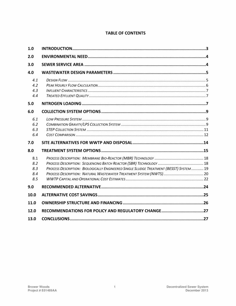
TABLE OF CONTENTS
INTRODUCTION ...............................................................................................................3 1.0
ENVIRONMENTAL NEED ..................................................................................................4 2.0
SEWER SERVICE AREA .....................................................................................................4 3.0
WASTEWATER DESIGN PARAMETERS .............................................................................5 4.0
4.1 DESIGN FLOW ............................................................................................................................ 5
4.2 PEAK HOURLY FLOW CALCULATION ................................................................................................. 6
4.3 INFLUENT CHARACTERISTICS .......................................................................................................... 7
4.4 TREATED EFFLUENT QUALITY ......................................................................................................... 7
NITROGEN LOADING .......................................................................................................7 5.0
COLLECTION SYSTEM OPTIONS .......................................................................................9 6.0
6.1 LOW PRESSURE SYSTEM ............................................................................................................... 9
6.2 COMBINATION GRAVITY/LPS COLLECTION SYSTEM ............................................................................ 9
6.3 STEP COLLECTION SYSTEM ......................................................................................................... 11
6.4 COST COMPARISON ................................................................................................................... 12
SITE ALTERNATIVES FOR WWTP AND DISPOSAL ...........................................................14 7.0
TREATMENT SYSTEM OPTIONS .....................................................................................15 8.0
8.1 PROCESS DESCRIPTION: MEMBRANE BIO-REACTOR (MBR) TECHNOLOGY ............................................ 18
8.2 PROCESS DESCRIPTION: SEQUENCING BATCH REACTOR (SBR) TECHNOLOGY ......................................... 18
8.3 PROCESS DESCRIPTION: BIOLOGICALLY ENGINEERED SINGLE SLUDGE TREATMENT (BESST) SYSTEM ........... 19
8.4 PROCESS DESCRIPTION: NATURAL WASTEWATER TREATMENT SYSTEM (NWTS) .................................... 20
8.5 WWTP CAPITAL AND OPERATIONAL COST ESTIMATES ...................................................................... 22
RECOMMENDED ALTERNATIVE .....................................................................................24 9.0
ALTERNATIVE COST SAVINGS ........................................................................................25 10.0
OWNERSHIP STRUCTURE AND FINANCING ...................................................................26 11.0
RECOMMENDATIONS FOR POLICY AND REGULATORY CHANGE ...................................27 12.0
CONCLUSIONS ...............................................................................................................27 13.0
Brower Woods 2 Decentralized Sewer System Project # E01489AA December 2013
INDEX OF TABLES
TABLE 1: DESIGN INFLUENT CHARACTERISTICS ......................................................................................7
TABLE 2: DESIGN EFFLUENT CHARACTERISTICS ......................................................................................7
TABLE 3: EXISTING SYSTEM NITROGEN LOADING ...................................................................................8
TABLE 4: PROPOSED SYSTEM NITROGEN LOADING ................................................................................8
TABLE 5: CAPITAL COST ESTIMATE – COLLECTION SYSTEMS ...................................................................12
TABLE 6: ANNUAL OPERATIONAL COST ESTIMATE – COLLECTION SYSTEMS ...............................................14
TABLE 7: WWTP CAPITAL COST ESTIMATE .......................................................................................22
TABLE 8: WWTP ANNUAL OPERATIONAL COST ESTIMATE ...................................................................23
TABLE 9: CAPITAL COST FOR THE RECOMMENDED ALTERNATIVE .............................................................24
TABLE 10: ANNUAL OPERATING COST FOR THE RECOMMENDED ALTERNATIVE ..........................................24
INDEX OF PHOTOGRAPHS
PHOTOGRAPH 1: EXAMPLE BUILDING FOR MBR, SBR OR BESST SYSTEMS ..............................................17
PHOTOGRAPH 2: EXAMPLE OF A NATURAL WETLANDS TREATMENT SYSTEM .............................................17
INDEX OF APPENDICES
APPENDIX A: DRAWINGS AND FIGURES
FIGURE 1. SEWER SERVICE AREA
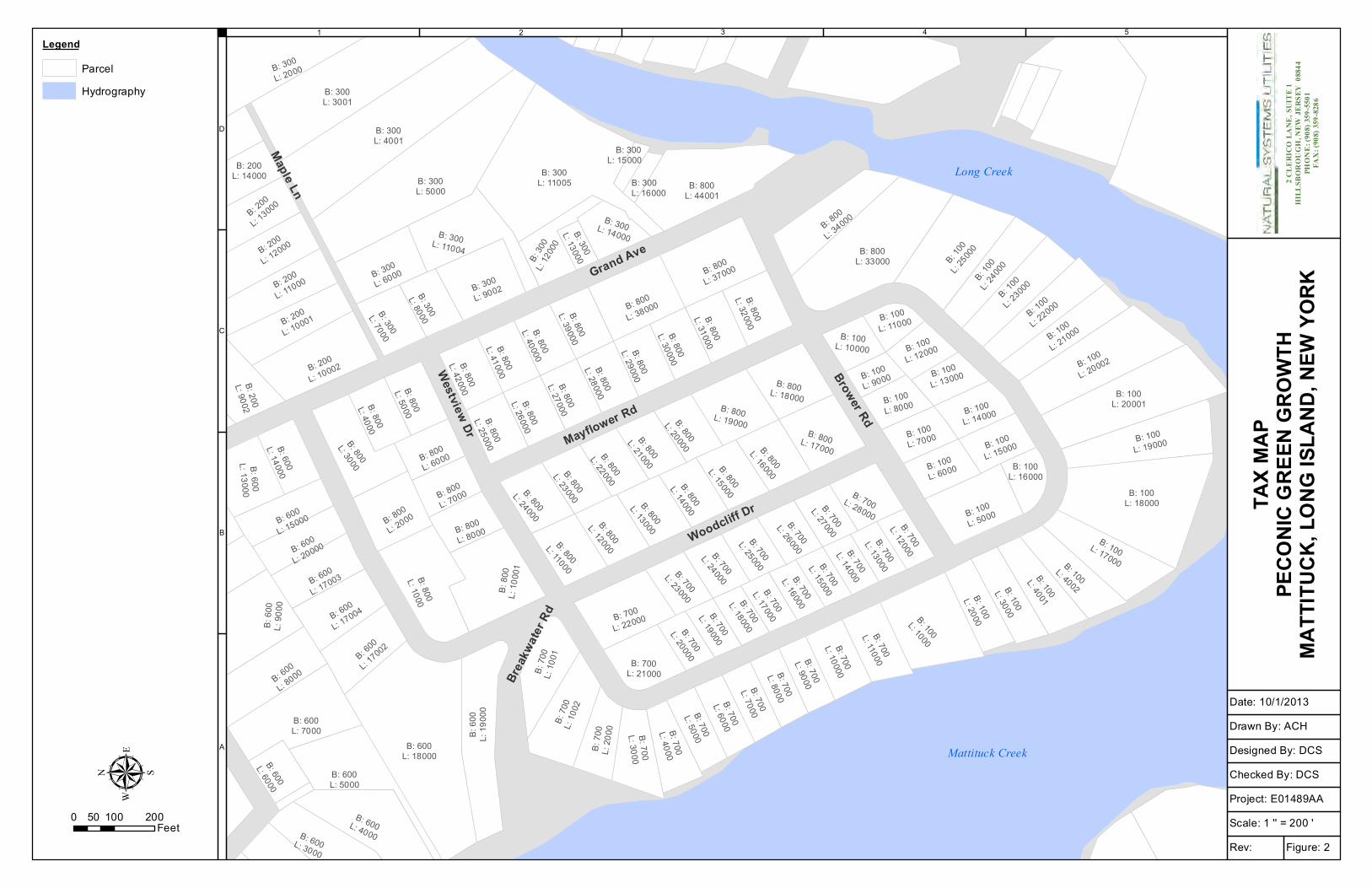
FIGURE 2. TAX MAP
FIGURE 3. ELEVATION
FIGURE 4. COMBINED GRAVITY/LPS COLLECTION SYSTEM – AERIAL
FIGURE 5. COMBINED GRAVITY/LPS COLLECTION SYSTEM – ELEVATION
FIGURE 6. WWTP SITE LOCATION
TOWN OF SOUTHOLD MAPPING
• Parcel Acreage
• Influence Zones
• Soils – Drainage Class
• Ground Water Depth
• Impaired Water
APPENDIX B: WWTP LAYOUTS
NTWS AND ADVANTEX PROCESS FLOW DIAGRAMS
APPENDIX C: LOW PRESSURE SEWER DESIGN REPORT
Brower Woods 3 Decentralized Sewer System Project # E01489AA December 2013
This report was executed on behalf of:
Peconic Green Growth, Inc
651 West Main Street
Riverhead, NY 11901
Funded by a grant from:
The Long Island Sound Study and the National Fish and Wildlife Foundation
INTRODUCTION 1.0
On behalf of Peconic Green Growth, Inc., Natural Systems Utilities (NSU) has prepared this technical
feasibility report which identifies and compares options for deployment of a decentralized wastewater
utility solution as a means of mitigating nitrogen loadings that are affecting the quality of the Long Island
Sound Watershed. This report was prepared in accordance with a grant funded by the Long Island
Sound Study and the National Fish and Wildlife Foundation (Grant Project ID# 1401.12.033406).
This report provides an evaluation of a decentralized system that would serve the existing residential
community referred to herein as “Brower Woods”. Brower Woods is located on the eastern banks of
Mattituck Creek in the Town of Southhold, Suffolk County, NY. A map defining the project boundary is
provided in Figure 1 of Appendix A. This community was selected by Peconic Green Growth, Inc. (PGG)
after careful analysis of existing comminutes located within the Towns of Riverhead and Southold.
Brower Woods was determined to be suitable for a decentralized sewer system as it meets the following
criteria:
• Environmental need is defined. Nitrogen present in marine environments serves as a food
source for algal blooms. When these algal blooms thrive, they can severely reduce oxygen
which is essential to the survival of most marine life. In addition, in certain cases, algal blooms
can lead to the formation of toxins (i.e. saxitoxin) that can be harmful to humans. As in the case
of Mattituck Creek, there has been recent shellfish bed closures due to toxic algal blooms
caused by Alexandrium. Alexandrium synthesizes saxitoxin that leads to the human illness
known as paralytic shellfish poisoning. In 2009, Mattituck Creek had higher densities of
Alexandrium than any other system monitored on Long Island (Gobler 2011; Final report to the
Long Island Sound Study). In August of 2013, Stony Brook University surveyed oxygen levels in
bottom waters of tributaries across Nassau and Suffolk County. Mattituck Creek had the lowest
oxygen levels at 0.04 mg per liter, a level that is practically anoxic (severely oxygen deficient).
• Existing disposal systems are comprised of either cesspools or septic systems. In the case of
Brower Woods, all existing properties are served by cesspools or septics, which is contributing to
excessive nitrogen levels found in the Mattituck Creek.
• Groundwater beneath the project is located within a 2 year time of travel to adjacent surface
water bodies. According to the Influence Map prepared by the Town of Southold (Appendix A),
Brower Woods 4 Decentralized Sewer System Project # E01489AA December 2013
approximately 90% of the homes located within the proposed Brower Woods sewer service area
are located within the 2 year zone of influence.
• Project septic density exceeds that of current conventional treatment standards.
• There is no feasible alternative for connection to a centralized sewer facility. The nearest town
sewer system is in Riverhead, which is located approximately 9 miles from Brower Woods.
• Projected wastewater flows shall be greater than or equal to 30,000 gpd. The 30,000 gpd
threshold was selected as a requirement for this study as it is the limit of alternative
intermediate systems approved by Suffolk County.
Preliminary designs were prepared to define the components of the Brower Woods Sewer System
(BWSS). Preliminary designs include the collection system, treatment system and disposal system. Each
design was prepared in accordance with New York State Department of Environmental Conservation
(NYSDEC) and Suffolk County Department of Health Services (SCDHS) Standards. Alternatives were
developed for the collection system and treatment system in order to identify a cost effective approach
for the system. Both capital and operational expenses were determined for each alternative. The cost
estimates presented in this report are high level estimates (25% +/-) and shall not be misconstrued as
firm pricing.
This report assesses options for ownership and financing based on the concept sewer system and costs.
These options are presented in Section 11.0.
ENVIRONMENTAL NEED 2.0
The primary purpose of a decentralized wastewater collection and treatment system is to eliminate
existing, inadequate septic systems and cesspools and reduce the quantity of nitrogen and other
nutrients entering the groundwater and surrounding water bodies. Reducing these nutrient loads will
improve the water quality for aquatic and terrestrial wildlife species and for human use and recreation.
A more detailed analysis of the need for the types of systems proposed in this report can be found in the
Water Quality section of the report titled “Plan for Decentralized Wastewater Treatment, North Fork in
the Long Island Sound Watershed” prepared by Peconic Green Growth, Inc., a not-for-profit
organization, to be published in March 2014.
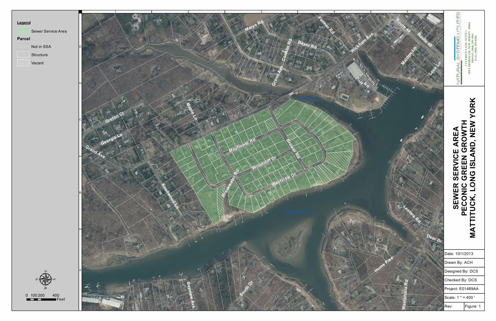
SEWER SERVICE AREA 3.0
The properties included within the proposed Brower Woods Sewer Service Area (SSA) are depicted on
the Sewer Service Area Map (Appendix A). The SSA is located on the east side of Mattituck Creek
approximately 0.4 miles north of Middle Road in the hamlet of Mattituck, Town of Southold, Suffolk
County, NY. The sewer service area consists of approximately 98 occupied lots and 6 vacant lots (104
Brower Woods 5 Decentralized Sewer System Project # E01489AA December 2013
lots in total). The proposed SSA totals 49.03 acres, exclusive of right-of-ways. The average parcel area is
0.47 acres. The SSA is located within zone R-40 Residential Low Density (1 acre). All existing
construction located within the SSA consists of single-family homes.
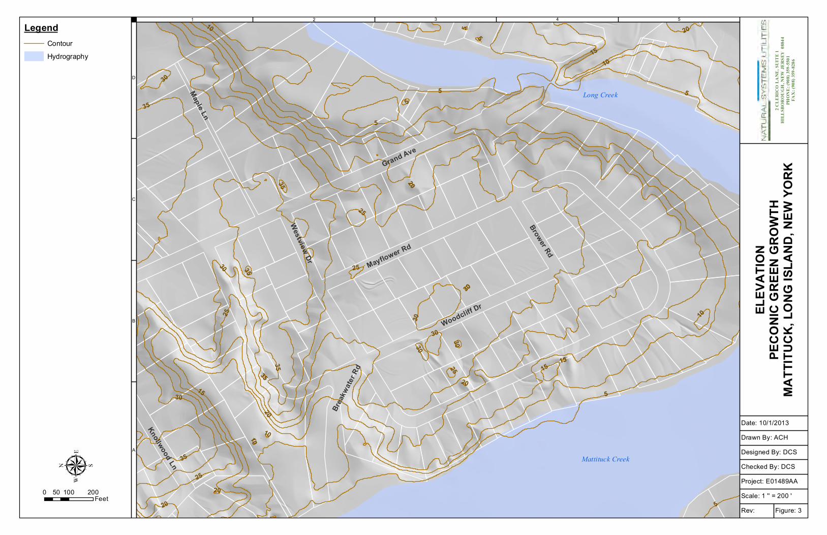
Existing topography is shown on the Elevation Map (Appendix A). The SSA ranges in elevation between
5 feet - 35 feet msl. The depth to groundwater within the SSA limits is greater than 13.1 ft in most
locations. However, there are areas, primarily along the southern tip of Brower Woods, where the
depth to groundwater is less than 1 ft.
The roadways within the community consist of gently sloped, asphalt-paved roads without curbing. A
majority of the homes’ finished floor elevations are constructed at or near the adjacent road grade. Gas
and water utilities are present throughout the community. Storm sewers were located within a small
portion of the community.
Brower Woods is located within Groundwater Management Zone IV. Wastewater generated by the
homes within the community currently discharges to individual cesspools or septic systems, depending
on when the home was built. For purposes of this report, it is assumed that 75% of existing homes
discharge to cesspools. According to the Influence Map prepared by the Town of Southold (Appendix A)
approximately 90% of existing homes located within the proposed Brower Woods sewer service area are
located within the 2 year zone of influence of Mattituck Creek. The project density, lack of treatment
and its close proximity to surface waters suggest that the nitrogen loading from this community is more
prevalent than other residential areas along the eastern shoreline of Mattituck Creek.
There are no existing sewer districts located within close proximity of Brower Woods. The closest sewer
area is a 0.04 MGD private sewer area located more than 5 miles away in the Town Riverhead. The
nearest town sewer district is the Riverhead Sewer District (TSD-05) located approximately 9 miles from
the project site. The lack of sewer systems within the vicinity of the project supports the concept of a
decentralized system to mitigate nitrogen.
WASTEWATER DESIGN PARAMETERS 4.0
The wastewater design parameters used in this analysis are detailed in the following sections of this
report.
4.1 Design Flow
The SSA consists of 104 lots in total. 98 of the existing lots are built out and consist of single
family homes. The remaining 6 lots are vacant. Wastewater flow estimates were calculated
using the hydraulic load unit flow criteria provided in the “Standards for Approval of Plans and
Brower Woods 6 Decentralized Sewer System Project # E01489AA December 2013
Construction for Sewage Disposal Systems for Other Than Single-Family Residences” issued by
the Suffolk County Department of Health Services (SCDHS).
Existing Use = 98 single family homes x 300 gpd/home = 29,400 gpd
Maximum Build Out = 104 single family homes x 300 gpd/home = 31,200 gpd
Estimated Design Flow = 30,000 gpd
For purposes of this report, it is assumed that 100 homes will be served by the decentralized
sewer system. This would result in a design flow of 30,000 gpd. The WWTP may be able to
accept additional connections in the future if it is proven that the WWTP has sufficient capacity
to serve the additional flow. Theoretical flow values are typically greater than actual flows in
order to account for the impact of inflow and infiltration of stormwater or groundwater that can
increase hydraulic load on sewers and to account for variations in wastewater generation rates
that occur during peak events. As discussed later in this report, a low pressure sewer system
would greatly minimize inflow and infiltration which suggests that the facility may have future
capacity to service more than 100 connections.
4.2 Peak Hourly Flow Calculation
The total population served by the wastewater treatment system is estimated at 400 persons
based on the following:
30,000 gpd / 75 gpd per capita = 400 persons
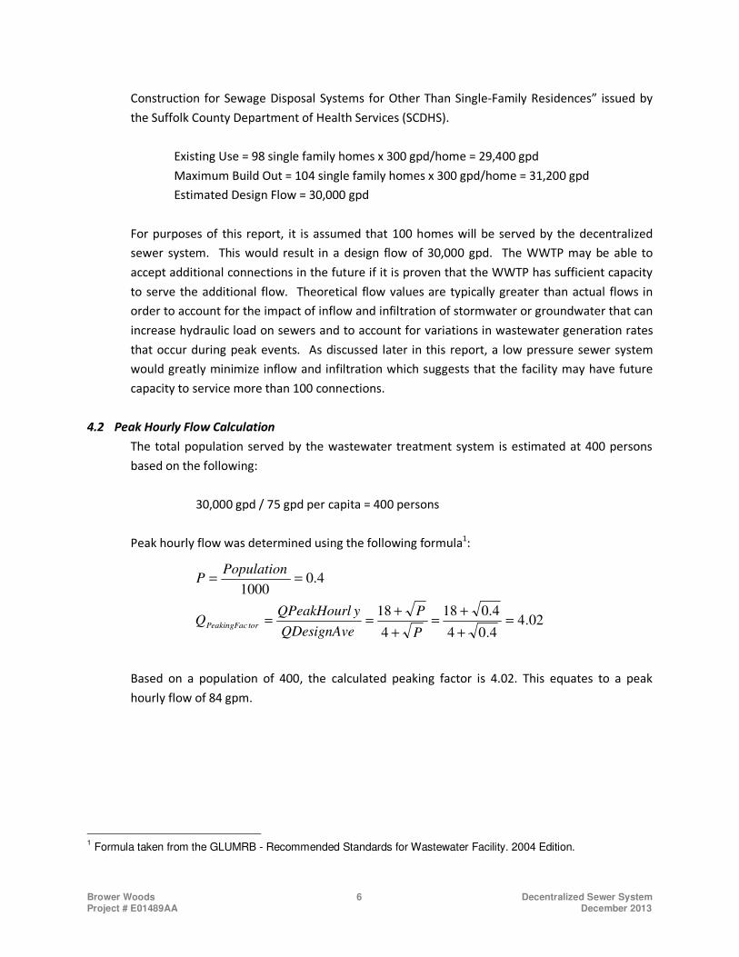
Peak hourly flow was determined using the following formula1:
Based on a population of 400, the calculated peaking factor is 4.02. This equates to a peak
hourly flow of 84 gpm.
1 Formula taken from the GLUMRB - Recommended Standards for Wastewater Facility. 2004 Edition.
02.44.04
4.018
4
18
4.01000
=
+
+=
+
+==
==
P
P
QDesignAve
yQPeakHourlQ
PopulationP
torPeakingFac
Brower Woods 7 Decentralized Sewer System Project # E01489AA December 2013
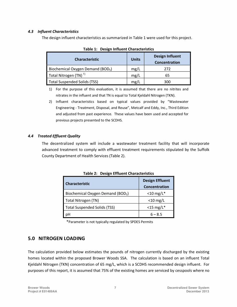
4.3 Influent Characteristics
The design influent characteristics as summarized in Table 1 were used for this project.
Table 1: Design Influent Characteristics
Characteristic Units Design Influent
Concentration
Biochemical Oxygen Demand (BOD5) mg/L 272
Total Nitrogen (TN) 1) mg/L 65
Total Suspended Solids (TSS) mg/L 300
1) For the purpose of this evaluation, it is assumed that there are no nitrites and
nitrates in the influent and that TN is equal to Total Kjeldahl Nitrogen (TKN).
2) Influent characteristics based on typical values provided by “Wastewater
Engineering - Treatment, Disposal, and Reuse”, Metcalf and Eddy, Inc., Third Edition
and adjusted from past experience. These values have been used and accepted for
previous projects presented to the SCDHS.
4.4 Treated Effluent Quality
The decentralized system will include a wastewater treatment facility that will incorporate
advanced treatment to comply with effluent treatment requirements stipulated by the Suffolk
County Department of Health Services (Table 2).
Table 2: Design Effluent Characteristics
Characteristic Design Effluent
Concentration
Biochemical Oxygen Demand (BOD5) <10 mg/L*
Total Nitrogen (TN) <10 mg/L
Total Suspended Solids (TSS) <15 mg/L*
pH 6 – 8.5
*Parameter is not typically regulated by SPDES Permits
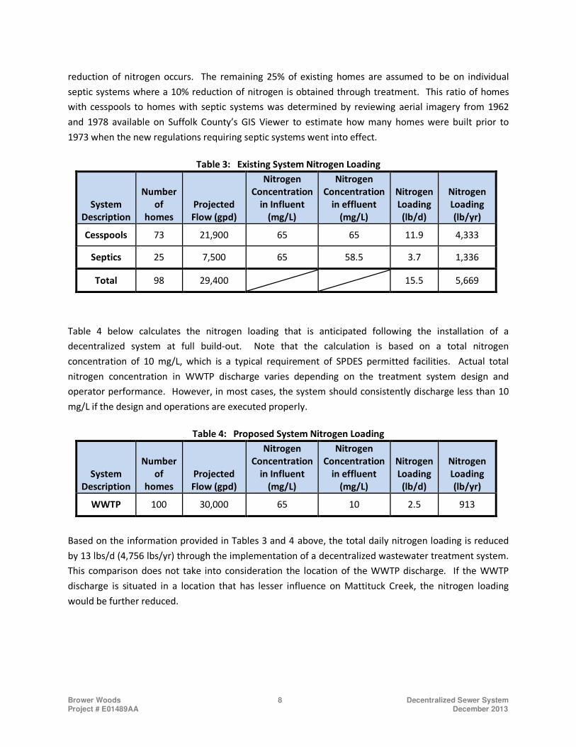
NITROGEN LOADING 5.0
The calculation provided below estimates the pounds of nitrogen currently discharged by the existing
homes located within the proposed Brower Woods SSA. The calculation is based on an influent Total
Kjeldahl Nitrogen (TKN) concentration of 65 mg/L, which is a SCDHS recommended design influent. For
purposes of this report, it is assumed that 75% of the existing homes are serviced by cesspools where no
Brower Woods 8 Decentralized Sewer System Project # E01489AA December 2013
reduction of nitrogen occurs. The remaining 25% of existing homes are assumed to be on individual
septic systems where a 10% reduction of nitrogen is obtained through treatment. This ratio of homes
with cesspools to homes with septic systems was determined by reviewing aerial imagery from 1962
and 1978 available on Suffolk County’s GIS Viewer to estimate how many homes were built prior to
1973 when the new regulations requiring septic systems went into effect.
Table 3: Existing System Nitrogen Loading
System
Description
Number
of
homes
Projected
Flow (gpd)
Nitrogen
Concentration
in Influent
(mg/L)
Nitrogen
Concentration
in effluent
(mg/L)
Nitrogen
Loading
(lb/d)
Nitrogen
Loading
(lb/yr)
Cesspools 73 21,900 65 65 11.9 4,333
Septics 25 7,500 65 58.5 3.7 1,336
Total 98 29,400
15.5 5,669
Table 4 below calculates the nitrogen loading that is anticipated following the installation of a
decentralized system at full build-out. Note that the calculation is based on a total nitrogen
concentration of 10 mg/L, which is a typical requirement of SPDES permitted facilities. Actual total
nitrogen concentration in WWTP discharge varies depending on the treatment system design and
operator performance. However, in most cases, the system should consistently discharge less than 10
mg/L if the design and operations are executed properly.
Table 4: Proposed System Nitrogen Loading
System
Description
Number
of
homes
Projected
Flow (gpd)
Nitrogen
Concentration
in Influent
(mg/L)
Nitrogen
Concentration
in effluent
(mg/L)
Nitrogen
Loading
(lb/d)
Nitrogen
Loading
(lb/yr)
WWTP 100 30,000 65 10 2.5 913
Based on the information provided in Tables 3 and 4 above, the total daily nitrogen loading is reduced
by 13 lbs/d (4,756 lbs/yr) through the implementation of a decentralized wastewater treatment system.
This comparison does not take into consideration the location of the WWTP discharge. If the WWTP
discharge is situated in a location that has lesser influence on Mattituck Creek, the nitrogen loading
would be further reduced.
Brower Woods 9 Decentralized Sewer System Project # E01489AA December 2013
COLLECTION SYSTEM OPTIONS 6.0
This report evaluates two options for the proposed wastewater collection system; a low pressure sewer
system and a combination gravity/LPS collection system. These are described in detail in Section 6.1 and
6.2 of this report.
6.1 Low Pressure System
In a low pressure sewer (LPS) system the wastewater is conveyed from each home to an on-site,
individual pump station through a PVC lateral. The pump station collects the wastewater and
discharges it through a low pressure piping network which ultimately discharges flow to the
proposed WWTP. The LPS network consists of small diameter PVC pipes that will run down each
street within the SSA. A layout of the system can be found in the report titled “Brower Woods -
Low Pressure Sewer Design” by Water Resources Technologies in Appendix C.
Each individual pump station consists of a buried simplex grinder pump system, check valve,
high density polyethylene tank and controls. The benefits of this type of system include lower
cost, easier installation, and a significant reduction in the potential for extraneous stormwater
or groundwater to enter the system. Duplex systems are available which provides for
redundancy in case a pump were to malfunction. The cost differential between a simplex and
duplex pump system is valued at approximately $ 5,000 per station. If simplex systems are
selected, SCDHS requires each homeowner enter into a lifetime maintenance contract with the
pump station manufacturer or other qualified service company.
For this SSA, the following approximate quantities for the pressure system were calculated
based on 100 residences:
• 9,500 Linear Feet (LF) of 1 ¼” HDPE pipe for house services
• 2,000 LF of 4” PVC from house to pump stations
• 11,200 LF of 2” to 4” HDPE pipe for collection system
• 100 Simplex pump stations with controls
• 11 Flushing connections
6.2 Combination Gravity/LPS Collection System
The option of installing a gravity system in the SSA was also evaluated. Due to the variable
topography within the SSA, a collection system operating completely by gravity was cost
prohibitive due to the excessive sewer main depth that would be required. Therefore, a
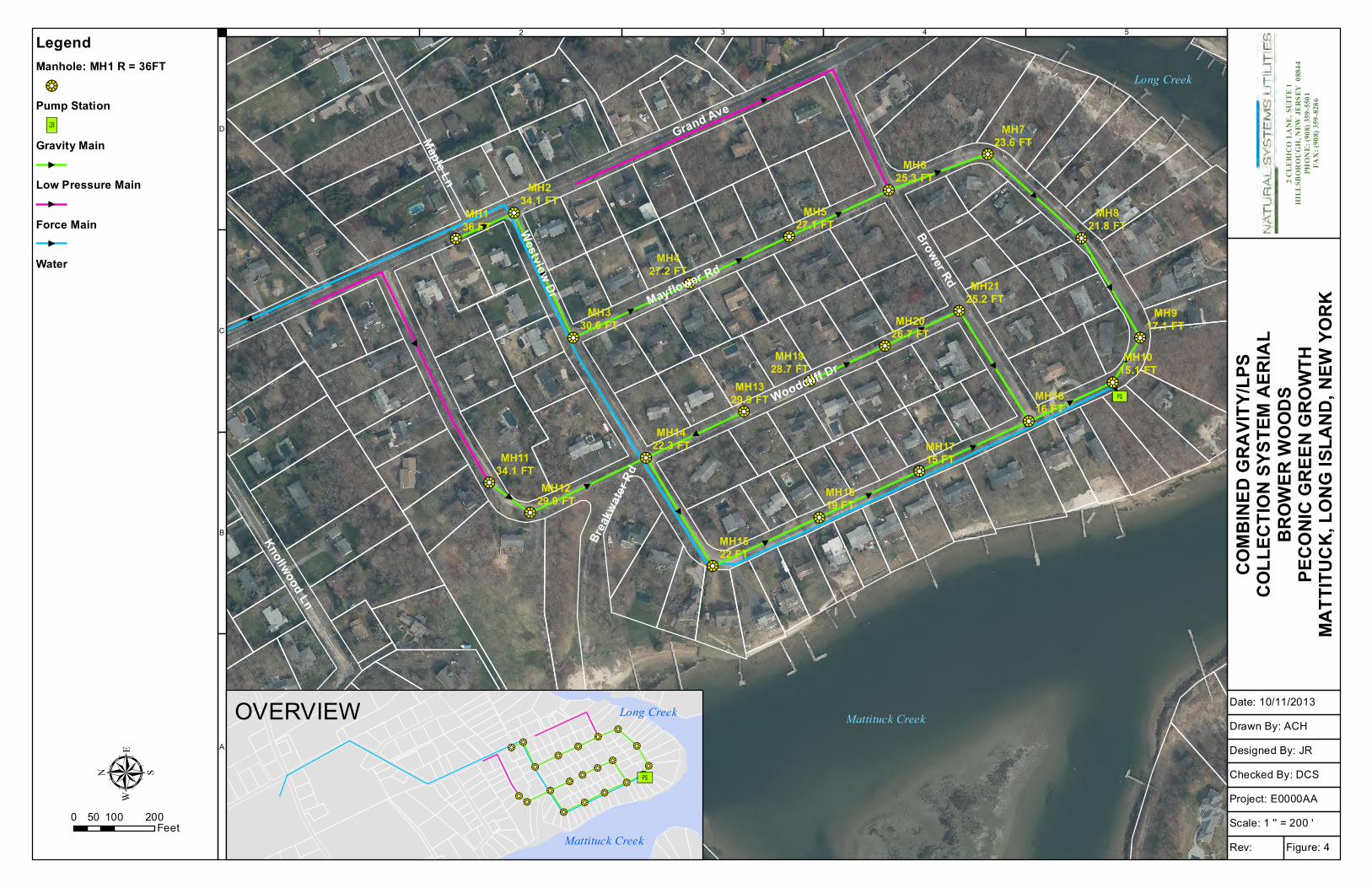
combination of a gravity and a low pressure system was considered. A conceptual layout of the
gravity/LPS system is provided in Figure 4 (Appendix A)
Brower Woods 10 Decentralized Sewer System Project # E01489AA December 2013
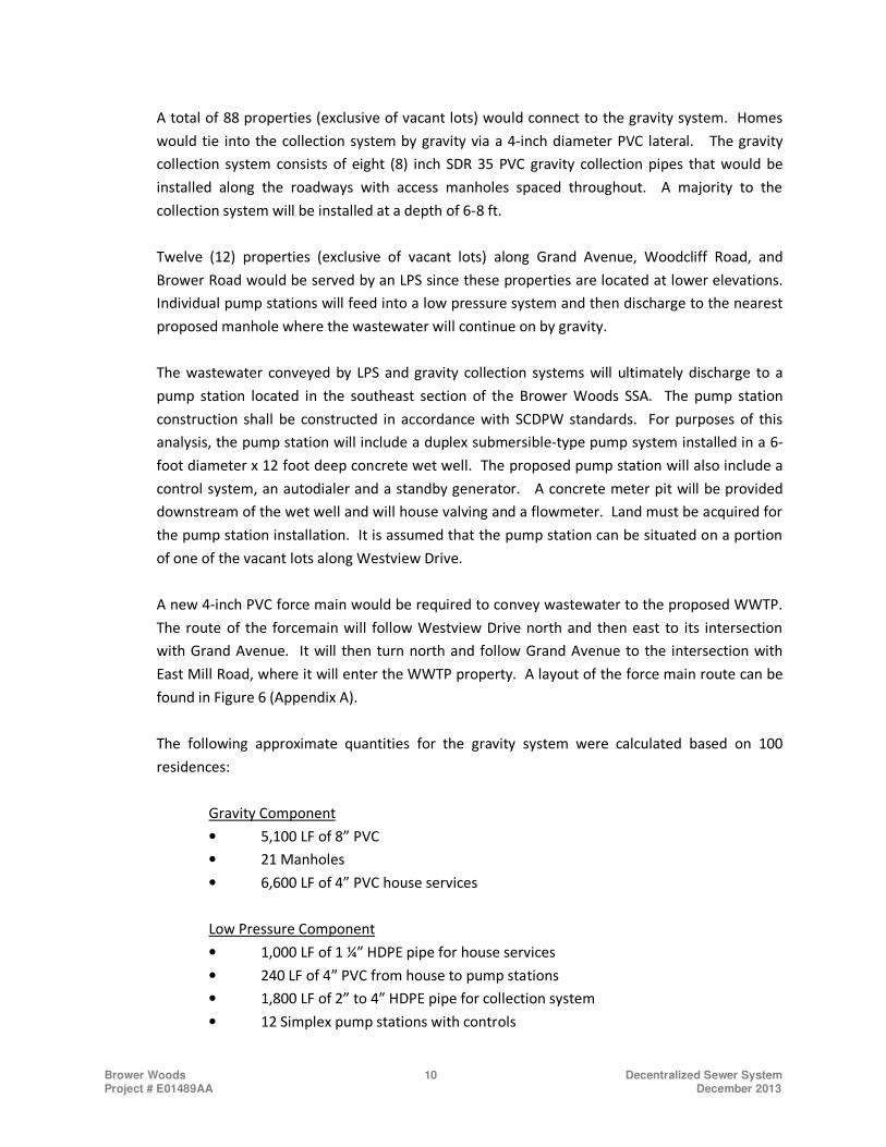
A total of 88 properties (exclusive of vacant lots) would connect to the gravity system. Homes
would tie into the collection system by gravity via a 4-inch diameter PVC lateral. The gravity
collection system consists of eight (8) inch SDR 35 PVC gravity collection pipes that would be
installed along the roadways with access manholes spaced throughout. A majority to the
collection system will be installed at a depth of 6-8 ft.
Twelve (12) properties (exclusive of vacant lots) along Grand Avenue, Woodcliff Road, and
Brower Road would be served by an LPS since these properties are located at lower elevations.
Individual pump stations will feed into a low pressure system and then discharge to the nearest
proposed manhole where the wastewater will continue on by gravity.
The wastewater conveyed by LPS and gravity collection systems will ultimately discharge to a
pump station located in the southeast section of the Brower Woods SSA. The pump station
construction shall be constructed in accordance with SCDPW standards. For purposes of this
analysis, the pump station will include a duplex submersible-type pump system installed in a 6-
foot diameter x 12 foot deep concrete wet well. The proposed pump station will also include a
control system, an autodialer and a standby generator. A concrete meter pit will be provided
downstream of the wet well and will house valving and a flowmeter. Land must be acquired for
the pump station installation. It is assumed that the pump station can be situated on a portion
of one of the vacant lots along Westview Drive.
A new 4-inch PVC force main would be required to convey wastewater to the proposed WWTP.
The route of the forcemain will follow Westview Drive north and then east to its intersection
with Grand Avenue. It will then turn north and follow Grand Avenue to the intersection with
East Mill Road, where it will enter the WWTP property. A layout of the force main route can be
found in Figure 6 (Appendix A).
The following approximate quantities for the gravity system were calculated based on 100
residences:
Gravity Component
• 5,100 LF of 8” PVC
• 21 Manholes
• 6,600 LF of 4” PVC house services
Low Pressure Component
• 1,000 LF of 1 ¼” HDPE pipe for house services
• 240 LF of 4” PVC from house to pump stations
• 1,800 LF of 2” to 4” HDPE pipe for collection system
• 12 Simplex pump stations with controls
Brower Woods 11 Decentralized Sewer System Project # E01489AA December 2013
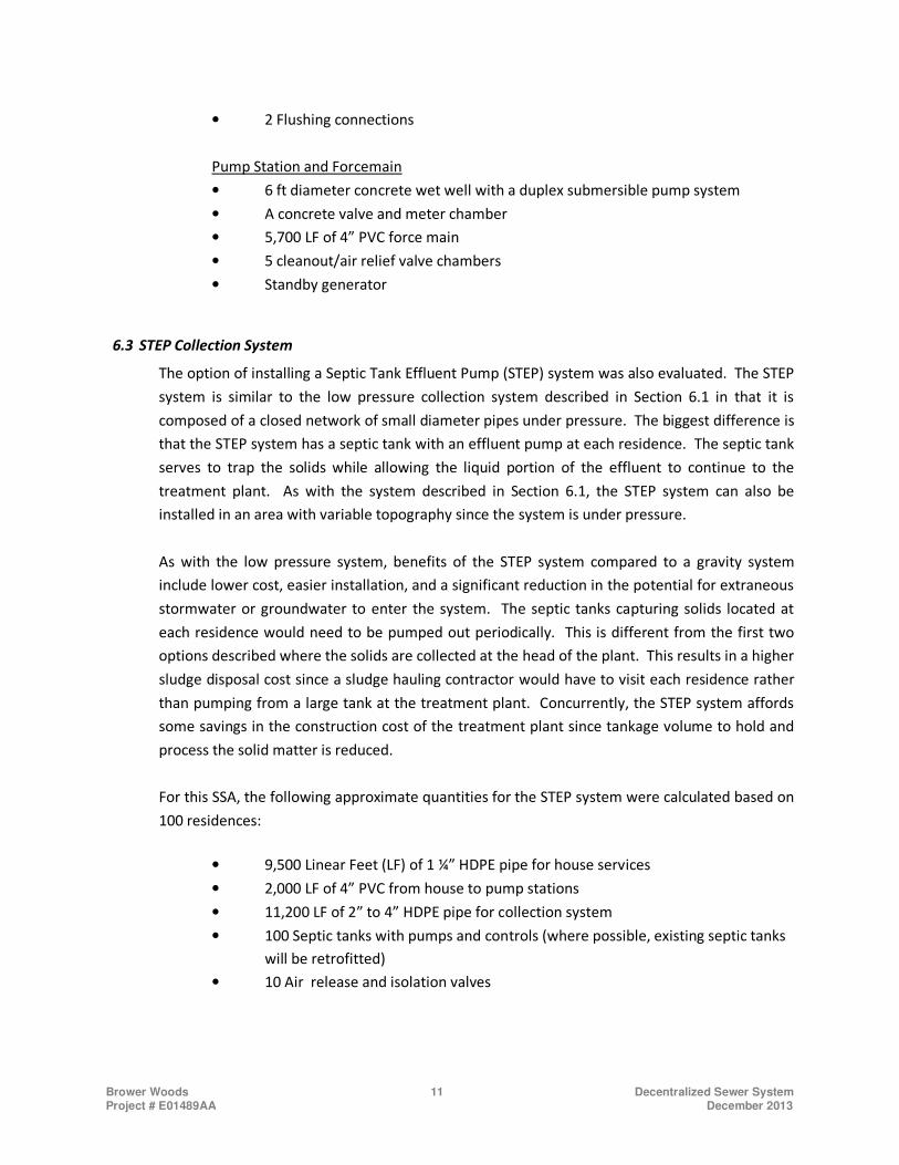
• 2 Flushing connections
Pump Station and Forcemain
• 6 ft diameter concrete wet well with a duplex submersible pump system
• A concrete valve and meter chamber
• 5,700 LF of 4” PVC force main
• 5 cleanout/air relief valve chambers
• Standby generator
6.3 STEP Collection System
The option of installing a Septic Tank Effluent Pump (STEP) system was also evaluated. The STEP
system is similar to the low pressure collection system described in Section 6.1 in that it is
composed of a closed network of small diameter pipes under pressure. The biggest difference is
that the STEP system has a septic tank with an effluent pump at each residence. The septic tank
serves to trap the solids while allowing the liquid portion of the effluent to continue to the
treatment plant. As with the system described in Section 6.1, the STEP system can also be
installed in an area with variable topography since the system is under pressure.
As with the low pressure system, benefits of the STEP system compared to a gravity system
include lower cost, easier installation, and a significant reduction in the potential for extraneous
stormwater or groundwater to enter the system. The septic tanks capturing solids located at
each residence would need to be pumped out periodically. This is different from the first two
options described where the solids are collected at the head of the plant. This results in a higher
sludge disposal cost since a sludge hauling contractor would have to visit each residence rather
than pumping from a large tank at the treatment plant. Concurrently, the STEP system affords
some savings in the construction cost of the treatment plant since tankage volume to hold and
process the solid matter is reduced.
For this SSA, the following approximate quantities for the STEP system were calculated based on
100 residences:
• 9,500 Linear Feet (LF) of 1 ¼” HDPE pipe for house services
• 2,000 LF of 4” PVC from house to pump stations
• 11,200 LF of 2” to 4” HDPE pipe for collection system
• 100 Septic tanks with pumps and controls (where possible, existing septic tanks
will be retrofitted)
• 10 Air release and isolation valves
Brower Woods 12 Decentralized Sewer System Project # E01489AA December 2013
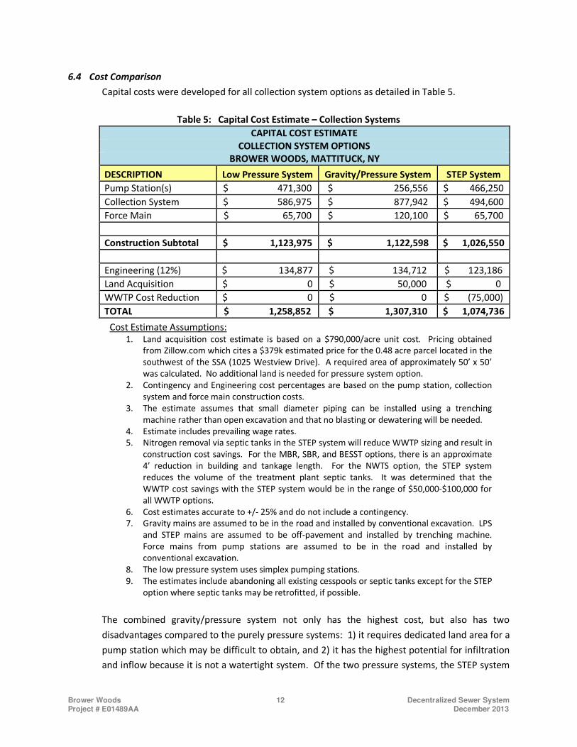
6.4 Cost Comparison
Capital costs were developed for all collection system options as detailed in Table 5.
Table 5: Capital Cost Estimate – Collection Systems
CAPITAL COST ESTIMATE
COLLECTION SYSTEM OPTIONS
BROWER WOODS, MATTITUCK, NY
DESCRIPTION Low Pressure System Gravity/Pressure System STEP System
Pump Station(s) $ 471,300 $ 256,556 $ 466,250
Collection System $ 586,975 $ 877,942 $ 494,600
Force Main $ 65,700 $ 120,100 $ 65,700
Construction Subtotal $ 1,123,975 $ 1,122,598 $ 1,026,550
Engineering (12%) $ 134,877 $ 134,712 $ 123,186
Land Acquisition $ 0 $ 50,000 $ 0
WWTP Cost Reduction $ 0 $ 0 $ (75,000)
TOTAL $ 1,258,852 $ 1,307,310 $ 1,074,736
Cost Estimate Assumptions: 1. Land acquisition cost estimate is based on a $790,000/acre unit cost. Pricing obtained
from Zillow.com which cites a $379k estimated price for the 0.48 acre parcel located in the
southwest of the SSA (1025 Westview Drive). A required area of approximately 50’ x 50’
was calculated. No additional land is needed for pressure system option.
2. Contingency and Engineering cost percentages are based on the pump station, collection
system and force main construction costs.
3. The estimate assumes that small diameter piping can be installed using a trenching
machine rather than open excavation and that no blasting or dewatering will be needed.
4. Estimate includes prevailing wage rates.
5. Nitrogen removal via septic tanks in the STEP system will reduce WWTP sizing and result in
construction cost savings. For the MBR, SBR, and BESST options, there is an approximate
4’ reduction in building and tankage length. For the NWTS option, the STEP system
reduces the volume of the treatment plant septic tanks. It was determined that the
WWTP cost savings with the STEP system would be in the range of $50,000-$100,000 for
all WWTP options.
6. Cost estimates accurate to +/- 25% and do not include a contingency.
7. Gravity mains are assumed to be in the road and installed by conventional excavation. LPS
and STEP mains are assumed to be off-pavement and installed by trenching machine.
Force mains from pump stations are assumed to be in the road and installed by
conventional excavation.
8. The low pressure system uses simplex pumping stations.
9. The estimates include abandoning all existing cesspools or septic tanks except for the STEP
option where septic tanks may be retrofitted, if possible.
The combined gravity/pressure system not only has the highest cost, but also has two
disadvantages compared to the purely pressure systems: 1) it requires dedicated land area for a
pump station which may be difficult to obtain, and 2) it has the highest potential for infiltration
and inflow because it is not a watertight system. Of the two pressure systems, the STEP system
Brower Woods 13 Decentralized Sewer System Project # E01489AA December 2013
option is the least expensive alternative to construct at a projected cost of approximately
$1,075,000. The primary cost advantage over the gravity system is the use of smaller diameter
pipe which can be installed with a trenching machine rather than by open excavation and also
the elimination of manholes in the roadway. The cost advantage over the low pressure system
is in the lower cost of the pumping systems at each residence. Another advantage of the STEP
system over the low pressure option is that the septic tanks at each residence remove rags and
debris which protects the pumps.
In addition, STEP systems provide a notable degree of wastewater treatment through septic
tanks which result in a reduction in BOD, TSS and total nitrogen. This translates to reduced
process tank volumes and building footprint. As noted in the table above, this can translate to
approximately $75,000 in construction cost savings at the wastewater treatment
plant. Treatment cost savings may be further increased depending on the technology
selected. For example, there are numerous examples of STEP systems combined with Orenco
Systems® Inc. AdvanTex® Treatment System where construction cost has proven to be highly
competitive.
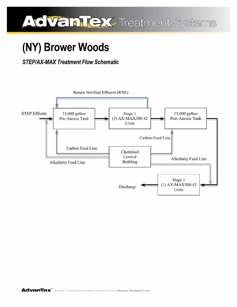
The AdvanTex Treatment System is proven technology which relies on the activated sludge
process with packed bed media filters for wastewater treatment. An example of a process flow
schematic of the STEP with AdvanTex Treatment system is provided in Appendix B. Although
this technology is approved by SCDHS in concept, there are no installations in Suffolk County.
Furthermore, this technology has not been through the SCDHS or SCDPW approval process
which make it difficult to estimate the cost of this system. Due to the limited advancement of
this technology in Suffolk County, the Advantex system not considered an alternative for
treatment in this report.
Section 10.0 of this report discusses alternatives that would further reduce the cost of the
collection system.
Brower Woods 14 Decentralized Sewer System Project # E01489AA December 2013
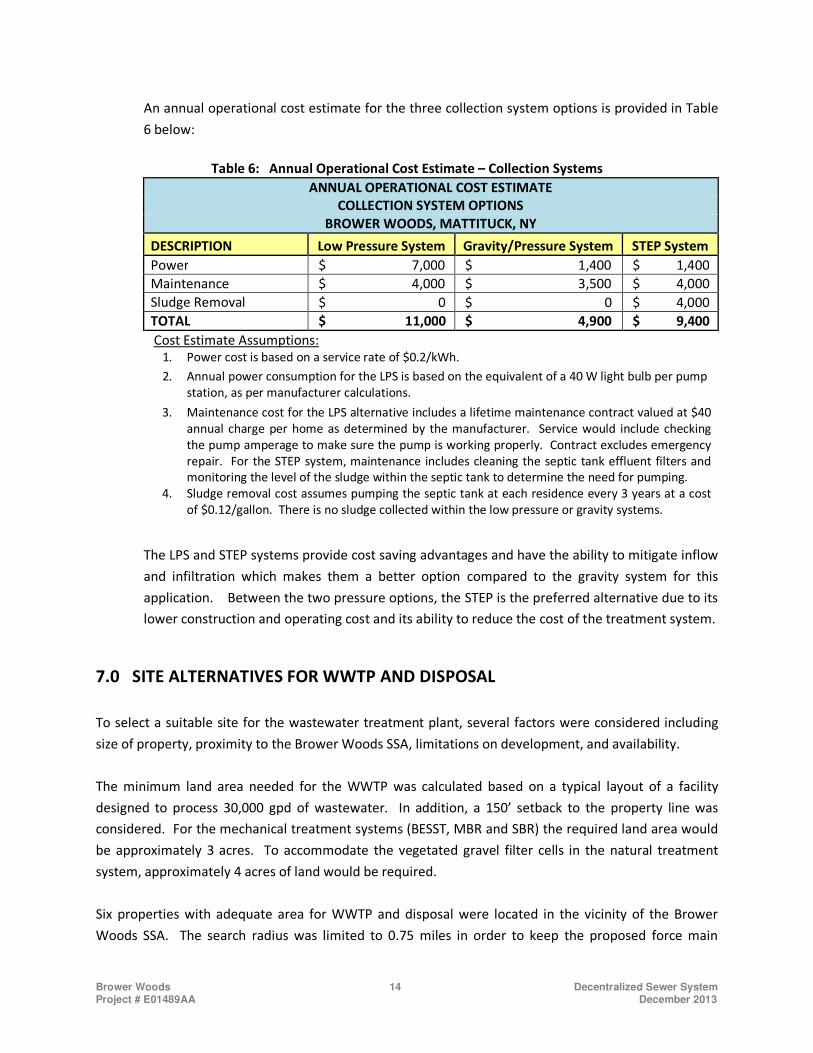
An annual operational cost estimate for the three collection system options is provided in Table
6 below:
Table 6: Annual Operational Cost Estimate – Collection Systems
ANNUAL OPERATIONAL COST ESTIMATE
COLLECTION SYSTEM OPTIONS
BROWER WOODS, MATTITUCK, NY
DESCRIPTION Low Pressure System Gravity/Pressure System STEP System
Power $ 7,000 $ 1,400 $ 1,400
Maintenance $ 4,000 $ 3,500 $ 4,000
Sludge Removal $ 0 $ 0 $ 4,000
TOTAL $ 11,000 $ 4,900 $ 9,400
Cost Estimate Assumptions: 1. Power cost is based on a service rate of $0.2/kWh.
2. Annual power consumption for the LPS is based on the equivalent of a 40 W light bulb per pump
station, as per manufacturer calculations.
3. Maintenance cost for the LPS alternative includes a lifetime maintenance contract valued at $40
annual charge per home as determined by the manufacturer. Service would include checking
the pump amperage to make sure the pump is working properly. Contract excludes emergency
repair. For the STEP system, maintenance includes cleaning the septic tank effluent filters and
monitoring the level of the sludge within the septic tank to determine the need for pumping.
4. Sludge removal cost assumes pumping the septic tank at each residence every 3 years at a cost
of $0.12/gallon. There is no sludge collected within the low pressure or gravity systems.
The LPS and STEP systems provide cost saving advantages and have the ability to mitigate inflow
and infiltration which makes them a better option compared to the gravity system for this
application. Between the two pressure options, the STEP is the preferred alternative due to its
lower construction and operating cost and its ability to reduce the cost of the treatment system.
SITE ALTERNATIVES FOR WWTP AND DISPOSAL 7.0
To select a suitable site for the wastewater treatment plant, several factors were considered including
size of property, proximity to the Brower Woods SSA, limitations on development, and availability.
The minimum land area needed for the WWTP was calculated based on a typical layout of a facility
designed to process 30,000 gpd of wastewater. In addition, a 150’ setback to the property line was
considered. For the mechanical treatment systems (BESST, MBR and SBR) the required land area would
be approximately 3 acres. To accommodate the vegetated gravel filter cells in the natural treatment
system, approximately 4 acres of land would be required.
Six properties with adequate area for WWTP and disposal were located in the vicinity of the Brower
Woods SSA. The search radius was limited to 0.75 miles in order to keep the proposed force main
Brower Woods 15 Decentralized Sewer System Project # E01489AA December 2013
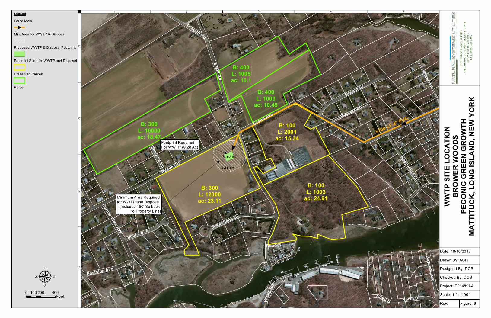
length within reason. The six parcels are shown in Figure 6 (Appendix A). Of the six parcels, four are
currently being used for agriculture. These agricultural parcels include Block 300 Lots 1200 and 16000
and Block 400, Lots 1003 and 1005. Upon further examination, it was found that three of the four
agricultural parcels are in Suffolk County’s “Purchase of Development Rights” program and therefore are
not available as WWTP development sites. Block 300, Lot 12000 was not included in this program and is
available for development. While not fully examined, there do not appear to be any environmental or
historical restrictions (i.e. wetland areas, endangered species habitat) on this property.
The other two parcels (lot Block 100, Lots 1003 and 2001) are partially developed. Undeveloped land on
these two parcels is predominantly forest or meadow. One of the parcels includes a commercial
greenhouse operation and the other with a private residence. These properties are large enough to be
subdivided so that a portion could be used for the WWTP but the willingness of the owners to sell all or
a portion of the property is unknown.
Block 300, Lot 12000 located at the northwest corner of East Mill Road and Grand Avenue, was the site
chosen for the proposed WWTP and disposal system. This property provided enough area and is
currently on the market. The site’s flat topography and use for agriculture would result in limited
clearing and earthmoving necessary during construction. It is envisioned that a portion of this property
could be split off for the treatment facility while the remainder is either developed or preserved as
farmland.
Should this property be selected, there may be opportunities to further increase the SSA to include
adjacent properties. The future WWTP could be increased in size to capture the existing Sebastian’s
Cove community to the west as well as future development on Block 300, Lot 12000. Increasing the
number of connections may help reduce the cost per user.
Another option that should be considered is reusing the treated effluent as an irrigation source for
neighboring agricultural lands. A significant number of agricultural properties are located to the east of
the WWTP site. This option would require the installation of a piping network and storage tanks. A
conceptual design and cost for such a system was beyond the scope of this report.
TREATMENT SYSTEM OPTIONS 8.0
A design concept was developed for four (4) wastewater treatment technologies, all of which are
reliable systems that are approved for use in Suffolk County. The design concepts are based on the
wastewater design parameters referenced in Section 4 of this report. The selected technologies are
listed below.
1. Membrane Bio-Reactor (MBR) Technology
Brower Woods 16 Decentralized Sewer System Project # E01489AA December 2013
2. Sequencing Batch Reactor (SBR) Technology
3. Biologically Engineered Single Sludge Treatment (BESST) System
4. Natural Wastewater Treatment System (NWTS)
Each system was designed to meet regulatory standards and the requirements of SCDHS for
redundancy. The conceptual designs assume that all process tankage must be enclosed in a building
(with the exception of the NWTS alternative). Process tankage was assumed to be of concrete
construction, because steel tankage is generally not accepted by SCDHS. The primary WWTP
infrastructure that is required for each alternative is described in Sections 8.1 to 8.4 below.
Regardless of which treatment system is chosen, the WWTP will be designed to best utilize the
designated site. Regrading will be kept to a minimum and the facility will be landscaped to blend into
the surrounding area. Fencing is typically provided around the WWTP for security but this can be
preplaced with other means such as cameras and alarms. Security is taken account in the cost estimates
in Section 8.5.
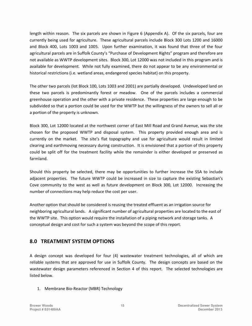
Typical facility layouts for the MBR, SBR and BESST systems can be found in Appendix B although the size
of the building and configuration of the equipment may change to best suit a particular location. Most
of the tanks and other components are either located in a building or underground. The exterior of the
building can be designed to include architectural features or paint schemes to blend it into the local
surroundings. An example of a building for the MBR, SBR and BESST systems can be found in
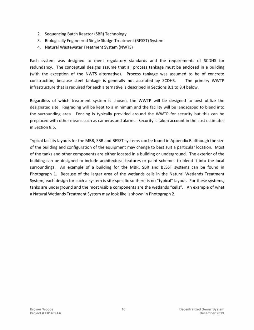
Photograph 1. Because of the larger area of the wetlands cells in the Natural Wetlands Treatment
System, each design for such a system is site specific so there is no “typical” layout. For these systems,
tanks are underground and the most visible components are the wetlands “cells”. An example of what
a Natural Wetlands Treatment System may look like is shown in Photograph 2.
Brower Woods 17 Decentralized Sewer System Project # E01489AA December 2013
Photograph 1: Example Building for MBR, SBR or BESST Systems
Photograph 2: Example of a Natural Wetlands Treatment System
Brower Woods 18 Decentralized Sewer System Project # E01489AA December 2013
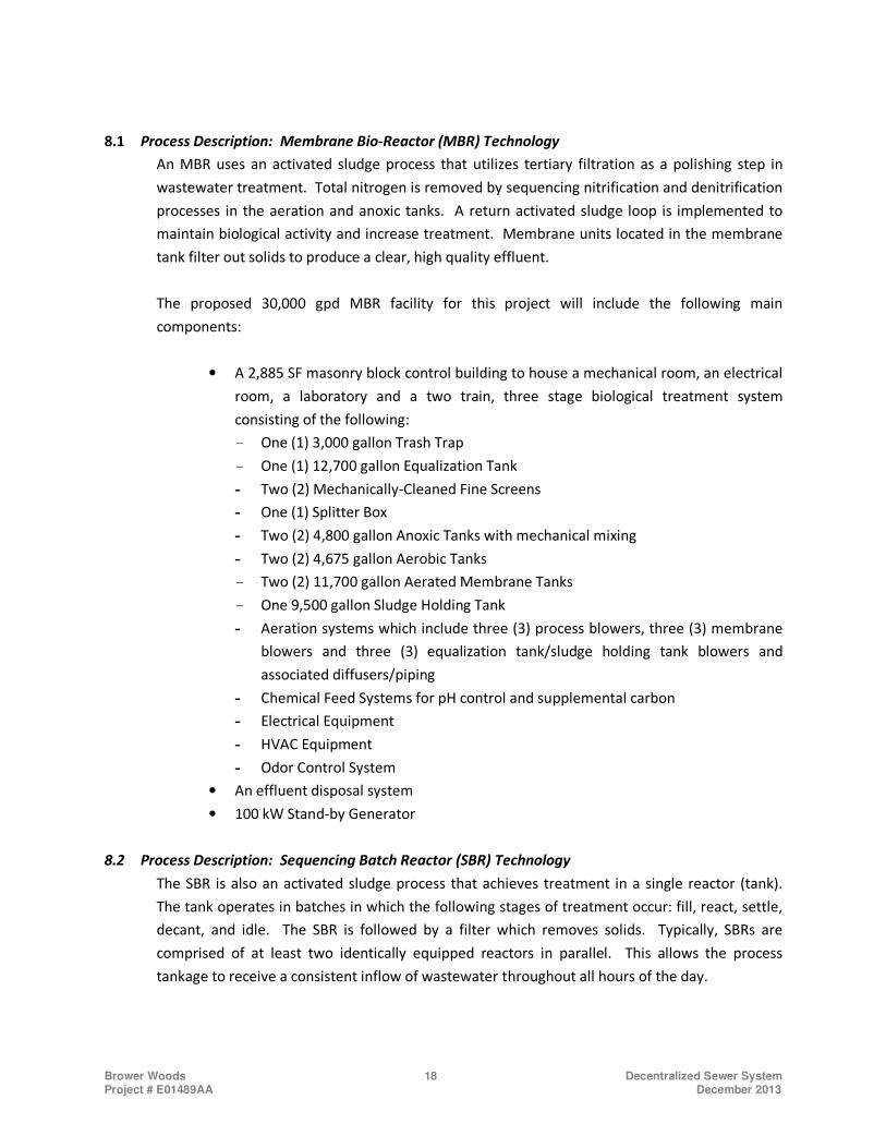
8.1 Process Description: Membrane Bio-Reactor (MBR) Technology
An MBR uses an activated sludge process that utilizes tertiary filtration as a polishing step in
wastewater treatment. Total nitrogen is removed by sequencing nitrification and denitrification
processes in the aeration and anoxic tanks. A return activated sludge loop is implemented to
maintain biological activity and increase treatment. Membrane units located in the membrane
tank filter out solids to produce a clear, high quality effluent.
The proposed 30,000 gpd MBR facility for this project will include the following main
components:
• A 2,885 SF masonry block control building to house a mechanical room, an electrical
room, a laboratory and a two train, three stage biological treatment system
consisting of the following:
- One (1) 3,000 gallon Trash Trap
- One (1) 12,700 gallon Equalization Tank
- Two (2) Mechanically-Cleaned Fine Screens
- One (1) Splitter Box
- Two (2) 4,800 gallon Anoxic Tanks with mechanical mixing
- Two (2) 4,675 gallon Aerobic Tanks
- Two (2) 11,700 gallon Aerated Membrane Tanks
- One 9,500 gallon Sludge Holding Tank
- Aeration systems which include three (3) process blowers, three (3) membrane
blowers and three (3) equalization tank/sludge holding tank blowers and
associated diffusers/piping
- Chemical Feed Systems for pH control and supplemental carbon
- Electrical Equipment
- HVAC Equipment
- Odor Control System
• An effluent disposal system
• 100 kW Stand-by Generator
8.2 Process Description: Sequencing Batch Reactor (SBR) Technology
The SBR is also an activated sludge process that achieves treatment in a single reactor (tank).
The tank operates in batches in which the following stages of treatment occur: fill, react, settle,
decant, and idle. The SBR is followed by a filter which removes solids. Typically, SBRs are
comprised of at least two identically equipped reactors in parallel. This allows the process
tankage to receive a consistent inflow of wastewater throughout all hours of the day.
Brower Woods 19 Decentralized Sewer System Project # E01489AA December 2013
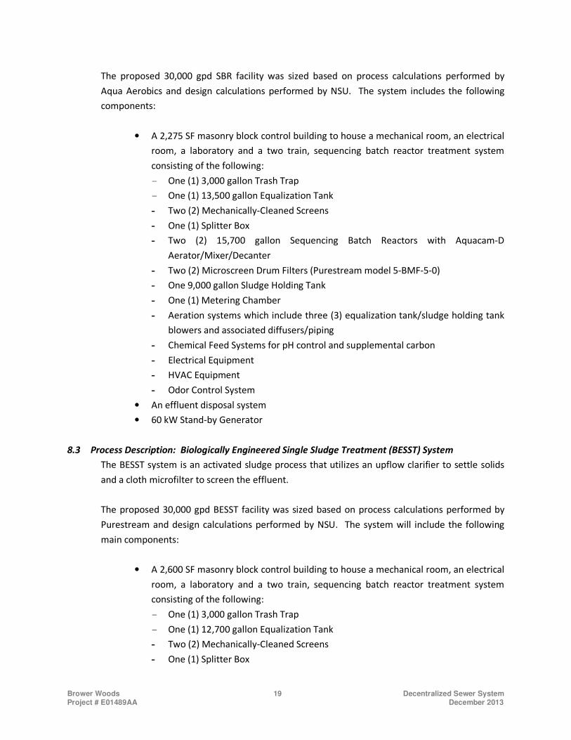
The proposed 30,000 gpd SBR facility was sized based on process calculations performed by
Aqua Aerobics and design calculations performed by NSU. The system includes the following
components:
• A 2,275 SF masonry block control building to house a mechanical room, an electrical
room, a laboratory and a two train, sequencing batch reactor treatment system
consisting of the following:
- One (1) 3,000 gallon Trash Trap
- One (1) 13,500 gallon Equalization Tank
- Two (2) Mechanically-Cleaned Screens
- One (1) Splitter Box
- Two (2) 15,700 gallon Sequencing Batch Reactors with Aquacam-D
Aerator/Mixer/Decanter
- Two (2) Microscreen Drum Filters (Purestream model 5-BMF-5-0)
- One 9,000 gallon Sludge Holding Tank
- One (1) Metering Chamber
- Aeration systems which include three (3) equalization tank/sludge holding tank
blowers and associated diffusers/piping
- Chemical Feed Systems for pH control and supplemental carbon
- Electrical Equipment
- HVAC Equipment
- Odor Control System
• An effluent disposal system
• 60 kW Stand-by Generator
8.3 Process Description: Biologically Engineered Single Sludge Treatment (BESST) System
The BESST system is an activated sludge process that utilizes an upflow clarifier to settle solids
and a cloth microfilter to screen the effluent.
The proposed 30,000 gpd BESST facility was sized based on process calculations performed by
Purestream and design calculations performed by NSU. The system will include the following
main components:
• A 2,600 SF masonry block control building to house a mechanical room, an electrical
room, a laboratory and a two train, sequencing batch reactor treatment system
consisting of the following:
- One (1) 3,000 gallon Trash Trap
- One (1) 12,700 gallon Equalization Tank
- Two (2) Mechanically-Cleaned Screens
- One (1) Splitter Box
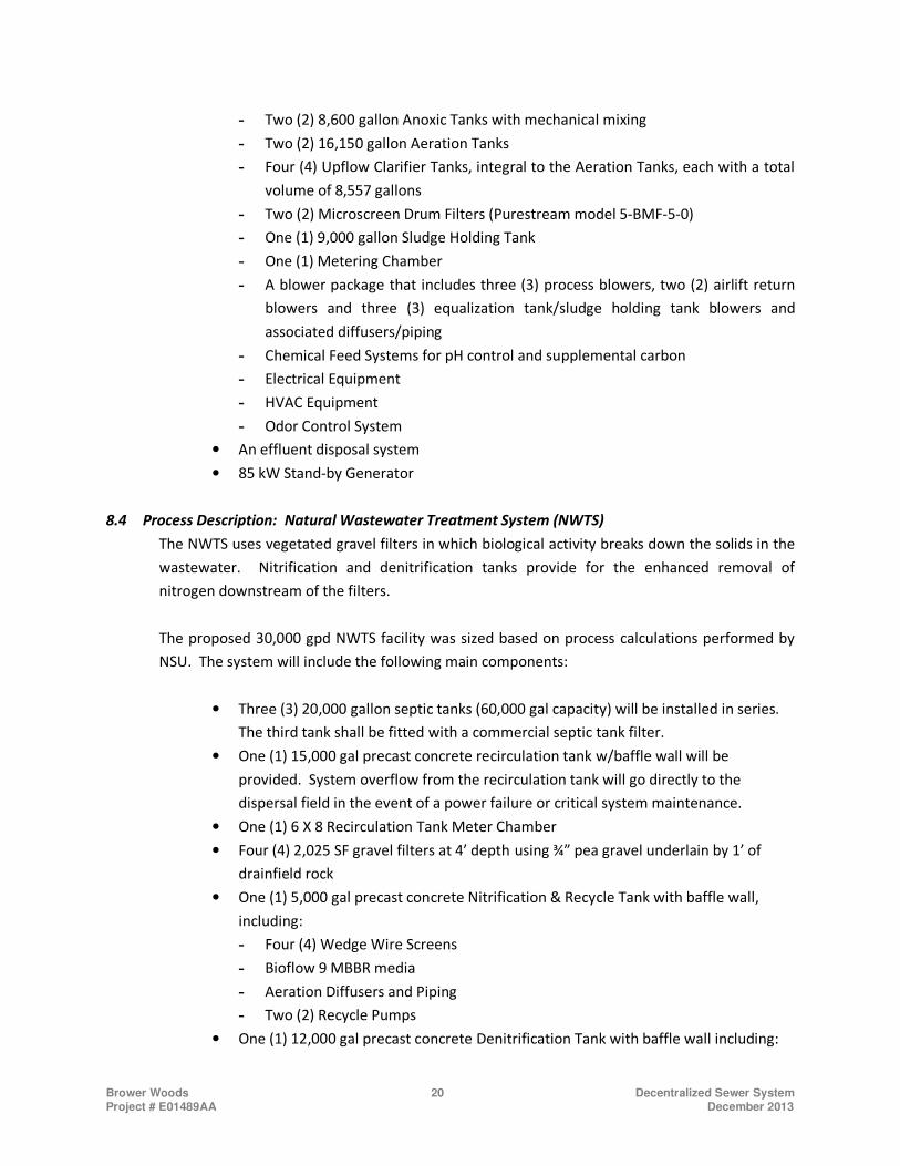
Brower Woods 20 Decentralized Sewer System Project # E01489AA December 2013
- Two (2) 8,600 gallon Anoxic Tanks with mechanical mixing
- Two (2) 16,150 gallon Aeration Tanks
- Four (4) Upflow Clarifier Tanks, integral to the Aeration Tanks, each with a total
volume of 8,557 gallons
- Two (2) Microscreen Drum Filters (Purestream model 5-BMF-5-0)
- One (1) 9,000 gallon Sludge Holding Tank
- One (1) Metering Chamber
- A blower package that includes three (3) process blowers, two (2) airlift return
blowers and three (3) equalization tank/sludge holding tank blowers and
associated diffusers/piping
- Chemical Feed Systems for pH control and supplemental carbon
- Electrical Equipment
- HVAC Equipment
- Odor Control System
• An effluent disposal system
• 85 kW Stand-by Generator
8.4 Process Description: Natural Wastewater Treatment System (NWTS)
The NWTS uses vegetated gravel filters in which biological activity breaks down the solids in the
wastewater. Nitrification and denitrification tanks provide for the enhanced removal of
nitrogen downstream of the filters.
The proposed 30,000 gpd NWTS facility was sized based on process calculations performed by
NSU. The system will include the following main components:
• Three (3) 20,000 gallon septic tanks (60,000 gal capacity) will be installed in series.
The third tank shall be fitted with a commercial septic tank filter.
• One (1) 15,000 gal precast concrete recirculation tank w/baffle wall will be
provided. System overflow from the recirculation tank will go directly to the
dispersal field in the event of a power failure or critical system maintenance.
• One (1) 6 X 8 Recirculation Tank Meter Chamber
• Four (4) 2,025 SF gravel filters at 4’ depth using ¾” pea gravel underlain by 1’ of
drainfield rock
• One (1) 5,000 gal precast concrete Nitrification & Recycle Tank with baffle wall,
including:
- Four (4) Wedge Wire Screens
- Bioflow 9 MBBR media
- Aeration Diffusers and Piping
- Two (2) Recycle Pumps
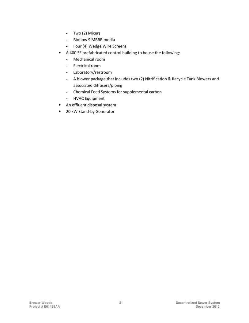
• One (1) 12,000 gal precast concrete Denitrification Tank with baffle wall including:
Brower Woods 21 Decentralized Sewer System Project # E01489AA December 2013
- Two (2) Mixers
- Bioflow 9 MBBR media
- Four (4) Wedge Wire Screens
• A 400 SF prefabricated control building to house the following:
- Mechanical room
- Electrical room
- Laboratory/restroom
- A blower package that includes two (2) Nitrification & Recycle Tank Blowers and
associated diffusers/piping
- Chemical Feed Systems for supplemental carbon
- HVAC Equipment
• An effluent disposal system
• 20 kW Stand-by Generator
Brower Woods 22 Decentralized Sewer System Project # E01489AA December 2013
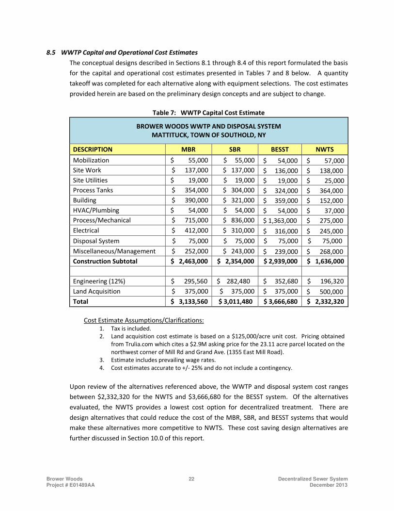
8.5 WWTP Capital and Operational Cost Estimates
The conceptual designs described in Sections 8.1 through 8.4 of this report formulated the basis
for the capital and operational cost estimates presented in Tables 7 and 8 below. A quantity
takeoff was completed for each alternative along with equipment selections. The cost estimates
provided herein are based on the preliminary design concepts and are subject to change.
Table 7: WWTP Capital Cost Estimate
BROWER WOODS WWTP AND DISPOSAL SYSTEM
MATTITUCK, TOWN OF SOUTHOLD, NY
DESCRIPTION MBR SBR BESST NWTS
Mobilization $ 55,000 $ 55,000 $ 54,000 $ 57,000
Site Work $ 137,000 $ 137,000 $ 136,000 $ 138,000
Site Utilities $ 19,000 $ 19,000 $ 19,000 $ 25,000
Process Tanks $ 354,000 $ 304,000 $ 324,000 $ 364,000
Building $ 390,000 $ 321,000 $ 359,000 $ 152,000
HVAC/Plumbing $ 54,000 $ 54,000 $ 54,000 $ 37,000
Process/Mechanical $ 715,000 $ 836,000 $ 1,363,000 $ 275,000
Electrical $ 412,000 $ 310,000 $ 316,000 $ 245,000
Disposal System $ 75,000 $ 75,000 $ 75,000 $ 75,000
Miscellaneous/Management $ 252,000 $ 243,000 $ 239,000 $ 268,000
Construction Subtotal $ 2,463,000 $ 2,354,000 $ 2,939,000 $ 1,636,000
Engineering (12%) $ 295,560 $ 282,480 $ 352,680 $ 196,320
Land Acquisition $ 375,000 $ 375,000 $ 375,000 $ 500,000
Total $ 3,133,560 $ 3,011,480 $ 3,666,680 $ 2,332,320
Cost Estimate Assumptions/Clarifications: 1. Tax is included.
2. Land acquisition cost estimate is based on a $125,000/acre unit cost. Pricing obtained
from Trulia.com which cites a $2.9M asking price for the 23.11 acre parcel located on the
northwest corner of Mill Rd and Grand Ave. (1355 East Mill Road).
3. Estimate includes prevailing wage rates.
4. Cost estimates accurate to +/- 25% and do not include a contingency.
Upon review of the alternatives referenced above, the WWTP and disposal system cost ranges
between $2,332,320 for the NWTS and $3,666,680 for the BESST system. Of the alternatives
evaluated, the NWTS provides a lowest cost option for decentralized treatment. There are
design alternatives that could reduce the cost of the MBR, SBR, and BESST systems that would
make these alternatives more competitive to NWTS. These cost saving design alternatives are
further discussed in Section 10.0 of this report.
Brower Woods 23 Decentralized Sewer System Project # E01489AA December 2013
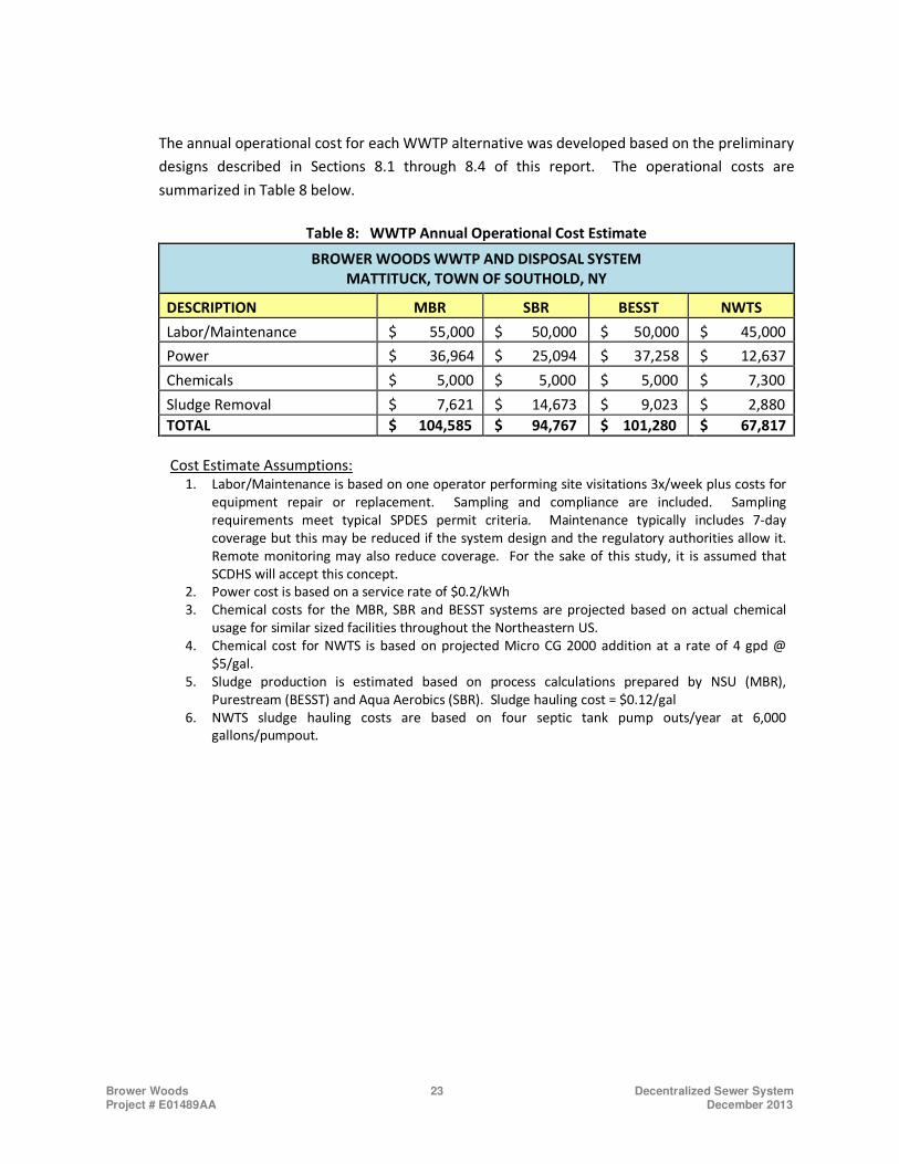
The annual operational cost for each WWTP alternative was developed based on the preliminary
designs described in Sections 8.1 through 8.4 of this report. The operational costs are
summarized in Table 8 below.
Table 8: WWTP Annual Operational Cost Estimate
BROWER WOODS WWTP AND DISPOSAL SYSTEM
MATTITUCK, TOWN OF SOUTHOLD, NY
DESCRIPTION MBR SBR BESST NWTS
Labor/Maintenance $ 55,000 $ 50,000 $ 50,000 $ 45,000
Power $ 36,964 $ 25,094 $ 37,258 $ 12,637
Chemicals $ 5,000 $ 5,000 $ 5,000 $ 7,300
Sludge Removal $ 7,621 $ 14,673 $ 9,023 $ 2,880
TOTAL $ 104,585 $ 94,767 $ 101,280 $ 67,817
Cost Estimate Assumptions:
1. Labor/Maintenance is based on one operator performing site visitations 3x/week plus costs for
equipment repair or replacement. Sampling and compliance are included. Sampling
requirements meet typical SPDES permit criteria. Maintenance typically includes 7-day
coverage but this may be reduced if the system design and the regulatory authorities allow it.
Remote monitoring may also reduce coverage. For the sake of this study, it is assumed that
SCDHS will accept this concept.
2. Power cost is based on a service rate of $0.2/kWh
3. Chemical costs for the MBR, SBR and BESST systems are projected based on actual chemical
usage for similar sized facilities throughout the Northeastern US.
4. Chemical cost for NWTS is based on projected Micro CG 2000 addition at a rate of 4 gpd @
$5/gal.
5. Sludge production is estimated based on process calculations prepared by NSU (MBR),
Purestream (BESST) and Aqua Aerobics (SBR). Sludge hauling cost = $0.12/gal
6. NWTS sludge hauling costs are based on four septic tank pump outs/year at 6,000
gallons/pumpout.
Brower Woods 24 Decentralized Sewer System Project # E01489AA December 2013
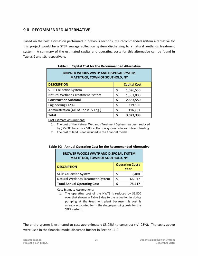
RECOMMENDED ALTERNATIVE 9.0
Based on the cost estimation performed in previous sections, the recommended system alternative for
this project would be a STEP sewage collection system discharging to a natural wetlands treatment
system. A summary of the estimated capital and operating costs for this alternative can be found in
Tables 9 and 10, respectively.
Table 9: Capital Cost for the Recommended Alternative
BROWER WOODS WWTP AND DISPOSAL SYSTEM
MATTITUCK, TOWN OF SOUTHOLD, NY
DESCRIPTION Capital Cost
STEP Collection System $ 1,026,550
Natural Wetlands Treatment System $ 1,561,000
Construction Subtotal $ 2,587,550
Engineering (12%) $ 319,506
Administration (4% of Const. & Eng.) $ 116,282
Total $ 3,023,338
Cost Estimate Assumptions:
1. The cost of the Natural Wetlands Treatment System has been reduced
by $75,000 because a STEP collection system reduces nutrient loading.
2. The cost of land is not included in the financial model.
Table 10: Annual Operating Cost for the Recommended Alternative
BROWER WOODS WWTP AND DISPOSAL SYSTEM
MATTITUCK, TOWN OF SOUTHOLD, NY
DESCRIPTION Operating Cost /
Year
STEP Collection System $ 9,400
Natural Wetlands Treatment System $ 66,017
Total Annual Operating Cost $ 75,417
Cost Estimate Assumptions:
1. The operating cost of the NWTS is reduced by $1,800
over that shown in Table 8 due to the reduction in sludge
pumping at the treatment plant because this cost is
already accounted for in the sludge pumping costs for the
STEP system.
The entire system is estimated to cost approximately $3.02M to construct (+/- 25%). The costs above
were used in the financial model discussed further in Section 11.0.
Brower Woods 25 Decentralized Sewer System Project # E01489AA December 2013
ALTERNATIVE COST SAVINGS 10.0
The wastewater treatment and collection systems presented in this report were designed based on
standard practice and Suffolk County requirements. There are, however, opportunities for substantial
cost savings if specific requirements were modified. These cost saving measures are described in more
detail below.
1. Locate Pre-treatment Tankage Outside of Building – Suffolk County requires that wastewater
treatment tankage be located within a building in order for to obtain a 150 foot setback to
property lines, otherwise a 350 foot setback would be required. If the trash trap, equalization
tank and/or sludge holding tank may be located outside of the building while allowing for a 150
foot setback, the cost savings resulting from a reduced building footprint could be
approximately $100,000 for the MBR, SBR and BESST systems.
2. Eliminate the Mechanical Room – Suffolk County requires that equipment such as the blowers
and permeate pumps be located in a separate mechanical room. If this equipment could be
placed on top of the process tankage, the building footprint and the amount of piping would be
reduced, thereby resulting in a cost savings of approximately $75,000 for the MBR and BESST
systems. This type of configuration is appropriate for the small treatment systems (Q < 100,000
gpd).
3. Packaged Steel Tank Construction – Suffolk County recently has required that all process
tankage be of concrete construction. For this size treatment plant, many manufacturers now
offer package plants using steel tanks. These systems can be delivered to the site and installed
on a concrete pad with minimal additional construction required. This could significantly reduce
the design and construction costs for the MBR and BESST systems.
For example, a 30,000 gpd packaged BESST system constructed of steel tanks has the potential
to reduce cost by $500,000. Another example is a 25,000 gpd packaged MBR system that was
recently installed in PA for a total construction cost of approximately $1.2M. The MBR system in
PA was a single train facility, which is allowed in states such as PA, VA, DE, etc. for flows under
50,000 gpd, and shows how steel packaged systems can be cost effective at facilities with lower
design capacities.
4. Sharing LPS Pumping Stations – This evaluation considers that each home connected to low
pressure wastewater collection system would have its own individual pumping station.
However, each simplex station has a 700 gpd capacity which is suitable to serve up to two single
family homes. If the pumping units were owned by a utility so that ownership and maintenance
Brower Woods 26 Decentralized Sewer System Project # E01489AA December 2013
conflicts are eliminated, two homes can be connected to each pump station. Reducing by half
the number of pump stations and lateral connections to the street would reduce the cost of the
pressure collection system by approximately $320,000.
5. Connecting Additional Customers – Connecting additional users to the treatment plant will
reduce the per user cost. The properties evaluated for the treatment plant location have
adequate area for a larger system and are located centrally to the surrounding developments. If
this option is considered during the design phase, the treatment facility could be designed to
allow for future expansion. The magnitude of the cost savings will depend on which treatment
plant option is chosen and how many additional customers will be connected.
OWNERSHIP STRUCTURE AND FINANCING 11.0
Development and financing of small-scale decentralized wastewater infrastructure has historically been
challenging in Suffolk County. Most municipalities do not have the expertise or the resources to
efficiently develop and manage dispersed wastewater infrastructure. Also many municipalities as well
as Suffolk County have been exploring innovative approaches to delivering decentralized wastewater
infrastructure. Therefore, this study will review alternative and innovative public private partnership
approaches that are successfully working in other states such as New Jersey. These approaches leverage
the expertise and capital of a private entity that specializes in deploying and managing decentralized
wastewater infrastructure and harnesses a municipality’s access to low cost debt, ability to assess fees
to its residents and legal right to build infrastructure in public rights of way.
Public Private Partnership – An alternative to the historical approach used in Suffolk County would be to
form a public private partnership that would entail the local municipality and a private entity jointly
funding and implementing the project. This partnership can take several forms (i.e. sewer maintenance
district), but generally harnesses the municipality’s access to low costs debt and leverages some amount
of capital from the private entity. The private entity would be responsible to turnkey the design, build
and/or long term operations of the system. This approach has been used to some extent in New York as
well as other states such as New Jersey and Massachusetts.
It is critical that the public private partnership leverage as much grant and incentive funding as possible
in order to reduce costs to the residents. There are many different potential funding scenarios with
different combinations of grants, municipal debt and private equity. The following summarizes a few
funding scenarios and their estimated impact on user fees per customer. It is important to note that
these economics assume the costs are spread over 100 users. If alternatively the costs were allocated to
all customers of the town (households and commercial), then the individual cost per user would be
significantly reduced.

Brower Woods 27 Decentralized Sewer System Project # E01489AA December 2013
Table 11: Annual User Fees
Funding Options
User Fee*
Brower Woods Only
($/year/customer)
User Fee*
Entire Community**
($/year/customer)
Connected
Customer
Other
Customer
100% Municipal Debt Financing $2,057 $500 $82
100% Grant Financing $754 $500 $13
80% Grant / 20% Private Equity $1,621 $500 $59
* The user fees are estimates based on certain financial assumptions. Administrative costs for legal services,
insurance, billing and collections were not included. A cost of capital of 15% is included in the option using
private equity.
** Assumes 2,000 users in the Town of Mattituck based on recent demographic and parcel data and reasonable
estimates. The 100 connected users pay a flat fee of $500 per year. The remaining cost is divided equally
among the other 1,900 customers.
RECOMMENDATIONS FOR POLICY AND REGULATORY CHANGE 12.0
A few approaches could be used to implement Public Private Partnerships for sewer systems in Suffolk
County. There are models from other states that have been used successfully and could be applied in
Suffolk County. Further discussion would be needed with the State of New York and Suffolk County
DPW to determine whether this type of approach could be implemented under current regulations. The
State of New York has not historically allowed Design-Build projects, but recent efforts having yielded
limited acceptance for certain projects conducted by DOT, Parks, DEC and a few other State Agencies.
CONCLUSIONS 13.0
The wastewater generated by the Brower Woods community in Mattituck, NY can be treated cost
effectively via a decentralized collection system and wastewater treatment plant located near the
community. Assuming an average daily flow of 30,000 gpd, a STEP collection system with a Natural
Wetlands Treatment System would result in a drastic reduction in the total amount of pollutants
discharged each year. Such a system would reduce the discharge of BOD to local waterways by 23,892
lbs, TN by 5,016 lbs, and TSS by 25,990 lbs annually and provide immense environmental benefit to the
community, Mattituck Inlet, and the Long Island Sound.
* * *
APPENDIX A
DRAWINGS AND FIGURES
FIGURE 1. SEWER SERVICE AREA
FIGURE 2. TAX MAP
FIGURE 3. ELEVATION
FIGURE 4. COMBINED GRAVITY/LPS COLLECTION SYSTEM – AERIAL
FIGURE 5. COMBINED GRAVITY/LPS COLLECTION SYSTEM – ELEVATION
FIGURE 6. WWTP SITE LOCATION
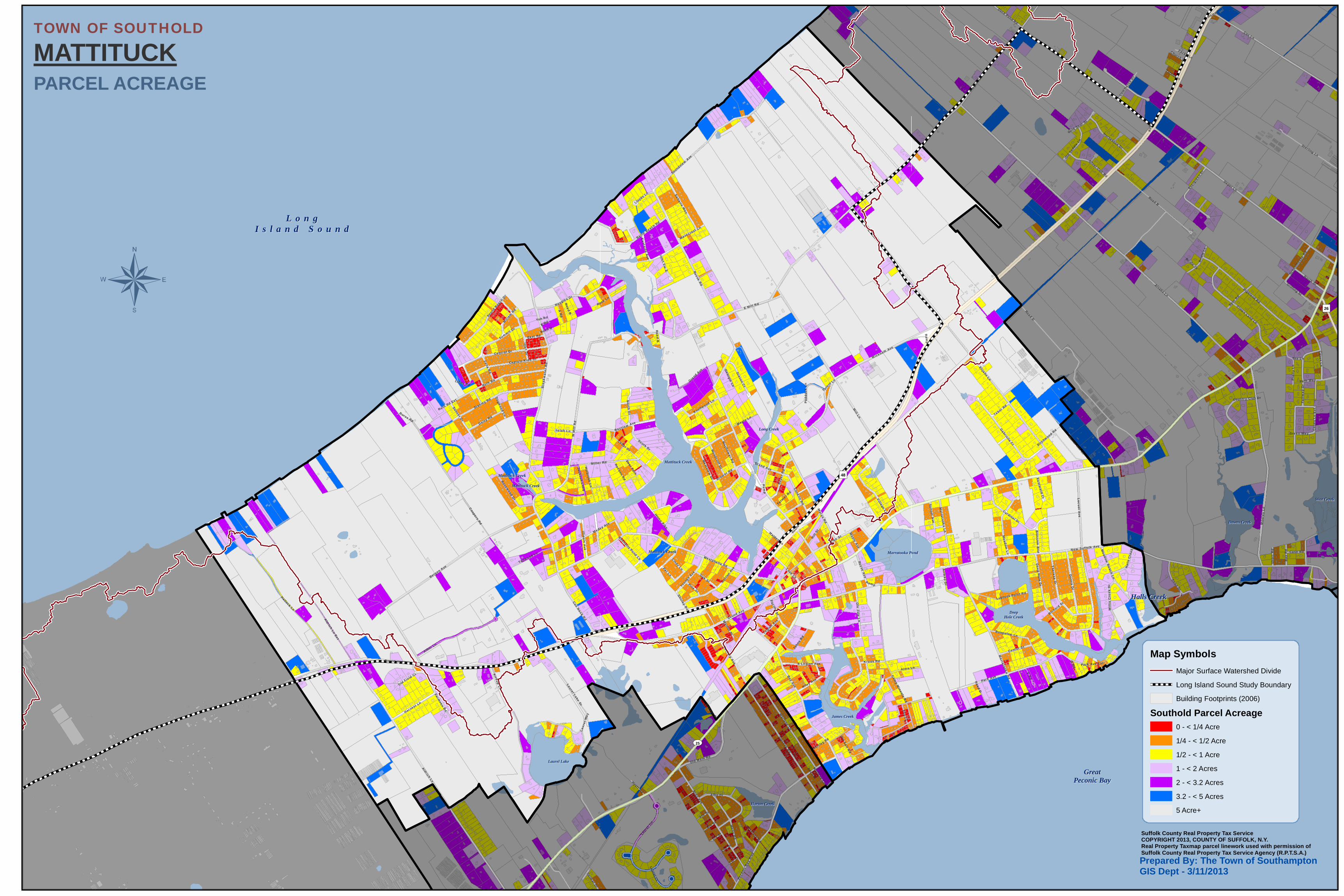
TOWN OF SOUTHOLD MAPPING
• Parcel Acreage
• Influence Zones
• Soils – Drainage Class
• Ground Water Depth
• Impaired Water
SEW
ER SE
RVIC
E AR
EAPE
CONI
C GR
EEN
GROW
THMA
TTITU
CK, L
ONG
ISLAN
D, N
EW YO
RK
LegendSewer Service Area
ParcelNot in SSAStructureVacant
0 200 400100Feet
µ
Date: 10/1/2013
Designed By: DCSDrawn By: ACH
Checked By: DCSProject: E01489AA
Figure: 1Rev:Scale: 1 '' = 400 '
2 CLE
RICO
LAN
E, SU
ITE
1HI
LLSB
OROU
GH, N
EW JE
RSEY
088
44PH
ONE:
(908
) 359
-5501
FAX:
(908
) 359
-8286
Mattituck Creek
Long Creek
Wickham Ave
Grand Ave
Bayer Rd
Woodcliff Dr
Westp
halia
Rd
Route 48
Greton Ct
Brower Rd
Conk
lin R
d
Knollwood Ln
Maple Ln
Home Pike
Westview Dr
Marys Rd
Mayflower Rd
Farmer Rd
South
Dr
Lesters Rd
Georgia Ln
Love L
n
Bayview Ave
Brea
kwate
r Rd
Deer Dr
Maiden
Ln
Gran
d Ave
Route 48
A
B
C
D
1 53 42
TAX
MAP
PECO
NIC
GREE
N GR
OWTH
MATT
ITUCK
, LON
G ISL
AND,
NEW
YORK
Legend
ParcelHydrography
0 100 20050Feet
µ
Date: 10/1/2013
Designed By: DCSDrawn By: ACH
Checked By: DCSProject: E01489AA
Figure: 2Rev:Scale: 1 '' = 200 '
2 CLE
RICO
LAN
E, SU
ITE
1HI
LLSB
OROU
GH, N
EW JE
RSEY
088
44PH
ONE:
(908
) 359
-5501
FAX:
(908
) 359
-8286
B: 600L: 13000
B: 200L: 9002
B: 600L: 1000
B: 300L: 5000
B: 300L: 4001
B: 600L: 18000
B: 300L: 11005
B: 300L: 3001
B: 100L: 18000
B: 800L: 33000
B: 100L: 20001
B: 800L: 44001
B: 100L: 20002
B: 600L: 7000
B: 100
L: 1000
B: 800L: 1000
B: 100
L: 2500
0
B: 600L: 4000
B: 60
0L:
1900
0
B: 600L: 5000
B: 80
0L:
1000
1
B: 100L: 19000
B: 200L: 10002
B: 300L: 11004
B: 800L: 37000
B: 300L: 2000
B: 800
L: 3000
B: 70
0L:
1002
B: 100L: 5000
B: 300L: 9002
B: 800L: 38000
B: 600
L: 8000
B: 100L: 17000
B: 800
L: 34000
B: 300L: 6000
B: 700L: 22000
B: 800L: 2000
B: 70
0L:
1001
B: 60
0L:
9000
B: 100L: 4002
B: 100
L: 23000
B: 100
L: 4001B: 100
L: 22000B: 200L: 10001
B: 100
L: 21000
B: 100
L: 2400
0
B: 600
L: 17004
B: 600L: 3000
B: 800L: 17000
B: 200
L: 11000
B: 800L: 19000
B: 800L: 18000
B: 600
L: 17002
B: 700L: 3000
B: 100L: 3000
B: 100L: 2000
B: 600
L: 17003
B: 200
L: 12000
B: 300
L: 7000
B: 700L: 4000
B: 700L: 21000
B: 700
L: 11000
B: 70
0L:
2000
B: 800L: 32000
B: 800
L: 11000
B: 800L: 5000
B: 600L: 15000
B: 800L: 4000
B: 800L: 8000
B: 600
L: 20000
B: 800
L: 24000
B: 100L: 6000
B: 800
L: 13000B: 800
L: 12000
B: 800
L: 16000
B: 700L: 10000
B: 700L: 5000
B: 100L: 7000
B: 300L: 8000
B: 800L: 6000
B: 800L: 7000 B: 700L: 28000
B: 700L: 6000
B: 800
L: 15000
B: 300
L: 120
00
B: 700L: 7000
B: 800L: 42000
B: 600L: 14000
B: 700L: 8000
B: 100L: 14000
B: 800
L: 21000B: 800
L: 23000
B: 800L: 31000
B: 800L: 25000
B: 800
L: 14000
B: 800L: 39000
B: 100L: 15000
B: 800L: 41000
B: 800L: 29000
B: 800L: 28000
B: 800
L: 22000
B: 700L: 9000
B: 800L: 40000
B: 800L: 27000
B: 800
L: 20000
B: 800L: 26000
B: 100L: 8000
B: 800L: 30000
B: 300L: 14000
B: 600
L: 6000
B: 200
L: 13000
B: 700
L: 23000
B: 700
L: 24000
B: 700
L: 26000
B: 100L: 12000
B: 700
L: 25000
B: 700
L: 27000
B: 100L: 13000
B: 100L: 10000
B: 100L: 16000
B: 700
L: 14000
B: 700
L: 12000
B: 100L: 11000
B: 700
L: 20000
B: 700
L: 16000B: 700
L: 18000
B: 100L: 9000
B: 700
L: 13000
B: 700
L: 17000
B: 700
L: 15000
B: 700
L: 19000
B: 300
L: 13000
B: 200L: 14000 B: 300
L: 16000
B: 300L: 15000
Mattituck Creek
Long Creek
Grand Ave
Woodcliff Dr
Brower Rd
Maple Ln
Westview Dr Mayflower Rd
Brea
kwate
r Rd
A
B
C
D
1 53 42
ELEV
ATIO
NPE
CONI
C GR
EEN
GROW
THMA
TTITU
CK, L
ONG
ISLAN
D, N
EW YO
RK
0 100 20050Feet
µ
Date: 10/1/2013
Designed By: DCSDrawn By: ACH
Checked By: DCSProject: E01489AA
Figure: 3Rev:Scale: 1 '' = 200 '
2 CLE
RICO
LAN
E, SU
ITE
1HI
LLSB
OROU
GH, N
EW JE
RSEY
088
44PH
ONE:
(908
) 359
-5501
FAX:
(908
) 359
-8286
Mattituck Creek
Long Creek
Grand Ave
Woodcliff Dr
Brower Rd
Maple Ln
Westview Dr Mayflower Rd
Knollwood Ln
Brea
kwate
r Rd
515
10
20
25
30
35
35
35
5
3030
5
5
30
5
25
5
30
35
10
20
5
35
20
15
10
15
25
35
10
15
20
20
5
25
30
10
25
20
30
30
A
B
C
D
1 53 42Legend
ContourHydrography
COMB
INED
GRA
VITY/L
PSCO
LLEC
TION
SYST
EM A
ERIA
LBR
OWER
WOO
DSPE
CONI
C GR
EEN
GROW
THMA
TTITU
CK, L
ONG
ISLA
ND, N
EW Y
ORK
0 100 20050Feet
µ
Date: 10/11/2013
Designed By: JRDrawn By: ACH
Checked By: DCSProject: E0000AA
Figure: 4Rev:Scale: 1 '' = 200 '
2 CLE
RICO
LAN
E, SU
ITE
1HI
LLSB
OROU
GH, N
EW JE
RSEY
088
44PH
ONE:
(908
) 359
-5501
FAX:
(908
) 359
-8286
[Ú
!! 2
!! 2
!! 2
!! 2
!! 2
!! 2
!! 2
!! 2
!! 2
!! 2
!! 2
!! 2
!! 2
!! 2
!! 2
!! 2
!! 2
!! 2
!! 2
!! 2!! 2
Mattituck Creek
Long Creek
Grand Ave
Woodcliff Dr
Brower Rd
Westview Dr Mayflower Rd
Knollwood Ln
Maple Ln
Brea
kwate
r Rd
MH136 FT
MH1715 FT
MH1619 FT
MH1522 FT
MH1816 FT
MH527.1 FT
MH821.8 FT
MH723.6 FT
MH234.1 FT
MH427.2 FT
MH330.6 FT
MH917.1 FT
MH625.3 FT
MH2026.7 FT
MH1134.1 FT
MH1229.9 FT
MH1329.9 FT
MH1928.7 FT
MH1015.1 FT
MH2125.2 FT
MH1422.3 FT
A
B
C
D
1 53 42LegendManhole: MH1 R = 36FT!!2
Pump Station
[Ú
Gravity Main
Low Pressure Main
Force Main
Water
!! 2
!! 2
!! 2
!! 2
!! 2!! 2
!! 2
!! 2
!! 2
!! 2
!! 2
!! 2
!! 2
!! 2
!! 2
!! 2
!! 2
!! 2
!! 2
!! 2!! 2
[Ú
Mattituck Creek
Long CreekOVERVIEW

COMB
INED
GRA
VITY/L
PSCO
LLEC
TION
SYST
EM EL
EVAT
ION
BROW
ER W
OODS
PECO
NIC
GREE
N GR
OWTH
MATT
ITUCK
, LON
G IS
LAND
, NEW
YOR
K
0 100 20050Feet
µ
Date: 10/11/2013
Designed By: JRDrawn By: ACH
Checked By: DCSProject: E0000AA
Figure: 5Rev:Scale: 1 '' = 200 '
2 CLE
RICO
LAN
E, SU
ITE
1HI
LLSB
OROU
GH, N
EW JE
RSEY
088
44PH
ONE:
(908
) 359
-5501
FAX:
(908
) 359
-8286
[Ú
!! 2
!! 2
!! 2
!! 2
!! 2
!! 2
!! 2
!! 2
!! 2
!! 2
!! 2
!! 2
!! 2
!! 2
!! 2
!! 2
!! 2
!! 2
!! 2
!! 2!! 2
Mattituck Creek
Long Creek
Grand Ave
Woodcliff Dr
Brower Rd
Westview Dr Mayflower Rd
Knollwood Ln
Maple Ln
Brea
kwate
r Rd
MH: 136 FT
MH: 1715 FT
MH: 1619 FT
MH: 1522 FT
MH: 1816 FT
MH: 527.1 FT
MH: 821.8 FT
MH: 723.6 FT
MH: 234.1 FT
MH: 427.2 FT
MH: 330.6 FT
MH: 917.1 FT
MH: 625.3 FT
MH: 2026.7 FT
MH: 1134.1 FT
MH: 1229.9 FT
MH: 1329.9 FT
MH: 1928.7 FT
MH: 1015.1 FT
MH: 2125.2 FT
MH: 1422.3 FT
A
B
C
D
1 53 42LegendManhole: MH1 R = 36FT!!2
Pump Station
[Ú
Gravity Main
Low Pressure Main
Force Main
Contour
Water
!! 2
!! 2
!! 2
!! 2
!! 2!! 2
!! 2
!! 2
!! 2
!! 2
!! 2
!! 2
!! 2
!! 2
!! 2
!! 2
!! 2
!! 2
!! 2
!! 2!! 2
[Ú
Mattituck Creek
Long CreekOVERVIEW
WWTP
SITE
LOCA
TION
BROW
ER W
OODS
PECO
NIC
GREE
N GR
OWTH
MATT
ITUCK
, LON
G ISL
AND,
NEW
YORK
LegendForce Main
Min. Area for WWTP & Disposal
Proposed WWTP & Disposal Footprint
Potential Sites for WWTP and Disposal
Preserved Parcels
Parcel
0 200 400100Feet
µ
Date: 10/10/2013
Designed By: DCSDrawn By: ACH
Checked By: DCSProject: E01489AA
Figure: 6Rev:Scale: 1 '' = 400 '
2 CLE
RICO
LAN
E, SU
ITE
1HI
LLSB
OROU
GH, N
EW JE
RSEY
088
44PH
ONE:
(908
) 359
-5501
FAX:
(908
) 359
-8286
B: 100L: 1003
ac: 24.91B: 300
L: 12000ac: 23.11
B: 300L: 16000ac: 18.47
B: 100L: 2001
ac: 15.34
B: 400L: 1005ac: 10.1
B: 400L: 1003
ac: 10.45
0.28 ac
3.41 ac
5700 LF 4'' PVC
E Mill Rd
Reeve Rd
Grand Ave
Greton CtKnollwood Ln
North DrW Mi
ll Rd
Maple Ln
Sebastians Cv
Inlet Vw E
Oregon Rd
Bayview Ave
Harbor View Ave
Eastside Ave
Georgia Ln
Sea Aire Ln
Road B
Road B
A
B
C
D
1 53 42
Footprint Required For WWTP (0.28 Ac)
Minimum Area Required for WWTP and Disposal
(Includes 150' Setback to Property Line)
Laurel LakeLaurel Lake
GreatGreatPeconic BayPeconic Bay
Halls CreekHalls Creek
Marratooka PondMarratooka Pond
L o n gL o n gI s l a n d S o u n dI s l a n d S o u n d
Mattituck CreekMattituck Creek
West CreekWest Creek
James CreekJames Creek
DeepDeepHole CreekHole Creek
Downs CreekDowns Creek
Horton CreekHorton Creek
Long CreekLong Creek
Mattituck CreekMattituck Creek
Mattituck CreekMattituck Creek
Mattituck CreekMattituck Creek
UV25
Depot Ln
Alvahs Ln
Mill Ln
Orego
n Rd
Elijahs Ln
New Suffolk Ave
Road D
Aldrich Ln
Cox Ln
Wickham Ave
W M
ill
Rd
Sound Ave
Bay Ave
Bergen Ave
E Mill Rd
Westphalia Rd
Reeve Rd
Hallock Ln
Park Ave
Bre
akw
ate
r R
dPike St
Road B
Bray Ave
Ruth Rd
Kirkup Ln
Stanley Rd
Cox Neck R
d
Marys R
d
Sigsbee Rd
Aldrich Ln Ext
Coopers Rd
Highland Rd
Arbor Ln
Marlene Ln
Peco
nic
Bay
Blv
d
Marratooka R
d
Inlet D
r
Soundview A
ve
Fair
wa
y D
r
Miller Rd
Central Dr
Naugles Dr
Locust A
ve
Donn
a Dr
Gabriella Ct
Wells R
d
Love Ln
The
resa Dr
Meday Ave
Crown Land Ln
Bayview Ave
Ole Jule
Ln
Case s L n
Sterling Ln
Deep H
ole Dr
Old Main Rd
Factory Ave
Conklin R
d
Village Ln
Manor Hill Ln
Cardinal Dr
Laurel Lake Dr
Hort
on A
ve
Sunset Dr
Bungalow Ln
Bay
er R
d
Captain Kidd Dr
Moo
r es
Ln
Farmveu Rd
Hill
St
Dean Dr
Meadow
Beach Ln
Laur
el T
rl
Pr a
ity
Ln
Albo Dr
Marrat ook
a Ln
Saltaire Way
Harvest Ln
Summit Dr
Woodcliff D
r
North St
Daisy Rd
South Dr
Bailie Beach Rd
Laur
el W
ay
Greton C
t
Spur R
d
Oak St
Grand
Ave
Soun
d Bea
ch D
r
Griffing St
Horseshoe Dr
Mead
ow Ln
Ever
gree
n Dr
Pacific St
Brower Rd
A R
d
Youn
gs A
ve
Rosewood Dr
Cam
p Mineola R
d
Alois Ln
F Rd
Tallwood Ln
Center St
Bri
dle
Ln
Reeve Ave
Ramp
Cedar Dr
Luptons Point Rd
Knollwood Ln
Zena Rd
Nor th D
rBurus Rd
Silver Colt Rd
Miri
am R
d
Maple Ln
Illinois A
ve
Home Pike
Riley Ave
Pat Ln
Bay
Rd
Ai rw
ay D
r
Westview
Dr
Wil
lis
Cre
ek D
rPine St
Kraus Rd
Tuth
ill L
n
Bloss om
Bnd
Legi
on A
ve
Old Salt R
d
Scho
olho
use
Rd
E Legion Ave
Rout
e 48
East Rd
Old S
addl
e Ln
Sunset A
ve
Fay Ct
Country Club Dr
John
s Rd
Duck Pond Rd
Com
mer
ce D
r
Farm
er Rd
Inlet Vw
E
Mayflow
er Rd
Laurel Ct
Tabor Rd
Case Rd
Park Ave Ext
Hyatt Rd
Hal
ls C
reek
Dr
Gold Spur St
Jackson Lnd
g
G R
d
Shirley Rd
Selah Ln
Racoon Rd
Cindy Ln
Wavecrest Ln
Sh
ort
Rd
Lloyds L
n
Walnut Pl
Eastw
ard Ct
Delmar Dr
Georgia Ln
Holbrook Ln
Eastside A
ve
Maple A
ve
Path Way
Hobson Dr
Dogw
ood Ln
Rose Ln
Zacks Ln
Green Way
3rd St
Old Field Ct
Bennetts Pond Ln
Deer Path
E Rd
Church Ln
Pad
dock
Ln
Ca s
e s L
n E
xt
1st St
Richard St
Masters Rd
5th St
Bartley Rd
2nd St
Linda Rd
Tee Ln
4th St
Birchwood R
d
Maiden Ln
Bridle Ct
Yoh Rd
Ruth Rd Ext
Tuthill Ln
Ramp
Ram
p
Road D
Sound Ave
Marlene Ln
Grand Ave
Road D
Ramp
Ramp
Ramp
Roa
d B
Ram
p
Ram
p
Road D
Road B
")48
")26
TOWN OF SOUTHOLD
MATTITUCK
Map SymbolsMajor Surface Watershed Divide
Long Island Sound Study Boundary
Building Footprints (2006)
Southold Parcel Acreage0 - < 1/4 Acre
1/4 - < 1/2 Acre
1/2 - < 1 Acre
1 - < 2 Acres
2 - < 3.2 Acres
3.2 - < 5 Acres
5 Acre+
PARCEL ACREAGE
¬
Suffolk County Real Property Tax ServiceCOPYRIGHT 2013, COUNTY OF SUFFOLK, N.Y.Real Property Taxmap parcel linework used with permission ofSuffolk County Real Property Tax Service Agency (R.P.T.S.A.)Prepared By: The Town of Southampton GIS Dept - 3/11/2013
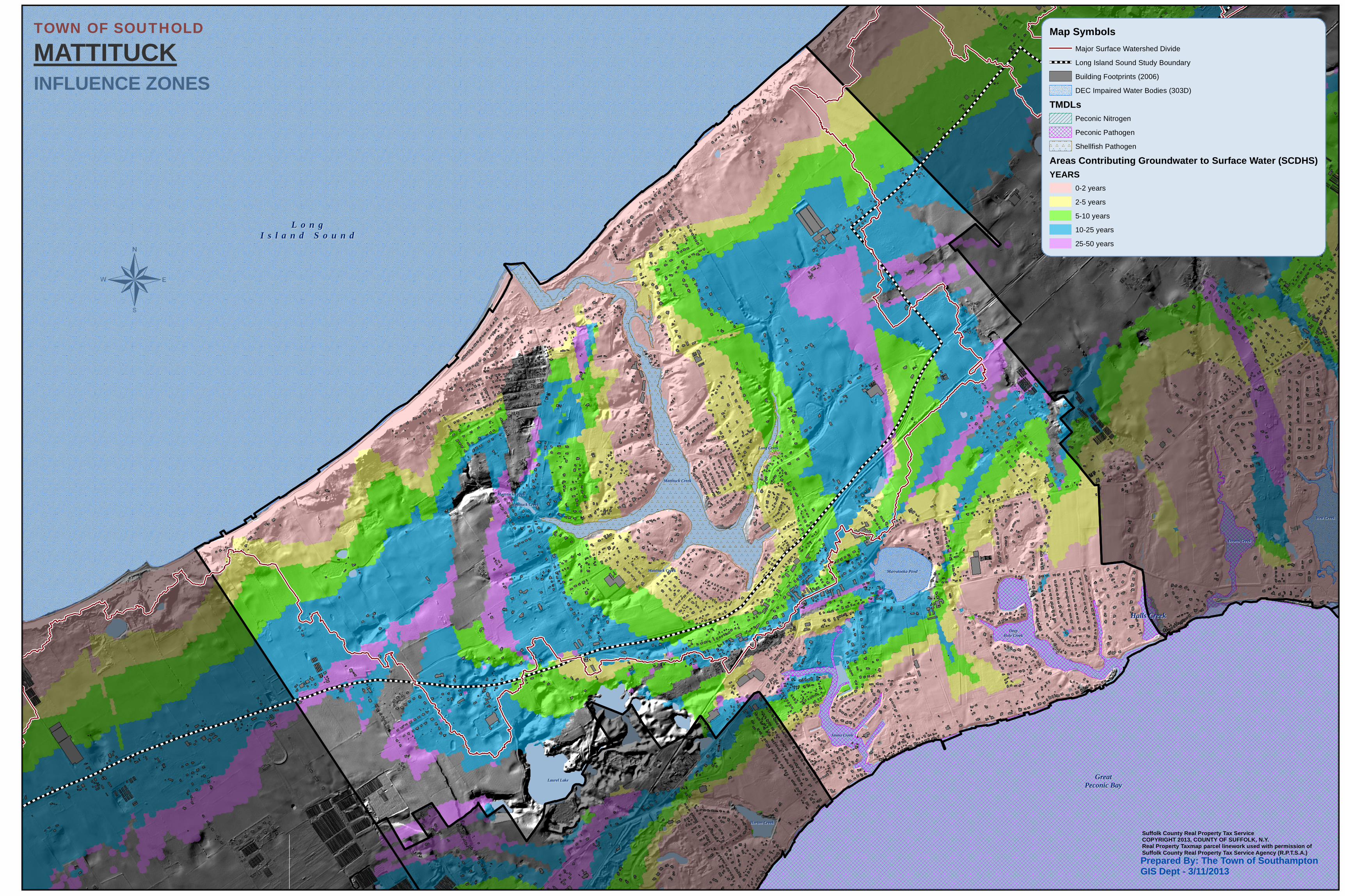
Mattituck CreekMattituck Creek
West CreekWest Creek
James CreekJames Creek
DeepDeepHole CreekHole Creek
Downs CreekDowns Creek
Horton CreekHorton Creek
Long CreekLong Creek
Mattituck CreekMattituck Creek
Mattituck CreekMattituck Creek
Mattituck CreekMattituck Creek
Laurel LakeLaurel Lake GreatGreatPeconic BayPeconic Bay
Halls CreekHalls Creek
Marratooka PondMarratooka Pond
L o n gL o n gI s l a n d S o u n dI s l a n d S o u n d
TOWN OF SOUTHOLD
MATTITUCKMap Symbols
Major Surface Watershed Divide
Long Island Sound Study Boundary
Building Footprints (2006)
DEC Impaired Water Bodies (303D)
TMDLsPeconic Nitrogen
Peconic Pathogen
Shellfish Pathogen
Areas Contributing Groundwater to Surface Water (SCDHS)YEARS
0-2 years
2-5 years
5-10 years
10-25 years
25-50 years
INFLUENCE ZONES
¬
Suffolk County Real Property Tax ServiceCOPYRIGHT 2013, COUNTY OF SUFFOLK, N.Y.Real Property Taxmap parcel linework used with permission ofSuffolk County Real Property Tax Service Agency (R.P.T.S.A.)Prepared By: The Town of Southampton GIS Dept - 3/11/2013
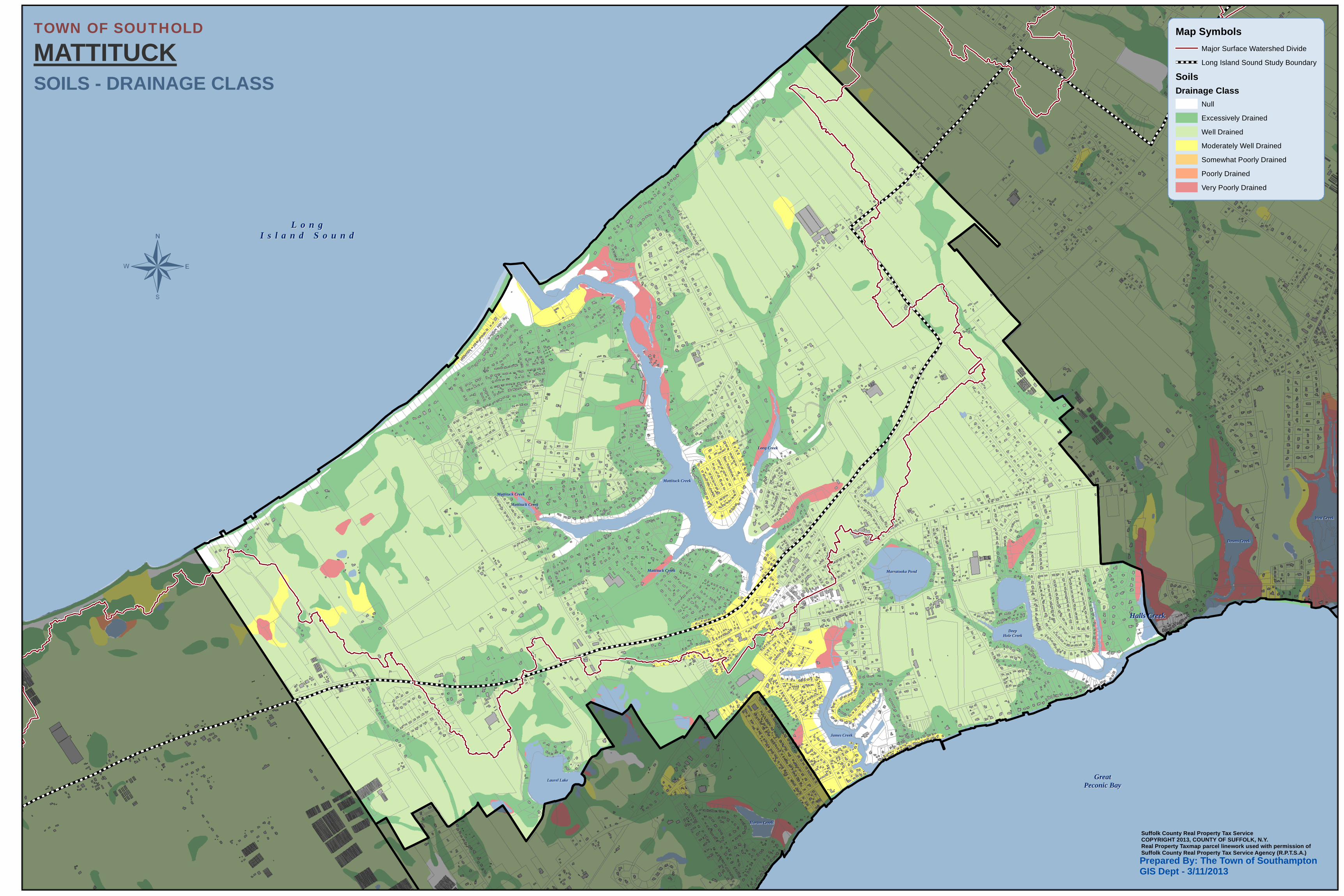
Mattituck CreekMattituck Creek
West CreekWest Creek
James CreekJames Creek
DeepDeepHole CreekHole Creek
Downs CreekDowns Creek
Horton CreekHorton Creek
Long CreekLong Creek
Mattituck CreekMattituck Creek
Mattituck CreekMattituck Creek
Mattituck CreekMattituck Creek
Laurel LakeLaurel Lake GreatGreatPeconic BayPeconic Bay
Halls CreekHalls Creek
Marratooka PondMarratooka Pond
L o n gL o n gI s l a n d S o u n dI s l a n d S o u n d
TOWN OF SOUTHOLD
MATTITUCKMap Symbols
Major Surface Watershed Divide
Long Island Sound Study Boundary
SoilsDrainage Class
Null
Excessively Drained
Well Drained
Moderately Well Drained
Somewhat Poorly Drained
Poorly Drained
Very Poorly Drained
SOILS - DRAINAGE CLASS
¬
Suffolk County Real Property Tax ServiceCOPYRIGHT 2013, COUNTY OF SUFFOLK, N.Y.Real Property Taxmap parcel linework used with permission ofSuffolk County Real Property Tax Service Agency (R.P.T.S.A.)Prepared By: The Town of Southampton GIS Dept - 3/11/2013
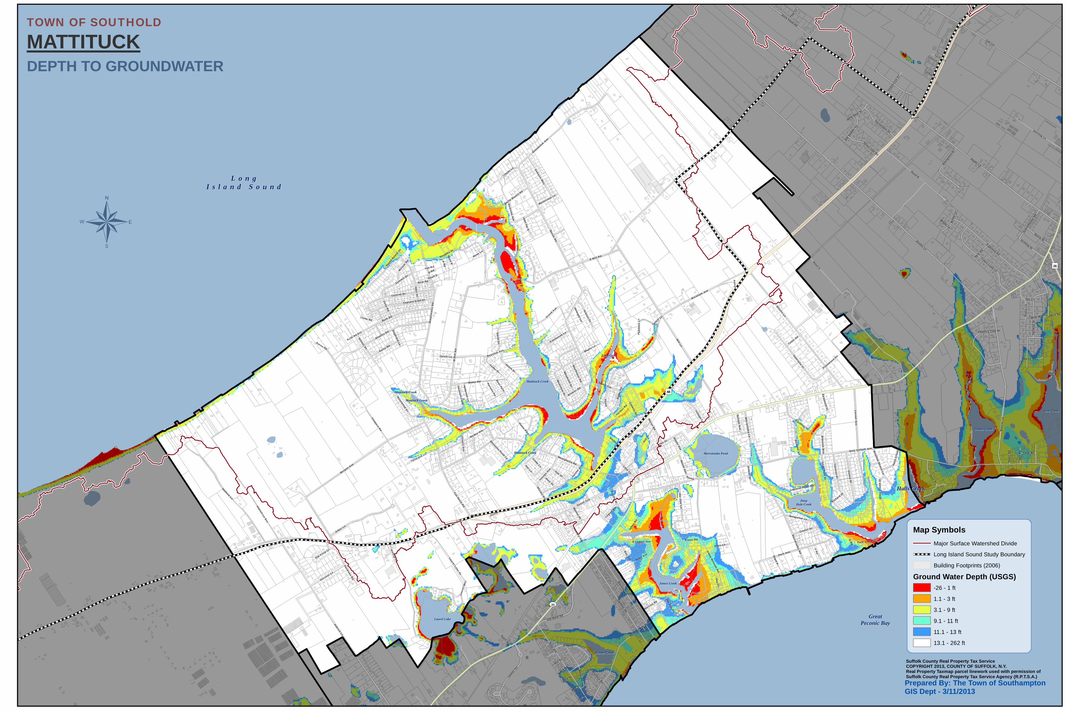
Mattituck CreekMattituck Creek
West CreekWest Creek
James CreekJames Creek
DeepDeepHole CreekHole Creek
Downs CreekDowns Creek
Horton CreekHorton Creek
Long CreekLong Creek
Mattituck CreekMattituck Creek
Mattituck CreekMattituck Creek
Mattituck CreekMattituck Creek
Laurel LakeLaurel Lake GreatGreatPeconic BayPeconic Bay
Halls CreekHalls Creek
Marratooka PondMarratooka Pond
L o n gL o n gI s l a n d S o u n dI s l a n d S o u n d
UV25
Depot Ln
Orego
n Rd
Alvahs Ln
Mill Ln
Elijahs Ln
New Suffolk Ave
Road D
Cox Ln
Aldrich Ln
Wickham Ave
W M
ill
Rd
Sound Ave
Bay Ave
Bergen Ave
E Mill Rd
Westphalia Rd
Reeve Rd
Hallock Ln
Park Ave
Bre
akw
ate
r R
d
Pike St
Road B
Bray Ave
Ruth Rd
Kirkup Ln
Stanley Rd
Cox Neck R
d
Marys Rd
Sigsbee Rd
Aldrich Ln Ext
Coopers Rd
Highland Rd
Arbor Ln
Marlene Ln
Marratooka R
d
Inlet D
r
Soundview A
ve
Fair
wa
y D
r
Miller Rd
Peconic Bay Blvd
Central Dr
Naugles Dr
Locust Ave
Donn
a Dr
Gabriella Ct
Wells R
d
Love Ln
Theresa D
r
Meday Ave
Crown Land Ln
Sterling Ln
Bayview Ave
Ole Jule
Ln
Case s L n
Deep
Hole D
r
Old Main Rd
Factory Ave
Conklin R
d
Village Ln
Manor Hill Ln
Cardinal Dr
Laurel Lake Dr
Hort
on A
ve
Sunset Dr
Bungalow Ln
Bay
er R
d
Captain Kidd Dr
Moo
r es
Ln
Farmveu Rd
Hill
St
Dean Dr
Meadow
Beach Ln
Laur
el T
rl
Pr a
ity
Ln
Albo Dr
Duck Pond Rd
Marrat ook
a Ln
Saltaire Way
Harvest Ln
Summit Dr
Woodcliff D
r
North St
Daisy Rd
South Dr
Bailie Beach Rd
Laur
el W
ay
Greton C
t
Spur R
d
Oak St
Grand
Ave
Soun
d Bea
ch D
r
Griffing St
Horseshoe Dr
Meadow
Ln
Ever
gree
n Dr
Pacific St
Brower Rd
A R
d
Youn
gs A
ve
Rosewood D
r
Cam
p Mineola R
d
Alois Ln
F Rd
Tallwood Ln
Center St
Bri
dle
Ln
Reeve Ave
Ramp
Cedar Dr
Luptons Point Rd
Knollwood Ln
Zena Rd
Nor th D
rBurus Rd
Silver Colt Rd
Miri
am R
d
Maple Ln
Illinois A
ve
Home Pike
Riley Ave
Pat Ln
Bay
Rd
Ai rw
ay Dr
Westview
Dr
Wil
lis
Cre
ek D
rPine St
Kraus Rd
Tuth
ill L
n
Bloss om
Bnd
Legi
on A
ve
Old Salt R
d
Scho
olho
use
Rd
E Legion Ave
Rout
e 48
East Rd
Old S
addl
e Ln
Sunset A
ve
Fay Ct
Country Club Dr
John
s Rd
Com
mer
ce D
r
Farm
er Rd
Inlet Vw
E
Mayflow
er Rd
Tabor Rd
Thar
Ln
Case Rd
Park Ave Ext
Hyatt Rd
Hal
ls C
reek
Dr
Gold Spur St
Jackson Lnd
g
G R
d
Shirley Rd
Selah Ln
Racoon Rd
Cindy Ln
Wavecrest Ln
Sh
ort
Rd
Lloyds L
n
Walnut Pl
Eastw
ard Ct
Georgia Ln
Holbrook Ln
Eastside A
ve
Maple A
ve
Path Way
Hobson Dr
Dogw
ood Ln
Rose Ln
Zacks Ln
Green Way
3rd St
Old Field Ct
Bennetts Pond Ln
Deer Path
E Rd
Church Ln
Pad
dock
Ln
Cedars Rd
Cas
e s L
n E
xt
1st St
Richard S
t
Masters Rd
5th St
Bartley Rd
2nd St
Linda Rd
Tee Ln
4th St
Birchwood R
d
Maiden Ln
Bridle Ct
Yoh Rd
Ruth Rd Ext
Tuthill Ln
Ramp
Grand Ave
Ramp
Ramp
Sound Ave
Ram
p
Road D
Ramp
Ramp
Ramp
Roa
d B
Ram
p
Ramp
Road D
Road B
")48
")26
TOWN OF SOUTHOLD
MATTITUCK
Map SymbolsMajor Surface Watershed Divide
Long Island Sound Study Boundary
Building Footprints (2006)
Ground Water Depth (USGS)-26 - 1 ft
1.1 - 3 ft
3.1 - 9 ft
9.1 - 11 ft
11.1 - 13 ft
13.1 - 262 ft
DEPTH TO GROUNDWATER
¬
Suffolk County Real Property Tax ServiceCOPYRIGHT 2013, COUNTY OF SUFFOLK, N.Y.Real Property Taxmap parcel linework used with permission ofSuffolk County Real Property Tax Service Agency (R.P.T.S.A.)Prepared By: The Town of Southampton GIS Dept - 3/11/2013
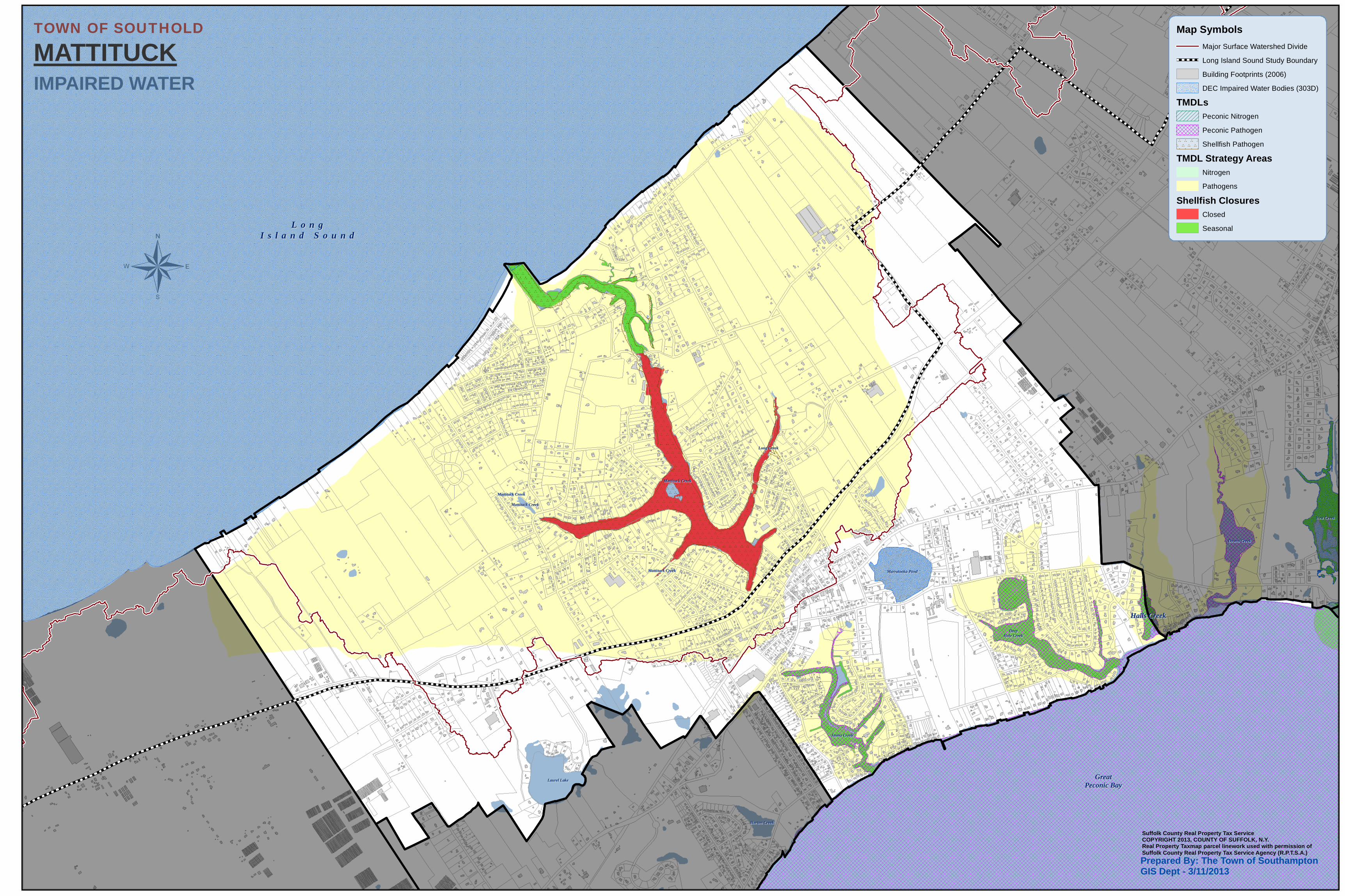
Mattituck CreekMattituck Creek
West CreekWest Creek
James CreekJames Creek
DeepDeepHole CreekHole Creek
Downs CreekDowns Creek
Horton CreekHorton Creek
Long CreekLong Creek
Mattituck CreekMattituck Creek
Mattituck CreekMattituck Creek
Mattituck CreekMattituck Creek
Laurel LakeLaurel Lake GreatGreatPeconic BayPeconic Bay
Halls CreekHalls Creek
Marratooka PondMarratooka Pond
L o n gL o n gI s l a n d S o u n dI s l a n d S o u n d
TOWN OF SOUTHOLD
MATTITUCKMap Symbols
Major Surface Watershed Divide
Long Island Sound Study Boundary
Building Footprints (2006)
DEC Impaired Water Bodies (303D)
TMDLsPeconic Nitrogen
Peconic Pathogen
Shellfish Pathogen
TMDL Strategy AreasNitrogen
Pathogens
Shellfish ClosuresClosed
Seasonal
IMPAIRED WATER
¬
Suffolk County Real Property Tax ServiceCOPYRIGHT 2013, COUNTY OF SUFFOLK, N.Y.Real Property Taxmap parcel linework used with permission ofSuffolk County Real Property Tax Service Agency (R.P.T.S.A.)Prepared By: The Town of Southampton GIS Dept - 3/11/2013
APPENDIX B
WWTP LAYOUTS
NTWS AND ADVANTEX PROCESS FLOW DIAGRAMS
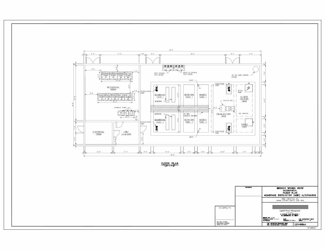
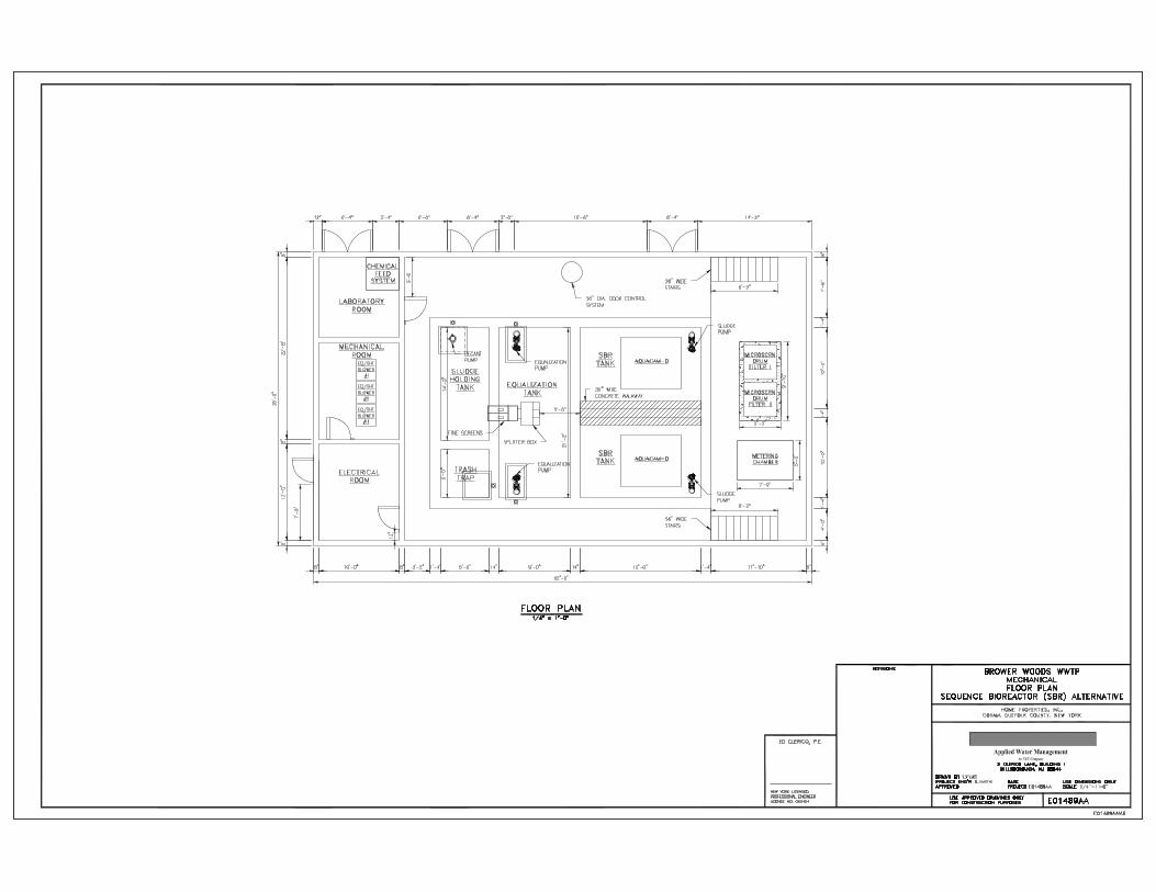

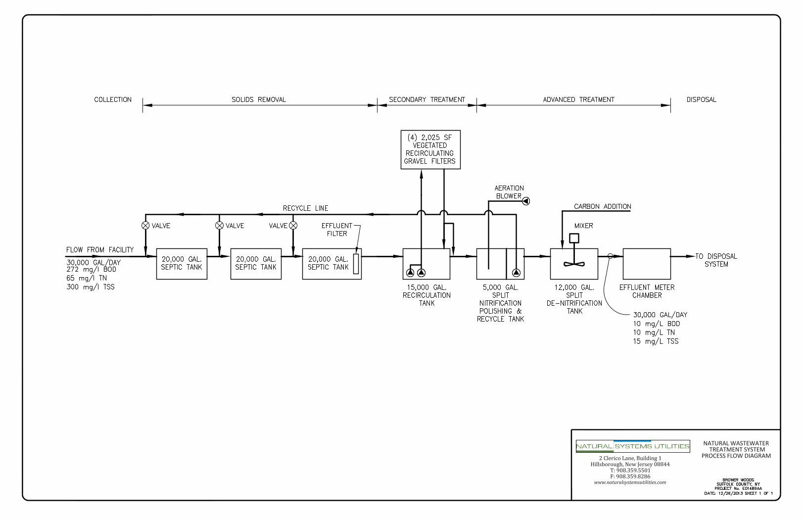
2 Clerico Lane, Building 1Hillsborough,NewJersey08844
T: 908.359.5501F:908.359.8286
www.naturalsystemsutilities.com
NATURAL WASTEWATER TREATMENT SYSTEM
PROCESS FLOW DIAGRAM