Broadband via TV far flung
28
REMOTE BROADBAND SUBMISSION 27 JUNE 2008 PAGE 1 OF 3 Careful spectrum planning and long-term investment could see more Australians receive the benefits of broadband. The Far Flung network would enable widespread weather monitoring and water management applications. The Australian National University’s research can now be implemented in a national deployment that supplements the NBN participation coverage. The intellectual property of the resulting “cognitive” radio sensing technology would be applicable in world markets and represents an export opportunity. far-flung (adj.) extending over a great distance widely disbursed or distributed. • Complete R&D for optimal modem and tower equipment. • Conduct comprehensive spectrum testing in a variety of scenarios. • Fast-track manufacturing of customer premises equipment to agreed specification. • Equip Australia’s 600 broadcast television towers with a fibre connection to the NBN. • Equip an aggregator to commercialise the operation of a retail network. Broadband via TV This is a proposal to fund the research, development and deployment of a national low-speed broadband network using the broadcast television infrastructure. The Australian National University has identified the upcoming VHF and UHF spectrum plan could be coupled with recent research activities to build a wireless broadband access network that brings internet access to long-distance connections. The enclosed technical report details the results of recent trials, yielding the opportunity to use this technology for some of the 2% of Australians that will not be connected by the National Broadband Network. The Far Flung “self adjusting” technology would enable stationary broadband connections in the 1-2 Mbps range, and also much lower speeds to more remote locations. Investigations with Broadcast Australia reveal no technical impediments to ongoing trials and eventual national deployment. This project should be assessed in the areas of the National Broadband Network, the ACMA Spectrum Review and the DBCDE Remote Broadband Services enquiry. It should be considered for inclusion into further specification and funding readiness tasks. Far Flung Proposal Far Flung Project Milestones Designed to work with existing TV antenna. Low power modem negotiates the best connection considering your antenna, interference, power allowances and geography.
Transcript of Broadband via TV far flung

REMOTE BROADBAND SUBMISSION 27 JUNE 2008
PAGE 1 OF 3
Careful spectrum planning and long-term investment could see more Australians receive the benefits of broadband.
The Far Flung network would enable widespread weather monitoring and water management applications.
The Australian National University’s research can now be implemented in a national deployment that supplements the NBN participation coverage.
The intellectual property of the resulting “cognitive” radio sensing technology would be applicable in world markets and represents an export opportunity.
far-flung (adj.)extending over a great distancewidely disbursed or distributed.
• Complete R&D for optimal modem and tower equipment.
• Conduct comprehensive spectrum testing in a variety of scenarios.
• Fast-track manufacturing of customer premises equipment to agreed specification.
• Equip Australia’s 600 broadcast television towers with a fibre connection to the NBN.
• Equip an aggregator to commercialise the operation of a retail network.
Broadband via TVThis is a proposal to fund the research, development and deployment of a national low-speed broadband network using the broadcast television infrastructure.
The Australian National University has identified the upcoming VHF and UHF spectrum plan could be coupled with recent research activities to build a wireless broadband access network that brings internet access to long-distance connections.
The enclosed technical report details the results of recent trials, yielding the opportunity to use this technology for some of the 2% of Australians that will not be connected by the National Broadband Network.
The Far Flung “self adjusting” technology would enable stationary broadband connections in the 1-2 Mbps range, and also much lower speeds to more remote locations.
Investigations with Broadcast Australia reveal no technical impediments to ongoing trials and eventual national deployment.
This project should be assessed in the areas of the National Broadband Network, the ACMA Spectrum Review and the DBCDE Remote Broadband Services enquiry. It should be considered for inclusion into further specification and funding readiness tasks.
Far Flung Proposal
Far Flung Project Milestones
Designed to work with existing TVantenna. Low power modem
negotiates the best connectionconsidering your antenna,
interference, power allowances and geography.

REMOTE BROADBAND SUBMISSION 27 JUNE 2008
PAGE 2 OF 3
HOW IT WORKS - TWO-WAY BROADBAND INTERNET VIA TV
KEY POINTS
Implementation of the Far Flung network extends the reach of the NBN by 600 locations, each able to deliver low-speed broadband connectivity throughout a TV reception area.
In many cases, the customer’s antenna will already be in a position to receive IP services. Precise aiming and a clean electrical installation will ensure better performance.
A key goal of the ANU’s future research and development is evolving the radio negotiation intelligence we have today into devices that also take account of local tower capabilities.
Low speed and long range services can evolve for unattended weather monitoring and water management operations. The number of potential online telemetry applications increases dramatically with a national VHF/UHF IP network in place.
Using the Far Flung network to connect remote and regional users would be more cost effective per-installation when compared to satellite-based two-way services.
Tower-mountAntenna
Far-Flung Modem
Customer Premises
VHF/UHF Antenna
Access Point
Wireless PCsWired PC
Far-Flung Bridge
NBN Fibre
TV Modem
The speed of a Far Flung connection to the internet depends on the location with respect to the nearest TV transmission tower.
The Far Flung modem at the consumer’s home determines the best frequency and power in the current conditions. Thereafter, the connection is monitored and optimised according to nearby spectrum usage and weather conditions.
The broadband connection can be reticulated within the premises using ordinary WiFi technology.
Far Flung can also be used for independent mesh networks in isolated or emergency situations.
The low frequencies of VHF communication allow the service to travel further distances, while the higher frequencies of UHF allow higher speed services at shorter “line of sight” distances.
Far Flung Proposal
REMOTE BROADBAND SUBMISSION 27 JUNE 2008
PAGE 3 OF 3
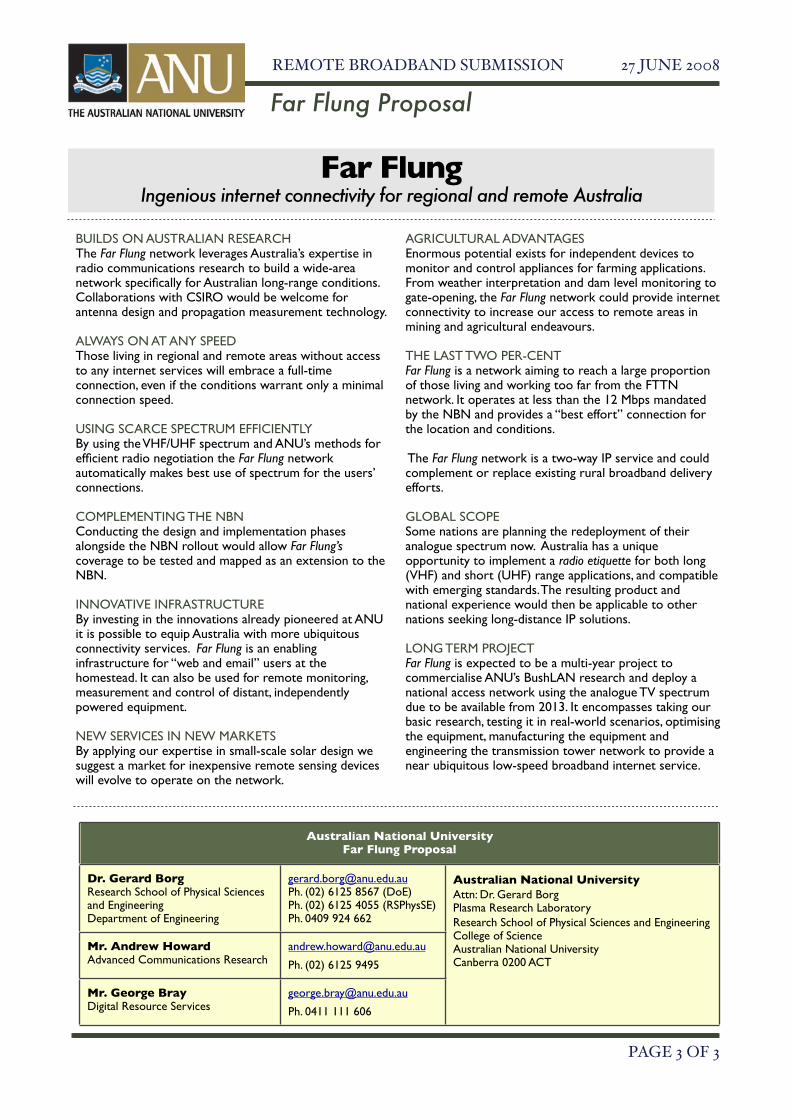
BUILDS ON AUSTRALIAN RESEARCHThe Far Flung network leverages Australia’s expertise in radio communications research to build a wide-area network specifically for Australian long-range conditions. Collaborations with CSIRO would be welcome for antenna design and propagation measurement technology.
ALWAYS ON AT ANY SPEEDThose living in regional and remote areas without access to any internet services will embrace a full-time connection, even if the conditions warrant only a minimal connection speed.
USING SCARCE SPECTRUM EFFICIENTLYBy using the VHF/UHF spectrum and ANU’s methods for efficient radio negotiation the Far Flung network automatically makes best use of spectrum for the users’ connections.
COMPLEMENTING THE NBNConducting the design and implementation phases alongside the NBN rollout would allow Far Flung’s coverage to be tested and mapped as an extension to the NBN.
INNOVATIVE INFRASTRUCTUREBy investing in the innovations already pioneered at ANU it is possible to equip Australia with more ubiquitous connectivity services. Far Flung is an enabling infrastructure for “web and email” users at the homestead. It can also be used for remote monitoring, measurement and control of distant, independently powered equipment.
NEW SERVICES IN NEW MARKETSBy applying our expertise in small-scale solar design we suggest a market for inexpensive remote sensing devices will evolve to operate on the network.
AGRICULTURAL ADVANTAGESEnormous potential exists for independent devices to monitor and control appliances for farming applications. From weather interpretation and dam level monitoring to gate-opening, the Far Flung network could provide internet connectivity to increase our access to remote areas in mining and agricultural endeavours.
THE LAST TWO PER-CENTFar Flung is a network aiming to reach a large proportion of those living and working too far from the FTTN network. It operates at less than the 12 Mbps mandated by the NBN and provides a “best effort” connection for the location and conditions.
The Far Flung network is a two-way IP service and could complement or replace existing rural broadband delivery efforts.
GLOBAL SCOPESome nations are planning the redeployment of their analogue spectrum now. Australia has a unique opportunity to implement a radio etiquette for both long (VHF) and short (UHF) range applications, and compatible with emerging standards. The resulting product and national experience would then be applicable to other nations seeking long-distance IP solutions.
LONG TERM PROJECTFar Flung is expected to be a multi-year project to commercialise ANU’s BushLAN research and deploy a national access network using the analogue TV spectrum due to be available from 2013. It encompasses taking our basic research, testing it in real-world scenarios, optimising the equipment, manufacturing the equipment and engineering the transmission tower network to provide a near ubiquitous low-speed broadband internet service.
Far Flung Proposal
Australian National UniversityFar Flung Proposal
Dr. Gerard BorgResearch School of Physical Sciences and EngineeringDepartment of Engineering
[email protected]. (02) 6125 8567 (DoE)Ph. (02) 6125 4055 (RSPhysSE)Ph. 0409 924 662
Australian National University Attn: Dr. Gerard Borg Plasma Research LaboratoryResearch School of Physical Sciences and Engineering College of ScienceAustralian National UniversityCanberra 0200 ACT
Mr. Andrew HowardAdvanced Communications Research
Ph. (02) 6125 9495
Mr. George BrayDigital Resource Services
Ph. 0411 111 606
Far FlungIngenious internet connectivity for regional and remote Australia

1
An Australia-wide Broadband Wireless Networkbased on TV Spectrum
Dr Gerard BorgDepartment of Engineering,
College of Engineering and Computer Science.Research School of Physical Sciences and Engineering,
College of Science.Australian National University
Canberra 0200 ACT.26 June 2008

2
Executive Summary
The provision of broadband services to regional and remote areas of Australia continuesto be a vexing national issue because of the repeated failure of existing technologies tomeet the challenge at a reasonable cost.
According to the ABS, 2.3 % of Australians live in remote areas. This class of thepopulation could number around 400,000 individuals who mostly dwell in isolated andblackspot areas. These citizens could benefit from on-line educational, health, bankingservices and e-commerce if only they had access to an Internet connection at 1 – 2 Mbps.
Unfortunately, there are misconceptions about the capabilities of wireless. So far only themost conventional technology alternatives such as satellite and microwave wirelessaccess have been canvassed. This problem is not confined to Australia and fewalternative solutions appear on the horizon.
In this report we propose an R&D effort to investigate and develop new technologiesthat exploit the TV bands: particularly the band I TV channels (45-70 MHz). Wepropose that a service of at least 1-2 Mbps can be provided to the 2.3% ofAustralian in remote areas. We also propose that better throughput can be obtainedby the judicious application of higher frequency TV spectrum (such as UHFspectrum) in some circumstances.
This solution would have the minimum cost of any technology and no doubt severalorders of magnitude lower than the cost of an Australia-wide Fibre to the nodenetwork.
This is a world first solution to the remote last mile problem. Early adoption will notonly provide a low cost and effective solution to the current service provisionproblem in regional and remote Australia, but will almost certainly become anexport opportunity.

3
1. The Problem
It remains clear that wireless networks hold the key to truly ubiquitous, low costbroadband services. Although speeds have been improving, the achievement of trulyubiquitous coverage has lagged. The main limiting factor has simply been the meaning ofcoverage. In cellular and WLAN networks coverage usually refers to the ability ofwireless signals to penetrate and propagate between buildings in built up areas. Such“non-line-of-sight” wireless links are popular because they obviate the need for externalroof mounted antennas for premises in close proximity to an access point (AP) or basestation (BS).
Coverage and non-line-of-sight propagation should also describe the ability of wirelesslinks to propagate around large terrain objects such as hills and mountains over terrainsspanning 3 – 100 kms. Investigations have been made of the use of wireless to servesparsely populated regional and remote areas. Lack of awareness of this work and acontinued worldwide R&D trend toward high throughput short-range wireless networkshas meant that future wireless technologies are unlikely to provide a connectivity solutionfor regional and remote areas. Evidence of this can be seen in the fact that world-wideroll-outs of wireless networks have been exclusively in the frequency range above 470MHz and more usually above 1 GHz. Wireless signals at these frequencies cannot beused to economically service regional and remote areas.
1.1 Why is it so difficult to access Remote Areas with Current Technologies?
Numerous wireless technologies are currently available in the market. All of theseoperate in the upper UHF range from 800 – 5000 MHz. In the context of providing longrange 20 – 50 kms in average Australian terrain, they all require a visual line-of-sightbetween the transmitter and receiver because their wavelengths are so short that the hillsand mountains completely shadow them.
The predicted range for a smooth earth is severely reduced if hills or mountains are in thepath.
This is not the case at the low VHF frequencies in TV band 1 (45 – 70 Mhz) as thesecan diffract over most of the hills and mountains that are typical of the Australianlandscape.

4
1.2 An Experimental Study of Diffraction and Coverage in TV Band I
To investigate low frequency coverage, an experiment was performed on channel 1 of theband I TV channels using an ACMA emission license. A 2.5 meter (half wavelength)dipole transmitting antenna at 59.5 Mhz was erected with vertical polarization on abuilding of height 20 meters (approx.) at the Australian National University (AustralianCapital Territory). A half-wave dipole antenna is omni-directional and has the lowestgain (2.15 dBi) of all antennas. The antenna was driven by a signal of 40 Watt CWpower. An identical receiving antenna was erected with a 20 meter height at theMolonglo Radio Telescope near Hoskinstown, Queanbeyan (New South Wales) andconnected to a receiver with baseband bandwidth 500 kHz. The telescope is situated atabout 32 kms from ANU. Figure 1 shows a map of the region.
Figure 1. Map of the ANU – Molonglo telescope propagationexperiment
A relief topography along an east-west line is also shown. Note that the link is not on avisual line-of-sight. In order for signal to arrive at the receiver, it must first diffract overan escarpment of relative altitude 200 m at a distance of about 5 kms from the receivingantenna.
The received signal had a measured signal to noise ratio (SNR) of 20 dB. Based on thetheoretical capacity that one can calculate for this SNR and 500 kHz of base bandbandwidth, one can draw the following equivalent conclusions.

5
(i) For an RF power of 40 Watts and a pair of dipoles each having a gain of2.15 dBi at each end of the link (as used in the experiment), the SNR andbaseband bandwidth of 500 kHz are sufficient for communications atabout 3 Mbps on this link.
(ii) A baseband bandwidth of 5 Mhz would support 30 Mbps for the samedipole antennas but would require a transmit power of 400 Watts tomaintain the same SNR.
(iii) A baseband bandwidth of 5 Mhz would support 30 Mbps for a transmitpower of 40 Watt if a pair of 7.15 dBi antennas were used in order tomaintain the same SNR.
Each of the above scenarios is achievable in practice and the approach one adopted woulddepend on the requirements of the service.
1.3 A Computational Study of Diffraction and Coverage as a Function of Frequency
Without an emission license for each frequency of operation, we could not repeat thisexperiment for frequencies higher than 59.5 MHz. We use a conventional path losscalculation model to compare the link budgets for a number of frequencies in which theescarpment is modeled by a smooth hill / diffracting object of height 200 m and width1500m located at 5 kms from the receiver. The ITU terrain model (ignoring antennagains) predicts a path loss that is slightly more pessimistic than the path loss for themodel of the 1500m radius, 200 m high diffracting object. The total range is 32 kms. Weassume that the transmitted power is 10 Watts (10 dBW) and that the antennas are halfwave dipoles. We assume that the noise at the receiver is determined by both thermal andan ambient or environmental component due to atmospheric effects.
The left three columns give the frequency, wavelength and baseband bandwidth (either 1MHz or 22 MHz, depending on the technology). The received signal to noise ratio (SNR)depends on the received signal strength which is mostly limited by receiver noise anddiffraction over the escarpment. The ambient noise figure is in dB above thermal noise.At 50 and 175 MHz, the noise is predominantly atmospheric and is much greater than athigher frequencies. Beyond 400 MHz the only noise is the thermal noise of the receiveritself, hence the frequency independence of noise power. The final column presents somerepresentative technologies that are currently used in these bands.
As can be seen, the negative SNRs point to a link severely shadowed by the escarpmentfor all frequencies except 50 MHz. Communications above 50 MHz is impossible onthis link.

6
FreqMHz
Wavel(m)
BasebandBW(MHz)
TX toescarpment(kms)
RX toescarpment(kms)
PathLossITUTerrainmodel
PathLossCircularobject ofradius1500m
AmbientNoiseFiguredB
TotalNoisePower300K(dBm)
SNR(dB)Circularobject ofradius1500m
Typ.Technol.
50 6 1 27 5 129.2 124.0 20 -94 10.3 AnalogTV
175 1.71 1 27 5 159.8 152.0 5 -109 -2.97 AnalogTV
403 0.74 1 27 5 189.0 176.3 0 -114 -22.4 FixedLinks
751 0.40 1 27 5 217.8 198.8 0 -114 -45.0 WRAN915 0.33 1 27 5 228.7 207.0 0 -114 -53.2 900 ISM
WLAN2300 0.13 1 27 5 293.4 254.0 0 -114 -100.2 WLAN2500 0.12 1 27 5 300.7 259.2 0 -114 -105.4 Slow
WiFi(1 MHz)
3500 0.086 1 27 5 333.0 281.7 0 -114 -127.9 WiMAX
2500 0.12 22 27 5 300.7 259.2 0 -100 -118.8 FastWiFi(22MHz)
5300 0.057 22 27 5 380.3 314.1 0 -100 -173.7 WiFi802.11a
We conclude that the choice of carrier frequency and not the technology is thefundamental limitation to long-range non-line-of-sight terrestrial wirelesscommunications. In order to significantly improve coverage in regional and remoteareas, one must choose frequencies in the spectrum of the band I TV channels (45 –70 MHz).
It should be stressed that this a relative result. Although coverage at UHF (above 500MHz) is much worse than at low VHF (45 – 70 MHz), this range is nonetheless muchbetter than at microwave frequencies (above 2.5 GHz). If deployed from a TV tower,UHF can have quite good coverage for some applications. For deployment fromantennas at ground level however, we are forced to use the low VHF spectrum in order toprovide data services suitable for remote and regional Australia.
It should also be stressed that the above scenario is a particularly adverse terrainexample among possible terrain scenarios. Nonetheless it is a typical situation inground level to ground level links.
In the next section we take a closer look at how to choose spectrum for differentapplications.

7
1.4 On the Suitability of Different Frequency Bands For Different Kinds of Services
The above calculations can be repeated for the case where the antenna at ANU is movedto black mountain tower (which is right near ANU) at an elevation of 150 m above theterrain and with a transmit power of 30 dBW (1 kWatt) and otherwise exactly the samelink conditions. At 50 MHz, we have a path loss of 121.5 dB and an SNR of 32.8 dB: a20 dB improvement achieved at greater financial and implementation cost. For 750 MHzwe have a path loss of 191.6 dB and SNR at the receiver of –17.8 dB. At 750 MHz, thelink is still shadowed. However if in addition, we use a pair of 15 dBi (high gain)antennas at each end of the link then we obtain 165.9 dB and 7.9 dB respectively. Thuseven for this difficult link it becomes possible to consider 750 MHz as an operatingfrequency. Since the wavelength at 750 MHz (0.40 m) is much lower than that at 50 MHz(6 m), it is not a difficult matter to manufacture high gain antennas for 750 MHz. Highgain antennas however have directional radiation patterns, whereas the antennas in thescenario of the above table are omni-directional.
Another important point to consider is that ranges of over a hundred kilometers at bothVHF and UHF can be obtained from towers, depending on the terrain. Thus site testing todetermine the best choice of operating frequency will be a feature of all TV band Internetservice installations.
We conclude that in some circumstances where terrain conditions are not tooadverse and towers are available, it is wise to consider the use of UHF frequencieswhere more spectrum is available to provide a better service. An obvious examplewould be the provision of data services to a community near a TV tower. One wouldservice the high population density of customers nearer to the tower using severalUHF channels with ample spectrum and adequate throughput and the lowerpopulation density of remote users on band I VHF channels.
1.5 How to Achieve Higher Data Rates than 1-2 Mbps
From the above discussion we can assume that with the SNR observed experimentally fora 500 kHz bandwidth, we obtain a theoretical maximum capacity of over 3 Mbps on thelink. Thus 1-2 Mbps should be achievable on average per 500 kHz of spectrumbandwidth in the band I VHF. Since there is 21 MHz of bandwidth in the three band I TVchannels we can say that 1 – 2 Mbps is available on 42 separate channels giving a total of42 – 84 Mbps. If more spectrum were made available at UHF in situations of high SNRone could consider using all of the 7 MHz channel bandwidth to provide higher data ratesin the range 14 – 28 Mbps. One could go further and even consider channel bonding,wherein adjacent TV channels are combined into larger spectrum blocks.
When SNR is high enough one can adapt the modulation scheme to use higher ordercoding. The 1 Mbps rate requires QPSK with 2 bits per symbol. 16-QAM, having 4 bitsper symbol, would produce 2 Mbps. 64-QAM, having 6 bits per symbol would produce 3Mbps. Frequency reuse using high gain antennas at high VHF and UHF also allows

8
improved overall throughputs. We discuss these and other methods further whenc o n s i d e r i n g a c a s e s t u d y .

9
2. Networking Solutions for Regional and Remote Areas
In this report we present an argument for the redeployment of band I TV spectrum for theprovision of telecommunications infrastructure and broadband services in regional andremote Australia. In the USA, the development of a TV band whitespace technologybased on cognitive radio is well advanced. This latest wireless technology is known asWireless Regional Area Networks (WRAN, IEEE 802.22). Cognitive radios are radiosthat are environmentally sensitive. They are capable of sensing and avoiding TVspectrum that is used for broadcast in local areas. Recently spectrum in the UHF TVbands around 700 MHz has been sold for the deployment of this technology, although thetechnology itself is still in the specification phase. It is important to note that there doesnot appear to be any plans to develop this technology for the band I TV channels as weare proposing here. In the USA, IEEE 802.22 only appears to be for deployments aboveabout 470 MHz.
In Australia, work on the characteristics and the suitability of the TV band I signals forbroadband applications in regional and remote areas has been the main goal of theBushLAN project at the Australian National University. The use of Band I TV spectrumas proposed here is unique. However the wireless coverage problems due to terrain areissues the world over. Australia has a unique window of opportunity to be the first todevelop the technology.
The first step is to obtain funding to properly scope out the research, development andapplication space for the use of TV spectrum for broadband wireless networks. The nextis to carry out the R&D. A summary of this R&D process is provided in section 3together with some important case studies that can be performed.
In the remainder of this section we describe four possible scenarios for the redeploymentof TV spectrum for wireless data networking.

10
2.1 A Regional Access Network
There are many regions of Australia that could be connected to broadband if a TV bandwireless service were installed on existing TV broadcast towers. Many of these towersare located in remote areas and contain much of the infrastructure already required. Thereare about 600 Broadcast Australia TV towers in Australia. This opportunity hasenormous potential to enhance Australia’s network infrastructure.
To make use of this resource, two things need to be done.
(i) A high speed backhaul network has to be provided in the form of a fibreoptic backbone to the TV broadcast towers.
(ii) A long range broadband wireless access network consisting of access points(APs) has to be installed on the towers. Subscribers gain access through acustomer premises equipment (CPE).
Figure 2 shows a pictorial representation of the RAN. It is a multiple access network, thatcould operate on several TV channels. Coverage would be enhanced by the elevation ofthe TV towers. Areas nearer to the tower and with the highest population density can beserviced by radios operating on UHF TV spectrum. The most remote and sparselypopulated areas would need to be serviced by the lower VHF frequencies. The towerantennas would have reasonable gain and would be sectorised to cover differentequatorial angles from the tower. Depending on the frequency of operation it should evenbe possible to reuse existing TV aerials at the customer premises.
11
Figure 2. The Regional Access Network.
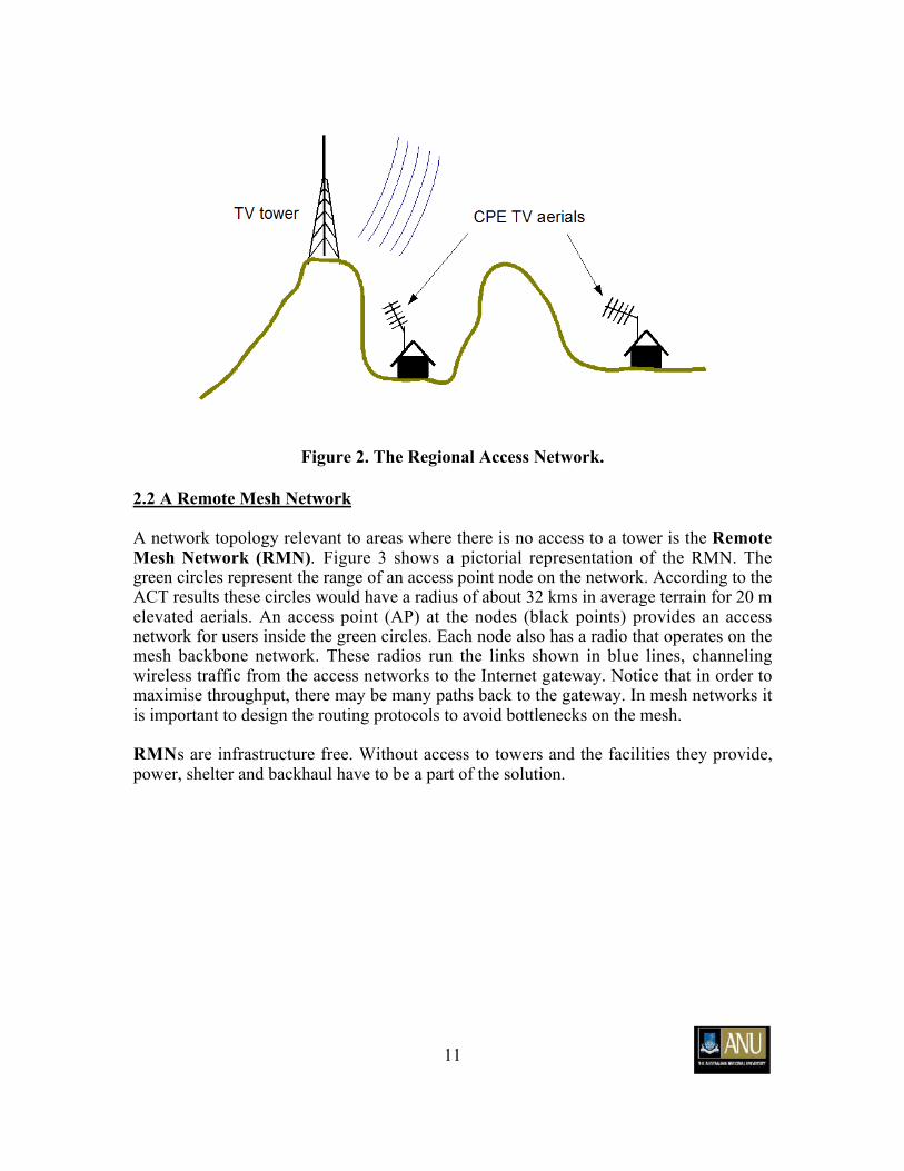
2.2 A Remote Mesh Network
A network topology relevant to areas where there is no access to a tower is the RemoteMesh Network (RMN). Figure 3 shows a pictorial representation of the RMN. Thegreen circles represent the range of an access point node on the network. According to theACT results these circles would have a radius of about 32 kms in average terrain for 20 melevated aerials. An access point (AP) at the nodes (black points) provides an accessnetwork for users inside the green circles. Each node also has a radio that operates on themesh backbone network. These radios run the links shown in blue lines, channelingwireless traffic from the access networks to the Internet gateway. Notice that in order tomaximise throughput, there may be many paths back to the gateway. In mesh networks itis important to design the routing protocols to avoid bottlenecks on the mesh.
RMNs are infrastructure free. Without access to towers and the facilities they provide,power, shelter and backhaul have to be a part of the solution.

12
Figure 3. The Remote Mesh Network.

13
2.3 Other VHF Network Applications
Access to low frequency VHF spectrum, whether supplied from TV towers as in the caseof the RAN or in a mesh networking fashion as in the case of the RMN, is not confined toInternet services. Telemetry and other communications infrastructure projects that rely onlong range communications now become possible.
2.3.1 A Remote Telemetry Network
There are many situations in the mining industry and in scientific research where lowbandwidth sensor networks relay information over long distances. Such a network issimilar to an RMN. A scattered array of access networks feed data to aggregating nodesthat relay the data to a backbone. Such networks would have greater coverage and lowercost than the short range mobile phone networks currently in use.
2.3.2 Coastal Broadband Network
Ocean swell and earth curvature prevent the use of microwave frequencies for coastalcommunications. Access to low frequency VHF spectrum could provide long rangenetworking solutions for coastal surveillance purposes and the extension of telephone andbroadband networks to off-shore locations, such as coastal islands, oil rigs and ships. Asa concrete example consider a wireless relay network across Bass Strait in which a longrange VHF network provides broadband services to oil rigs and vessels for scientificpurposes.

14
3. Operational Plan
In this section we describe in broad terms the steps required to bring a national TV bandwireless network to fruition. We discuss the various research and development stages.We also propose case studies of the solutions presented in section 2.
There will be four stages in the development of the VHF wireless system for each of theproposed networking solutions.
1) Wireless channel research and case studies.2) Design review of the underlying wireless technology.3) The implementation of a working concept demonstrator base and CPE modem (RAN)
and a wireless mesh network (RMN).4) Network trials.
3.1 Regional Access Network
The regional access network benefits from the existing network of TV broadcast towers.The aim of this TV band wireless network is to capitalise on this existing infrastructure toimprove communications services.
3.1.1 Wireless channel and signal research
The regional access network (RAN) will require access to a TV tower with a nominalheight of 150 meters (for example Black Mountain Tower). We envisage four phases ofresearch:
1) Coverage and channel response,2) Atmospheric and impulse noise investigations, signal quality and data throughput,3) Telephony and video conferencing tests,4) Case studies.
15
Phase 1. Coverage and channel response. The first set of trials will investigatecoverage performance and channel dynamics. Because the towers are elevated over thesurrounding terrain the signal range with 7 MHz bandwidth could be over 100 kms evenat UHF. Therefore there is the possibility of investigating and developing systems tooperate over the whole TV band from 45 – 820 MHz. The trials will be performed around50, 175 and 750 MHz to cover the range of available frequencies for the low VHF bandand a typical UHF frequency relevant to 802.22.
In many circumstances it would be advantageous to exploit spectrum at higherfrequencies, in order to maximise available bandwidth to subscribers nearer to thetowers. The VHF spectrum would be reserved for the long range subscribers. Dependingon spectrum availability, it may be necessary to operate the long range links at the highestfrequency possible where spectrum is available.
These trials will be used to assess coverage and verify terrain field mapping software thatwill become a necessary tool for future network design.
Phase 2. Atmospheric and impulse noise investigations, signal quality and datathroughput. Site surveys of interference and noise will reveal the existence of TV bandcommunications system impairments. Impulse and power line noise are especiallysignificant at low frequencies and have been known to deleteriously affect DTVreception. It addition there will be co-channel interference from TV emissions (especiallyinter-state vision carriers). We also have to learn how to design networks free of co-channel interference. We know that anomalous propagation such as troposcatter andspace wave at low VHF could be present. Troposcatter may even be exploited for verylong range communications (1000 kms).
Previous experiments have been performed using channel sounding techniques toinvestigate the effects of multi-path (channel induced echoes) which leads to inter-symbol interference (ISI). We do not anticipate significant ISI at 50 MHz but ISI couldbe worse at UHF frequencies. ISI will be handled by standard signal processingtechniques such as equalisation and (if useful) OFDM1.
Raw base band signals will be recorded using instrumentation transceivers for off-lineanalysis. They can be used for receiver design and simulations to predict networkthroughputs.
Phase 3. Telephony and video conferencing tests. Future IP networks will need tosupply voice and video. Optimisation of the network to provide a high quality service canbe performed using the phase 2 data. Experimental tests can also be performed using off-the-shelf equipment.
1 Orthogonal Frequency Division Multiplexing: a data multiplexing technique used in nearly all modernwireless standards.

16
Phase 4. Case studies. We will perform case studies of such a system to predict systemperformance.
3.1.2 Design Review.
A design review of wireless hardware and software will follow. This should be a rapidprocess as much work has already been done. The aim is to write the detailedspecification for the RAN.
Information on coverage and channel impairments will directly influence the design ofthe antenna (the required antenna gain will affect the size of the antenna with the largestantennas being at the lowest frequencies) and the power amplifier (certain modulationschemes need linear class A or AB amplifiers). The physical layer processing will bedirectly influenced by impulse noise and cochannel interference.
Power line and impulse noise and co-channel interference from inter-state TV visioncarriers has generally been a problem in experiments performed in the ACT. Theseeffects are not so severe at UHF frequencies. Thus even at 50 MHz with 10 Watts ofpower, a sophisticated receiver will still be required for communications.
Conversely we will have to assess possible interference produced on existing broadcastservices. In the USA the 802.22 radios are planned to be cognitive radios capable ofsensing broadcast signals and setting their carriers to avoid interference. We will need todecide whether BushLAN has to be cognitive.
The RAN requires a MAC protocol to control access among many users. We haveanalysed a couple of MAC protocols in BushLAN that may be applicable. Because thesame technology will be operational at both ends of a link some form of in-linecompression may be used for uncompressed web traffic in order to enhance throughput.
3.1.3 Development of Concept Demonstrators
Following the design review, the next step is to build concept demonstrators satisfyingthe requirements. Some properties of these demonstrators are already clear but needfurther investigation.
The tower base station or access point (AP)
〈 Capable of instantaneous tuning over the TV band,〈 The addition of Software Defined Radio capability for future proofing. For example,
if the 802.22 standard is made mandatory in future years then the existing BushLANradios can be reprogrammed to suit.
〈 Present 802.22 specs appear to suggest OFDM (Orthogonal Frequency DivisionMultiplexing) in the PHY layer. If we adopt this scheme then all power amplifierswill have to be class A linear (expensive). In addition, with OFDM, impulse noise
17
may be a problem. Thus whether we follow the 802.22 specification here is not yetclear.
〈 The antenna will allow a degree of sectorised pattern shaping.〈 If there is a need for full duplex operation at the base then a filter diplexer must be
implemented. This is an expensive and difficult option to implement for closelyspaced frequency channels.
The consumer premises equipment (CPE)
〈 Must operate at lower power than the AP.〈 Will support less bandwidth for the same range as the AP. This is convenient because
a number of CPEs will be sharing the downlink with uplink-downlink load matching.
The CPE must also operate at low power if commercial grade TV aerials are to be used.In this case the CPE and a TV set could share the same aerial. UHF RF power is lesslikely to heat the aerial baluns than VHF RF power. This matter will need investigation.
3.1.4 Network Trials
This is the final phase of development in which the radio concept demonstrators aretested in the field.

18
3.2 Remote Mesh Network
The procedure for the development of the remote mesh network (RMN) will be similarto that for the RAN. The RMN is a user access network in which traffic is transportedfrom one network node to another toward an aggregation point where high speedbackhaul to the Internet is provided. User access to the mesh would be similar to that inthe RAN. Since there is no shelter, power or backhaul, the environmental conditions andnetwork requirements are tougher.
The RMN wireless coverage and signal experiments will be performed in terrain that ismore intractable than the norm. These experiments must be less restrictive than thosereported so far in the ACT. The main difference compared to the RAN is that antennaswill not be elevated. Elevations as low as 5 meters (house roof height) to 25 meters(building roof height) will pose a major challenge to long range communications.Coverage experiments and validation of terrain mapping software will allow us to planfuture networks. The mesh network will most often operate at low frequency VHF.
The other development phases and their issues are similar to those of the RAN. The poorcoverage of non-elevated aerials driven at UHF compared to the coverage at 50 MHz(low VHF) implies a lower access to spectrum and hence much lower bounds onattainable throughput. On short-range links in the access networks, bandwidth might beenhanced if transmission is possible at UHF or microwave frequencies. In a case studybelow we show that this may even be the case in the indigenous communities of theremote Northern Territory.

19
3.3 Case Study: A Remote Mesh Network for the Northern Territory.
Figure 4 shows one embodiment of an RMN. Each access network region (azure dashedcircle) is serviced by an AP. There are three circles each exploiting two adjacent 1.167MHz channels in a 7 MHz TV channel. The AP radiation patterns are circular. The red,blue and brown ellipses depict the radiation patterns of the VHF mesh links that form thenetwork backbone. In this example the mesh has a string of pearls topology, howeverother topologies such as that in figure 3 will sometimes be more appropriate and efficient.In this example, the mesh links operate on the same spectrum as the APs. This is onlynecessary if only one VHF TV channel is available and the access network is also a longrange network using antennas of low elevation. Notice how the frequencies are chosen sothat the same frequency is not reused in the same location. The radiation patterns of themesh antennas have twice the gain in order to support twice the bandwidth for the samerange.
The reuse of frequencies can be maximised if the radii of the access network regions issufficiently small. In this case UHF TV bands involving multiple bonded 7 MHzchannels could lead to much higher network efficiencies provided that sufficient VHFspectrum is dedicated to the mesh links.
Figure 4. An RMN topology using one 7 MHz Band I TV band
Let us consider a difficult case in which Internet services are currently very poor. We willuse the 7 MHz spectrum block of Band I TV Ch 0 to serve the indigenous communitiessurrounding Alice Springs in the Northern Territory (Figure 5). For an RMN withouttowers we can expect about 32 kms for antennas on 20 meter masts at each end of a link.Given similar terrain conditions to that in the ACT experiment described above, we canexpect there to be few black spots at carrier frequencies in the range 45 - 52 MHz and RFpowers ~100 Watts (20 dBW). We may therefore assume the range contours to becircular.

20
The indigenous colonies are shown in the map of Figure 5 below with the populations of500 – 3000 (green), 50-500 (blue), 20-50 (red), 10-20 (yellow) and 0-10 (mauve): a totalpopulation upper limit of about 46,800 individuals. Each circle in the figure has a radiusof 32 kms. An access point (AP) located at the centre of each circle is equipped with anomni directional antenna (similar to the above ACT experimental measurements) andserves the access network. Backhaul can be supplied either by satellite if necessary (worstcase and most expensive option) or by mesh networking between circles (no ongoingcosts) as described above. In the case of the mesh network, the mesh is assumed toterminate at an Internet gateway with a broadband backbone. For clarity the VHF meshlinks are not shown in the figure.
A data rate of 2.33 Mbps is available per 1.167 Mhz RF spectrum bandwidth based onerror free transmission using QPSK. Since there will be two such channels per circle inthe above network model, we can supply 4.67 Mbps to the communities within a circle.
As one can see from the figure, a population of up to 46,800 could be serviced by 47nodes in a mesh network covering an area of about 1000kms x 1000kms. The above datarate could be further increased by a number of techniques. If SNR is sufficiently high, ahigher level modulation scheme such as 16-QAM would give 9.33 Mbps or 64-QAM, 14Mbps. In-line compression would increase throughput by perhaps a factor of ten foruncompressed web traffic (as opposed to compressed voice, video and downloads whichwould be unaffected). Greater data rates can easily be achieved by sectorisation of beampatterns to allow frequency reuse within each access region (azure blue circles).

21
Figure 5 Map of the southern Northern Territory and northern South Australia.Coloured spots show the population centers. The azure blue circles show the range
of the access networks of the RMN.
22
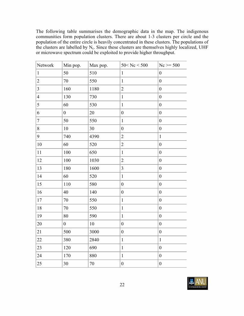
The following table summarises the demographic data in the map. The indigenouscommunities form population clusters. There are about 1-3 clusters per circle and thepopulation of the entire circle is heavily concentrated in these clusters. The populations ofthe clusters are labelled by Nc. Since these clusters are themselves highly localized, UHFor microwave spectrum could be exploited to provide higher throughput.
Network Min pop. Max pop. 50< Nc < 500 Nc >= 500
1 50 510 1 0
2 70 550 1 0
3 160 1180 2 0
4 130 730 1 0
5 60 530 1 0
6 0 20 0 0
7 50 550 1 0
8 10 30 0 0
9 740 4390 2 1
10 60 520 2 0
11 100 650 1 0
12 100 1030 2 0
13 180 1600 3 0
14 60 520 1 0
15 110 580 0 0
16 40 140 0 0
17 70 550 1 0
18 70 550 1 0
19 80 590 1 0
20 0 10 0 0
21 500 3000 0 0
22 380 2840 1 1
23 120 690 1 0
24 170 880 1 0
25 30 70 0 0

23
Network Min pop. Max pop. 50< Nc < 500 Nc >= 500
26 210 1300 2 0
27 110 600 1 0
28 80 590 1 0
29 70 550 1 0
30 600 3640 1 1
31 70 560 1 0
32 60 160 0 0
33 150 1120 2 0
34 110 1010 2 0
35 30 70 0 0
36 20 60 0 0
37 20 40 0 0
38 70 550 1 0
39 170 1550 3 0
40 150 1120 2 0
41 460 3390 6 0
43 50 500 1 0
44 520 3050 0 1
45 50 130 0 0
46 120 1040 2 0
47 520 3050 0 1

24
3.4 Remote Telemetry Network
The RTN investigation program is similar to that of the RMN. Telemetry is a verycommon application of low bandwidth wireless. Often however range is a problem.Consider the following figure which shows the locations of soil moisture, temperatureand rainfall measurement equipment in the Goulburn River catchment near Newcastle(NSW). This information is gathered as a part of the SASMAS project2.
Figure 6. The SASMAS project in the Hunter Valley NSW. The red spots show thelocations of hydrology diagnostic stations. Currently these are serviced in most cases
by GSM modems but the five most southern diagnostic stations are inaccessible.
In this telemetric application data has to be retrieved from some fairly isolated locationstypically separated from each other by about 40 kms. The mesh network conceptpresented above could be applied here and to many similar telemetric applications to pipelow bandwidth data from site to site back to an aggregation point.
2(http://www.eng.newcastle.edu.au/sasmas/SASMAS/sasmas.htm)
25
4. Research Funding
The experimental results and techniques presented above are a part of the researchoutcomes of the BushLAN project at the Australian National University. This researchwas partially funded by the following government grants.
1) ARC grant LP0349390. VHF wireless technologies for last-mile Internet access inregional Australia. Dr Gerard Borg, Prof Jeffrey Harris, Dr Haley Jones, The AustralianNational University 2003.
This grant provided funding for radiofrequency measurement equipment, thedevelopment of digital radio components and radiofrequency hardware and electronicconstruction services.
2) ARC grant LP0347407. Infrastructure for wireless Internet technology developmentfor rural Australia. Dr Gerard Borg, Prof Jeffrey Harris, Dr Haley Jones, Prof AndrewCheetham, Adj/Prof John Raynor. The Australian National University. 2003.
This grant provided funding for a post-graduate stipend and technical assistance.
3) ARC Government grant “ACT Knowledge Fund”. Tony Cooke, Jeffrey Harris andGerard Borg (2003).
This grant provided funding for electronic hardware and equipment used in the research.


![29 Pieces - Collection of easy pieces [(1st and 2nd grade)]...3 4 Ï Ï Ï Ï Ï Ï Ï Ï Ï Ï Ï Ï Ï Ï Ï Ï Ï Ï Ï Ï Ï Ï Ï Ï Ï HH. . H. HH. . 3. 3 F 4 4 2 1 & Ï Ï Ï](https://static.fdocuments.net/doc/165x107/607dfb30bfd4bb18cf1b3abb/29-pieces-collection-of-easy-pieces-1st-and-2nd-grade-3-4-.jpg)