
Broadband Dual-Modes Slot Spiral Antenna Design...
18
行政院國家科學委員會專題研究計畫 期中進度報告 封裝系統(SOP) 內部微縮化被動元件的分析與設計(1/3) 計畫類別: 個別型計畫 計畫編號: NSC92-2213-E-002-070- 執行期間: 92 年 08 月 01 日至 93 年 07 月 31 日 執行單位: 國立臺灣大學電信工程學研究所 計畫主持人: 江簡富 報告類型: 精簡報告 報告附件: 出席國際會議研究心得報告及發表論文 處理方式: 本計畫可公開查詢 中 華 民 國 93 年 5 月 25 日
Transcript of Broadband Dual-Modes Slot Spiral Antenna Design...
行政院國家科學委員會專題研究計畫 期中進度報告
封裝系統(SOP)內部微縮化被動元件的分析與設計(1/3)
計畫類別:個別型計畫
計畫編號:NSC92-2213-E-002-070-
執行期間:92年08月01日至93年07月31日
執行單位:國立臺灣大學電信工程學研究所
計畫主持人:江簡富
報告類型:精簡報告
報告附件:出席國際會議研究心得報告及發表論文
處理方式:本計畫可公開查詢
中 華 民 國 93年5月25日
Broadband Slot Spiral Antenna with External Feed and Microstrip-to-Slotline Transition
Wen-Zhou Wu*, Tze-Hsuan Chang, and Jean-Fu Kiang
Department of Electrical Engineering and Graduate Institute of Communication Engineering National Taiwan University, Taipei, Taiwan, ROC
E-mail: [email protected] 92-2213-E-002-070
I. Introduction
As the demand for spread spectrum and multifunction RF systems increases, antennas that are capable of wideband/multiband operation are becoming more and more desirable in recent years. Spiral antennas with inherent broadband nature meet the requirements for automotive applications [1]. Recently, slot spiral antennas with or without reflecting cavity have been widely studied [2]-[5]. In this work, we propose a new design of slot spiral antenna with external feed combined with wideband microstrip-to-slotline transition and backed with a reflecting cavity for unidirectional radiation and gain enhancement. A new approach to identify the active region of spiral antenna will also be presented. II. Antenna Design
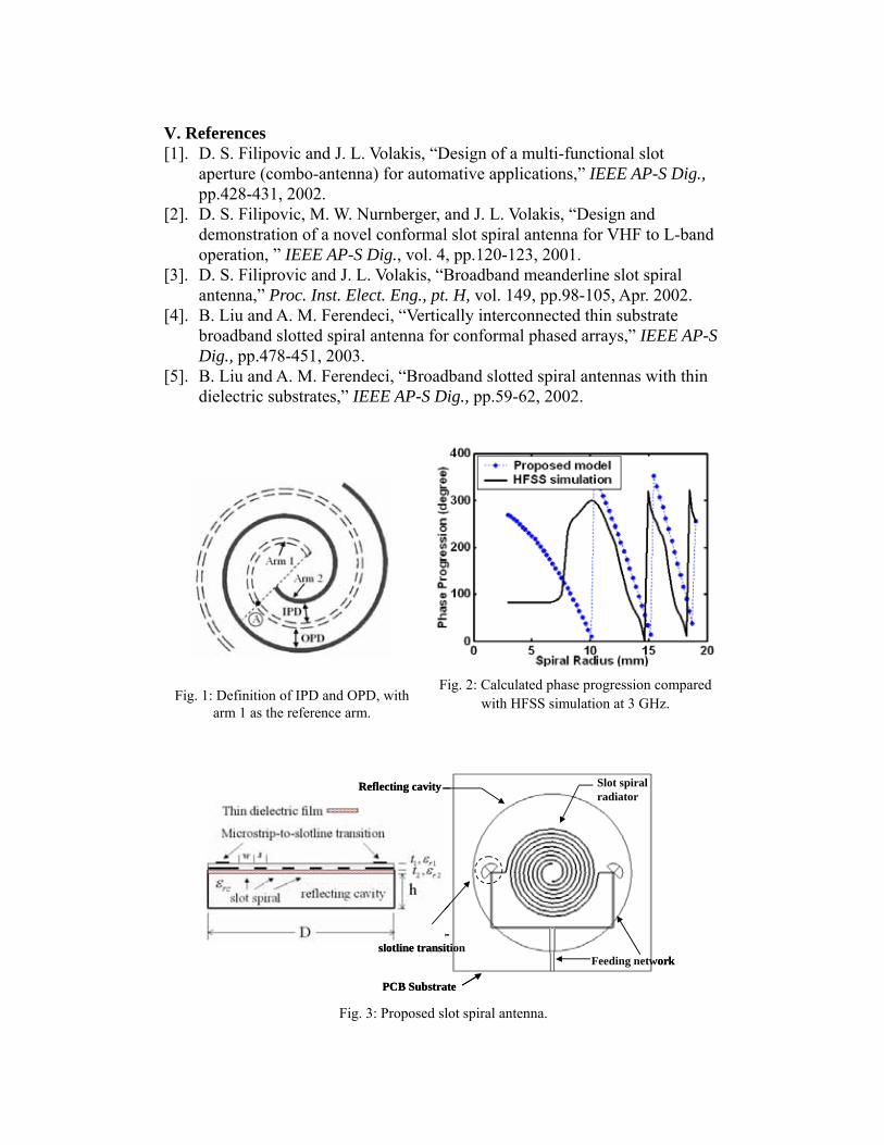
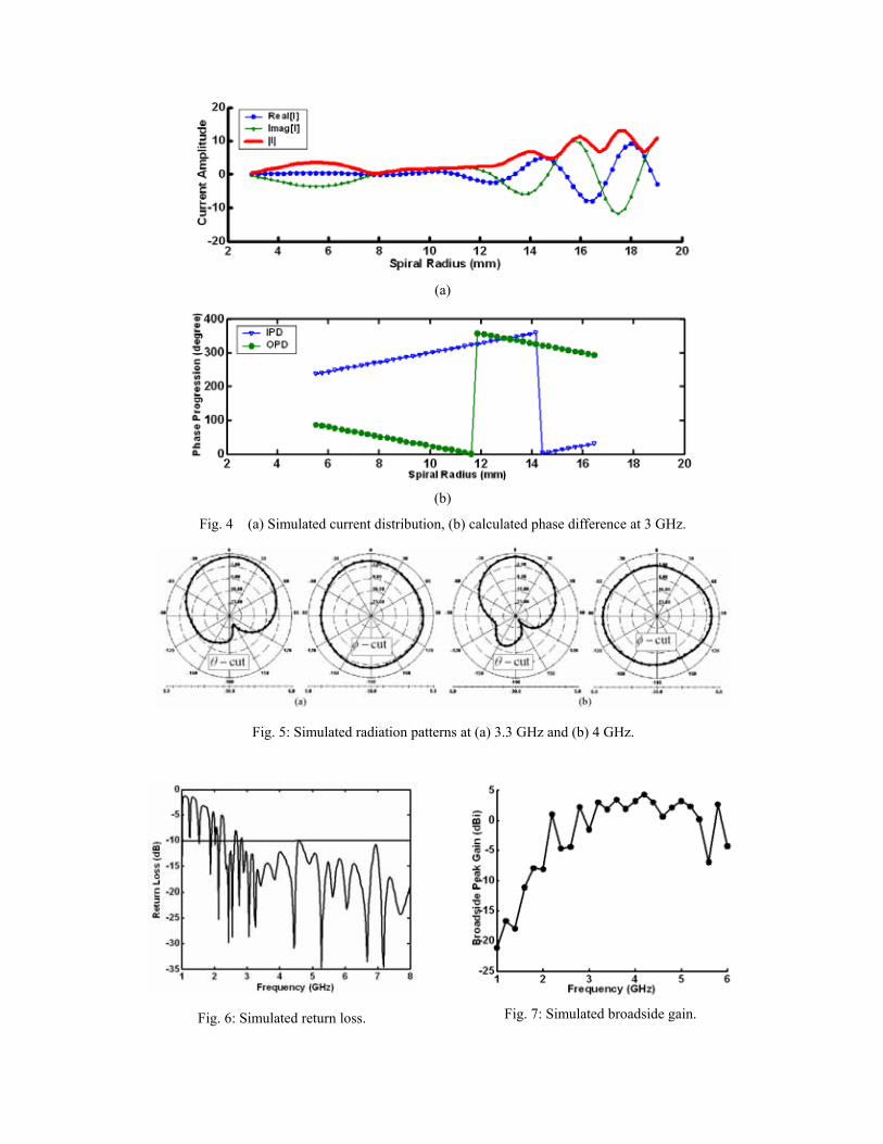
The Archimedean spiral can be expressed as 0r r aφ= + , where is the growing rate and 0 is the initial radius. The concept of active region states that the far-field radiation is mainly contributed from the region of about one-wavelength circumference and balanced feed is required for mode 1 operation. The current and phase distributions are the figure of merits to identify the traveling wave characteristics of spiral antennas. In this work, we propose a new approach to identify the active region. First define two arm-to-arm phase differences, labeled as inner phase difference (IPD) and outer phase difference (OPD) with respect to the reference arm as shown in Fig.1. The phase distribution along the spiral arm is obtained by considering the slotline dispersive characteristics and spiral geometry. This approach is verified by full-wave simulation using HFSS, as shown in Fig.2. The simulated results show that constant phase occurs due to standing wave near the end of spiral arm. The difference between the calculated and simulated phase are significant but the trend is consistent and can be improved by employing more accurate slotline dispersive models. Fig.4 shows the simulated current distributions. Fig.4(b) shows that the active region is roughly located between the two points with zero phase difference associated with IPD and OPD, respectively. The predicted active region is very close to that predicted by using current band theory. Notice that the active region is accompanied by decaying current amplitude. Since our approach is more straightforward, it will used throughout
ar
this work. Fig.3 shows the proposed slot spiral antenna with external feed by
incorporating the wideband microstrip-to-slotline transition and backed with a reflecting cavity. The spiral growing rate is 0.8117 mm/rad, slot width is 0.3 mm and spiral turns is 3.2. The spiral radius Rmax and Rmin is approximately 18 and 2 mm for mode 1 operation over 2 to 6 GHz. The arm-to-arm spacing is 7.5 times of slot width to reduce the arm-to-arm coupling. An additional thin-film dielectric can be added between the spiral substrate and reflecting cavity in order to miniature the antenna size. The radius of reflecting cavity is 35mm and its depth is 10 mm. The feeding network is consisted of microstrip power divider, impedance taper line and two wideband microstrip-to-slotline transition with radial stubs. A Klopfenstein taper is designed as impedance transformer.
The radius of radial stubs is approximately 6gλ of the microstrip and slotline. The size of antenna is 90×90 mm
2 and is built on an FR4 substrate
with 4.4rε = , and . tanδ=0.022 h=1.6mm III. Simulation Results and Discussion
Fig. 6 shows the simulated return loss of proposed slot spiral antennas. The bandwidth of 10 dB return loss covers 2.2 to 8 GHz due to the traveling wave characteristics with decaying current distribution as shown in Fig.4(a). The phase progression, as shown in Fig.2, also shows the traveling wave characteristics with insignificant standing wave near the end of spiral arm at 3 GHz. The real and imaginary part of currents also maintains a 90
o phase
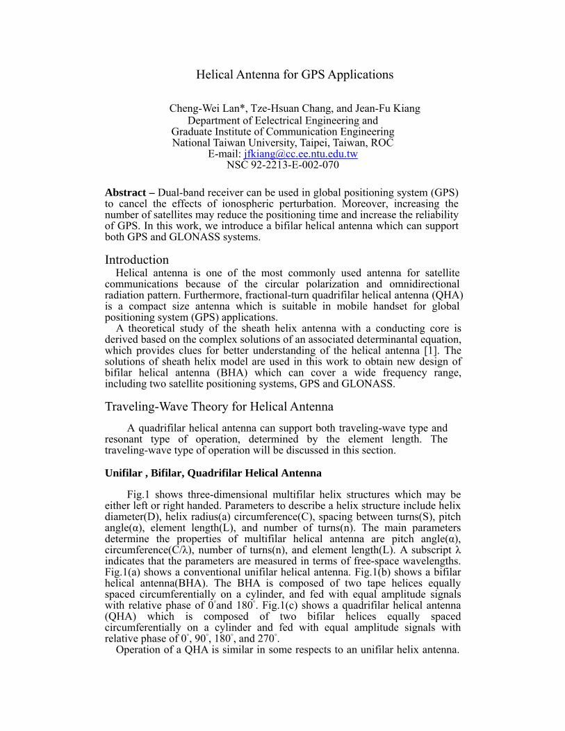
difference. Fig.5 shows the LHCP radiation patterns at 3.3 and 4GHz, respectively. Notice that the radiation patterns are similar with broaden beams at lower operating frequencies. The radiation patterns at higher frequencies are degraded due to the standing wave near the end of spiral arm. The radiation patterns are close to omnidirectional in the horizontal plane. Fig.7 shows the simulated broadside gain. Approximately 3 dBi is obtained over 3 to 5 GH. The gain degradation at low frequencies are mainly due to the poor input matching and the gain degradation at higher frequencies are mainly due to the standing wave near the end of spiral arm. EM absorber materials can be placed within the cavity to reduce reflection. In addition, spiral antennas with dual-mode operation for satellite and terrestrial applications attract more and more attenuations. Another novel design of broadband 180
o hybrid feeding network
used for dual modes operation is under development. Acknowledgment: This work is sponsored by the National Science Council, ROC, under contract NSC 92-2213-E-002-070. IV. Conclusions
A new design of broadband slot spiral antenna is proposed. The simulated results show that return loss bandwidth covers from 2.2 to 8 GHz. The gain performance is approximately 3 dBi over 3 to 5 GHz. A new active region identification approach is also proposed and verified with HFSS simulation, which can be used to identify the size reduction ratio of meandered spiral.
V. References [1]. D. S. Filipovic and J. L. Volakis, “Design of a multi-functional slot
aperture (combo-antenna) for automative applications,” IEEE AP-S Dig., pp.428-431, 2002.
[2]. D. S. Filipovic, M. W. Nurnberger, and J. L. Volakis, “Design and demonstration of a novel conformal slot spiral antenna for VHF to L-band operation, ” IEEE AP-S Dig., vol. 4, pp.120-123, 2001.
[3]. D. S. Filiprovic and J. L. Volakis, “Broadband meanderline slot spiral antenna,” Proc. Inst. Elect. Eng., pt. H, vol. 149, pp.98-105, Apr. 2002.
[4]. B. Liu and A. M. Ferendeci, “Vertically interconnected thin substrate broadband slotted spiral antenna for conformal phased arrays,” IEEE AP-S Dig., pp.478-451, 2003.
[5]. B. Liu and A. M. Ferendeci, “Broadband slotted spiral antennas with thin dielectric substrates,” IEEE AP-S Dig., pp.59-62, 2002.
Fig. 2: Calculated phase progression compared with HFSS simulation at 3 GHz.
Fig. 1: Definition of IPD and OPD, with arm 1 as the reference arm.
Reflecting cavity
PCB Substrate
Slot spiralradiator
Feeding network
Microstrip-to-slotline transition
Reflecting cavity
PCB Substrate
Slot spiralradiator
Feeding network
Microstrip-to-slotline transition
Fig. 3: Proposed slot spiral antenna.
(a)
(b)
Fig. 4 (a) Simulated current distribution, (b) calculated phase difference at 3 GHz.
Fig. 5: Simulated radiation patterns at (a) 3.3 GHz and (b) 4 GHz.
Fig. 7: Simulated broadside gain. Fig. 6: Simulated return loss.
Helical Antenna for GPS Applications
Cheng-Wei Lan*, Tze-Hsuan Chang, and Jean-Fu Kiang Department of Eelectrical Engineering and
Graduate Institute of Communication Engineering National Taiwan University, Taipei, Taiwan, ROC
E-mail: [email protected] 92-2213-E-002-070
Abstract – Dual-band receiver can be used in global positioning system (GPS) to cancel the effects of ionospheric perturbation. Moreover, increasing the number of satellites may reduce the positioning time and increase the reliability of GPS. In this work, we introduce a bifilar helical antenna which can support both GPS and GLONASS systems.
Introduction Helical antenna is one of the most commonly used antenna for satellite communications because of the circular polarization and omnidirectional radiation pattern. Furthermore, fractional-turn quadrifilar helical antenna (QHA) is a compact size antenna which is suitable in mobile handset for global positioning system (GPS) applications.
A theoretical study of the sheath helix antenna with a conducting core is derived based on the complex solutions of an associated determinantal equation, which provides clues for better understanding of the helical antenna [1]. The solutions of sheath helix model are used in this work to obtain new design of bifilar helical antenna (BHA) which can cover a wide frequency range, including two satellite positioning systems, GPS and GLONASS.
Traveling-Wave Theory for Helical Antenna A quadrifilar helical antenna can support both traveling-wave type and
resonant type of operation, determined by the element length. The traveling-wave type of operation will be discussed in this section.
Unifilar , Bifilar, Quadrifilar Helical Antenna
Fig.1 shows three-dimensional multifilar helix structures which may be either left or right handed. Parameters to describe a helix structure include helix diameter(D), helix radius(a) circumference(C), spacing between turns(S), pitch angle(α), element length(L), and number of turns(n). The main parameters determine the properties of multifilar helical antenna are pitch angle(α), circumference(C/λ), number of turns(n), and element length(L). A subscript λ indicates that the parameters are measured in terms of free-space wavelengths. Fig.1(a) shows a conventional unifilar helical antenna. Fig.1(b) shows a bifilar helical antenna(BHA). The BHA is composed of two tape helices equally spaced circumferentially on a cylinder, and fed with equal amplitude signals with relative phase of 0°and 180°. Fig.1(c) shows a quadrifilar helical antenna (QHA) which is composed of two bifilar helices equally spaced circumferentially on a cylinder and fed with equal amplitude signals with relative phase of 0°, 90°, 180°, and 270°.
Operation of a QHA is similar in some respects to an unifilar helix antenna.

The determinantal equation of N-filar tape helix, excited in the exp(-jψ) mode, becomes identical to the sheath helix as the number, N, approaches infinity [2]. Assume that the BHA has the same characteristics with the QHA. Thus, we can estimate the properties of traveling-wave type QHA and BHA by the theory of unifilar helix.
k-β Diagram of Helix Structure
Periodic structure approach can be applied to analyze the helix of infinite extent by the mode diagram shown in Fig.2. Three modes of operation are marked as modes a, b and c, representing the normal, scanning(back-fire), and axial modes, respectively.
In curve a, the cylindrical harmonic of m=0 dominates. The axial mode is dominated by the right-handed cylindrical harmonic of m=1, also referred to as the m=1 supermode.
Sheath Helix Model
Fig.3(a) shows an infinitely long tape helix. Fig.3(b) shows the associated sheath helix model [1]. The helix is modeled as a sheath with different conductivities in different directions. The sheath helix model for an infinitely long helix is mathematically simple but physically inaccurate. Taking the limit that the inner radius, b, approaches the outer radius, a, we obtain the following four uncoupled solutions where m indicates the spatial harmonic. The axial propagation constant, β, can be calculated by solving for the roots of the determinantal equation. The k-β diagram of sheath helix is generated by solving β with free-space wave number (frequency) . The four uncoupled solutions can be used to predict the operation of a helical antenna.
β= ± k (1) βa tanα= ±ka/cos(α)-m, m=0, ±1….. (2)
Fig.4 shows the k-β diagram of sheath helix model. At low frequency, the dispersion curve lies within the bound-wave region, the total field is completely bound to the structure and all spatial harmonics are axially slow. When frequency is increased, the m=1 harmonic enters the fast-wave region at A1. At this frequency, only one point is located in the fast-wave region, which exhibits a single beam at the back-fire direction in the visible region.
With the frequency increased, the m=1 beam scans through the broadside at B1. Subsequently, the beam resulting from m=1 harmonic continues to sweep toward the end-fire at E1, and then the m=1 harmonic leaves the fast-wave region. In the fast-wave region, the wave is a leaky wave. For frequency above E1, the m=1 harmonic becomes a slow wave and the beam moves into the invisible region.
The m=2 harmonic has the same characteristics. For large pitch angle, there are two dispersion curves, m=1 and m=2, at a given frequency. We should avoid such circumstance when designing helical antenna.
For unifilar helical antenna, the maximum pitch angle is approximately 20°. Reference [8] shows the relation between pitch angle and the number of helices. The optimal pitch angle of BHA is approximately two times that of unifilar HA.
The four uncoupled solutions can also used to obtain the bandwidth of helical antenna and the limit of pitch angle. This result is in good agreement with the experiment results of J. D. Kraus [5].

Antenna Design For GPS application, a dual-band receiver can cancel the effects of
ionospheric perturbation. Moreover, increasing the number of satellites can reduce the positioning time and increase the reliability of the GPS. Currently, there are two major positioning systems, GPS and GLONASS. Various manufacturers of GPS equipments use different size and construction to cover either of the two GPS frequencies at 1575.42MHz(L1) and 1227.6MHz(L2). In this work, we design a BHA to cover the four frequencies of GPS and GLONASS.
Requirements on GPS Antenna
For GPS applications, the antenna requires omnidirectional pattern over approximately the entire upper hemisphere where the satellites may be visible with right-handed circular polarization. The wide beamwidth coverage allows the receiver to track as many of the visible satellites as possible. The specifications on GPS and GLONASS antenna include that the frequency range is from 1.2GHz to 1.65GHz and the polarization is right handed circular polarization, the axial ratio is 3dB maximum at the zenith, and the gain is 4dBi minimum at the zenith.
Bifilar Helical Antenna
Fig.1(b) shows the design antenna. The pitch angle is 30°. The choice of pitch angle is about two times that of optimal unifilar helical antenna, the minimum C/λis 0.58. Considering the mode coupling effect, we make the minimum C/λto be 0.5. The lower operation frequency is 1.2GHz, the radius is 21mm, the number of turns is 3. The element length which can support the traveling wave operation is 1.38λin 1.2GHz. Fig.5(a) shows the gain pattern of right-handed circular polarization. The dashed line is the gain pattern at 1.6GHz, which has the maximum of 7.5dB, HPBW of 100°, and the front-to-back ratio of 10dB. The solid line is the gain pattern at 1.2GHz, which has the maximum of 5dB, HPBW of 140°, and the front-to-back ratio of 15dB.
Fig.5(b) shows the associated axial ratio. The axial ratio at 1.2GHz has 160° of beamwidth with 5dB maximum. The axial ratio at 1.6GHz has 174° of beamwidth with 5dB maximum.
Fig.5(c) shows the return loss of the BHA. The input impedance is approximately 250 ohms.
Acknowledgment: This work is sponsored by the National Science Council, ROC, under contract NSC 92-2213-E-002-070.
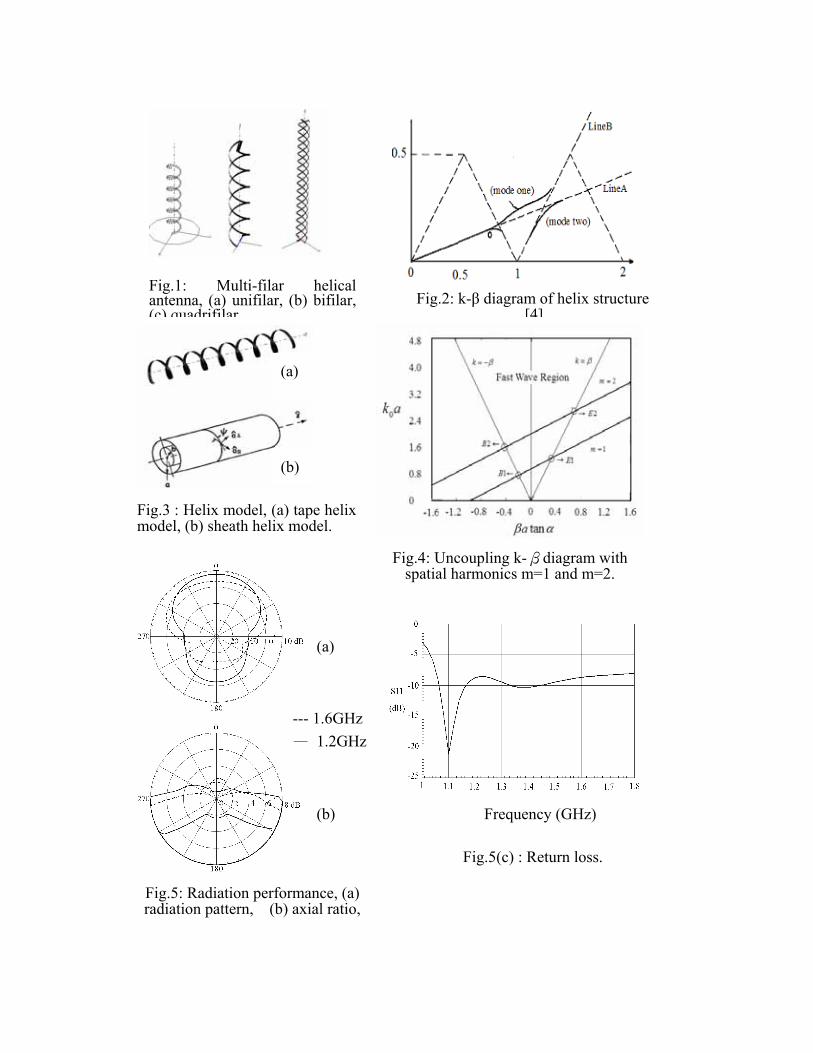
Fig.5: Radiation performance, (a) radiation pattern, (b) axial ratio,
--- 1.6GHz— 1.2GHz
(b)
(a)
Fig.1: Multi-filar helicalantenna, (a) unifilar, (b) bifilar,(c) quadrifilar.
Fig.2: k-β diagram of helix structure
[4].
(a)
Fig.4: Uncoupling k-βdiagram with spatial harmonics m=1 and m=2.
Fig.3 : Helix model, (a) tape helixmodel, (b) sheath helix model.
(b)
Fig.5(c) : Return loss.
Frequency (GHz)
Conclusions The sheath helix model is used to predict the operation of helical antennas.
Design guidelines are based on the uncoupled solution of the sheath helix model. A broadband helical antenna has been introduced which can cover the two existing GPSs.
References [1] A,R Neureuther, P.Wklock, and R.Mittra, “A study of sheath helix with a conducting core and its application to the helical antenna,” IEEE Trans. Antennas Propagat.,vol.15, no.2, Mar. 1967. [2] C.-H. Ho, L. Fan, and K. Chang, “Ultra wide band slotline hybrid ring couplers,” IEEE MTT-S, pp.1175 –1178, June1992. [3] H. Nakano, “Helical and spiral antennas – a numerical approach,” Dept. Elect. Eng. Hosei Univ., Tokyo, Japan. [4] A. T. Adams, R. K. Greenough, R. F. Wallenberg, A. Mendelovicz, and C. Lumjlak, “The quadrifilar helix antenna”, IEEE Trans. Antennas Propagat., vol.22, no.2, Mar. 1974. [5] J. D. Kraus, Antenna, New York: McGraw-Hill, 1950.
Mesh Antennas with Reduced Size
Tze-Hsuan Chang*, Cheng-Wei Lan, and Jean-Fu Kiang Department of Electrical Engineering and
Graduate Institute of Communication Engineering National Taiwan University, Taipei, Taiwan, ROC
E-mail: [email protected] 92-2213-E-002-070
Abstract
In this paper, we propose a new design based on rectangular microstrip antenna, which has lower resonant frequencies or smaller size. Although slightly larger cross-polarization may be induced, but it can be reduced by properly choosing the wire direction. The resonant frequency can be tuned by adjusting the mesh density.
Introduction
Major characteristics of microstrip antennas are their low efficiency, high Q-factor, poor polarization purity and narrow frequency bandwidth. In certain applications, narrow bandwidths are desirable. Lots of researches focus on the shape of patches or the aperture pattern carved on them to obtain broadband or dual-band operation, or circular polarization.
Apertures on the patch can be used to alter or constrain the current flow direction. If the direction of mesh wires follows the surface current distribution of a specific resonant mode, that resonant mode will be excited. If the mesh pattern or the wire perturbs the current distribution, the associated resonant frequency will be varied. In both cases, the radiation pattern and polarization will be affected. However, mesh patterns can be designed carefully to reduce cross-polarization or change the polarization.
Embedding wider arc-shaped slot near the edge of circular patch or loading a U-shaped slot in the microstrip patches of various shapes can achieve broadband operation. If the slot is arranged to be parallel to the current direction of a specific resonant mode, its characteristics will be affected slightly. If the slot perturbs the current of another mode, its resonant frequency can be significantly reduced. Such two resonant frequencies can be brought close to each other and form a wide band [1]
Substrate with thicker and lower dielectric constant can render stronger fringing field and make the approximation of magnetic wall less accurate. The internal fields have less constraint over a wider bandwidth. However, thicker substrate implies longer feeding probe which induces larger inductance and hence narrower bandwidth (<10%). Etching a small circular slot on the patch around the feed location can induce capacitance to compensate for the probe
inductance and increase the bandwidth (16 %) [1].
Inserting a reactive loading on the microstrip antenna can also obtain wide bandwidth. For example, a capacitor can be used as a current sink. Placing a capacitor properly can increase the current path length of a specific resonant mode while not disturbing the other modes. Hence, the perturbed mode will have lower resonant frequency. If the resonant frequency is brought close to the lower one, a wide bandwidth can be achieved [2].
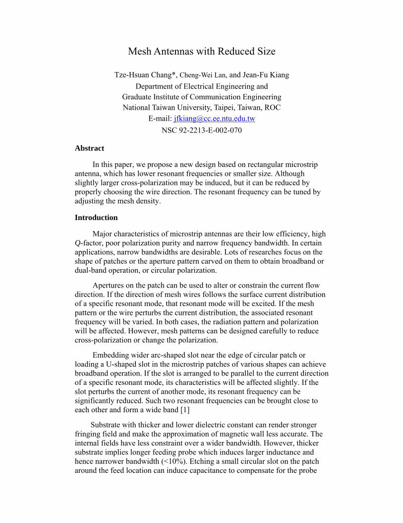
Fig.1 shows the current directions on a wire grid array at resonant frequency. The current on vertical wires are in phase, while each horizontal segment supports a full wave. The vertically polarized field components can be adjusted to add while the horizontally ones cancel. As more loops are added to the grid configuration, the magnitude of the cross-polarized wave is reduced, and the wave radiated by vertical segments is enhanced. The cross-polarization levels can be further reduced by the presence of antiphase couplets and additional null plane [3]. The characteristic line impedances of the vertical elements, which are approximately inversely proportional to width, determine the current of that element. By varying the width of selected grid elements, the current amplitude can be controlled and both co-polarization and cross- polarization levels become adjustable. Additional suppression would occur if element factor and edge effects were included.
Figure 1: Current distribution of wire grid array antenna at resonant frequency. Currents on
horizontal segment pair cancel each other at far field, and currents on vertical segments are in phase and their fields add constructively.
Results and Conclusions
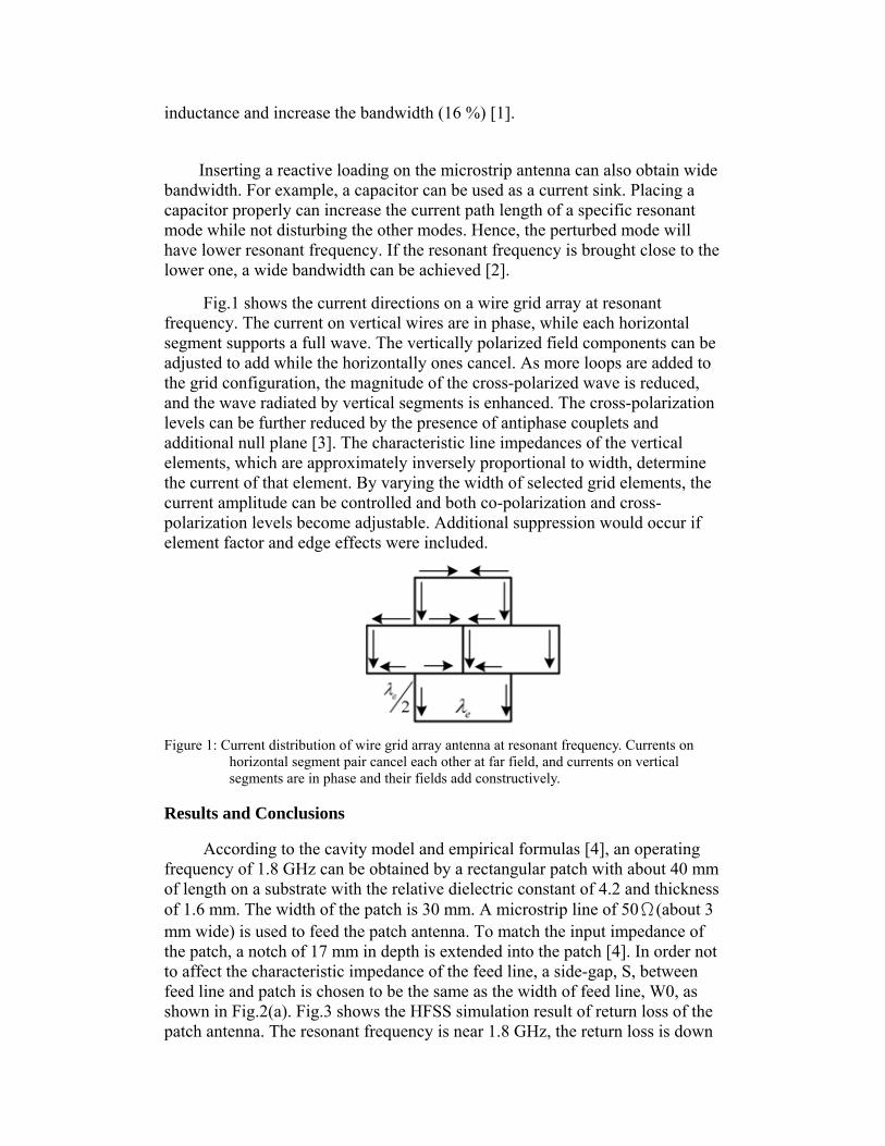
According to the cavity model and empirical formulas [4], an operating frequency of 1.8 GHz can be obtained by a rectangular patch with about 40 mm of length on a substrate with the relative dielectric constant of 4.2 and thickness of 1.6 mm. The width of the patch is 30 mm. A microstrip line of 50Ω(about 3 mm wide) is used to feed the patch antenna. To match the input impedance of the patch, a notch of 17 mm in depth is extended into the patch [4]. In order not to affect the characteristic impedance of the feed line, a side-gap, S, between feed line and patch is chosen to be the same as the width of feed line, W0, as shown in Fig.2(a). Fig.3 shows the HFSS simulation result of return loss of the patch antenna. The resonant frequency is near 1.8 GHz, the return loss is down
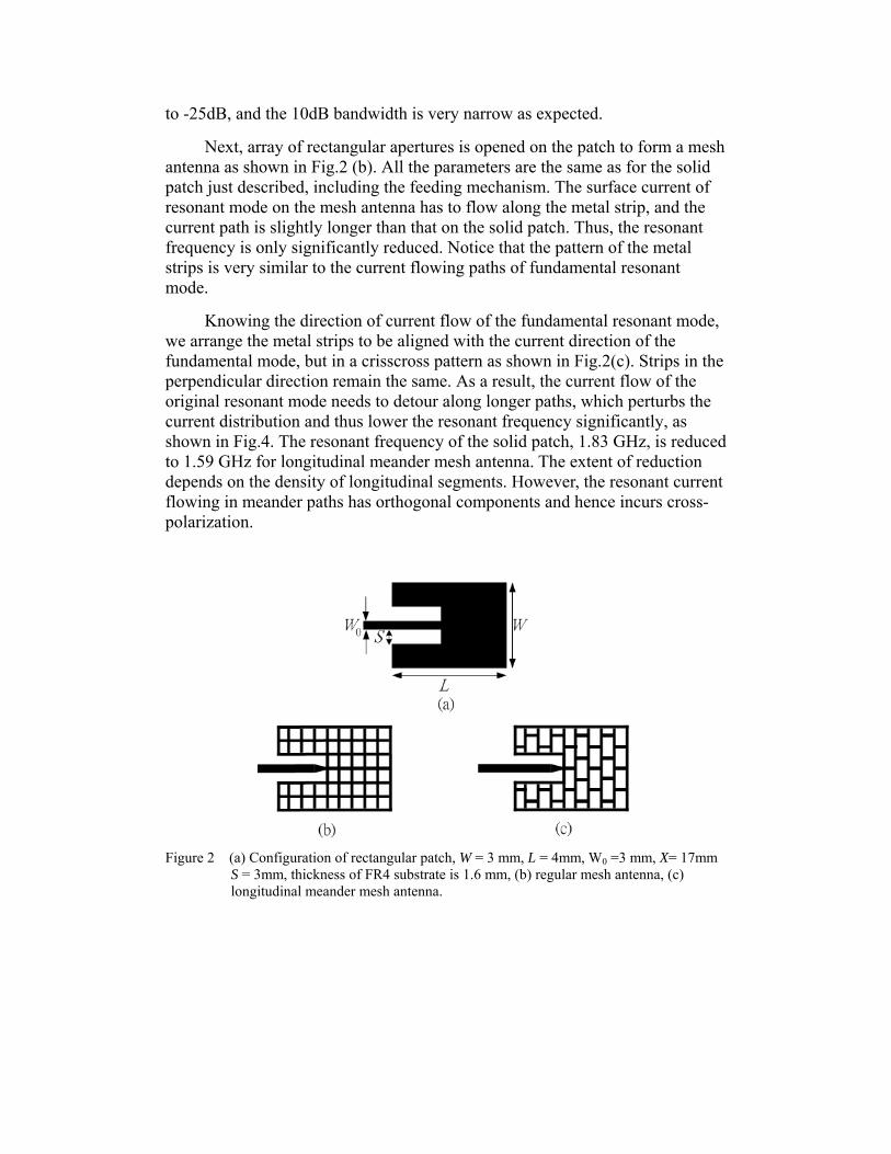
to -25dB, and the 10dB bandwidth is very narrow as expected.
Next, array of rectangular apertures is opened on the patch to form a mesh antenna as shown in Fig.2 (b). All the parameters are the same as for the solid patch just described, including the feeding mechanism. The surface current of resonant mode on the mesh antenna has to flow along the metal strip, and the current path is slightly longer than that on the solid patch. Thus, the resonant frequency is only significantly reduced. Notice that the pattern of the metal strips is very similar to the current flowing paths of fundamental resonant mode.
Knowing the direction of current flow of the fundamental resonant mode, we arrange the metal strips to be aligned with the current direction of the fundamental mode, but in a crisscross pattern as shown in Fig.2(c). Strips in the perpendicular direction remain the same. As a result, the current flow of the original resonant mode needs to detour along longer paths, which perturbs the current distribution and thus lower the resonant frequency significantly, as shown in Fig.4. The resonant frequency of the solid patch, 1.83 GHz, is reduced to 1.59 GHz for longitudinal meander mesh antenna. The extent of reduction depends on the density of longitudinal segments. However, the resonant current flowing in meander paths has orthogonal components and hence incurs cross- polarization.
Figure 2 (a) Configuration of rectangular patch, W = 3 mm, L = 4mm, W0 =3 mm, X= 17mm
S = 3mm, thickness of FR4 substrate is 1.6 mm, (b) regular mesh antenna, (c) longitudinal meander mesh antenna.
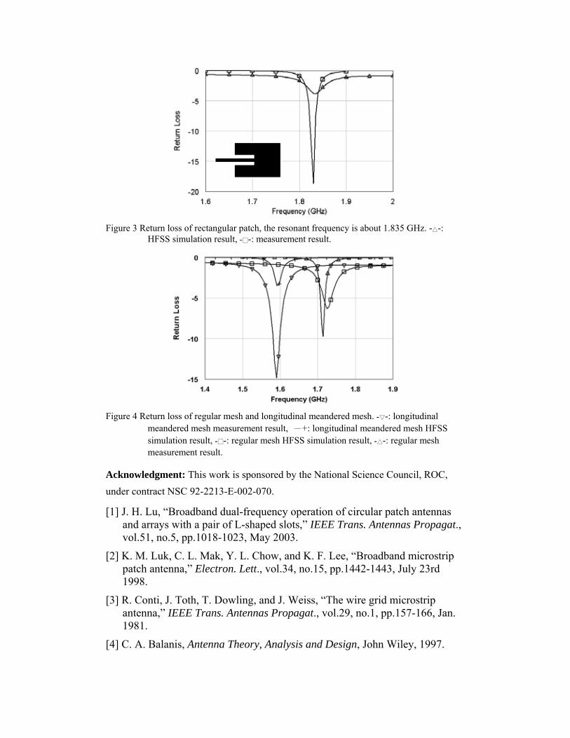
Figure 3 Return loss of rectangular patch, the resonant frequency is about 1.835 GHz. -△-:
HFSS simulation result, -□-: measurement result.
Figure 4 Return loss of regular mesh and longitudinal meandered mesh. -▽-: longitudinal
meandered mesh measurement result, -+: longitudinal meandered mesh HFSS simulation result, -□-: regular mesh HFSS simulation result, -△-: regular mesh measurement result.
Acknowledgment: This work is sponsored by the National Science Council, ROC, under contract NSC 92-2213-E-002-070.
[1] J. H. Lu, “Broadband dual-frequency operation of circular patch antennas and arrays with a pair of L-shaped slots,” IEEE Trans. Antennas Propagat., vol.51, no.5, pp.1018-1023, May 2003.
[2] K. M. Luk, C. L. Mak, Y. L. Chow, and K. F. Lee, “Broadband microstrip patch antenna,” Electron. Lett., vol.34, no.15, pp.1442-1443, July 23rd 1998.
[3] R. Conti, J. Toth, T. Dowling, and J. Weiss, “The wire grid microstrip antenna,” IEEE Trans. Antennas Propagat., vol.29, no.1, pp.157-166, Jan. 1981.
[4] C. A. Balanis, Antenna Theory, Analysis and Design, John Wiley, 1997.
Dual-band Dielectric Resonant Antenna
Tsung-Shan Yung, Tze-Hsuan Chang*, Wen-Zhou Wu, and Jean-Fu Kiang Department of Electrical Engineering and
Graduate Institute of Communication Engineering National Taiwan University, Taipei, Taiwan, ROC
E-mail: [email protected] 92-2213-E-002-070
Abstract
In this paper, dielectric resonant (DR) antennas with inserted slit or well are proposed and verified by HFSS simulation. It is found that broadband and dual-band operation can be achieved by the perturbation of air gap.
Introduction
DR made of low-loss and high-permittivity material has been widely used to implement microwave components. DR antennas are suitable for millimeter- wave due to their low loss. Unlike patch antennas, DR antennas can radiate from all surfaces, rendering high radiation efficiency and low Q-factor [1].
Each resonant mode in DR has different internal field distribution and hence different radiation characteristics. Moreover, mode degeneracy and hybrid modes always exist in spherical DR and cylindrical DR, which increase cross-polarization levels and deteriorate their performance. Resonant frequency of rectangular DR can be uniquely determined by the dimensions of the resonator without mode degeneracy problem. However, rectangular DR antennas are not widely used partially because their resonant modes have not been well categorized [2].
Stacking two DRs of different size increases the operating bandwidth [3]. A conical DR antenna having wide bandwidth is viewed as stacking several resonators with gradual radius change [4]. Placing parasitic DRs on both sides of a driving DR can also increase the bandwidth or obtain dual bands.
Concept and Mechanism
Antennas with lower Q-factor have boarder bandwidth. Thus, the technology of reducing Q-factor has been applied on DR antenna design to increase its bandwidth. Ring structures, which occupy less volume and result in lower Q-factor, are utilized to enhance its bandwidth and obtain higher resonant frequency [5]. It is found that a center-fed cylindrical DR antenna with air gap between the DR and ground plane has a wider bandwidth as the thickness of the gap is increased.
By image theory, the half-split DR with an air gap can be transformed into two half-split DRs separated by an air gap. Thin air gap between the two half-split DRs creates discontinuity of normal electric field at the interface between dielectric and air, and the electric field normal to the interface is much stronger in the air gap than inside the DR. The thin air gap also has significant effect upon the input impedance and resonant frequency. Increasing gap thickness broadens the bandwidth, increases the antenna resonant frequencies, decreases the maximum value of the input resistance, reduces Q-factor, and increases radiation efficiency. However, it is difficult to fabricate. Thus, an air gap inserted into DR antenna is proposed to achieve wider bandwidth and keep the same size as an intact DR antenna.
Results and Conclusions
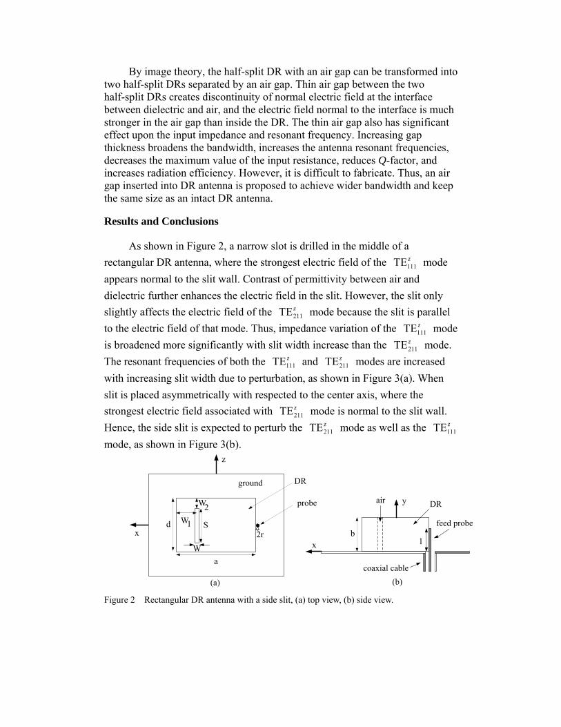
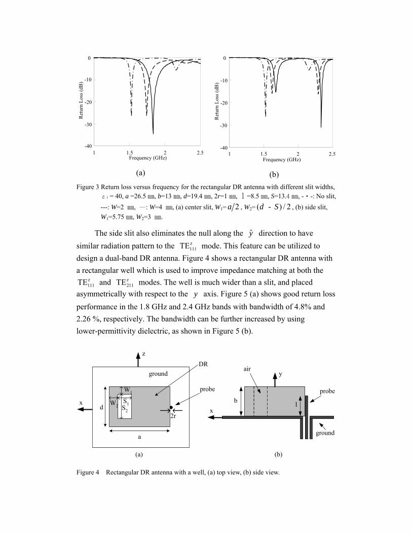
As shown in Figure 2, a narrow slot is drilled in the middle of a rectangular DR antenna, where the strongest electric field of the mode appears normal to the slit wall. Contrast of permittivity between air and dielectric further enhances the electric field in the slit. However, the slit only slightly affects the electric field of the mode because the slit is parallel to the electric field of that mode. Thus, impedance variation of the mode is broadened more significantly with slit width increase than the mode. The resonant frequencies of both the and modes are increased with increasing slit width due to perturbation, as shown in Figure 3(a). When slit is placed asymmetrically with respected to the center axis, where the strongest electric field associated with mode is normal to the slit wall. Hence, the side slit is expected to perturb the mode as well as the mode, as shown in Figure 3(b).
111TE z
211TE z
111TE z
211TE z
111TE z211TE z
211TE z
211TE z111TE z
ground
probe
DR
x
z
a
W1d
W2
S2r
W
(a)
lb
y
feed probe
coaxial cable
DRair
(b)
x
Figure 2 Rectangular DR antenna with a side slit, (a) top view, (b) side view.
1 1.5 2 2.5Frequency (GHz)
-40
-30
-20
-10
0
Ret
urn
Loss
(dB
)
(a)
1 1.5 2 2Frequency (GHz)
.5-40
-30
-20
-10
0
Ret
urn
Loss
(dB
)
(b) Figure 3 Return loss versus frequency for the rectangular DR antenna with different slit widths,
εr = 40, a =26.5㎜, b=13㎜, d=19.4㎜, 2r=1㎜, =8.5㎜, S=13.4 ㎜, -‧-: No slit, ---: W=2 ㎜, —: W=4 ㎜, (a) center slit, W
l
1= 2a , W2= ( - , (b) side slit, W
) / 2d S1=5.75㎜, W2=3 ㎜.
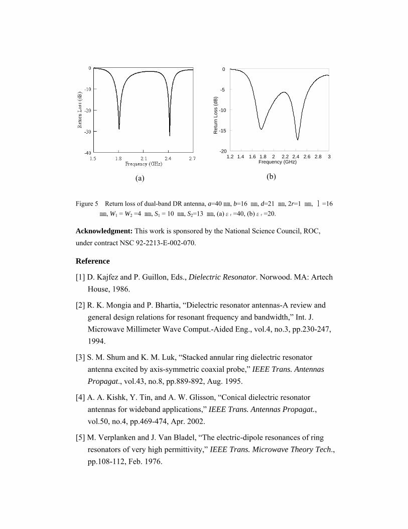
The side slit also eliminates the null along the direction to have similar radiation pattern to the mode. This feature can be utilized to design a dual-band DR antenna. Figure 4 shows a rectangular DR antenna with a rectangular well which is used to improve impedance matching at both the
and modes. The well is much wider than a slit, and placed asymmetrically with respect to the axis. Figure 5 (a) shows good return loss performance in the 1.8 GHz and 2.4 GHz bands with bandwidth of 4.8% and 2.26 %, respectively. The bandwidth can be further increased by using lower-permittivity dielectric, as shown in Figure 5 (b).
y
111TE z
111TE z211TE z
y
a
DR
2r
ground
probe
d
(a)
x
z
x
y
probe
lb
(b)
ground
W1
W2S1S2
air
Figure 4 Rectangular DR antenna with a well, (a) top view, (b) side view.
(a)
1.2 1.4 1.6 1.8 2 2.2 2.4 2.6 2.8 3Frequency (GHz)
-20
-15
-10
-5
0
Ret
urn
Loss
(dB
)
(b)
Figure 5 Return loss of dual-band DR antenna, a=40㎜, b=16 ㎜, d=21 ㎜, 2r=1 ㎜, =16 ㎜, W
l
1 = W2 =4 ㎜, S1 = 10 ㎜, S2=13 ㎜, (a)εr =40, (b)εr =20.
Acknowledgment: This work is sponsored by the National Science Council, ROC, under contract NSC 92-2213-E-002-070.
Reference
[1] D. Kajfez and P. Guillon, Eds., Dielectric Resonator. Norwood. MA: Artech House, 1986.
[2] R. K. Mongia and P. Bhartia, “Dielectric resonator antennas-A review and general design relations for resonant frequency and bandwidth,” Int. J. Microwave Millimeter Wave Comput.-Aided Eng., vol.4, no.3, pp.230-247, 1994.
[3] S. M. Shum and K. M. Luk, “Stacked annular ring dielectric resonator antenna excited by axis-symmetric coaxial probe,” IEEE Trans. Antennas Propagat., vol.43, no.8, pp.889-892, Aug. 1995.
[4] A. A. Kishk, Y. Tin, and A. W. Glisson, “Conical dielectric resonator antennas for wideband applications,” IEEE Trans. Antennas Propagat., vol.50, no.4, pp.469-474, Apr. 2002.
[5] M. Verplanken and J. Van Bladel, “The electric-dipole resonances of ring resonators of very high permittivity,” IEEE Trans. Microwave Theory Tech., pp.108-112, Feb. 1976.


