BRITISH COMPRESSED AIR SOCIETY Installation Guide
185
BRITISH COMPRESSED AIR SOCIETY Installation Guide Guide to the Selection & Installation of Compressed Air Services The Manual for Designers, Constructors, Installers, Engineering Consultants, Specifiers & Users of Compressed Air © Copyright British Compressed Air Society BCAS
Transcript of BRITISH COMPRESSED AIR SOCIETY Installation Guide

BRITISH COMPRESSED AIR SOCIETY
Installation GuideGuide to the
Selection & Installation of Compressed Air Services
The Manual for Designers, Constructors, Installers, Engineering Consultants,
Specifiers & Users of Compressed Air
© Copyright British Compressed Air Society
BCAS

British C om pressed A ir Society 33/34 D evonshire Street London W IN IR F T elephone 0171 935 2464 Facsim ile 0171 935 3077
GUIDE TO THE SELECTION AND
INSTALLATION OF COMPRESSED AIR
SERVICES
4th EDITION
IS BN 0 905608 02X
© BCAS1992

Acknowledgements
The British Compressed Air Society is indebted to many people and companies for the information and advice included in this 4th edition of the Guide to the Selection and Installation o f Compressed Air Services.
It is not possible to list all those who gave advice and assistance, for such a list would have to include those who provided the foundation o f the first edition.
The following companies gave permission to use figures, tables and Nomograms: Atlas Copco (GB) Ltd., British Aeropsace (Dynamics) Ltd., Durapipe Ltd., Norgren Martonair Ltd., Thomas Wright (Bradford) Ltd.
Last but not least we must thank Rogers Knight and Greg Bordiak for their monumental contribution to the updating process.

Contents
Section
1
2
Introduction
Terminology
Assessment of Air Consumption of PlantOperating pressure, maximum and average load, use factor, future expansion, allowance for air leakage, capacity/pressure relationship.
Selection of Compressor PlantAir compressors positive displacement and dynamic, specific power consumption, capacity and pressure limitations, stand-by capacity, load splitting, closed loop systems, output control, prime movers, application requirements, output and site conditions, compressor inlet conditions, evaluating costs, packaged compressors, performance testing.
Selection of Compressor Ancillary EquipmentAftercoolers, air receiver, drain traps, air dryers types and testing, reheaters, gauges, pressure relief valves and protective devices, silencers, filters, distribution piping.
Compressor InstallationType of installation, compressor siting, compressor intake, compressor discharge, cooling water system, ventilation.
Energy Conservation and Heat RecoveryOil grade, control systems, leaks, heat recovery, pressure drops in pipes.
Pages
1-1
2-12-5
3-1
3- 3
4 - 1
4- 6
5- 1
5- 9
6 - 1
6-9
7-17-5
C -1

Section Pages
10
11
12
Main Line InstallationAir mains sizing and siting, materials for pipes and fittings, determination of pipe size, reserve air capacity, accessories, installation, testing the system.
Final Service Line InstallationIndividual drop and feed lines, filters and separators, pressure regulators, air line lubricators and lubricants, blow guns, hose and fittings, quick release couplings, flow limiting valves, flow metering.
Testing the SystemMain and branch lines, leakage, use of flow meters, keeping of records.
8-1
8-8
9-1
9-10
10-110-3
PrecautionsDuring commissioning, safety of personnel, safe use 11-1 of compressed air, eye protection, blow guns, breathing compressed air, mismatching of screw threads, precautions during operation, maintenance, overpressure protection, hot air ducting, circuit diagrams. 11-8
LegislationHealth & Safety at Work Act, etc. 1974Pressure Systems Regulations 1989Factories ActNoise at Work RegulationsSafety of MachinesPressurised EquipmentSimple Pressure VesselsUse of Work EquipmentSuppliers of ServicesManual HandlingWorkplace DirectiveHazardous SubstancesUsed MachineryPersonal Protective EquipmentConstruction Products used in Buildings
12-1
12-6
C - 2

Figure
1
2
3
4
Table
1
2
3
4
Basic Compressor Types.
Compressor Types - Approximate capacity and pressure limitations.
Typical Compressor Installation.
Typical Compressed Air Installation.
Air Consumption of Pneumatic Equipment.
Air Consumption of Cylinders (metric).
Altitude Effect on Compressors
Pressure Drop and Row Rate in Air Mains.4A Row through black iron or steel pipe.4B Row through ABS pipe.
Row Through Pipes and Pressure Loss Through Fittings.
Pages
FI
F2
F3
F4
Pages
Tl-1
T2-1
T3-1
T3-1T4-1T4-2
5A Maximum Recommended Row in steel Main Lines. T5-1
5B Maximum Recommended Row in Branch Lines. T5-2
5C Pressure Loss Through Steel Fittings T5-35D Pressure Loss in ABS Fittings T5-45E Recommended Flow in ABS Pipe. T5-4
6 Typical Standard Air Receivers. T6-1
7 Water Vapour Content and Resulting Dew Point Temperatureat Various Gauge Pressures. T7-1
8 Leakage Loss in Compressed Air Systems. T8-1
9 Intervals Between Pipe Supports.9A Steel Pipe T9-19B ABS Pipe T9-19C Copper Pipe T9-1
C - 3

Table Pages
10 Flow in Tubes and Hoses.lOA Maximum Flow through Copper or Nylon Tubing TlO-1 lOB Pressure Losses in Hoses with End Fittings TlO-2
11 Air Flow Through Nozzles. T ll-1
12 International Standards (ISO)TC5 Ferrous Pipes and metallic fittings. T12-1TC8 Ship Building and Marine Structures T12-4TCI2 Quantities, units, symbols and conversion tables. T12-4 TCI7 Steel (for pressure purpose). T12-4TC19 Preferred Numbers. T12-5TC20 Aircraft and space vehicles. T12-6TC26 Copper and copper alloys. T12-6TC28 Lubricants. T12-6TC29 Small Tools. T12-7TC39 Machine Tools. T12-7TC43 Acoustics. T12-8TC45 Rubber and Plastics. T12-8TCI08 Vibration and Shock. T12-9TCI 12 Vacuum Technology. T12-9TC118 Compressors, pneumatic tools and machines. T12-10TCI 19 Powder Metallurgy. T12-12TCI31 Fluid Power Systems. T12-13TC138 Plastic pipes, fittings and valves. T12-16TC145 Graphical symbols T12-16TC153 Valves. T12-17TCI54 Documents and data presentation. T12-17TCI76 Quality management and assurance. T12-17TCI85 Safety devices against excessive pressure. T12-18
■TCI99 Safety of machinery. T12-18
13 British Standards (BSI).13A Pipes, tubes, hoses, pressure vessels and valves. T13-1 13B Protective equipment and precautions. T13-1613C Filters, dryers and lubricators. T13-1913D Compressors, vacuum plant and pneumatic tools. T13-21 13E Pneumatic control equipment. T13-2713F Symbols, units and tables. T13-30
C - 4

Table Pages
14 European Standards (CEN). T14-1
15 Publications Available from the BCAS. T15-1
16 The International System of Units (SI). T16-1
C - 5

Introduction
Because of the changes in United Kingdom and European Legislation, it is important to note that previous editions of this Guide, that is issues 1 to 3, should no longer be used. Where appropriate this publication has been upgraded to take into account the changes due to legislation. This publication is approximately 40% larger.
Compressed air systems have advantages in safety, cleanliness, flexibility and the ready availability of the medium.To assist the user in selecting the most suitable compressed air system to install and in understanding how such a system can be maintained at a high level of efficiency, the British Compressed Air Society has produced this new and enlarged edition of the Guide to the Selection and Installation of Compressed Air Services.This Guide, whilst comprehensive, is general in nature. Users are, therefore, strongly recommended to consult with equipment suppliers at an early stage before making any final decisions since each installation will present its own individual requirements.
The source of compressed air power, the compressor and its associated equipment, must be selected and maintained with care.In many cases the compressed air system is a major consumer of energy and any decrease in efficiency will adversely affect the overall operating cost of the plant. Chapter 7 deals specifically with this subject.
This Guide has been prepared to assist the user with regard to the majority of compressed air installations, that is those which use pressures between 1.6 and 16 bar gauge. However the Society recommends detailed consultations at an early stage with the equipment supplier not only for such installations but also for systems using gases other than air and for systems using pressures above 16 bar gauge.
The symbol L for litre, which was approved as an alternative to 1 at the 16th me'eting-of-the Conference General des Poids et Mesures (CGPM) in October, 1979, has been used throughout this Guide in order to avoid confusion with the numeral 1.
1 - 1

For the benefit of users not fully familiar with the S.I. system of units which is used throughout the Guide, attention is drawn to Table 16.In particular Table 16.6 supplies easy to use conversion factors from . Imperial.
Compliance with the recommendations made in this ‘Guide’ and the Standards, etc. referred to therein, does not of itself confer immunity from legal obligations. In particular, attention is drawn to the Pressure Systems and Transportable Gas Containers Regulations 1989 and its Approved Code of Practice COP37, as well as the Health and Safety at Work, etc. Act 1974.
It is strongly recommended that readers consult, at an early stage. Chapter twelve to ensure that they are in possession of all essential information on legislative constraints.
1 - 2

2 Terminology
T h e f o l l o w i n g d e f i n i t i o n s w i l l b e c o m e c l e a r e r a s t h e r e a d e r p r o g r e s s e s
t h r o u g h t h i s m a n u a l ; o t h e r t e r m s a r e e x p l a i n e d i n t h e a p p r o p r i a t e
s e c t i o n .
2.1 Absolute Pressure. The pressure with reference to Absolute Zero, that is with reference to an Absolute Vacuum; it equals the sum of the Atmospheric Pressure and the Gauge Pressure(Section 2.22 - Gauge Pressure)(ISO 3857-1).
2.2 Absolute Temperature. The temperature measured from Absolute Zero (ISO 3857-1).
2.3 Actuator. This word has two interpretations:(a) An ‘operating device’ (See 2.28);(b) A working element (See 2.46).
2.4 Adiabatic. Expansion or compression of a gas without loss or gain of heat content.
2.5 Aftercooling. The removal of heat from the air after compression is complete.
2.6 Ambient Temperature. The temperature of the environment in which the equipment is working. The use of the words "ambient temperature" to indicate the temperature of the atmosphere at a point remote from the equipment is incorrect.
2.7 Atmospheric Pressure. The Absolute Pressure of the atmosphere as measured at the place under consideration (ISO 3857-1).
2.8 Buckling Pin Device. A non reclosing pressure relief device actuated by differential pressure and consisting of a piston held onto a seat by means of a calibrated pin which acts as a piston rod. When the pressure beneath the piston reaches a critical value (governed by Euler’s Law) the pin buckles and the piston moves to allow discharge of the system fluid through the seat.
2.9 Bursting disc device. A non reclosing pressure relief device actuated by differential pressure and designed to function by the bursting or venting of the bursting disc(s). (See BS 2915)
2.10 Closed Loop System; A system in which air exhausted from the actuators is returned as a closed pressurised circuit to the compressor inlet.
2 - 1

2.11 Compressor. A device which causes a gas to flow and produce a pressure; it converts mechanical, force and motion into pneumatic fluid power (see 4.1 for definitions of the various types of compressors).
2.12 Compressor Capacity. The actual volume rate of flow compressed and delivered at the standard discharge point, at stated inlet conditions, usually expressed in terms of Free Air Delivered(Section 2.20 - Free Air) (ISO 3857-2).
2.13 Compressor Regulator. A device fitted to the compressor to control the output of the machine.
2.14 Condensate. The liquid formed from water vapour in the air because of a drop in the air temperature and/or an increase in pressure.(See 5.3).
2.15 Dew Point. The temperature at which air is fully saturated with water vapour at the pressure prevailing.
2.16 Displacement. The volume displaced by the compression element of the first stage per unit of time.
2.17 Dryer. A device which reduces the water vapour content of the compressed air.
2.18 Explosion Proof. (Rame proof enclosure) Apparatus placed in an enclosure that can withstand an internal explosion of an explosive mixture without igniting an explosive atmosphere surrounding the enclosure (See BS5501).
2.19 Filter. A device which removes foreign matter from the working medium.
2.20 Free Air. Air at the atmospheric conditions at the inlet point unaffected by the compressor; it is usual for the output of an air compressor to be referred to the stated atmospheric conditions at the inlet, and the consumption of a tool or pneumatic cylinder to be expressed in terms of a standard reference atmosphere (See 2.44). The fetters ANR placed after a rate of airflow expressed in L/s or m^/h indicate that free airflow is being expressed. ANR = Atmosphere Normale de Reference.
2.21 Fusible Plug. A device fitted in the hot discharge zone of a compressor for protection against high temperature.
2 - 2

2.22 Gauge Pressure. The pressure as measured with reference to atmospheric pressure; where no other indication is given, pressures expressed in "bar" are assumed to be gauge pressures (ISO 3857-1).
2.23 Intercooling. The removal of heat from the air between stages in multi-stage compression.
2.24 Intrinsically safe Electrical apparatus in which the electrical circuits themselves are incapable of causing ignition of a surrounding explosive atmosphere (See BS5501).
2.25 Isothermal. Expansion or compression carried out without change of temperature.
2.26 Lubricator. A device which introduces a controlled quantity of lubricant into the working medium.
2.27 Multi-stage Compression. Compression from initial to final pressure in two or more stages (steps) with cooling between each stage.(Section 2.41 - Single Stage Compression).
2.28 Operating Device. A device that provides an input signal to a control component.
2.29 Overall Stage Pressure Ratio. The pressure ratio for any particular stage in a multi-stage compressor, the discharge pressure being measured after the intercooler (including separator), (Section 2.43 Stage Pressure Ratio); this is calculated using Absolute Pressure (ISO 3857-2).
2.30 Pipeline. The pressure Systems Regulations define a pipeline as "a pipe (or system of pipes) used for the conveyance of a relevant fluid( e.g. compressed air) across the boundaries of premises, together with the valves, pumps, compressors and similar works which are annexed to, or incorporated in, the course of the pipe or system". Avoid the use of "pipeline" when referring to the pipes within factory premises which have their own compressor installation.
2.31 Pipework. A term that should not be employed when referring to the pipes that convey cornpressed air. ‘Pipework’ has a special meaning in the context of the Pressure Systems Regulations i.e. A pipe or system of pipes with associated valves, pumps, compressors and other pressure containing components and includes hoses but does not include the air receiver or any protective devices. Avoid the use of ‘pipeline’ also as this has a specific meaning in the Pressure Systems Regulations.(See 2.30).
2 - 3

2.32 Pressure Ratio (Total) The ratio between the Absolute discharge pressure and the Absolute inlet pressure; (ISO 3857-2)See also Section 2.43.
2.33 Pressure Regulator (Pressure Reducing Valve). A device which reduces the line pressure and maintains it relatively constant despite changes in inlet pressure and outlet flow rate.
2.34 Pressure Relief Valve (Safety Valve) A device which limits the maximum system pressure by exhausting the compressed air to atmosphere when the required back pressure is exceeded, also known as a Back Pressure Regulator.
2.35 Protective Device. A term employed in the Pressure Systems Regulations and includes all devices such as pressure gauges, temperature gauges and other items of measuring equipment, pressure relief valves, bursting discs, fusible plugs, excess temperature or pressure shut-down controls which enable system failure to be prevented by keeping it within its safe operating limits.
2.36 Pulsation Dampener. A chamber fitted at the inlet or discharge of a reciprocating compressor to remove pulsations and prevent resonance.
2.37 Receiver, Air. A pressure vessel in which compressed air is stored.
2.38 Relative Humidity. The ratio of the amount of water vapour actually contained in a volume of air at a specific temperature and pressure, to the maximum amount possible under these conditions; normally expressed as a percentage.
2.39 Ring Main. An air main which begins and ends at the compressor so that every outlet has two possible sources (routes) of supply.
2.40 Separator. A device which removes liquids from the compressed air. The word has two general interpretations. A device for removing condensate from the compressed air and a device, forming part of an oil flooded rotary compressor assembly, to remove oil from the compressed air and return the oil to the compressor sump.This latter device is generally known as an air/oil separator.
2.41 Single-Stage Compression. Compression from initial to final pressure in a single stage (step) (Section 2.27-Multi-stage Compression).
2 - 4

2.42 Specific Power Consumption. The shaft power input per unit of compressor capacity (Joules/litre=kW.s/m^) (ISO 3857-2).
2.43 Stage Pressure Ratio. The ratio for any particular stage in a multistage compressor, the discharge pressure being measured before the intercooler (Section 2.29 and 2.32).
2.44 Standard Reference Atmosphere. The agreed atmosphere to which specification values and test results determined in other atmospheres are corrected (ISO 8778); pneumatic fluid power uses Ibar (lOOkPa), 20°C and 65% RH (ISO 8778); the compressor and pneumatic tool industries also use Ibar, 20°C and 65% RH (ISO 2787); the aerospace (ISO 2533) and petroleum (ISO 5024) industries both use 1013 mbar, 15°C and dry at mean sea level.
2.45 Volumetric Efficiency. The ratio of free air delivered, to the actual displacement of a compressor; this ratio is normally expressed as a percentage; condensates, may possibly be taken intoaccount (ISO 3857-2)
2.46 Working element. The component that transforms fluid energy into hnear, rotary or limited rotary movement (e.g. a pneumatic cylinder or pneumatic motor or semi rotary device).
2 - 5

3 Assessment of Air Consumption of a Plant
3.1 The main consideration in the selection of a compressor plant is the production of an adequate supply of compressed air at the lowest cost consistent with reliable service. The installation of a compressed air system, as with all forms of power transmission, calls for capital investment with consequent operating and maintenance costs.The information on which the selection of plant is based should be as accurate as possible.
Before deciding the capacity of the compressor required, it is necessary to calculate the air consumpdon expected. It is recommended that reference is made to Tables 1 and 2 which show typical "use factors" for various types of pneumadc equipment. In some cases, where there is experience of a similar installation, a fairly accurate analysis can be ihade by plotting data obtained from past activity.
3.2 Important factors to be considered are:
3.2.1 Operating Pressure and Flow. Most compressed air equipment operates at about 6 bar (gauge) and it is usual for the compressor to deliver air into the mains at 7 bar (gauge) in order to allow for transmission losses. (See Table 4A, B and 5A, B, C, D and E).If some of the air is to be used at a lower pressure, for example for instrument control, the pressure is reduced by means of a pressure regulator to the required line pressure
All equipment connected to the system shall either have a design pressure greater than the maximum output pressure of the compressor, or special precautions shall be taken to ensure that, if its design pressure is lower than the output pressure of the compressor, it cannot be subject to excessive pressure (See 11.5).
Should there be a requirement for a large volume of air at a higher or lower pressure it may be more economical to install a separate compressor to deal solely with that requirement.
3.2.2 Maximum and Average Load. Ideally the total capacity would be based on exact knowledge of the equipment or process requirements; if this is under-estimated the compressor plant will be too small, and will be unable to maintain the required pressure in the system.
• 3-1

Conversely, if the total air consumption is greatly over-estimated there may be excessive capital investment. Furthermore any arrangement which results in significant off-load running wastes energy.
However, it is safer to err on the high side with a slight over-estimate, as in most installations the use of compressed air will increase and soon take up any surplus capacity (See 3.2.3).
3.2.3 Future Expansion. Future expansion should always be taken into account when installing new plant. Increasing compressor capacity presents no problem provided that the rest of the plant installation has been planned accordingly. (See 8.3).
With modem rotary compressors it will usually be more economical in both capital and running costs to install an additional compressor ra^er than purchasing a new compressor of larger capacity.
3.2.4 Air Leakage. Experience has shown that the initial estimate of the total compressor capacity should include an allowance for leakage.
Leakage in the piping systems, can be overcome by proper installation practice, a large proportion of the total leakage occurs at hoses, couplings and valves.For an installation with regular inspection and maintenance leakage should not exceed 5% (Section 10.2 - Testing for Leakage).The importance of this is obvious when one remembers that whilst a tool or appliance may use a considerable amount of air, it is only working intermittently, whereas any leakage even from a small hole is both continuous and significant.(See Table 8).Leakage is often caused by insufficient attention to the matching of screvv^ threads [See 11.4.1(m)]. Excessive leakage may also indicate corroded pipes or faulty pipe joints which might lead to the sudden release of stored energy which is a ‘system failure’ in the context of the Pressure Systems Regulations (See 12.2).
3 - 2

3.2,5 Capacity/Pressure Relationship. The amount of any additional capacity needed can be calculated from the known pressure and capacity of the present system.
Vi = Present free air capacity in L/s A l^?2 = Original mains pressure at full demand (bar absolute)Pi = Present mains pressure at full demand (bar absolute)V2 = Required total free air capacity at full demand
W l = W 2 ^ e.g. VI = 300 L/s ANR PI P2 V2 = ?
P2 = 7 bar gauge PI = 5.5 bar gauge
V2 = 300 (7+1) = 369 L/s ANR(5.5 + 1)
Since the present capacity is 300L/s ANR an additional capacity of at least 69 L/s is needed in order to restore the mains pressure to 7 bar at full demand.
3 - 3

Selection of Compressor Plant
4.1 Air Compressor. The principal types of compressors and their basic characteristics are outlined below (See also Figure 1).
4.1.1 Positive Displacement Compressors. Positive displacement units are those in which successive volumes of air are confined within a closed space and elevated to a higher pressure. The capacity of a positive displacement compressor varies marginally with the working pressure.
(a) Reciprocating Compressors. The compressing and displacing element (piston or diaphragm) has a reciprocating motion.The piston compressor is available in lubricated and non-lubricated construction.
(b) Helical and Spiral-Lobe Compressors (Screw). Rotary, positive displacement machines in which two inter-meshing rotors, each in helical configuration displace and compress the air; available in lubricated and non-lubricated construction; the discharge air is normally free from pulsation.
(c) Sliding Vane Compressors. Rotary, positive displacement machines in which axial vanes slide radially in a rotor mounted eccentrically within a cylindrical casing. Available in lubricated and non-lubricated construction; the discharge is normally free from pulsation.
(d) Two impeller Straight Lobe Compressors and Blowers. Rotary positive displacement machines in which two straight, mating but non touching lobed impellers, trap the air and carry it from intake to discharge. Non-lubricated; the discharge is normally free from pulsation; low pressure.
(e) Scroll Compressor. Rotary, positive displacement machine in which rotating and fixed elements, non contacting, interact to progressively compress the air. Non lubricated; the discharge is normally pulse free, low volume air output.
4 -1

4.1.2 Dynamic Compressors. Dynamic compressors are rotary continuousflow machines in which the rapidly rotating element accelerates the air as it passes through the element, converting the velocity head into pressure, partially in the rotating element and partially in stationary diffusers or blades. The capacity of a dynamic compressor varies considerably with the working pressure.
(a) Centrifugal Compressors. Acceleration of the air is obtained through the action of one or more rotating impellers; non-lubricated; the discharge air is free fi-om pulsation; very high rotation speed.
(b) Axial Compressors. Acceleration o f the air is obtained through the action o f a bladed rotor, shrouded at the blade ends; non-lubricated; very high rotation speed; high volume output.
4.1.3 Specific Power Consumption. This varies with the size and type of compressor; consultation with the supplier is advised.
4.2 Capacity and Pressure Limitations. Figure 2 shows the approximate capacity and pressure hmitations of each type of compressor.There are areas where more than one type of compressor will provide the required capacity and pressure; in such cases other characteristics such as those given in preceding paragraphs and the type and. pattern of use will govern the selection. Consultation with the supplier is advised.
4.2.1 Compressor Stand-by Capacity. On many installations it is normal to plan the number of compressor units and their output so that there isa stand-by-capacity to permit one unit to be shut down for servicing. Where a constant supply of air is essential to operations, stand-by compressors are a necessity or a facility should be provided for coupling in a compressor. [See 11.4.1(b)]
4.2.2 Load Splitting. In all installations consideration should be given to having at least two compressors to allow for conditions of light load and for maintenance.
4 - 2

4.2.3 Closed Loop Systems. The same general considerations listed above apply to two level closed loop systems but the required input power to the compressor will be considerably reduced or a smaller compressor can be used (see Section 2.10).
4.3 Output Control. A wide range of controls is available to match compressor output to demand. Consultation with the equipment supplier is essential. The output of a compressor can be controlled by several methods as outlined below. The following functions can be performed by pneumatic, hydro-pneumatic and electronic devices.
4.3.1 Reciprocating Compressors.
(1) Intermittent operation using automatic stop/start mechanism.(2) Constant speed running with inlet valve blocking or intake, throttling or external bypass or inlet valve unloading or clearance pocket.(3) Variable Speed.(4) Combinations of (1), (2) and (3) above.
4.3.2 Rotary Sliding Vane Compressors.
(1) Intermittent operation using automatic stop/start mechanism.(2) Constant speed running with inlet valve blocking or intake throttling or external bypass.(3) Variable speed; minimum rotational speed must be high enough to ensure that the blades remain in full contact with the stator.
4.3.3 Rotary Screw Compressors.
(1) Constant speed running with external bypass or intake throttling coupled with blow-off to atmosphere.(2) Variable speed.
4.3.4 Dynamic Compressors.
(1) Constant speed running with intake throttling coupled with blow-off to atmosphere.(2) Variable speed.
4 - 3

4.4
4.4.1
4.4.2
Advice should be sought from the supplier as to the best type of control to suit a particular application.
Selection of Compressor Prime Movers. An important factor in obtaining an economical plant is the selection of an appropriate compressor drive.
The most common power units are;
□ E lectric m otor;□ E n g ine-d iese l, petrol, g a s e tc .□ T u rb in e -g a s , s te a m e tc .
Among the advantages of electric motor drive are compactness and ease of control. The internal combustion engine is preferred for mobile units, emergency standby units, or where electric power is not available. (See also 7.3.3)
A turbine drive is preferred where it helps balance the energy system of a plant or where the steam or gas can be further used. This type of drive permits easy speed control and conserves energy.Regardless of the type of prime mover, professional advice should be taken in matching prime mover to compressor.
Application Requirements. To avoid delays in the preparation of estimates and to avoid unnecessary expense for both buyer and supplier; it is important that all necessary data should be available and be recorded.The parameters which must be established are outlined below; Compressor Output Conditions .(a) Volume of Free Air required (litres per second or cubic metres per hour) including an allowance for future expansion.(b) Minimum discharge pressure required to maintain an acceptable working pressure at the point of use.(c) Quality of air; degree of cleanliness required(see PNEUROP Publication 66110, listed in Table 15).(d) The purpose for which the air is to be used.(e) The pattern of demand for air; continuous or intermittent consumption.
4 - 4

(f) Estimated operating hours per day/week.(g) Type of control (see Section 4.3)(h) The need for ah air receiver.(i) Any special conditions which the compressor must satisfy.(j) Requirements for ancillary equipment, for example water pumps, valves, piping, anti-vibration mountings, aftercoolers, dryers, intake filters and silencers, etc.(k) The protective devices that the compressor manufacturer is required to supply.
4.4.3 Site Conditions.(a) Whether a stationary, transportable or mobile unit is required.(b) Where air is used as a cooling medium, the temperature range should be specified.(c) Where water is used as a cooling medium, the temperature, pressure and quantity of available cooling water should be specified.
(d) Type and level of contaminants in the cooling water supply; need for water analysis.(e) Type of prime mover required and power supply conditions;(to include access to all characteristics, specifications and drawings).(f) Full details of proposed location (to include details of geographical location and ground strata) [See also 4.4.4(d)].(g) Whether the supplier is to install the plant.(h) Availability of off-loading facilities, and the capacity of handling equipment.(i) Local restrictions on noise and the maximum permissible noise level.(j) Vibration sources which may affect the compressor installation.
4.4.4 Compressor Inlet Conditions.(a) Inlet pressure; atmospheric or as specified.(b) Inlet temperature and range.(c) Maximum expected relative humidity, at ambient conditions.(d) Altitude; this will affect power requirement and efficiency.(Consult supplier) (See Table 3).(e) Degree of contamination of available inlet air.[Tables of Temperature, Relative Humidity, Precipitation Levels and Altitudes for most parts of the world are available; published by the Meterological Office and available from HMSO.]
4 - 5

4.5 Evaluating Costs. For the purpose of this Guide the various sizes of compressor are classified into three groups as follows:
□ Sm all-U p to 4 0 ty s□ M edium -40L /s to 300L /s□ L arge-A bove 300L/S
In order to determine the type of compressor most suitable for a particular requirement, an evaluation of the installation, operating and maintenance costs should be made.Relevant factors are:
□ Efficiency-a high d e g re e of efficiency g iv e s a low specific p o w e r consum ption (Jou les/litre = kW. s/m®).
□ P o w e r co st. (S e e 7.3)n ReliabilityG M ain ten an ce cost.□ C ooling C ost.G S u p erv is io n cost.G S p a c e requ irem en ts-inc lud ing a c c e s s for m a in ten an ce .G E a s e of instailation-inciuding availability of lifting d e v ices .G A c c e s s to m ain se rv ice s .G Electrical eq u ip m en t - th e u s e of s ta n d a rd m o to rs a n d s ta r tin g eq u ip m en t is d esirab le .G Availability of s p a r e s a n d serv ice facilities.
4.6 Packaged Compressors. Many modem compressor designs come as a fully equipped package including the aftercooler and control gear and require no special foundation. Most of these packages are air cooled and only need connection to electrical supply, outlet air pipes and to a suitable system of condensate drainage. (See 5.3).They are usually housed in a sound deadening enclosure providing a low noise level thus permitting them to be sited anywhere in the factory instead of in a special compressor house. Their abihty to be sited almost anywhere is of particular value when heat recovery is practised. (See 7.3.1). Adequate ventilation for cooling air must be provided.
4.7 Performance testing. Attention is drawn to the PNEUROP/CAGI Acceptance Test Codes PN2CPT C l, C2 and C3, which provide advice on the conditions to be met and measuring methods to be adopted to verify compressor performance. (See Table 15).
4 - 6

5 Selection Of Compressor Ancillary Equipment
T h e f o l l o w i n g l i s t i n d i c a t e s t h e v a r i o u s i t e m s o f a n c i l l a r y e q u i p m e n t
w h i c h a r e i n g e n e r a l u s e i n c o m p r e s s o r i n s t a l l a t i o n s . S o m e o f t h e s e
i t e m s m a y b e o m i t t e d , d e p e n d i n g o n p a r t i c u l a r r e q u i r e m e n t s
( s e e F i g u r e 3 ) .
5.1 Aftercooler. When atmospheric air is compressed, the temperature of the air increases. This allows the now smaller volume of air to retain, still mostly as vapour, the original moisture vapour present in the atmosphere. The air leaving the compressor and passing through the pipes cools considerably and its ability to retain the moisture vapour is reduced, thus it deposits moisture vapour as water in the pipe.
The most effective way of removing the major part of this condensate is to cool the air immediately after it leaves the compressor, and to drain the condensate. Air leaving an aftercooler will still contain water vapour and further cooling will cause this to condense out (Section 5.4-Air Dryers and 9.2-Filters/Separators).
The cooling of the air and removal of the condensate results in a more reliable plant by reducing corrosion in pipes and equipment, and by removing some of the oil carry-over. In multi-stage compressors a proportion of the moisture vapour is removed in the intercoolers between the compression stages. It is essential that space is available so that the tubular elements of an aftercooler can be removed for cleaning or replacement. A moisture separator should always be fitted to the air discharge side of the aftercooler preferably with an automatic drain.
Normally aftercoolers are equipped with a safety valve, pressure gauge and drain valve. It is recommended that thermometer pockets for air and water are included.
Aftercoolers shall be constructed to comply with the regulations relating to pressure vessels in the country of use.
5 - 1

5.1.1 Types of Aftercooler. The most commonly used types of aftercoolersare;-
(a) Air Cooled. These consist of a nest of tubes through which the compressed air flows and over which a forced draught of cold air is passed by means of a fan assembly.With air cooled aftercoolers, it should be possible to cool the compressed air to a temperature less than lO^C above that of the air which is used as the cooling medium.
(b) Water cooled. These consist essentially of steel shells housing a nest of tubes with water circulating either inside or outside the tubes with the compressed air on the other side, usually arranged so that their flow is in opposite directions through the cooler. With a water cooled aftercooler, it should be possible to ensure that the temperature of the air discharged from the aftercooler is no more than lO^C above that of the cooling water inlet. (See section 6.5).
5.2 Air Receiver. An air receiver absorbs pulsations in the discharge lines from the compressor, smooths the flow of air to the service lines and compressor controls, and serves as a reservoir for momentary demands in excess of the compressor’s output (Section 8.4-Reserve Air Capacity).
In order to determine the required capacity of an air receiver, the compressor output and the pattern of demand for air must be taken into account. As a guide in sizing the air receiver, at normal compressor pressure the capacity of the air receiver (in litres) should be between 6 and 10 times the free air output of the compressor (litres/second). Table 6 gives a range of typical air receiver sizes.
A further benefit of an air receiver is that it precipitates condensate which may be present in the air; this must be removed (Section 5.3- Drain Traps). The air receiver should be placed in the coolest possible location. In cases where the ambient air is corrosive the air receiver may need a special internal finish. If this is considered necessary, the suppliers should be consulted before manufacture commences.
5 - 2

An air receiver shall be fitted with a pressure relief valve, pressure gauge, inspection openings, drain cock, identification plate (BS 5169, EN286 Pt.land BS 6244) and supporting feet. Sufficient external access must be provided to allow visual inspection all round the air receiver shell.
The receiver shall be marked so as to comply with the requirements of Schedule 4 of Statutory Instrument 2169:1989 Pressure Systems Regulations, or the EEC Directive 87/404 relating to Simple Pressure Vessels which is now enacted in UK legislation as Statutory Instrument 1991 No.2749 The Simple Pressure Vessels (Safety) Regulations 1991.
Air receivers shall be constructed to comply with the regulations relating to pressure vessels in the country of use. When the vessel is to be exported, the supplier should be informed and given the name of the country of use. This information should be given before placing the order so that there is sufficient time for the vessel to be designed in accordance with the requirements of the importing country.
Attention is drawn to the fact that vessels constructed to EN 286 Part 1 are acceptable throughout the EC. However, this standard has an upper limit of 10,000 bar-litres.BS5169 has been amended to exclude vessels within the scope of EN286 Part 1. A vessel of 10,000 bar-litres would normally be used with a compressor not exceeding 50kW power input. Air receivers can also be constructed to BS5500.
Where an infrequent demand for a volume of compressed air, in excess of the regular demand, is required a receiver could eliminate the need to have an excessively large compressor to meet the higher demand.The useful storage capacity of a receiver is the volume of free air which can be drawn from the receiver over the permissible pressure drop.The size of the receiver must be proportioned to provide the storage capacity required. (See Section 8.4 Reserve Air Capacity).
5 - 3

5.3 Drain Traps. The draining of moisture, oil, etc, from intercoolers, after-coolers and air receivers may be effected by manual operation of a valve. However, this method can be inefficient unless a definite programme of draining is adhered to, and can be wasteful if a drain valve is left partially open. It is much better to drain automatically by fitting a suitable heavy duty automatic drain trap at all points of drainage. The trap should have a by-pass arrangement to permit manual draining during servicing of the trap.
The condensate which may be heavily contaminated with compressor lubricant shall not be permitted to discharge to ground [Water Resources Act 1991, Part Iff; Ch. II, Sec. 85 (4)(a)] or to sewer.If this drain trap is fitted with a drain line this should comply with the equipment manufacturers requirements in respect of the minimum bore, maximum length and maximum lift of condensate discharge, above the drain trap level.
Special equipment is available to treat condensate heavily contaminated with oil. This separates the oil from the water and enables the water to be discharged to sewer with the oil retained ready for disposal.The maximum amount of oil/water mixture permitted to be discharged directly to sewer varies according to the requirements of each local water authority but a typical maximum figure is 50mg/L of oil/water.
5.4 Air Dryers. Water in compressed air systems can give rise to one of several of the following indirect costs:(a) Production losses from water damage to production machinery or instrumentation.
(b) Spoilage of product.(c) Rusting of pipes which will lead to leaking traps, joints and valves etc. and may lead to actual failure of the pipes.
(d) Water damage to pneumatic instruments, cylinders and tools.
(e) Clogging of hygroscopic materials in bulk handling systems.
5 - 4

The use of aftercoolers for the removal of moisture has previously been described (see Section 5.1). They normally cool the air to within 10 C of the temperature of the cooling medium. However, the temperature of the compressed air leaving the aftercooler is normally higher than that of the air surrounding the pipes through which the compressed air passes; this cools the compressed air yet further, thus condensing more of the vapour into water.
The most effective way to prevent condensation occurring in a compressed air line is to ensure that the air has a pressure dew-point below the temperature to which any part of the system will be exposed for an appreciable period of time. This can be achieved by use of an air dryer (Figure 3 and Table 7).
5.4.1 General Consideration. Of the types of dryer readily available the refngerant type and the desiccant or adsorption types are the most common. When selecting an air dryer it is necessary to bear in mind the required duty, and to consider the capital, running and maintenance costs.
For general purposes, such as process air lines where the ambient air temperature is expected to remain above O C, either a refrigerant or desiccant dryer may be used.
For dew-point requirements of 0®C and below, that is air subject to sudden expansion or where pipelines are run outside a building, a desiccant dryer is necessary.
Where compressed air may come into contact with chemicals, pharmaceuticals, hygroscopic materials and electronic components etc. a desiccant dryer may be essential.
5.4.2 Refrigerant Air Dryer. These are mechanical units with one or moreheat exchangers coupled to a refrigeration circuit. A refrigerant unit can cool to a pressure dew-point of less than 3°C at any permissible working pressure.
5 - 5

5.4.3 Desiccant or Adsorption Dryer. An adsorption agent is contained ina chamber through which the compressed air passes. A typical pressure dew-point at 7 bar is minus 40°C. Twin chambers, with automatic changeover, are normally employed to permit regeneration of the desiccant in one chamber whilst the other is drying the compressed air. A portion of the dried air is usually drawn off, passed through the chamber being regenerated, and discharged to atmosphere.
5.4.4 Deliquescent or Chemical Absorption Dryer. The compressed air is passed through a vessel containing a chemical which reacts with the moisture, forming a solution which is drained from the bottom of the vessel. This type of dryer can usually depress the pressure dewpoint between 8°C to 11°C below its inlet air temperature. This normally results in a pressure dewpoint 1°C to 6°C below ambient temperature depending on the efficiency of the aftercooler and the location of the dryer. In order to obtain a pressure dewpoint in the region of +10°C the inlet air temperature to the dryer should not exceed 20°C.Periodic re-charging is necessary.
5.4.5 Membrane Dryers. The compressed air is passed into the interior of a number of permeable hollow membranes arranged as a bundle of tubes. Water vapour and some of the air permeates the membranes and escapes,to atmosphere. The pressure dewpoint can be varied between +10°C to below -20°C by adjusting the flow rate to the dryer. Membrane dryers should not be used for the supply of breathing air as they can cause oxygen depletion.
5.4.6 Specification and Testing. Attention is drawn to: ISO 7183 (BS 6754) Compressed Air Dryers - Specification and Testing, and in particular the need for the user to specify:(a) Minimum and maximum working pressure.(b) Maximum inlet air temperature.(c) TVpe of application including intended location of the dryer e.g. upstream or downstream of an air receiver.(d) Maximum and minimum ambient temperature at the dryer position.(e) Required pressure dew-point temperature or class (see ISO 8573-1).(f) Volume of air available at the dryer inlet (L/s ANR).(g) Volume of air L/s ANR required at outlet. (See 5.4.3)
5 - 6

(h) Demand pattern, for example, steady, variable with peaks exceeding normal flow rate, shift/24-hour operation etc.(i) Acceptable pressure drop across the dryer.(j) Construction code for the pressure vessel, if relevant.(k) Degree of protection to be provided by the enclosure (see BS EN60529).(l) Type and capacity of available power supply.(m) Level of contamination in the compressed air at the dryer inlet (if known) e.g relative humidity, water content, oil aerosol, solids etc. This information will help the dryer manufacturer to select the most appropriate filtration equipment to protect the dryer.
5.4.7 Consultation with Suppliers. It should be remembered that this isonly a general guide and it is always advisable to contact the suppliers of each t)q)e of plant before making a final decision.
The performance of a dryer is affected by both temperature and pressure. High inlet pressure and low ambient and inlet air temperature improves dryer performance and vice-versa.It is therefore important to inform the supplier regarding the lowest pressure and highest ambient and inlet air temperature expected at the site, thus ensuring that the correct type and model of dryer will be supplied (see also 5.4.6). The supplier should be requested to indicate the performance of the dryer at Standard Reference Conditions (ISO 7183-BS 6754) as well as the expected performance at the specified site conditions.
5.5 Re-heaters. These are heat exchangers for re-heating the compressed air in order to increase its volume and to reduce the relative humidity. The re-heating of the air prior to its use in an air-operated machine can eliminate freezing-up of exhaust ports by lowering the relative humidity of the compressed air. If a high proportion of the moisture and oil have been separated and drained off before reaching theair mains, the air can be re-heated without the danger that further cooling might lead to condensation of moisture vapour in the system. Great care must be taken in the selection and use of re-heaters bearing in mind the explosion risk. Before installing reheaters consideration should be given to the alternative of an air dryer.
5.6 Gauges and other protective devices. An inoperative or inaccurate gauge or switch may present a safety hazard.
5 - 7

5.6.1 Pressure Gauges. All compressed air systems should be provided with pressure gauges for measuring the pressure of intercooler air, discharge air, lubricating oil and cooling water, where relevant.Pressure gauges should also be fitted at each point of use of the compressed air in order to verify safe and satisfactory air pressure. Pressure gauges should be selected with proper regard given to quality and should be checked for accuracy at regular intervals.(See EN 472 in course of preparation.)Both the working life and accuracy of a pressure gauge are reduced by pressure surges and vibration. The effect of the former can be reduced by fitting damping devices, commonly called snubbers, at the gauge inlet. If the gauge cannot be mounted so as to be isolated from the source of vibration the solution is to use a liquid filled gauge which will also reduce the effect of the pressure surges. The advice of the gauge manufacturer should be sought with regard to the most suitable liquid to be used to fill the gauge as this will be governed by site conditions. [See also Section 11.5(d)]
5.6.2 Temperature Gauges. Should be fitted to cooling water, air discharge, lubricating oil systems and aftercoolers.
5.7 Protective Switches. Thermostatic switches should be fitted to prevent overheating in air, oil and water circuits. It is prudent to fit flow switches in the water cooling circuit.
5.8 Pressure Relief Valve. The discharge line (inter-stage or final) of any positive displacement compressor shall be fitted with a pressure relief valve which relieves the pressure when this exceeds the maximum allowable working pressure of the respective stage by 10%(See BS 6244).
5.9 Air Discharge Silencer. In order to reduce air discharge noise, silencers tuned to the appropriate sound frequency can be fitted in the discharge line close to the compressor. The silencer should offer minimum resistance to the airflow.
5 - 8

5.10 Air Vent Silencer. If a compressor off-loads through a venting pipe to atmosphere consideration should be given to fitting a coalescing type silencer to remove and collect oil mist.
5.11 Air Intake Silencer. When arranging the air intake system it is essential to consider the problem of noise, particularly if the intake is near office or residential premises [Section 4.4.3 (i)]. Silencers can be fitted and should offer minimum resistance to the airflow.
5.12 Air intake Filter. One important condition for the reliability and durability of a compressor is that it must be provided with a suitable and efficient intake filter. Excessive wear is caused mainly by the abrasive effect of impurities in the intake air.
5.13 Cooling Water Filter. It is recommended that the cooling water be filtered [See 4.4.3 (d)].
5.14 Distribution Piping. Pipes manufactured from steel, ABS (a ductile thermoplastic material), copper, stainless steel and aluminium are suitable for conveying compressed air. Recommended service conditions and general data on materials are given in Section 8.2 for air mains,9.1 for individual drop and feed lines and 9.5 for hose and fittings.
Plastic pipes other than ABS should not be used unless the supplier has confirmed their suitability for compressed air systems (See 8.2.2). Attention is drawn to the need to correctly match screw Sireads.- [See 11.4.1 (m)]
5 - 9
6 Compressor Installation
6.1 Type of Installation. When planning a compressor installation one of the first matters to be decided is whether there should be a central compressor plant or a number of separate compressors near the main points of use. The following remarks can be no more than general.In order to select the type and size of installation which will be adequate for both immediate and future requirements it is advisable to consult the supplier (see also Section 4).
Points to be considered are as follows:
6.1.1 Centralized Installation.(a) Lower total installed compressor capacity and, possibly, lower initial cost.(b) Possibly a higher efficiency, and thus lower power cost, due to larger units.(c) Lower supervision cost.(d) It may be easier to arrange for heat recovery especially if required for water heating
6.1.2 Decentralized Installation.(a) Output and/or pressure can be varied to suit each particular plant section.(b) Pipe sizes can be reduced, thus minimising leakage and cost.(c) Compressors and/or associated equipment can be shut down during periods of low demand or for preventative maintenance with only a localized effect (See also Section 1 . 2 2 . 5 ) .
(d) If heat recovery is in the form of hot air decentrahsed units permit several sites to be supplied.
6.2 Compressor Siting. The requirements for a compressor site will be affected by location and climate as well as by the equipment to be installed. The following aspects should be considered;
6-1

6.2.1 Foundations. The compressor plant should be located in a place with good ground conditions. In some cases the compressor foundation may have to be isolated from the main building foundation so that vibration is not transmitted from compressor to the building structure, and from heavy plant to the compressor. Where the vibrations are slight, resilient pads may be used to advantage. Receiver mounted units should always be either free-standing or mounted on resilient pads.
Modem packaged compressors do not require special foundations and may be sited anywhere within the factory that is convenient for the air supply or heat recovery.If in doubt refer to your suppliers.
6.2.2 Servicing Facilities. For small and medium compressors lifting gear is n e c e s s^ only for installation or re-siting, no special hoisting equipment being Tiormally needed when overhauhng the units provided individual components do not exceed the limits specified in the guidelines to the regulations which enforce the European Directive 90/269/EEC "Manual Handling of Loads". (See 12.10). On larger units, lifting equipment is essential; the manufacturer or supplier must state the maximum hoisting load. Sufficient access and headroom must be provided around the compressor for servicing.
6.2.3 Weather Protection. Adequate protection from the weather must be provided, unless the compressor is specifically designed for outdoor operation
6.2.4 Ventilation. Heat generated by the compressor and prime mover must be dispersed. For air-cooled units sited in enclosed rooms and packaged compressors this heat must be removed in order to limit the temperature rise, it is sometimes possible to recover this heat for use elsewhere. Intake openings should be located so that dust and other foreign matter including fumes does not enter with the air.
6.2.5 Noise. Noise from a compressor plant arises at different sources and each source has its own pattern of sound pressure levels. Noise levels can be divided into two groups, the low frequency pulsating air intake sound and the higher frequency machine noise from compressor, prime mover and fans.
6- 2

Local statutory regulations on noise levels should be determined, and action taken by the supplier to ensure the noise levels do not exceed those stipulated.
6.3 Compressor Intake.
6.3.1 General. The compressor intake air must be clean and free from solid and gaseous impurities; abrasive dust and corrosive gases are particularly harmful. Exhaust fumes present a hazard if compressed air is required for breathing purposes. The possibility of contamination of the intake by discharge from pressure relief devices of other plant must be taken into consideration and changes of wind direction must not be overlooked.
For maximum efficiency the intake air should be as cold as possible a temperature decrease of 6®C will increase the mass of the delivered air by 2%. The air intake system should be sized to give a minimum pressure drop, (Section 6.3.4 - Intake Ducts).Each compressor should have its own intake filter.
The reciprocating compressor inspires air in a series of pulsations which causes an equivalent variation in pressure in the intake system. Dependent on the length of the intake pipe, resonance may occur; this can decrease the compressor output and produce disturbing noise levels and stress sufficient to cause damage. By fitting a pulsation dampener or changing the length of the intake pipe, its natural resonant frequency can be changed, and any related vibration, noise and interference (with air flow) will be diminished. The inherent pulsation noise can be removed by the use of a suitably designed silencer.
6.3.2 Intake Silencing. (See Section 5.11)
6.3.3 Intake Filter. An air intake filter for a compressor (Section 5.12)should have a high capacity to remove abrasive materials including
those of small particle size, and good accumulating ability, that is to collect large quantities of impurities without any significant decrease in filtering efficiency and air flow.
6 - 3

Normally the filter should be placed as close as possible to the compressor. When an intake silencer is fitted, it should be fitted between the intake filter and the compressor. The filter should also be placed in such a way that it is easily accessible for inspection and cleaning or replacement.
The most common types of filter in use are;
□ P a p e r□ O il-w etted labyrinth□ W oven a n d n on w oven cloth□ O il-bath . (Not su itab le for rec ip roca ting c o m p re sso rs )
Any of these may be incorporated in or be used in combination with suitable silencers.
For installations in areas of heavy contamination, such as quarries or cement works, additional filtration or automatic self-cleaning is required, otherwise the air filter will clog up rapidly. Filter condition indicators are available and are recommended. For applications requiring very clean air it may be advisable to fit special intake filters in order to reduce the load on the inline filtration and air treatment equipment. (See also 6.3.5)
6.3.4 Intake Ducts. The air intake of a compressor should be sited so that, as far as possible, cool, clean, dry air is inspired. When located outdoors the air intake should be protected against the weather.(See Section 6.3.1).
The air intake should be designed and sited so that noise is reduced to the necessary level (Section 6.2.5). If large compressor plant requires clear headroom for cranes, air intakes may have to run through underfloor piping or ducting.Intake ducts must be of a cross sectional area sufficiently large to avoid excessive pressure drop, and the number of bends should be kept to a minimum. A pressure drop of 10 millibar reduces flow by 1 %.Intake ducts should be of non-corrosive material and care should be taken that extraneous material cannot enter the duct; the duct should be cleaned thoroughly before connection to the compressor.
Intake pipes may be subject to pulsations and should not be too rigidly attached to walls or ceilings, since vibration may be transmitted to the building structure. (See EEC Directive 89/106/EEC Directive relating to Construction Products, Annexe 1.) (See 12.15).
6 - 4

6.3.5 Corrosive Intake Gases. In certain plants, especially in the chemical industry or in the neighbourhood of such plants, the air is often polluted with acidic and corrosive gases which can cause corrosion in the compressor and the compressed air system. Special filtration methods and/or materials may have to be used and you should consult your supplier. Locations offshore or near the sea should take into consideration the salty atmosphere.
6.4 Compressor Discharge.
6.4.1 Discharge Pipe Specification and Siting. The diameter of thecompressor discharge pipe should not normally be smaller than the compressor outlet connection and should be arranged with flanged fittings or unions to permit easy access to the compressor and components at any time. The possibility of vibration should be taken into account. (See 6.3.4 and 12.15)
The compressor discharge pipe of a reciprocating compressor will attain a high temperature and precautions must be taken to prevent this being a source of danger.
The interior of the pipes through which the discharge air passes to the aftercooler or air receiver should be cleaned regularly so that a build-up of combustible oily carbon deposits is avoided. All the piping should slope downwards in the direction of air flow to a suitable drain point at the lowest point of the pipe.
Discharge pipes can be located in trenches covered by floor plates and there is no technical reason against laying the pipes directly on the floor, but provision must be made for drainage.
Any pocket unavoidably formed after the compressor discharge shall be provided with a drain valve or trap at the lowest point so that any oil and condensate can be removed, which shall not be permitted to go to ground (See 5.3) or sewer.
Under certain conditions of installation and operation, pulsations may be set up in the compressor discharge hnes. It is essential to consult the supphers for their recommendations.
6 - 5

Thermoplastics shall not be used for a compressor discharge pipe and inflammable materials shall be kept away from it.
6.4.2 Isolating Valve. Where an isolating valve is installed in the discharge pipe, the pipe on the compressor side of the valve shall be protected by a suitable pressure relief valve. This valve must be of sufficient size to pass the full output of the compressor without the pressure rising more than 10% above the maximum allowable working pressure (BS 6244 Section 21). The normal working pressure should not exceed 92.5% of the maximum allowable working pressure assuming the relief valve is set to open at the maximum allowable working pressure.
6.4.3 Multiple Compressors. Where two or more compressors feed into a single air line, the discharge line from each compressor shall be fitted with a non return valve and isolation valve at the furthest point from the compressor outlet, just prior to where the discharge pipe enters the common manifold feed pipe (see Figure 3). A pressure relief valve shall be fitted on the compressor side of the isolation valve, upstream of the aftercooler and the non return valve.
6.4.4
6.4.5
Non-return valves. Non-return valves used in compressor delivery lines must be designed to withstand the pressure, temperature and pulsations of compressed air.Receivers. The air receiver should be located in a cool situation, it should not be lagged and adequate provision for examination and drainage should be made. When instalUng an air receiver it is recommended that the supplier should be consulted for the correct procedure. The receiver must be marked so as to comply with the requirements of the Pressure Systems Regulations 1989.(See section 12.2.).
6 - 6

6.5.2
6.5.3
6.5 Cooling Water System.
6.5.1 General. Where water is used as a cooling medium for compressor and ancillary equipment it should be within the temperature and pressure levels prescribed by the compressor supplier and should be free from harmful impurities. The cooling water should have a low inlet temperature in order to assist in achieving a high volumetric efficiency in the compressor and to cool the air passing through the aftercooler to a temperature adequate for effective condensation of water vapour.The compressor should not be overcooled as this may cause condensation in and on the compressor.
Water Quality. Good quality cooling water is essential, (see Section4.4.3 - Site Conditions).
Re-cooling the Cooling Water. In order to achieve economy in the use of water, it will have to be re-cooled. This is achieved by transferring heat to the ambient air by means of cooling ponds, towers, tanks or mechanical coolers. Temperature regulators may assist control and conserve energy.
6.5.4 Mechanical Open Circuit Coolers. The cost of cooling water is an important factor and mechanical coolers are in most cases more economical than allowing the water to run to waste. A forced draught type of cooler consists of a casing with a water header at the top and a sump at the bottom.A series of cooling elements is provided which offers a large area for the transfer of heat between the water to be cooled and the cooling air. The hot water enters the top header and runs through the elements to a sump from which it is pumped through the compressor plant. A fan forces the colder ambient air through the elements to absorb the heat from the water as it passes through the elements.
Where this type of cooler is installed inside a building, it is essential to duct away the warm air discharged by the fan. Consideration must be given to protection against frost.
6.5.5 Cooling Towers. These operate by setting the cooling air in motion over a surface of water. This can be done either by natural convection or by a fan.
In order to provide a good transfer between water and air, towers usually have internal arrangements for spreading the water as a thin film.
6 - 7

With cooling towers, a final water temperature of about 5^C above the ambient air temperature can be expected. In general, good coohng can be obtained even at relatively high ambient temperatures since the relative humidity is, in such a case, usually low; however extreme tropical climates are an exception.
The amount of water which is lost as vapour during re-cooling must be replaced by the addition of "make-up" water; this quantity is considerably smaller than that consumed in open-flow cooling.
Cooling towers should not be used in heavily contaminated atmospheres.
6.5.6 Evaporative Closed Circuit Coolers. These are constructed in a similar manner to forced draught cooling towers with the major difference that the compressor coohng fluid remains sealed within a separate coil.The fluid is thus never exposed to the air or the cooling water which is sprayed over the coil and exposed to the cooling air flow.Open water temperature never rises more than a few degrees during operation and stays well below the 37°C which is ideal for Legionella Pneumophila bacteria to propagate.
Attention is drawn,to the H & SE Code of Practice HS(G)70 which requires all employers to ensure a duty of care to stop the spread of Legionnaires Disease, humidity fever etc.
6.5.7 Cooling Ponds. A cooling water pond is the simplest form of cooling arrangement; the pond should be located so that an unrestricted air circulation is obtained. Vaporizing ability is improved if the hot water is returned to the pond by some kind of sprinkler device. Most of the coohng effect is caused by vaporization and the water thus lost must be replaced. CooUng ponds should not be used in heavily contaminated atmospheres.
6.5.8 Cooling Tanks. A cooling tank is in effect a small coohng pond. However because of the difficulty in keeping the water clean, this method is not recommended.
6.5.9 Keeping the Cooling System Clean. Coohng water should be free from solid impurities which could damage pumps and cause blockages, coohng water should be filtered and filters cleaned regularly.(see Section 4.4.3 (d)).
6 - 8

The whole cooling system should be inspected and cleaned regularly. Sand, sludge, rust etc. can be removed by flushing against the normal direction of flow.
Lime deposits are more difficult to remove; such deposits can usually be avoided by keeping the water outlet temperature at a low level.If excessive deposits do occur, a specialist should be called in to clean the system by chemical methods.
6.6 Ventilation. In compressor operation, part of the heat given off by the compressor and motor is transmitted to the surrounding air. For plants located in closed rooms, this heat must be removed to limit the rise in temperature of the ambient air. Some of the heat dissipates through walls, windows, floor and roof, but this heat removal is seldom sufficient. The compressor room should be ventilated and the heat removed with the ventilating air. Sometimes the heat can be recovered and used for heating purposes.
In an entirely water-cooled compressor installation, the heat to be removed by ventilation is relatively small, since the major part is taken away by the cooling-water. Insufficient ventilation shortens the life of an electric motor. In installations where the intake air is drawn from the compressor room, poor ventilation may also damage the compressor, as the temperature of the discharge increases, in proportion to that of the intake air. The compressor room should always be placed so that ventilation air is available without the need for long ducts.
The intake should be sited low down on the coldest wall, whereas the ventilation air outlet should be situated high up on the opposite wall in order to avoid temperature stratification.Modem, completely air-cooled compressor plants have aftercoolers with fans.The aftercooler should be arranged so that it assists in the ventilation of the room. For the major part of the year the aftercooler fan will handle the room ventilation. Extra fans may be needed only during some hot months in the summer.
6 - 9

7 Energy Conservation and Heat Recovery
7.1 Introduction.Since the advent of the worldwide energy crisis, a great deal has been written about ways of reducing energy consumption. However a major source of conservation has been almost universally overlooked: the potential energy source in the waste heat produced by air compressors.
Compressors, irrespective of type, are potential sources of the substantial recovery of energy (heat) and the information that follows should be carefully studied. It must be noted that there is no accepted measure of efficiency of a given recovery system and each installation must be considered individually, preferably in cooperation with the supplier.
When planning to install a compressed air system, full consultation with compressor suppliers and heating and ventilating consultants should take place so' that the air compressor is treated as part of the "Total Energy System".
7.2 Energy Conservation.The following points affect the power consumed and should be discussed with the supplier.
7.2.1 OU Grade. (Oil Rooded Units)Oil grade has an influence on performance. High viscosity tends to improve the air volume flow but increase the power. Too low a viscosity has the opposite effect.
The choice at the moment is rather a subjective one and consultation with the compressor suppliers, as well as those of the downstream equipment, is advisable.
Before using synthetic lubricants ensure that they comply with the compressor manufacturer’s instructions and are compatible with all downstream equipment.
7 -1

The long intervals between oil changes permitted by synthetic lubricant manufacturers may lead to neglect of essential servicing of compressors, including filter changes, unless the maintenance schedule is strictly followed.
7.2.2 Control Systems.Most compressors run for much of their lives at less than full output. All are fitted with some form of control system which varies the volume of air delivered to suit demand so that a suitable delivery pressure is maintained. From an energy point of view it is important to understand the effect on power consumption so that the correct system for each application is used. An electrically driven compressor mnning for lengthy periods either partially or totally unloaded may still consume up to 75% of its full load power because of the low power factor and the lower efficiency of the motor that results.
7.2.2.1 Modulating and Offloading. The most common forms of control on air compressors are either modulating or offloading. Some compressor sets fit both and have a selector switch. With offloading, the compressor continues to run without compressing air.
Both systems use a butterfly or other form of inlet throttling valve. When modulating, the opening of the valve is controlled to meet demand so that the delivery pressure is maintained constant.The alternative is offloading where the inlet valve is either fully open or fully closed. This needs an air receiver or large capacity piping system otherwise hunting may occur.
1 . 1 . 1 2 Stop/Start. In this case the compressor motor is stopped when a set pressure is achieved. The compressor will start up again after demand has caused a drop in pressure. This also requires an air receiver to prevent the compressor starting and stopping too frequently.(See Sections 5.2 and 1 2 2 3 ) .
1 . 1 . 1 . 2 ) Automatic Dual Control. A refinement of the control system just described is automatic stop/start. This is a timer which stops the set if it has been running offload for 10 minutes. This interval is chosen as most motor manufacturers recommend not more than 6 starts per hour. When demand returns the compressor restarts.
7 - 2

7.2.2.4 Variable Speed Control. The ideal control for positive displacement compressors is by varying speed. Variable speed electric motors have been expensive and their control systems bulky, however compact and lower cost variable speed controls are now available and in the long term this may become the standard for air compressors. These newer controls also provide a ’Soft Start’ feature, thus allowing the compressor to be stopped completely and started again more than 6 times per hour.
1 . 2 . 2 . 5 Multi Set Control. Particularly in installations where there is a wide fluctuation in demand, there is a strong case for using several smaller compressors with a master control. AVhen one of the sets is stopped it uses no electricity and is not subject to wear so that for example on a 2 set installation when only one set is running, power consumption must be 50% or less.
Various forms of multi set controls are available from pneumatic or electrical to sophisticated microprocessor controlled systems which select the best mode of running to optimise power consumption; equalize the running hours etc.
7.2.3 Leaks. Compressed air leaks are not dangerous as with electrical leaks, nor are they messy as are hydraulic leaks, but they are a blatant waste of energy. It is a salutary experience to walk through a factory when there is no demand for compressed air but the compressors are working and to listen to the leaks.A quick check on how much compressed air is being wasted is made by timing when the compressor is on load and when off load (see Section 10). Leaks may also indicate potential sources of uncontrolled release of stored energy. (See Section 3.2.4)
7.2.4 Pressure Drops in Pipes. Generally a ring main is the best arrangement for a factory compressed air system (See Section 8).The size of the pipe should give a maximum air velocity below 6 metres per second (See Table 5A).For example, this means that for a 100 kw 265 L/s compressor set, the air main should be minimum of 80 mm bore.
7 - 3

Justification of large air mains is seen when the pressure drop and power losses per 100 metres of air main for the 100 kw 7 bar set are tabulated as below; (See also 8.3)
Pipe Nominal Pressure Drop per Equivalent PowerBore mm 100 metres in bar Loss In kW
40 1.8 9.550 0.65 3.465 0.22 1.280 0.04 0.2
100 0.02 0.1
7.3 Heat Recovery. It is estimated that air compressors consume between 10 and 15% of all power used in a typical industrial plant.It is feasible to recover between 80 and 90% of the power input to the compressor with very little capital investment and with a very high rate of return on investment.Since the annual running cost of a compressor set approximates to its capital cost and normally over 90% of the energy consumed is rejected as unused heat, it is evident that heat recovery dramatically reduces the cost of using compressed air.
7.3.1 Heat Recovery from Air Cooled Compressors. A lOOkW set rejects 93 kW to the oil and air coolers and all this energy is available as heat in the cooling air and can be used for factory heating during part of the year. (See 11.6 on Safety).It is important that the compressors are sited so that the maximum use is made of the cooling air leaving the compressor set for factory heating. This air at the temperature of 50®C + is ideal for factory heating. If necessary, this air can be ducted so that it can be diverted outside in summer.
As packaged sets have low noise levels in the order of 75dB (A) at 1 metre, siting does not often cause problems. Additionally, it is not necessary when more that one compressor is involved to site the sets together. One could be near a source of high demand.
7.3.2 Heat Recovery from Water Cooled Compressors. When water cooling is used, then by use of an appropriate water/water heat exchanger the energy can be used to heat water for domestic or process use, thus allowing heat recovery during the whole year.
7 - 4

7.3.3 Special Arrangements for Heat Recovery. Special units are nowavailable for connection to air cooled, oil flooded compressors which permit energy recovery during the whole year. The cooling oil is caused to by-pass the normal oil cooler and to enter an oil to water heat exchanger which extracts the heat and cools the oil.
The hot water passes through a water to water heat exchanger in an insulated hot water accumulator thus heating the water for domestic or process use. Should the demand for hot water be less than the energy provided by the compressor oil, then special controls divert all or part of the oil through the normal oil cooler. To determine real values of heat recovery from a compressor, it is proposed that recoverable energy means energy that can be put into an energy recovery system and used for a purpose. Energy lost to the environment surrounding an air compressor is not considered recoverable.Based on this definition, losses that cannot be recovered include:
□ Radiation and cooling air leakage from the compressor after it has been heated.D Energy that cannot be recovered from the compressed air.
The first category is straightforward but the second is very complex and is not included in this book. Laboratory tests, however, indicate that approximately 80% of the total energy used is recoverable as heat.
Even larger savings are possible if the compressor is driven by an internal combustion engine. In such cases the exhaust heat from the engine is also recovered. In addition to oil or petrol fuelled engines, units are available with engines modified to use natural gas which avoids the need for fuel storage.
7 - 5

8 Main Line Installation
8.1 Air Mains. The cost of the air mains frequently represents a high proportion of the initial cost of a compressed air installation.Using a reduced diameter pipe might save on capital cost, but the greater pressure drop in the system would result in higher operating costs which would soon exceed the price of a larger diameter piping.
Any system, but especially one employing a single compressor, should incorporate a suitable connection point for an emergency compressor so as to allow the normal compressor to be serviced without the need to shut down the whole system. [See 11.4.1 (b)] In a new or redesigned plant early consideration should be given to the layout of the compressed air system, otherwise the air mains may have to follow a tortuous path to avoid the existing electrical conduits, and steam, water and other pipes.
There are two basic systems for compressed air mains:
□ A single (Main) line from the supply with branch lines to the point(s) of usage.D A ring main.
For installations where the point of usage and the supply are relatively close, a direct single line should suffice. In this case, the diameter of the pipe must accommodate the maximum flow with no more than the maximum acceptable pressure drop (Tables 5A, 5B, 5C, 5D and 5E). All piping must be well supported (Tables 9A, 9B, 9C and BS 3974 Part 1).Pipes must not be allowed to sag or hog especially at threaded or flanged joints since the bending stress could lead to leakage and possibly to pipe fracture.
Thermoplastics should not be used for a compressor, delivery pipe.
8-1

When determining the diameter of the pipe, excessive energy loss can be avoided by restricting the velocity to less than 6m/s (Table 5A). Actual velocity may be calculated by using the following formula:
V = 12730 (P + 1)
Where:V = Flow velocity metres per second.Q = Free air flow rate in litres per second.P = Air pressure in bar (gauge).D = Pipe internal bore in mm (see Table 5A).
Alternatively if the free air flow is known the minimum internal diameter of the air main to ensure velocities below 6 m/s can be found from the following formula:
D in mm = / 212 x Qy ( P . i )
For standard installations with a line pressure in the region of 7 bar gauge this can be further simplified to:
D in mm should be greater than
For larger installations with numerous takeoff points a ring main has advantages in that the velocity to any one point of usage is reduced, since the air can converge on that point from two directions: also by correct siting of isolating valves, a section of the system can be shut down for servicing (Figure 4).The air mains can be sited at any level from under-floor ducting to overhead, as required.For ease of servicing and draining and for access when connecting to service points, the overhead main has many advantages.The primary consideration is that the main line(s) should cover the working area while being as direct as possible. Ring mains should be formed with long sweep bends, not elbows, in order to minimize pressure losses.
8-2

The main should have a fall of approximately 1% in the direction of flow, and at suitable intervals should be brought back to its original height by using long sweep bends.
By arranging drain legs, preferably fitted with automatic discharge valves, at all these points, it is possible to prevent condensate being earned to the points of use. Such measures may not be necessary if an air dryer is fitted. (Section 5.4).
Where the air flow is disturbed at a junction or at an isolating valve, the pressure loss is increased; this can be minimized by using long sweep pipe fittings and full flow valves to give a smooth flow; this will also eliminate impingement areas where condensate may "fall out".
When pipe mains are subject to variations of temperature, for example where the main runs from one building to another, there is the possibihty of a temperature drop. In such instance a separator and drain leg should be fitted at the point where the air flow enters the building, so that any condensed moisture is collected and removed.
This condensate shall not be permitted to discharge to ground (See 5.3) or sewer. If an automatic drain is used and fitted with a drain line this should comply with the manufacturers requirements in respect of minimum bore, maximum length and maximum lift of the condensate discharge above the drain trap level. (See also 5.3 regarding oil/water separators.)To avoid any possibility of freezing, an exposed main should be insulated. If the pipe is embedded in concrete, for example under a roadway, the line should be sloped (not less than l%)and a drain and access hole fitted at the lowest point. For guidance on installation of air mains see 8.6.
8.2 Materials for Air Line Pipes and Fittings. Main line pipe systems can be of steel, copper, aluminium or ABS material. Generally copper or thin wall stainless steel is not used for pipe systems over 40 mm bore.
8 - 3

8.2.1 Steel Pipes. Steel pipes to BS 1387 should be used; they are available in black or galvanised form; the latter, being less liable to corrode, is recommended. This type of pipe can be screwed to accept the range of several, proprietary fittings (See BS 143&1256 and BS1740); threading should be done to BS21. For air mains over 65mm nominal bore (76mm OD), welded fittings to BS 1965 are recommended.
As an alternative to threading BS1387 pipe, especially in sizes above 65mm nominal bore, or for use with metal pipes that are not intended for threading, special coupling joints sets are available.They cover a range of sizes from 15mm to 220mm outside diameter for working pressures up to 16 bar. They offer an alternative method to welded or flanged joints and in addition to gripping the pipe ends have internal seals to ensure a leak free joint. They can also be supplied in a design suitable for making the transition between steel and rigid plastic pipe runs.
8.2.1.1 Stainless Steel Pipe.The increased use of compressed air in industries requiring ultra-clean air e.g. pharmaceutical and electronic has led to a requirement for stainless steel pipes as main lines. Stainless steel pipe to BS6362 can be threaded to BS21 and used with stainless fittings to IS04144.Thin wall stainless tubing to BS4127 can be used with compression or capilliary fittings, or soldered, welded or cold adhesive bonded.
8.2.2 ABS Pipe. ABS is a non-corrodible and non-toxic polymeric material which exhibits extreme toughness and ductility and is particularly suitable for conveying compressed air.A suitable product is available self-coloured light blue in accordance with BS1710, "Identification of Pipelines," for compressed air services. As with all thermoplastics, the working temperature range is limited, the supplier should therefore be consulted before use. Other thermoplastic piping should not be used in compressed air systems without consultation with the supplier.Available in outside diameters of 16mm to 110mm corresponding to 10mm to 100mm nominal bore pipe to BS1387.
ABS pipes for compressed air should not be threaded, connections to metal components being achieved through adaptors or composite unions.
8 - 4

Only jointing compounds which are compatible with ABS should be used. The ABS system has a pressure rating of 12.5 bar at 20®C reducing to 8 bar at 50°C At temperatures between 20®C and 50®C the pressure rating should be in accordance with the suppliers recommendations. ABS should not be used below -20°C.
Most synthetic oils and a few mineral oils will degrade thermoplastics and elastomers, therefore oil suitability must be checked with the pipe suppliers.
8.2.3 Copper Pipe. Copper tubing may be used for air mains with a nominal diameter of up to 40mm. The tubing should conform to BS 2871, Part 2 (Table 13). The tubing and fittings chosen must be checked to ensure that they are suitable for the maximum working pressure of the system. The fittings for this type of tubing are of the compression type. Copper tubing is easily worked and, with the use of bending equipment, the quantity of fittings can be reduced. When making comparisons with steel pipe the initial cost and the labour charges for installation should be taken into account. Copper tubing with its compression fittings could prove expensive for main line installation except where small flow rates are envisaged.Pure copper tubing is recommended for medical compressed gas supplies and medical vacuum because pure copper tends to inhibit the growth of micro organisms.
8.2.4 Aluminium Piping. A recent development is the use of extruded aluminium hollow bar having a square cross section with a hollow round interior. Bore diameters up to 63mm are available and branch lines can be attached at any point by means of special connectors. Precautions are needed if used in a flammable atmosphere in order to reduce the possible risk of thermite sparking. Consultation with the suppliers is recommended in order to verify the degree of protection provided against corrosion.
8.2.5 Threaded Fittings. Malleable iron and copper alloy fittings should conform to BS 143 & 1256. Wrought steel fittings should conform to BS1740.
8.2.6 ABS Fittings. A range of ABS pipes and fittings are available in sizes from 16mm to 110mm outside diameter; joints are made by solvent fusion.
8 - 5

8.2.7 Copper and Stainless Steel Pipe Compression Fittings.When installing compression fittings, it is advisable to grease the threads of the connections before assembling so as to reduce friction. After the joint has been tightened, it should be broken to ensure that the ferrule is correctly located on the pipe, after which the joint can be fully tightened. [See also 11.4.1 (c).]
8.2.8 Threaded Joints. Care must be taken to ensure that pipe threads and resultant threaded joints are only made by experienced personnel. [See 11.4.1(m)]
8.2.9 Cleanliness. Due to the possibility of air becoming contaminated, clean air installations, such as those in hospitals, have to be given special consideration.Reference should be made to the DHSS for the latest hospital requirements HTM 22, and the National Health Service Engineering Specification for Medical Gases Cl l .Pipes should be capped at both ends when delivered to site and stored under cover. Before installation each section of pipe should be blown through with compressed air to remove dirt and swarf. (See BS4807)
8.3 Determination of Pipe Size. The size of pipe used for air and branch mains is detemined by the permissible air velocity and the pressure drop caused by the Mctional resistance of the pipe (Tables 4A, 4B, 5A, 5B and 5E).The possibility of future extensions and possible addition to the compressor capacity should be taken into account when determining the size of the mains.Increasing the pipe size by one step (See Table 5A) in nominal bore in many cases doubles the flow capacity with only a relatively small increase in total installation costs. In addition to excessive pressure loss, particularly where long pipe lines are involved, a high velocity will cause any moisture to be carried along the main with the flow of air, thus by-passing the drain legs.
8 - 6

In all installations it is important that the pressure drop is kept to a minimum. (See Section 7.2.4 and 8.1) It should be noted that in Tables 5A and 5B steel pipes are designated by nominal bore, whereas in Tables 4B & 5E ABS pipes are designated by outside diameter.(See Section 8.1).
Most air mains have some bends and valves which cause additional friction. This can be expressed as an additional length of pipe when calculating the overall pressure loss. Tables 5C and 5D give the losses due to friction and the equivalent lengths for the various fittings in common use.Whilst the air velocity in main lines should never exceed 6 m/s (Section 8.1) this can be increased to 15 m/s in those branch lines which, including the down drops (Section 9.1) do not exceed 15 metres in length.Guidance on maximum permissible flow rates in branch Unes at various pressures is given in Table 5B or the maximum permissible flow rate may be calculated from the following formula:
Q = (P+1)D^ 85
D = Internal bore of pipe in mm Q = Air Flow rate U s Free Air Flow P = Air Pressure in bar (gauge)
8.4 Reserve Air Capacity. In some cases it is necessary to provide a large volume of air for a short period. The equipment using this air may be some distance from the compressor and the abnormally large pipe, required to carry this air with the minimum of pressure drop, can be avoided by fitting an auxiliary air receiver close to the equipment in question. The size of any reserve air capacity is dependent upon the amount of air used per operation and the pressure drop which can be tolerated; it can be calculated as follows:
Required receiver capacity = Demand per operation (litres free air) (htres) Pressure drop (bar)
8 - 7

It is important to check that the compressor is large enough to recharge the air receiver up to the original pressure before the next period of high demand.
8.5 Main Line Accessories. Air lines must be drained at regular intervals. This can be achieved by automatic drain traps or manually operated valves. Neglect can result in condensate reaching the point of usage to the detriment of the pneumatic equipment. (See also 5.3)
It should be borne in mind when designing a main that the occasion may arise when it is necessary to isolate a section with shut-off valves, for example when plant has to be moved from one location to another, or when energy can be saved by isolating sections not in use.Pressure gauges or measuring points may be advisable at critical points and at final service line take-offs; these will also serve as a warning to maintenance engineers of pressure in the line which could cause a hazard. For a warning on the need for pressure relief valves see Section 6.4.2 - Isolating Valve.
8.6 Installing the Air Main. The air main should be supported throughout its length so that the correct fall to the drain points is maintained. Allowance must be made for thermal expansion and contraction which will vary with the material used.It is recommended that the spacing between supports should be in accordance with those shown in Table 9A (steel pipes). Table 9B (ABS Pipes) and Table 9C copper pipes.It is an advantage to mark the air lines with a recognized colour code (BS1710 - Table 13) in order to identify the various services, and high and low pressure mains (See also 8.2.2).
8.7 Testing an Air System. After installation of main and branch air lines and before connection of down drops and compressor or air receiver, it is strongly recommended that the system is tested as in Section 10 Testing in order to ensure compliance with Statutory Instrument 2169:1989. (See Section 12)
8- 8

9 Final Service Line Installation
9.1 Individual Drop and Feed Lines. Drop lines can be of steel, copper, aluminium, thin walled stainless steel tubing, double wall copper-brazed steel tube, ABS or nylon-reinforced PVC and should carry an isolating valve in an accessible position. Isolating valves should be of the self exhausting type and be capable of being locked in the "off' position to prevent accidental operation of pneumatic machinery whilst it is being serviced.
Drop lines should be taken from the top of the main or branch lines using long sweep bends (see Figure 4); they should be of adequate size (Tables 5B, 5C, 5D & 5E). A check should be made on the pressure drop between the commencement of the branch line and the application. It is important to check that the pressure at the inlet of the tool or appliance does not fall below the minimum recommended by the makers.
Except when an air dryer is fitted, feed hnes to appliances or machines should be tee’d upstream of the isolating valve and the drop line continued downwards to form a drain leg, terminating in either a manual or automatic drain valve. Where manual drain valves are fitted, the capacity of the drain leg should be sufficient to contain the amount of condensate likely to accumulate between draining periods (Figure 4).
Where drain legs are fitted with automatic drain valves, servicing is facilitated by fitting an isolating valve prior to the drain valve.Drain traps are available which open when the line pressure is absent, that is drainage takes place during the shutdown period.The fitting of drain tubes is recommended to carry the discharged condensate to a suitable gulley or cbntainer. This condensate which may be contaminated with compressor lubricant shall not be discharged direct to ground (See 5.3) or sewer. [See also Section 9.2(b)].
9.2 Filters/Separators. Except where an air dryer is installed, the air at the point of usage may be considered as being saturated. Also there will normally be present dust, pipe scale, jointing compound and burnt or decomposed oil which can form deposits of a vamish-like substance in the tools.
9 -1

It is important to remove these by filtration if corrosion and undue wear of the tools and equipment is to be avoided. Even though a main-line filter is installed near the compressor, additional filters are needed at the point of usage.
Even when an air dryer is installed, it is advantageous to fit filters/separators at the point of usage so that the air dryer may be isolated for maintenance. These filters will also trap dirt and pipe scale which is still present even when air dryers are fitted.
In selecting and fitting a filter/separator, these important points should be considered:
(a) The efficient removal of liquids and solid particles.
(b) The need to indicate the state of the air line and to provide simple draining and cleaning, the draining being carried out automatically if possible. Condensate shall not be permitted to discharge direct to ground or sewer. If the trap discharge is fitted with a drain line the inner diameter, maximum length and height of vertical lift above the level of the trap shall be within the nianufactufers recommendations.
(c) The flow rate should be the prime consideration, rather than the pipe size. If the filter is too large, needless expense is incurred and optimum performance may not be attained. If the filter is too small, there will be a large pressure drop and a restricted air flow.
(d) The provision of the correct degree of solid particle removal relative to the intended duty'of the compressed air.
(e) For maintenance it is advisable to install two filters in parallel, together with change-over valves.
(f) The need to fit pressure drop indicators, especially-to ultra high efficiency filters to provide visual or audible warmng of a choked filter element.
9 - 2

When the air is required for paint spraying, instrument control or in the electronics industry an extremely high standard of filtration is essential. The fine chemicals and pharmaceutical industries, brewing and foodstuffs preparation industries and hospitals will also require ultra-high efficiency filters. When extremely clean or sterile air is required, consultation with the equipment supplier is essential.
The use of non-lubricated compressors is likely to facilitate filtration, but the quality of the air delivery is still dependent on the quality of the intake air.
Air line filters are essentially water separators with an additional provision for trapping solid particles; they work on an entirely different principle from compressor intake filters.
Bowls may be of transparent plastic or of metal with a sight glass; the former have the advantage that 360° visual indication of liquid level shows when manual draining is required, and provides visual proof of the satisfactory operation of automatic drains.
Care must be exercised to ensure that plastic bowls are used within the operating conditions specified by the manufacturer and that they are not inadvertently exposed to harmful chemicals at any time.
Attention is drawn to BS 6005 and in particular to the Appendix A- Guidance for proper use etc., of moulded polycarbonate bowls. Bowls guards are available to protect bowls from mechanical damage.
Most suppliers offer a range of filter elements of different pore sizes to suit each particular application. The largest pore size that will give satisfactory results should be chosen since the use of a finer pore results in a need for more frequent cleaning or changing of filter elements.
As a general guide the following selection based on PNEUROP 66110 "Compressed Air for General Use" usually gives satisfactory results:
9 - 3

E q u i p m e n t R e m o v e p a r t i c l e s
Heavy foundry equipment Normal industrial tools and
Larger than 40p,m
general workshop air High speed tools and other
Larger than 4O|0.m
equipment having small clearances Larger than 5p.mProcess control and air bearings Larger than IpmUltra clean air Larger than 0.1 |im
The types of filter element designed to remove particles down to lp,m normally are not suitable for cleaning and must be replaced.For this reason, all ultra high efficiency filters designed to remove liquid and solid particles of below Ipm and to reduce oil contamination to less than 0.5 mg/m3 should be protected by suitable pre-filters designed to removed particles above 5pm.
Air supplies for spray painting, food processing, manufacture of electronic equipment, breathing masks, analytical equipment etc.will require special attention to the removal of contaminants and equipment suppliers should be consulted (See also BCAS Publications).
9.3 Pressure Regulators. For most types of air-powered equipment there is usually an optimum pressure which will provide the most efficient operation. At pressures above optimum, rapid wear will take place with little or no increase in output, and energy will be wasted.
By selecting this optimum pressure through means of a pressure regulator, operating and servicing costs of the air-powered equipment will be reduced. If the equipment is allowed to run at a pressure lower than that recommended, production time can be lost due to inefficiency of the tools.
9 - 4

For most applications, self-relieving type pressure regulators are to be recommended, since they safeguard equipment by permitting any pressure build-up on the downstream side to vent to atmosphere.All equipment downstream of a pressure regulator shall either have a design pressure higher than the maximum output pressure of the compressor or special precautions shall be taken to protect it from overpressure (see 11.5).
With Blowguns, unless of the safety pattern type, the pressure should not exceed 2 bar gauge, with effective chip guarding and personal protective equipment, in the interest of safety and economy.
The following points should be borne in mind when choosing a regulator and when seeking advice from an equipment suppher:
(a) The degree of control accuracy required; most general purpose regulators should maintain their set pressure within - 0.1 bar provided that they are used in accordance with the maker’s recommendations, but special precision controllers are available for much greater accuracy to ± 1 millibar or better.
(b) The maximum flow rate required and the degree of secondary pressure drop permitted at maximum flow.
(c) The choice of regulator control spring to provide optimum performance.
(d) The positioning of the regulator in the piping system; this may dictate a choice of pilot control if the main regulator is in an inaccessible position, or tamper proof adjustment if the unit is sited where it may be vulnerable to unauthorised adjustment.
(e) The amount of pressure reduction required; unless there is at least a minimum difference of 1.6 bar between the inlet and outlet pressure, it is unlikely that good performance will be obtained during conditions of maximum demand.
(f) Selection of the correct type of pressure gauge (See Section 5.6.1).
9 - 5

9.4 Lubrication.
9.4.1 Non Lubricated equipment. Some designs of pneumatic control equipment and pneumatic tools do not require lubrication but will usually operate satisfactorily on either lubricated or non-lubricated air. Unless it is known that non-lubricated equipment is going to be employed air line lubricators should be fitted.
9.4.2 Air Line Lubricators. The importance of correct lubrication of pneumatic equipment cannot be over-stressed; it decreases friction, reduces wear and prevents corrosion of the moving parts. The most efficient and economical method of lubricating pneumatic equipment is to introduce the oil in droplet form into the air stream by use of an airline lubricator. This lubricator should be fitted as close as possible to the point of usage and on the downstream side of the pressure regulator, if fitted.
To prevent incorrect lubrication the rate of oil supply should be adjustable and visible. When selecting a lubricator, the following points should be considered:
(a) Length and diameter of piping or hose connecting the lubricator with the tools or pneumatic cylinder being operated._Hose loops should be avoided.
(b) Air flow requirements; generally, there is a minimum air flow below which lubricators will not work satisfactorily; conversely, there is a maximum rate of air flow above which excessive pressure loss will occur; however, with most designs such excessive pressure loss will only happen at flow rates above those recommended for the pipe (See Tables 4A, 4B, 5A, 5B, lOA and lOB).
(c) Lubricator Design: three basic types are usually available:
□ Venturi suction with direct injection; this gives a fairly coarse oil fog for use where a generous supply of oil is needed.
□ Venturi suction with indirect injection giving a finer fog, which is more easily metered in small doses.
9 - 6

□ Pneumatically powered miniature injection pump, with a separate oil line from the pump, arranged to inject the oil directly into the inlet port of the tool or cylinder, thus permitting very close and accurate control of oil-feed rate to be achieved. With this system a central lubricant container can feed several stations and, depending upon the distance from the container to the furthest point, it may be necessary for the oil container to be pressurised with a low air pressure of 0.5 to 0.8 bar.
An arrangement for monitoring the oil level is usually provided.Each type of lubricator has its own advantages and for optimum results the advice of the manufacturer should be sought.
When using Venturi suction lubricators with more than one tool and where the air demand can be intermittent and widely varying, attention should be given to the downstream volume of the piping between the lubricator and the equipment being lubricated. Oil starvation may occur with large volumes of piping and small intermittent demands remote from the lubricator.When choosing the size of bowl for a lubricator, it is necessary to relate consumption, bowl capacity, and the time between fillings by maintenance personnel, and thus select a unit of adequate capacity. Otherwise there may be a danger that tools will run without lubrication. Devices can be fitted to bowls to provide a signal when the oil level falls to the point at which replenishment is necessary.
If a lubricator has to be mounted in an inaccessible location, or if a large number of bowls have to be replenished, special devices permit remote and also simultaneous refilling of several lubricators from one location. Such devices automatically cut off the oil supply as each bowl becomes filled.
9.4.2.1 Centralised Aerosol Lubrication Systems. A special design of venturi suction indirect injection lubricator with a large capacity reservoir and normally suitable for 25mm and 50mm nominal bore pipe can be obtained which permits a single lubricator to feed a considerable length of air mains and down drops from a central position.
These lubricators have very wide operating ranges from below 2 L/s ANR up to 250 L/s AMR and thus permit lubrication to numerous pneumatic tools and/or cylinders.
9 -7

Since special care is required in the selection and installation of the piping consultation with the supplier of the lubricator is essential.
9.4.3 Lubricating Oils. Satisfactory operation of air line lubricators and effective lubrication depends upon the proper selection of lubricating oils. Most high speed pneumatic tools and other light duty requirements will be satisfied by oils having a viscosity below SOcSt at 20°C (ISO 3448 Grades 10 to 22).
9.5
Heavy duty tools and pneumatic cylinders will normally require oils in the viscosity range SOcSt up to 170 cSt at 20°C (ISO 3448 Grades 32 to 68). The oils should have corrosion, anti foam and oxidation resistant properties and compound oils containing soap, fillers etc., are not recommended.
Consultation with the equipment supplier and the oil supplier is essential to ensure that the oil is suitable for the air line lubricator as well as the tool or cylinder to be lubricated.
Certain specialised lubricants, particularly synthetic ones, may contain compounds which are incompatible with the internal ‘O’ rings and seals of the equipment being lubricated. They may also attack plastic piping or the transparent bowls of airline lubricators.Attention is drawn to BS6005 (See Table 13).
Hose and Fittings. Good quahty oil-resistant rubber or plastic hose should be used, suitably constructed and reinforced for the duty required of it. Particular attention should be paid to the through bore of the hose and fittings; inadequate size can cause excessive pressure loss (Table lOB).
To enable pneumatic tools to be disconnected easily for tool changing or maintenance purposes, consideration should be given to the use of quick-release self-seaUng couplings.
The use of two couplings, one fitted between the rigid line and the hose, and the other at the hose end adjacent to the tool, is to be recommended; this permits rapid fitting of a new hose should this be required.
9 - 8

If a quick-release coupling socket is fitted at the hose end adjacent to the tool, the plug should not be screwed directly into the inlet port of the tool but fitted to a short whip hose, thus isolating both plug and socket firom vibration from the tool.
Quick release coupUngs are available which permit both the airline and the oil line to be uncoupled and sealed simultaneously, thus simplifying the use of "injection pump" lubricators.
For all hoses above 10mm bore or where pressures exceed 7 bar, or where hose length is greater than 10 metres, a coupling should be used which has a self-venting socket which releases the down stream pressure before disconnection is possible. Alternatively, a plug having a controlled venting action should be used. These safety features prevent uncontrolled whipping of the hose when its inlet end is uncoupled from the socket.
With large bore hoses of 19mm and above, an unexpected hose failure or accidental disconnection of a tool or fitting can cause a dangerous situation to arise because the sudden increase in air flow can result in whipping of a hose; also the sudden loss of pressure can cause a hazard elsewhere in the system.
To prevent this a flow hmiting valve should be fitted between the rigid piping and the inlet end of the hose. This valve automatically closes should an excessive flow condition develop and will remain closed until normal conditions are restored.
If a self-sealing quick-release coupling is not used then a suitable full-bore shut-off valve shall be fitted near the end of the rigid line to enable tools and hoses to be changed.
Special valves are available having self-exhausting and lock-out facilities, these should be fitted immediately upstream of the filter, regulator and lubricator, thus enabling them to be isolated for maintenance. The useful life of hoses is increased by proper attention to selection, storage, use and maintenance (See ISO 8331).
9 - 9

9.6
When making up hose lengths with fittings, the use of band type strip or wire clamps should be confined to end fittings e.g. fir tree type connectors that have been designed for use with this type of clamp.If the horizontal portion of the fitting is less than the width of the clamp an unsafe joint may result. The use of proprietary hose fittings which require the use of special tools to assemble them are recommended.
If the hose is fitted with a self seahng coupling secured to the hose with a hose stem adaptor and band clamp you must consider not only elimination o f leaks at the joint but the load on the fitting caused by pressure.
At a working pressure of lObar and a hose bore of 25mm the force available to eject the coupling from the hose when the tool is disconnected is 491 Newtons. This is equivalent to suspending a mass of 50kg from the coupling.
With a typical 15mm bore hose operating at 6bar the force is still in excess of 100 Newtons. Because of the relatively small mass of the connector the velocity of ejection could be high if the application of the clamp is faulty.
Flow metering. Portable flow metering equipment is readily available and has two principle uses:(a) Measurement of actual air consumption of the pneumatic tools in order to confirm the suitability of the hose and/or pipe size to accommodate the required air flow without unacceptable pressure drop, (b) To verify the maximum air flow that can be provided by any branch main or down drop without excessive pressure loss.
Consultation with the supplier is advisable in order to establish:
□ The most suitable design of flowmeter
□ Whether permanent or temporary installation is to be preferred.
The use of a flowmeter to measure leakage rate may not provide reUable results (See 10.2.2).
9 - 1 0

10 Testing the System
10.1 Testing Main and Branch Lines. After the installation of main and branch air lines and before connection of down drops and compressor or air receiver, it is recommended that the system should be tested hydraulically (if necessary with the addition of an anti-corrosion agent) to 1.5 times the continuous rated working pressure; this should be done in the presence of the user.
The test pressure should be maintained for at least 15 minutes; the pressure should then be reduced below the rated working pressure and the system examined for signs of leakage.
A suitable record should be made of the date and pressure of the hydraulic test and be signed by both installer and user; this record should be attached to the pipe system at the point where it joins the compressor or air receiver. After testing, the system should be blown through with low pressure air.
For systems incorporating an air dryer, hydraulic testing may not be acceptable. In such cases testing with dry compressed air or nitrogen should be considered provided suitable safety precautions are observed.
For systems operating above lOObar the supplier of the pipes and associated fittings and valves should be consulted regarding a suitable pressure test.
10.2 Testing for Leakage. The power wastage from air leakage is not generally appreciated (see Table 8). Faults in most services of a factory, in general, can be easily detected, for example, water leaks are visible, an electrical fault will blow a fuse and a gas leak can be smelt.
Compressed air lines on the other hand can have leaks which may not be readily detected and may in any case be ignored. It is, therefore recommended that the entire system is tested on commissioning and thereafter at regular intervals in order to determine the leakage rate; one or other of the following methods can be used.
10-1

10.2.1 Methods for Determining the Leakage Rate.(a) First determine the volume (V) (litres) of the air mains downstream of the receiver isolating valve including all branch and drop pipes. Pump up the whole system to the normal operating pressure (Pi), and then shut down the compressor.
Close the receiver valve and make certain all the tools and equipment are isolated. Check the time for the system to leak down to a lower pressure (P2). Pi less P2 is thus the pressure drop. The amount of leakage in litres per second of free air is computed as follows:
V (litres) x (P1-P2) (bar) t(secs)
Example:V = 300 litres Pi = 7 bar P2 = 6 bar t = 300 seconds
300 X (7-6) 300 = 1 litre/second.
(b) The second method requires a compressor of known capacity and an accurate pressure gauge not less than 100mm nominal diameter that has recently been calibrated against a test gauge, and a stopwatch or timer.Run the compressor with all equipment isolated until the system is charged to operating pressure and has remained at a constant pressure for 1 minute; note the pressure and time and stop the compressor.
Due to air leaks the pressure will fall in the system and should be allowed to drop to some suitable point on the pressure gauge scale approximately 1 bar below the maximum recorded reading.Note the time (t) in seconds for the pressure to fall and restart the compressor. Record the time (T) for the compressor to reach maximum pressure and immediately it reaches the previously recorded figure stop the compressor.
10-2

Repeat at least four times to obtain average values for (T) and (t).If the compressor capacity is Q L/s then amount of air delivered is Q X T litres.Total leakage time is however T + t seconds so average leakage rate is: 0 X TT + t litres per second.
Even if the compressor capacity is not known this method can be used to assess the leakage rate as a percentage of maximum compressor output (see Section 3.2.4).
10.2.2 Use of flowmeters. When assessing the leakage rate it should be realised that a flowmeter reading is unreUable where a receiver is in use.
If the meter is installed immediately downstream of the receiver in a system having an extensive air main system the meter only measures the flow from the receiver and cannot take account of the flow provided by the capacity of the pipes.
If the meter is installed upstream of the receiver it will read zero if the compressor is switched off and if the compressor is running the meter measures the total of the leakage flow plus the flow required to bring the receiver and the air mains system up to maximum pressure.
10.2.3 Keeping of records. Leakage testing should form part of the regular maintenance programme for the system and the result of each test should be recorded for comparison with the results of previous tests. (See also 12.2.1)
If the calculated leakage has increased compare the time (t) for the pressure to fall and the time (T) for the pressure to rise with the previous test results. If the ‘t’ has decreased and ‘T’ increased then the cause of the increased leakage needs investigation since it may indicate the possibiUty of a weakness in some part of the pressure containing envelope of the system.
If however ‘t’ is unchanged but ‘T’ has increased this indicates that the rate of leakage has not changed but the efficiency of the compressor has fallen and maintenance is required.A fall in efficiency is equivalent to an increase in running costs.
10-3

11 Precautions
A t t e n t i o n i s d r a w n t o t h e B r i t i s h S t a n d a r d s :
B S 4 5 7 5 P a r t 2 : P n e u m a t i c F l u i d P o w e r - R e c o m m e n d a t i o n s f o r t h e
a p p l i c a t i o n o f e q u i p m e n t t o t r a n s m i s s i o n a n d c o n t r o l s y s t e m s ;
B S 6 2 4 4 : ( = I S O 5 3 8 8 ) C o d e o f P r a c t i c e f o r s t a t i o n a r y a i r c o m p r e s s o r s .
T h e s e t w o d o c u m e n t s a r e i m p o r t a n t a n d s h o u l d b e r e a d i n c o n j u n c t i o n
w i t h t h i s G u i d e .
11.1 During Commissioning. Before installing air line filters, pressure regulators and lubricators, low pressure compressed air should be blown through the system to remove foreign matter.
Before removing any blanking flanges and plates from the compressor, it is important that any pressure within the compressor is released, as it may have been pressurised with an inert gas. Any desiccant bags should then be removed.
If an isolating or non-return valve is fitted in the compressor discharge, it is essential to check that an adequate pressure relief valve is fitted between this isolating valve and the compressor and that the isolating valve is open.
Before starting up the compressor plant it is essential to carry out the instructions issued by the supplier in respect of the initial charge of lubricating oil (if any), the setting of the lubricator feed (if a force- feed lubricator is used), and the cooling water supply (if applicable).
Before starting any machinery, all protective guards should be in position and be secure.
On the initial start, the direction of rotation of the compressor must be checked; severe damage may be caused if the compressor is allowed to run in the wrong direction.
Before connecting equipment to an air line lubricator, the pipe or hose should be allowed to discharge freely to atmosphere until visible traces of lubricant are obtained; then equipment can be connected and the lubricator adjustment set.
During the first few hours of operation the performance of the plant should be monitored carefully, in particular the operation of automatic drains from intercoolers and aftercoolers.
11-1

11.2 During Running. It is always good practice to keep a log of hours run, oil consumption, temperature and pressure, inter-stage and final temperatures and pressures, and water inlet and outlet temperatures so that any deviation from normal running may be noticed quickly.When an abnormality is noted the compressor should be stopped and the matter investigated. Power consumption data should also be recorded. Suppliers’ recommendations regarding filters and elements should be observed during and after the initial running-in period.The system should be tested regularly for leaks (See Section 10).
11.3 Safety of Personnel.
11.3.1 Advice on Safety.Attention is drawn to the following publications:(See also Section 12-Legislation)(a) Vibrations in Pneumatic Hand Held Tools (PNEUROP)(b) Safety Recommendations for the Use and Operation of Portable Pneumatic Tools (PNEUROP)(c) Compressed Air Safety (British Quarrying and Slag Federation)(d) Manual Handling of Loads: Proposals for Health and Safety Regulations and Guidance (Implementing EC Directive 90/269/EEC)(e) Compressed Air Safety H & SE publication-HS(G) 39(f) Control of Pollution Act 1974. (ISBN 0 10 544074 4) Section 68 deals with noise from plant or machinery and is of particular interest to compressor manufacturers and users.
11.4 The Safe Use of Compressed Air.
11.4.1 Guidelines on safety.(a) Only pressure vessels built to a National, European, or International Standard, for example, EN286 Pt.l or BS 5169, should be used for Air Receivers.
(b) It is essential that a non-return and shut-off valve are fitted in the dehvery line when the compressor is to be coupled in parallel with another compressor or connected to an existing air supply system; in such cases a pressure relief valve must be provided upstream of the valve, unless one is already fitted on the compressor [See 11.5(b)];
11-2

(c) Distribution pipes and hoses must be of the correct size and be suitable for the expected maximum working pressure; the tightness of compression fittings must be checked regularly.
(d) Do not use frayed, damaged or deteriorated hoses; always store hoses properly and away from heat sources or direct sunlight; a hose failure can cause injury.
(e) Use only the correct type and size of hose end fittings and connections: use clamps of robust construction especially made for compressed air. (See 9.5).
(f) Use eye protection; if using compressed air for cleaning down equipment, do so with extreme caution: take care hot to blow dirt at people or into machinery (see 9.3, Blow guns also H & SE H(G)39). With blowguns, unless of safety pattern, the pressure should not exceed 2bar gauge.
(g) Never apply compressed air to the skin or direct it at a person; even air at a pressure of 1 bar can cause serious injury; never use a compressed air hose to clean dirt from clothing.
(h) When blowing through a hose or air tine, ensure that the open end is held securely: a free end will whip and can cause injury; open the supply air cock carefully and ensure that any ejected particles will be restrained; a blocked hose can become a compressed air gun.
(i) Do not use air directly from a compressor for breathing purposes, for example charging air cylinders or supplying masks or hoods, unless the system has been specifically designed for such a purpose and breathing air filters and regulators are fitted.
(j) Never operate any part of a compressed air system, be it compressor, pipes or pneumatic appliance, at a higher pressure than that for which it has been designed and rated. If any equipment has a design pressure less than the maximum output pressure, of the compressor it shall be protected by suitable means against overpressure. (See 11.5)
11-3

/ /'J
(k) Shut off the adjacent upstream isolating valve (See Section 9.1) and release the air pressure before disconnecting a hose or line, unless there is an automatic valve to give protection at the upstream joint being separated.
(l) Attention is drawn to the safety requirements specified in BS4575 Parts 2 & 3 and to the requirements of the EC Directive 89/392/EEC - relating to the "Safety of Machinery". (See 12.5)
(m) A potential source of hazard is the mismatching of screw threads between the external thread of the pipe or connector and the internal thread of the socket or component. The possibility of mismatch is usually caused by the incorrect or insufficient descriptions in orders, catalogue sheets and installation instructions.
The most commonly used pipe threads are BS21 (IS07-1), BS2779 (IS0228-1) and the American thread ANSI Bl.20.1, (This standard contains 6 forms of pipe thread but NPT is the most common). Threads should always be described as specified in the appropriate standard in order to ensure correct matching.
Careless use of terminology is certain to cause trouble. It is not uncommon to see a thread described as 1/2" BSP but such description is meaningless because:
□ T h e inch s ig n shou id n e v e r b e u s e d (ev en th e ANSI s ta n d a rd om its it).
□ N o inform ation is g iven a s to w h e th e r BS21 o r B S 2779 is in tended ,
□ N o inform ation is g iven a s to w h e th e r ta p e r o r paralle l th read in g is requ ired ,
n N o inform ation is g iven regard ing internal o r ex te rn a l th read in g .
It should be noted that threads to IS07-1 (BS21) and ISO 228 -1 (BS2779) should never be interconnected except that an external taper thread to IS07-1 can be used with an internally threaded port to ISO 1179 (BS5380). These are threaded to IS0228-1 but have an additional internal run out to prevent the taper external connector bottoming before sealing is achieved.
1 1 - 4

Attention is drawn to the publication ‘Industrial Screw Threads’(See Table 15)
(n) It is often preferable to provide safety, operations and maintenance warnings on equipment by means of symbols rather than text.These are more easily read at a distance and avoid the need for translation into other languages, attention is drawn to BS7324 (IS07000) and BS3641 which include symbols that are suitable for use with compressed air equipment.
11.4.2 During Operation.(a) Keep doors shut on silenced plant. On other plant, check whether it should be run with doors open or shut.
(b) Check all pressures and temperatures are correct; refer to the operating instructions.
(c) Stop the plant if warning lights show or if gauges register outside normal limits; untrained personnel must not attempt adjustments; call in a plant fitter to investigate.
(d) Do not make adjustments inside the canopy when a machine is running, unless appropriate precautions are taken.
(e) Do not remove gu^ds.
. (f) Do not use the machine in a fire hazard area unless it is suitably designed; do not operate in the vicinity of toxic fumes.
(g) Ensure that all pneumatic control equipment and air line accessories are always operated below their maximum rated pressure and temperature (see 11.5).
11.4.3 Maintenance Overhaul.
(a) Ensure that all air pressure is completely released from the system and that it is isolated from other air systems. In multi-compressor installations repairs to any of the compressors shall not be carried out whilst the other compressors are working, without first closing the isolation valve mentioned in 6.4.3 and venting and disconnecting the delivery pipe of the compressor to be repaired.
11- 5

(b) Ensure that a machine cannot be started inadvertently; isolate the unit and lock the isolator in the safe position; place warning notices on isolator (Danger Men at Work).
(c) Ensure that any door that opens upwards is securely fastened when open; and that no door can slam shut.
(d) When working on the plant:□ U se p ro p e r lifting g e a r of a d e q u a te capac ity .
G E xam ine cond ition of lifting tack le b e fo re lifting plant.
□ U se co rrec t to o ls for th e job.
□ W h en u sin g a ch em ica l o r so lv en t c le an e r , follow th e m a n u fa c tu re rs ' in structions: "B e su re an y fluid u s e d c an n o t c a u s e a n y c hem ica l re a c tio n s o r exp losion in com bina tion with high p re s su re .Therefore do not use halogenated hydrocarbons In application equipment where aluminium or galvanized parts come in contact with solvent or coating material.
□ H a lo g en a te d h y d ro ca rb o n s e .g . 1 1 1 -trich lo roe thane a n d m e th y len e chloride reac t violently with s u c h p a rts , c au s in g co rro sio n an d very h igh p re s s u re in c re a s e s if en tra p p e d .
G D o not w eld o r perfo rm an y o th e r o p e ra tio n involving h e a t n e a r th e e lectric o r oil sy s te m s ; oil a n d fuel ta n k s m u s t b e p u rg e d com pletely , for e x am p le , by s te a m c lean in g , b e fo re a n y w elding rep a irs a re carried out.
G D o not w eld o r in an y w ay modify a n y p re s su re v e ss e l.
(e) Before clearing the machine for use:G C h ec k th a t th e s u m p is filled with th e co rrec t g ra d e of oil.
G C h ec k d irection of rotation.
G O n w ate r-co o led units, c h eck th a t th e co o lan t is flowing.
G C h ec k th a t o p e ra tin g p re s su re s , te m p e ra tu re s a n d s p e e d a re co rrec t a n d th a t th e con tro ls a n d shu t-dow n d ev ices w ork correctly.
(f) With lubricated reciprocating compressors ;every six months examine the discharge pipe and discharge pulsation damper for carbon deposits, if excessive, the deposits should be removed.
(g) Isolating valves, which should be of the self-exhausting type should if possible, be of the type designed for locking in the ’off’ position. When servicing pneumatically-operated machines, lock the isolating valves so that air pressure cannot be applied inadvertently while the machine is being worked on.
(h) Maintain filters in accordance with supplier’s instructions as a reduction in air pressure caused by choked filter elements could cause malfunction of pneumatic equipment.
11-6

(d) Pressure gauges should be checked for accuracy at regular intervals. A pressure gauge which, for no obvious reason, starts to indicate pressures higher than normal should be checked for accuracy without delay.Pressure indications higher than normal, when there is no reason to believe that a pressure increase has occurred, may indicate the possibility of weakening and potential explosive failure of the Bourdon tube.
(e) Non reclosing pressure relief methods such as bursting disc or buckling pin devices should not be used as the sole method of pressure relief. A correctly sized pressure relief valve will maintain the system at or near normal working pressure allowing an orderly shut down to correct the fault. Non reclosing devices can result in complete loss of system pressure which may in itself be a hazard.
11.6 Hot air ducting. If it becomes necessary to breach a wall for the ductwork to carry the hot air to an adjoining factory area make certain that such action is not contrary to the requirements of the Factories Act, the Fire Regulations or the rules of your own insurance company.
11.7 Circuit diagrams. Ensure that the installer of the compressed air system provides a full circuit diagram, using symbols from BS 2917, showing the location and description of all protective devices and those items requiring regular maintenance. Nominate one of your employees to be responsible for ensuring that the diagram is updated whenever any additions or modifications are made to the system.
These actions will not only ensure that you comply with the recommendations of the Health and Safety Executive as specified in Clause 73 of their publication "Compressed Air Safety" (HS (G) 39) but will also assist the competent person, nominated to draw up or certify your Written Scheme of Examination, to provide this service at the lowest cost.
1 1 -8

(i) Inspect hoses, flexible lines and plastic pressure containing components at regular intervals and replace if signs of cracking, crazing or any form of mechanical damage are evident.
(j) At each maintenance operation inspect the pressure containing envelope of all items for signs of corrosion or damage and if found, report your findings to a competent person.
Regulation 12 of the Pressure Systems Regulations requires owners and users of compressed air systems to ensure that the whole system is properly maintained in good repair.
11.5 Overpressure protection.(a) If any equipment having a design pressure lower than the maximum output pressure of the compressor is used, or if an increase of pressure above normal operating pressure will cause a malfunction, it shall be protected against overpressure by suitable means.
(b) Any relief valve shall have a design flow capacity such that when subjected to the maximum output pressure and flow of the compressor, and taking into account the flow restriction caused by the upstream pipes and fittings, it will prevent the pressure in that part of the system exceeding the design pressure of the equipment.
This requirement may, in certain circumstances and depending upon compressor pressure and design pressure of the equipment, imply the need for a reUef valve having a port size at least twice the nominal diameter of the pipe and pressure regulator feeding the equipment.
(c) An alternative method of protection is the use of a smaller relief valve in conjunction with an automatic isolating valve which shuts off' the air supply to the equipment if the pressure rises more than 20% above the blow off pressure of the relief valve. If this method is used, it is essential to ensure that sudden cessation of air supply to the equipment cannot cause a hazard.
11-7

12 Legislation
12.1
T^e following details of legislation, are confined to those specifically affecting manufacturers, suppliers, installers and users of compressed air equipment and are believed to be complete when going to press. Because of the amount of legislation including EEC Directives that is hkely to be produced in the next few years the reader is strongly advised to contact his trade association, chamber of commerce or the BCAS for advice on any new regulations that may have come into effect since publication of this guide.
Health and Safety at Work Act 1974.
This is the basic piece of legislation concerned with safety.Subsequent legislation such as the Pressure Systems Regulations and the Noise at Work Regulations indicate the specific actions to be taken in order to comply. The part of this Act most relevant to machinery suppliers and installers of equipment is section 6. The Health and Safety Commission’s Guidance Note GS8 (ISBN O i l 883172 0) gives guidance on interpretation of Section 6 of the Act, in particular the section deahng with responsibilities for carrying out testing, examination and research. Whilst the supplier must accept responsibility for the supply of the equipment that it is not a danger to health. Section 2 of the Act places upon the user an equal responsibility to provide and maintain plant in a safe condition and to provide instruction and training in its use.
12.2 The Pressure Systems and Transportable Gas Containers Regulations 1989 Statutory Instrument 2169.
This is the most important piece of legislation, affecting the compressed air industry, that has been placed on the statute books in the last 50 years and replaces many pieces of current but fragmented legislation. It is concerned with the prevention of danger from the uncontrolled release of stored energy from pressurised systems which contain a gas (including compressed air and steam) or a liquid which would become a gas or steam if the pressure was suddenly released due to failure of the pressure containing envelope.
1 2 -1

Except for steam the pressure must exceed 0.5 bar. All types of pressurised systems used at work are covered by these Regulations from the smallest garage or dental compressor through to major steam or chemical plant, blast furnaces and wind tunnels etc.
Vapour compression refrigeration systems having an installed power capacity (including stand by compressor motors) of 25kW and above are pressure systems subject to these Regulations. Large compressed air refrigeration dryers may fall within this quahfication.
It should be noted that whilst manufacturers, suppliers and installers have duties under the regulations it is the USER of the installed pressure system who has the ultimate responsibility for compliance.
12.2.1 The principle responsibilities falling to the USER are;
(a) Regulation 7 to establish the safe operating limits of the system ; e.g. maximum pressure and temperature.
(b) Regulation 8 to prepare a Written Scheme of Examination drawn up by, or certified by, a competent person, covering the whole pressure system. The; scheme shall provide for the examination, at intervals specified by the competent person, of all protective devices, pressure vessels and those parts of the pipework(See 2.31) in which a defect may give rise to danger.
(c) Regulation 9 to ensure the system is examined, by a competent person, as specified in the Written Scheme.
(d) Regulation 11 to have suitable operating instructions for the system.
(e) Regulation 12 to ensure that the system is properly maintained.
(f) Regulation 13 to keep all necessary records.
12-2

Appropriate detailed guidance on how to comply with the Regulations is provided by the BCAS four part guide to the Regulations:
□ Part 1 - Guide to the Regulations;□ Part 2 - Guide to the Approved Code of Practice;□ Part 3 - Guidance for the Designer, Installer, Competent
Person and Maintenance Personnel;□ Part 4 - Guidance for owners and users. (This can be sup
plied seperately)
As well as giving advice Parts 1 and 2 of the BCAS Guide provide relevant extracts from the text of those parts of the Regulations and Code of Practice that are applicable to compressed air systems.
12.3 The Factories Act 1961.
That part which is relevant to the users of compressed air namely Section 36 will be repealed by 1 July 1994 since it is no longer relevant in view of the Pressure System Regulations (See 12.2).
12.4 Noise at Work Regulations 1989.
These Regulations implement the EEC Directive .86/188/EEC.The regulations only deal will the hearing damage risk, any other health, safety or welfare problems created by noise continue to be dealt with under the Health and Safety at Work Act.The regulations require suppliers of machinery to provide information on noise likely to be generated unless it is below 85dB(A).The user of machinery must take action to protect employees unless their daily personal exposure to noise is below 85dB(A).
12.5 EEC Directive 89/392/EEC, on the Safety of Machines.
This also includes: compressors, pneumatic tools and pneumatic control equipment, but is of concern to the manufacturer or supplier and not the user. The user, however, is expected to be supplied with instructions for use and operation of the machinery as a requirement under the legislation.
1 2 -3

12.6 Proposals for an EEC Directive on Pressurised Equipment.
At the time of going to press the formal draft proposal was being awaited for publication and discussion to agree on a common position between member states of the European Community. This document bears some resemblance to the UK Pressure Systems Regulations except that it also covers vacuum equipment. This directive is of prime importance to the manufacturer but there are proposals that will place a responsibility on the user in respect of continued in-service inspection.
12.7 EEC Directive 87/404/EEC, on Simple Pressure Vessels.Statutory Instrument 1991 No.2749, The Simple Pressure Vessels (Safety) Regulations 1991.
This Directive and the UK Regulations implementing the European Directive relates to the manufacture of simple, series produced, welded pressure vessels eg air receivers. It is supported by European Standard EN286 Part 1 and is directed at manufacturers and suppliers.Users should note that any air receiver manufactured and marked so as to comply with the Directive and EN286, regardless of its source, is deemed to meet the requirements of the UK Pressure Systems Regulations.
It should be noted that Ae legislation is limited to pressure vessels having a pressure-volume relationship below 10,000 bar.htres.Air receivers constructed to comply with EN286 will therefore normally be limited to use with industrial type air compressors having an input power not exceeding 50kW.
12.8 EEC Directive 89/655/EEC, on the use of Work Equipment.
This Directive is an "in use" requirement and places the resposibihty on the employer to ensure the safety and health of the worker by the provision of safe equipment and conditions for use.Specific requirements state the need for proper training of personel. Equipment taken into use for the first time after 31 December 1992 will have to comply with other Community Directives.
12-4

12.9 Proposals for an EEC Directive on the liability of the suppliers of services.
This draft directive also referred to as "Defective Services" aims to provide protection to the consumer for services provided, the burden of proving the absence of fault falls upon the supplier of the service. The draft directive concedes that only services provided by commercial traders should be covered and not those rendered by one individual to another. The date of implementation was not known at the time of going to press. Firms supplying contract maintenance and/or inspection services will be affected.
12.10 EEC Directive 90/269/EEC, Manual Handling of Loads.
The manual handling of loads directive is effective from January 1993. Where manual handling cannot be avoided the employers must make an assessment and take appropriate measures to remove or reduce the risk of injury.
12.11 EEC Directive 89/654/EEC Work Place Directive.
Places four general requirements on employers to ensure that the work place and equipment is properly maintained, ventilated and cleaned and all safety equipment and devices regularly maintained and checked. The Health and Safety Regulations implementing the Directive are expected to be in force by January 1993.
12.12 EEC Directive 80/1107/EEC on the Protection of Workers from hazardous substances.
Covers the need to protect workers from exposure to chemical, physical and biological agents. Last amended by Directive 88/642/EEC and the first Directive setting Occupational Exposure Levels 91/322/EEC.The Control Of Substances Hazardous to Health Regulations 1988 implemented these Directives. The Regulations require assessments to be made of the potential hazards from various substances with which an employee may come into contact. Compressor, air tool and pneumatic cylinder lubricants fall within this requirement.Attention is drawn to H & SE publication EH40 "Occupational Exposure Limits" which is issued annually.
12-5

12.13Proposals for an EEC Directive on Used Machinery.
This draft proposal will apply to used machinery which is repaired, overhauled or reconditioned and outlines the essential safety requirements that must be provided when there is a change of user. There is also a responsibility when hiring or leasing. It is likely to include compressors, and pneumatic tools.
12.14EEC Directive 89/656/EEC Personal Protective Equipment.
Personal protective equipment (PPE) means any device worn or held by an individual for protection against one or more health and safety hazards. Employers must provide and employees must use adequate PPE. The H & SC has issued a consultative document on proposals for Regulation and Guidance on "Personal Protective Equipment at Work". PPE supplied after June 30th 1992 must comply with the Directive i.e. it should bear the CE mark.
12.15EC Directive 89/106/EEC Construction Products.
This Directive addresses compliance to the manufacturer of products used in the construction of buildings. The Directive requires as an Essential Requirement "Mechanical resistance and stability - The construction works must be designed and built in such a way that the loadings that are liable to act on it during its construction and use will not lead to - collapse or major deformations."Manufacturers and suppliers of stationary compressors that are installed as part of a building structure may be required to supply information such as the vibration characteristics of the compressor to the architect of the building.
1 2 -6

Figure 1. Basic Compressor TypesCompressors
FI
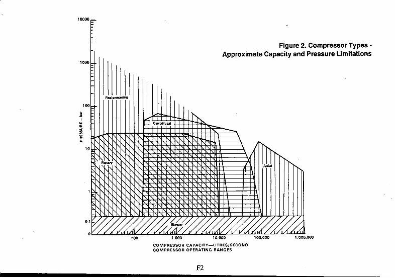
COMPRESSOR CAPACITY— LITRES/SECOND COMPRESSOR OPERATING RANGES
F2
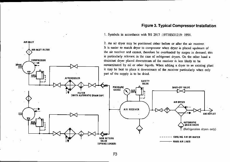
Figure 3. Typical Compressor Installation
1. Symbols in accordance with BS 2917 :1977/IS01219: 1991.
AIR INLET
I INLET FILTER
DRIVE.;
AFTERCOOLER
2. An air dryer may be positioned either before or after the air receiver.It is easier to match dryer to compressor when dryer is placed upstream of the air receiver and cannot, therefore be overloaded by surges in demand; this is particularly relevant in the case of refrigerant dryers. On the other hand a desiccant dryer placed downstream of the receiver is less likely to be contaminated by oil or other liquids. When adding a dryer to an existing plant it may be best to place it downstream of the receiver particularly when only part of the supply is to be dried.
l i FILTER(WITH AUTOMATIC DRAIN TAPI
tX H ^T non RETl
I T VALVE
AIR OUTLET
(Refrigeration dryers only)
RETURN VE
(SPRING LOADED)
COOLING AIR OR WATER
MAIN AIR LINES
F3

Figure 4. Typical Compressed Air Installation
KEY1 AIR INTAKE FILTER2 AIR COMPRESSOR3 AIR COMPRESSOR WATER TO AIR
HEAT EXCHANGER4 AIR RECEIVER5 VALVE - PRESSURE RELIEF6 ISOLATING VALVE7 MAIN LINE FILTER8 AUTOMATIC AIR RECEIVER DRAIN9 DRIP-LEG DRAIN10 DRYER11 COALESCING AFTER FILTER12 FILTER/REGULATOR13 AUTOMATIC DRABS FILTER14 LUBRICATOR15 U.H.E CARBON PACK FILTER16 PRECISION CONTROLLER17 PRIMARY FILTER18 PRECISION REGULATOR19 U.H.E. CARBON PACK FILTER
A PITCH WITH FLOW B TO MACHINE SHOP C WIDE PATTERN RETURN BENDS D TO GAUGING EQUIPMENT E DRY AIR TO PROCESS CONTROL F FILTER/LUBRICATOR UNIT G FILTER/REGULATOR AND LUBRICATOR UNIT H TO FUTURE EXTENSIONS
F4

Table 1 Air consumption of Pneumatic Equipment.Example of calculation.The following calculation is typical of a medium-sized engineering workshop including a foundry, where a high degree of mechanization is to be carried out by means of compressed air driven machines and tools.Listed in the tables are the tools and other pneumatic devices which are expected to be included in the installation at full production capacity. The use factor of the different tools is calculated in connection with production planning and thus it is possible to establish the average total air consumption.
Air Maximum AverageMachine or tool consumption Quantity air Use factor air
per unit consumption consumptionU s ANR U s ANR U s ANR
FoundryCore-shop Core blowers 11 3 33 0.50 16.5Bench rammers 5 2 10 0.20 2.0
43 18.5Machine moulding Moulding machines 12 5 60 0.30 18.0Blow guns 8 5 40 0.10 4.0Air hoist - 500kg 33 2 66 0.10 6.6
166 28.6Hand moulding Rammers
medium 6 1 6 0.20 1.2heavy 9 2 18 0.20 3.6Blow guns 8 3 24 0.10 2.4Air hoist-500 kg 33 1 33 0.10 3.3
81 10.5
Cleaning shop Chipping hammerslight 6 2 12 0.35 4.2medium 8 3 24 0.35 8.4heavy 13 2 26 0.20 5.2Grinders
75 mm 9 2 18 0.30 5.4150 mm 25 3 75 0.45 33.8200 mm 40 1 40 0.20 8.0medium 23 2 46 0.10 4.6heavySand, blast units
42 2 84 0.10 8.4
light 32 1 32 0.50 16.0heavy 53 1 53 0.50 26.5
410 , 120.5Total for foundry 700 178.1
T1 -1

Table 1. continued
Machine or toolAir
consumption per unit
L/s ANR
QuantityMaximum
airconsumption U s ANR____
Use factorAverage
airconsumption U s ANR____
WorkshopMachine shopBlow Guns 8 10 80 0.05 4.0Operatingcylinders
for jigs, fixturesand chucks 12 0.10 1.2
92 5.2Sheet metal shopDrillslight 6 1 6 0.20 1.2medium 8 1 8 0.20 1.612mm 15 2 30 0.30 9.0angle 8 1 8 0.20 1.6screw-feed 52 1 52 0.05 2.6Tapper 8 1 8 0.20 1.6Screwdrivers 8 2 16 0.10 1.6Impact Wrench20mm 15 1 15 0.20 3.022mm 23 1 23 0.10 2.3Grinders150mm 25 2 50 0.30 15.0200mm 40 1 40 0.20 8.0medium 23 2 46 0.30 13.8heavy 42 1 42 0.20 8.4Riveting hammersmedium 18 1 18 0.10 1.8heavy 22 1 22 0.05 1.1 .Chipping Hammer ilight 6 2 12 0.20 2.4medium 8 2 16 . 0.20 3.2heavy 13 1 13 0.10 1.3Air hoist - 6 tonne 33 1 33 0.05 1.7Blow guns 8 2 16 0.10 1.6
474 82.8
T l - 2

Table 2. Air Consumption of Cylinders (metric)
How to use the Nomogram opposite
1 Connect Line Pressure (A) to Stroke (B);
2 then where line (A)(B) cuts the reference line, connect across to Cylinder Bore Size (C);
3 read off consumption where this line cuts the consumption scale (D).
Figures on the left of this scale are for single-acting cylinders. Figures on the right of this scale are for double-acting cylinders, neglecting the effect of the rod.This is accurate enough for most purposes. However, if the correct (theoretical) consumption is required for double-acting cylinders, go back to the point on the reference line and connect across to the rod diameter size, entered on the ‘cylinder bore’ scale. This figure should then be deducted from the consumption arrived at with the first solution.
Example 1: Find the (nominal) consumtion of adouble-acting cylinder:
Bore = 100 mm Stroke = 180 mm Line Pressure = 8 bar A n s w e r : 25.4 litres per stroke.
Example 2: The cylinder above has a 25 mm diameter rod.Find the true (theoretical) consumption.Repeat 2 and 3 above substituting the rod diameter for the bore size.Read from the single acting cylinder side of line (D). This gives a single-acting cylinder consumption figure of 0.8 litre per stroke.Deduct this from the solution found in Example 1 to give the true consumption figure, i.e. 25.4-0.8=24.6 litres per stroke.
T 2 -1

Table 1. continued
Machine or toolAir
consumption per unit L/s ANR
QuantityMaximumairconsumption L/s ANR
Use factorAverage
airconsumtion L/s ANR
Assembly shopDrillslight 6 3 18 0.20 3.6medium 8 5 40 0.30 12.012 mm 15 6 90 0.35 31.5angle 8 2 16 0.10 1.6heavy (a) 22 1 22 0.10 2.2heavy (b) 33 1 33 0.10 3.3Tappers 8 2 16 0.10 1.6Screwdrivers 8 2 16 0.20 3.2Impact wrencheslight 6 1 6 0.20 1.220 mm 15 2 30 0.20 6.022 mm 23 1 23 0.10 2.3Grinders75 mm 9 2 18 0.20 3.6150 mm 25 1 25 0.10 2.5medium 23 2 46 0.20 9.2Air hoists500 kg 33 1 33 0.10 3.31 tonne 33 1 33 0.10 3.3Biow guns 8 5 40 0.05 2.0
505 92.4Painting shopGrinders andpoiishersangle 8 1 8 0.20 1.6medium 23 1 23 0.30 6.9Sand-blast unit 38 1 38 0.50 19.0Blow guns 8 1 8 0.10 0.8Air hoist6 tonne 33 1 33 0.05 1.7Spray painting gun 5 2 10 0.50 5.0
120 35Total for the workshop 1191 215.4See Table 2 for pneumatic cylinders.Note: To obtain equivalent compressed air flow Vc at gauge pressure P, when free air flow Vf is known, use the equation Vc = Vf x 1
P + 1
T l - 3

Table 2. Air Consumption of Cylinders (metric)
&»•*'***'—
/ » IK
/
S .3 _ .
\ --i100 § '®
- - . 5 &
- -1 . §
B ^_. soo- —
----------------- (38)*
--- I - <43»’ K
— 63
.6 0 — - > 8 0
.t o o . - - 1 0 0
< >* non^volamd
T 2 -2

Table 3 Effect of altitude on compressor capacity and power
The figures in the following table relate to machines operating at 8bar delivery pressure.
They can however also be used with reasonable accuracy for the range of discharge pressures from 5.5bar to lO.Sbar only.
Percentage reduction for each 1000 metres above sea level
Compressor type ^ Capacity - FAD Shaft Power
Screw compressor Packages 0.8 4.0Two Stage Air Cooled 2.0 7.5Two Stage Water Cooled 1.8 6.0Single Stage Single ActingAir Cooled 5.0 6.0
I j
Table 4. Pressure Drop and Flow Rate in Air Mains
How to use the Nomograms
Following the example shown in Table 4A, connect the pipe length (A) with the air flow (B) and extend to line C. The intersection on line C is then connected with the pipe diameter (D) and extended to line F. With the intersection on hne F as Pivot connect the actual working pressure (E) with scale G and read the pressure drop.
T 3 -1

TABLE 4A. Flow through Black Iron Pipes
Pipelength
(tn )
10-
20 -
100=
30o'^>.400—
1000—
1500—2000—
5000-
Freeairflow(k/S)
5000-
30002000—
1000=
500 -
\
100=
50
20— 1
Referenceline
\\
Pipe inner
diameter (mm)
Actual Ni 500—
400—
200—
180—
100—ao-jif
40—
30—
25—
20-
NeminalReference
line
Working pressure
(bar gauge)
-150
125
1^
80
65
—2
-50
40
1-32
^ 8>^10
— 15
-25
-20
Pressuredrop(bar)
— 0.03
^^0.04/
//
/
— 0.09— 0.10
- 0.20
-0.30
-oao- 1.00
-1.50
This Nomogram solves the equation dP = 1.6 X 10* X X L
X PdP = Pressure drop in bar V = Free air flow M^/s = L/s x 10'^ L = Pipe length in metres d = Inside Pipe diameter in mm P = Initial pressure in bar gauge
T4-1

Table 4B. Flow Through ABS Pipes
Pipelength
Airflow Reference
line
Compressoroutput Pressure
pressure drop(her gauge) line (bar)
’ •10—
20— ___^
30— Pipouts
B___ ide
50— diam(m
eterm j
100=^ 3000—— 2
— 2000— 0.1—200— —300— 1000—
___ Q
750— o
500— 600— 0.2—— 400— A
1000— 300— ----* *
250—200—
110— — 6 0.3—
2000— go- — 8100—
-1 00.4—
SO 7 5 -5000— S O - 63— — 12,5 0.5—
40— 0.6—
L i30— 5 0 -
0.8—r 20— ro
10— 3 2 - t s -
i. , 2.0—' 1* 5 — 25—
2.5— 20—
1.0—
16—
5tj'- '12—
T 4 -2

Table 5. Maximum recommended Flow Through Pipes and Pressure Loss Through Fittings
TABLE 5A. Maximum Recommended Flow Through Main Lines*
Nominal bore Actual bore (mm) (mm)
Rate of Air Flow at 7bar
(Litres/second)
6 6 18 9 .3
10 12 515 16 1020 22 1725 27 2532 36 5040 42 6550 53 10065 69 18080 81 240
100 105 410125 130 610150 155 900
Notes:(1) Velocity of air-flow must be restricted to less than 6 m/s as shown in Table 5A, if carry over of moisture past drain legs and excessive pressure drop is to be avoided.
(2) For pipe sizes above 150mm nominal bore, or those manufactured to standards other than BS 1387, use the formulae in Section 8.1 to calculate maximum permissible flow rate.
* Medium weight steel tube BS 1387 Table 4 or ISO 65.
T5-1

Table 5B. Maximum Recommended Flow Through Branch Lines of Steel Pipe
Maximum recommended air flow (Litres/second Free Air) (* ) through medium series steel pipe for branch mains not exceeding 15 metres length (see BS 1387).
AppliedGauge
PressureNominal Standard pipe size (Nominal Bore) - Milllimetres
6 8 10 15 20 25 32 40 50 65 80bar mm mm mm mm mm mm mm mm mm mm mm0.4 0.3 0.6 1.4 2.6 4 7 15 25 45 69 1200.63 0.4 0.9 1.9 3.5 5 10 20 30 60 90 1601.0 0.5 1.2 2.8 4.9 7 . 14 28 45 80 130 2301.6 0.8 1.7 3.8 7.1 11 20 40 60 120 185 3302.5 1.1 2.5 5.5 10.2 15 28 57 85 170 265 4704.0 1.7 3.7 8.3 15.4 23 44 89 135 260 410 7256.3 2.5 5.7 12.6 23.4 35 65 133 200 390 620 10858.0 3.1 7.1 15.8 29.3 44 83 168 255 490 780 137510.0 3.9 8.8 19.5 36.2. 54 102 208 315 605 965 169512.5 4.8, 10.9 24.1 44.8 67 127 258 390 755 1195 211016.0 6.1 13.8 30.6 56.8 85 160 327 495 955 1515 266520.0 7.6 17.1 38.0 70.6 105 199 406 615 1185 1880 3315
General Notes: • The flow values are based on Maximum Recommended Peak Flows. Normal steady state air consumption should not exceed 80% of these figures in pipe sizes 6 mm-15 mm Nominal Bore and 60% of these figures in pipe sizes 20 mm Nominal Bore and above.
♦* Applied pressure selected from ISO 2944: Fluid Power Systems-nominal pressures.
T 5 -2

Table 5C. Pressure Loss Through Steel Fittings-Equivalent Pipe Lengths.
ItemEquivalent pipe length in metres
15Inner pipe
20 25diameter 40 50
in mm 80 100 125 150 200
Gate Valvefully open 0.1 0.2 0.3 0.5 0.6 1.0 1.3 1.6 1.9 2.6half closed 3.2 5 8 10 16 20 25 30 40
Diaphragm Valvefully open 0.6 1.0 1.5 2.5 3.0 4.5 6 8 10
Angle Valve fully open 1.5 2.6 4 6 7 12 13 18 22 30
Globe valve fully open 2.7 4.8 7.5 12 15 24 30 38 45 60
Ball valve (full bore) 0.5 0.2 0.2 0.4 0.3 0.4 0.3 0.5 0.6 0.6fully open
Ball valve (reduced bore) 3.4 4.9 2.4 2.2 5.0 2.6 4.1 3.3 12.1 22.3fully open
Swing check valve fully open 1.3 2.0 3.2 4.0 6.4 8.0 10 12 16
Bend R = 2d 0.1 0.2 0.3 0.5 0.6 1.0 1.2 1.5 1.8 2.4Bend R = d 0.2 0.3 0.4 0.6 0.8 1.3 1.6 2.0 2.4 3.2Mitre bend 90° 0.6 1.0 1.5 2.4 3.0 4.8 6.0 7.5 9 12Run of tee 0.2 0.3 0.5 0.8 1.0 1.6 2.0 2.5 3 4Side outlet tee 0.6 1.0 1.5 2.4 3.0 4.8 6.0 7.5 9 12Reducer 0.3 0.5 0.7 1.0 2.0 2.5 3.1 3.6 4.8
Note: the table shows the type of fitting.
length of pipe with equivalent pressure loss in a given size and
T 5 -3

Table 5D. Pressure Loss Through ABS Fittings-Equivalent Pipe Lengths
Pipe outside 16 20 25 32 40 50 63 75 90 110diameter-mm Equivalent pipe length in metres
90°elbow 1.96 1.26 1.22 1.15 1.11 1.07 1.08 1.09 1.10 1.11
45° elbow 1.26 0.90 0.68 0.46 0.45 0.43 0.40 0.48 0.57 0.69
90° bend 0.85 0.61 0.59 0.49 0.47 0.44 0.42 0.43 0.51 0.59
Tee in line 0.87 0.38 0.26 0.29 0.28 0.29 0.23 0.11 0.10 0.15flowTee in line to branch flow
2.45 1.95 1.52 1.44 1.32 1.18 1.06 1.10 1.19 1.32
Reducer 2.04 1.42 1.35 1.29 1.27 1.25 1.28 1.33 1.39 1.45
180°dropped 0.36 0.39 0.37 0.36bendComposite 0.91 0.47 0.41 0.36 0.34 0.31 0.28unionsNote: The table shows the length of pipe with equivalent pressure loss in a given size and type of fitting. For example £ 50 min/90° elbow has a pressure loss equal to 1.07 metres of 50mm ABS pipe.
Table 5E. Recommended Flow Rates - ABS pipe
Applied pressure (bar) 0.5 1.0 2.0 4.0 6.0 8.0 10.0 12.5Pipe size Maximum recommended air flow - L/sec
16mm 0.9 2 4 8 12 18 21 2620mm 1 2 5 10 16 23 28 3825mm 2 4 11 19 31 43 54 7132mm 4 9 23 42 63 82 107 13440mm 8 19 43 85 120 160 195 24550mm 13 27 65 122 194 261 337 44063mm 25 50 119 229 366 492 646 80575mm 36 80 201 360 565 791 975 127590mm 60 135 309 570 885 1271 1525 2042110mm 105 225 521 1000 1570 2210 2710 3444Note: Examples of maximum recommended air flow rates for various sizes of ABS pipe and air pressures are given in the tables above. These £U"e based on pressure drops per 30m (100ft), of pipe using 10% of applied pressure for 16mm size and 5% for all other sizes
T 5 -4

Table 6 Typical Standard Air Receivers
Nominal Capacity Litres
lypical Shell Length Metres
Receiver Shell Diameter Metres
200 1.22 0.46350 1.52 0.51500 1.52 0.61900 1.68 0.761200 1.68 0.911800 2.59 0.912000 1.98 1.072800 2.13 1.223500 2.74 1.22
Shell length is that of cylindrical shell only and excludes the dished ends. An approximation to the overall length of the shell can be obtained by increasing the length stated by 10% for each convex dished end.
T 6 -1

H
Water Vapour Content and resulting Pressure Dewpoint Temperature °C at various gauge pressures (bar) Note:Table 7 was compiled from information kindly provided by British Aerospace (Dynamics) Ltd. - Stevenage. The original data was in the form of a graph covering 26 pressure ranges from 0. Ibar absolute to 500 bar gauge and temperatures from -80°C to+50°C. This was reproduced on A1 size paper and any attempt to reduce this to A5 size would render it unintelligible. A full size copy is in the BCAS archives.
Water Vapour Content 0 bar Pressure bar gaugeat atmospheric pressure 1013mbar/lS°(
atmospheric 6.3 10 16 25 40 63 100 250 400
mg/m1 -74 -63 -60 -57 -53 -51, -48 -47 -45 -432 -70 -59 -55 -53 A9 -46 -43 -42 -39 -38
4 -65 -53 -50 -47 -43 -40 -36 -34 -31 -296 -63 -50 -46 -43 -39 -36 -33 -30 -26 -24
10 -59 ^5 A2 -39 -34 -30 -27 -24 -20 -17
20 -54 -39 -35 -31 -26 -23 -19 -16 -11 -740 -48 -32 -27 -24 -19 -15 -10 -7 -1 +360 -45 -28 -24 -20 -15 -11 -7 -2 +5 +9
100 -40 -22 -18 -14 -9 -5 +0 -1-5 +12 + 11200 -34 -15 -10 -6 -1 +4 -t-11 -1-16 +24 +29400 -27 -7 -2 -1-3 -t-9 -1-15 -1-22 -t-28 +31 +42600 -23 -2 +4 -1-9 -H5 +22 -h29 -1-36 -t45
g/m®1 -18 +5 -t-ii -t-16 -t-24 +30 - 38 -i462 -11 -1-15 -1-22 +21 -1-34 +42 -1-504 -2 -1-26 +34 -f40 -1-50 16 +3 -1-34 +42 -t48 ABOVE
10 +10 +44 -t-50 50”C
2
>
i-toa .3&95?
v></)ea
o3'S'

Table 8. Leakage Loss In Compressed Air Systems
The following table shows the volume of air (at 7 bar) lost through leakage, together with the resultant approximate power required to maintain such a leakage.The figures are based on a flow coefficient of 0.65 for non circular shapes.
Equivalent Hole diameter
mm
Air leakage at 7 bar
L/s
♦Power required by the compressor
kW0.5 0.2 0.061.0 0.8 0.241.5 1.8 0.542.0 3.1 0.936.0 28.2 8.5
10 78.1 23.4
* Based on 300W/L/s
T 8 -1

9 A Steel
Intervals Between Pipe Supports
PinePipe size Maximum intervals Maximum intervalsNom. bore for vertical runs for horizontal runsmm m m
8 1.25 1.010 1.25 1.015 1.75 1.2520 2.50 1.7525 2.70 1.7532 3.00 2.5040 3.00 2.5050 3.00 2.7565 3.50 3.00
100 3.50 3.00150 4.25 3.50200 4.50 3.50250 5.18 4.25300 5.48 4.87
over 300 5.48 4.87
9 B ABS Pipe** 9 C Copper Pipe*PipeOutsidediametermm
Support Spacing
at 20“C m
16 1.120 1.225 1.432 1.540 1.750 1.963 2.175 2.390 2.5no 2.8
PipeOutsidediameter
mm
Maximum intervals
for vertical runsm
Maximumintervals
for horizontal runsm
12 1.2 1.015 1.8 1.222 2.4 1.828 2.4 1.835 3.0 2.442 3.0 2.454 3.0 2.776 3.6 3.0
* Information extracted from Hospital technical Manual.
♦•For each 10° C temperature rise reduce support spacing by 10% These support centres can be increased by 50% for vertical pipes.
T9-1

Table 10. Flow In Tubes And Hoses
Table lOA.Maximum Recommended Air Flow (Litres/second)* Through Copper or Nylon Tubing and Corresponding Port Thread (ISO 1179)
Appliedgaugepressure
Nominal Ibbing Size (Outside diameter)-Millimetres
* *
bar4Gl/16
5Gl/8
6Gl/8
8G l/4
10 12G l/4 G3/8
16G l/2
18G l/2
22G3/4
28G1
1.6 0.05 0.12 0.19 0.48 0.9 1.8 4.2 6.5 10.0 18.02.5 0.08 0.18 0.26 0.70 1.3 2.8 7.2 8.8 14.0 30.04.0 0.14 0.28 0.45 1.2 2.2 4.5 12.0 15.0 24.0 50.06.3 0.22 0.48 0.72 2.0 3.8 7.6 20.0 25.0 40.0 80.08.0 0.28 0.62 0.95 2.6 4.8 9.5 26.0 31.0 52.0 110.010.0 0.36 0.81 1.3 3.5 6.2 12.0 34.0 41.0 68.0 140.012.5 0.46 1.1 1.7 4.3 8.0 17.0 44.0 53.0 85.0 180.0
Notes: The flow rates are selected to provide an approximate pressure drop with either nylon or copper tubing as follows:
7.5% of applied pressure per 15 metres of tubing in sizes 4 mm to 16 mm inclusive.
5% of applied pressure per 15 metres of tubing in sizes 18 mm to 28 mm inclusive.
* Free Air flow
♦♦Applied pressure selected from ISO 2944 ‘Fluid Power Systems-Nominal Pressures’.
T lO -1

Table lOB. Typical Pressure Loss in Smooth-Bore Hose
(Including Pressure Drop Across Standard Fittings at Each End) rX
\ '
Nominal Bore of Hose BS 5118 mm
GaugePressure Air Flow in Litres/second through 15 metres of hose at hose 10 16 25 40 60 80 100
bar Pressure loss in bar per 15 m length
12.5 4 0.1 0.3 1.06 0.06 0.2 0.7 2.1
19 4 0.02 0.04 0.2 0.4 1.06 0.01 0.03 0.1 0.2 0.5
25 4 0.01 0.03 0.1 0.3 0.6 1.06 0.01 0.02 0.05 0.1 0.2 0.3
31.5 4 0.01 0.02 0.07 0.1 0.26 0.01 0.04 0.06 0.07
38 4 0.01 0.02 0.04 0.076 0.01 0.02 0.03
T lO -2

Table 11. Air Flow Through Nozzles
NozzleDiameter
Litres Per Second - ANR
mm 2 bar 3 bar 4 bar 5 bar 6 bar 7 bar0.1 0.004 0.006 0.008 0.009 0.011 0.0120.2 0.018 0.024 0.032 0.036 0.044 0.0480.3 0.041 0.054 0.063 0.0811 0.095 0.1080.5 0.114 0.151 0.188 , 0.225 0.263 0.3001.0 0.453 0.603 0.733 0.901 1.051 1.2011.5 1.021 1.358 1.699 2.033 2.366 2.6892.0 1.815 2.416 3.016 3.615 4.198 4.7983.0 4.082 5.431 6.764 8.113 9.463 10.8124.0 7.264 9.646 12.045 14.411 16.823 19.1595.0 11.346 15.077 18.826 22.49 26.32 29.996.0 16.34 21.72 27.16 32.49 37.82 43.328.0 29.16 38.65 48.15 57.6 67.3 76.9
10.0 43.32 60.3 75.3 90.1 105.1 120'.112.0 65.3 86.9 108.3 129.6 151.4 173.315.0 102.1 135.8 169.9 203.3 236.6 269.920.0 181.6 241.6 301.5 361.5 419.8 479.825.0 283.2 376.5 469.8 563.1 658.0 749.730.0 408.2 543.1 676.4 811.3 946.3 108135.0 556.4 739.7 921.3 1104 1287 147140.0 726.4 964.6 1204 1441 1682 191545.0 919.6 1221 1521 1832 2132 243250.0 1134 1507 1882 224955.0 1372 1824 226560.0 1634 2172
See page T ll-2 for Notes and gauge pressures 8bar and above.
T il -1

Table 11. Air Flow Through Nozzles - continued
NozzleDiameter
Litres Per Second - ANR
mm 8bar lObar 12bar ISbar 20bar 30bar0.1 0.014 0.017 0.020 0.024 0.031 0.0470.2 0.056 0.068 0.080 0.096 0.124 0.1880.3 0.122 0.148 0.175 0.217 . 0.283 0.4180.5 0.388 0.413 0.487 0.600 0.786 , 1.1601.0 1.351 1.649 2.949 2.399 / 3.132 4.6481.5 3.049 3.715 4.382 5.381 7.080 10.4462.0 5.398 6.597 7.797 9.580 18.578 18.4933.0 12.162 14.844 17.493 21.66 28.32 41.824.0 21.66 26.41 31.15 38.32 50.3 74.15.0 33.82 41.32 48.81 59.9 78.6 115.96.0 48.65 59.5 70.3 86.3 113.3 166.68.0 86.5 105.6 124.9 153.3 201.6 296.5
10.0 135.1 164.9 194.9 239.9 313.2 464.812.0 194.6 238.2 281.6 344.8 453.2 668.115.0 304.0 371.5 438.2 538.1 708.1 104420.0 539.8 659.7 779.7 959.9 1257 184925.0 844.7 1031 1217 1499 196630.0 1216 1484 1749 216535.0 1654 2015 239940.0 2165 2648
Notes:1. The above data is based on 100% flow coefficient for a well rounded nozzle entrance; muliply these values by 0.96 where nozzles have sharp edged entry.2 Values should be multiplied by 0.65 for approximate results with non-circular shapes3. ANR indicates Free Air Flow (See 2.20)4. Pressure (bar) is gauge pressure.
T i l - 2

Table 12 International Standards (ISO).
This table is based on the ‘1992’ ISO Catalogue, updated where more recent changes are known.
The column ‘Corresponding BS’ is based on the ‘BSI Catalogue 1992’ (up dated where known), using the symbols for ‘varying degrees of agreement’ listed there, i.e:
= an identical standard: a national standard identical in every detail with a corresponding international standard or standards; published with dual numbering.
— a technically equivalent standard: a national standard in all technical respects the same as corresponding international standard or standards; the wording and presentation may differ quite extensively.
9^ a related standard: a national standard, the content of which, to any extent at all short of complete identity or technical equivalence, covers subject matter similar to that covered by a corresponding international standard or standards. It is emphasised that whilst the subject matter is similar the standard may deal with it in a different manner.
This Table is based on the ISO Technical Committees (TCs) who issued the Standard and follow the numerical order of the TCs.
ISONumber TiUe Corresponding BS.
TCS
IS07-1:1982
Ferrous Metal Pipes and metallic fittings.
Pipe threads where pressure tight joints are made on the threads - Part 1: Designation, dimensions and tolerances = 21
IS07-2:1982 Pipe threads where pressure tight joints are made on the threads - Part 2: Verification by means of -limit gauges ^ 21
T12 -1 ■

ISONumber Title Corresponding BS.
18013:1978
18049:1983.
Grey iron pipes, special castings and grey iron parts for pressure main lines
Malleable cast iron fittings threaded to 1807-1
^ 4622
^ 1211, 143&1256
18050:1970
18065:1981
Withdrawn in 1986 and not replaced.
Carbon steel tubes suitable for screwing in accordance with 180 7-1 = 1387
180221:1976.
180228-1:1982
Withdrawn in 1986 and not replaced.
Pipe threads where pressure tight joints are not made on the threads - Part 1: Designation, dimensions
and tolerances = 2779
180228-2:1987 Pipe threads where pressure tight Joints are not made on the threads - Part 2: Verification by means of limit
gauges — 2779
180559:1991
1801179:1981
Welded or seamless tubes for water and sewage.
Pipe connections threaded to 180 228-1, 4368 Pts. 1 &3for plain end steel and other metal tubes and 5380 in industrial applications
180 2016:1981 Capillary solder fittings for copper tubes - Assembly, dimensions and tests 5^ 864 Pt. 2
1802084:1984 Withdrawn in 1988. SMlS07005-2and 1807005-3.
1802441:1975 Withdrawn in 1988.See 1807005-2 and 1807005-3.
T12-2

ISONumber Title Corresponding BS.
1802531:1991
1803419:1981
1803545-1:1989
1803545-3:1989
1804144:1979
1804145-1986
1804200:1991
1805251:1981
1806708:1980
1806761:1981
1807005-2:1988
1807005-3:1988
180 7268:1983
1807598:1988
Ductile iron pipes, fittings and accessoriesfor pressure pipelines ^ 4772
Non-alloy and alloy steel butt-welding fittings
8teel tubes and fittings - 8ymbols for use in specifications Part 1: Tubes and tubular accessories
with circular cross-section.
Part 3: Tubular fittings with circular cross-section.
8tainless steel fittings threaded to 1807-1.
Non alloy steel fittings threadedto 180 7-1 1740 Pt.l
Plain end steel tubes, welded andseamless-General tables of dimensionsand masses per unit length. = 3600
Stainless steel butt welding fittings.
Pipe components definition of nominal size.
Steel tubes - Preparation of ends of tubes and fittings for welding.
Metallic flanges.- Part 2 Cast iron flanges. ^ 1560 & 4504
Copper alloy and composite flanges. ^ 1560 & 4504
Pipe components - Definition of nominal pressure.
Stainless steel tubes for screwing in accordance with 1807-1.
= 6362
T 1 2 - 3

ISONumber
1809095:1990
TC8
ISOR508:1966
ISOR538:1967
1803948:1977
TC12
1801000:1981
TC17
,1802604-2:1975
1802604-3:1975
s
Title Corresponding BS.
8teel tubes - Continuous character markings colour coding for material identification.
Ship building and Marine Structures
Withdrawn in 1986 and not replaced.
Conventional signs to be used in schemes for pipeline systems in ships.
Shipbuilding - inland vessels- compressed air systems
- Pressure ranges.
Quantities, units, symbols, conversion factors and coversion tables.
81 units and recommendations for the use of their multiples and of certain other units.
Steel (for pressure purposes)
8teel products for pressure purposesQuality requirementsPart n:Wrought seamless tubes.
8teel products for pressure purposes Qudity requirements Part ni:Electric resistance and induction-welded tubes.
T12-4
= 5555:1987
^ 3601,3602, 3604, 3606.
^ 3601,3602, 3604, 3606.

ISONumber Title Corresponding BS
1802604-4:1975. Steel products for pressure purposes Quality requirements PartrV:Plates Withdrawn: See 9328-1.
1802604-6:1978 Steel products for pressure purposes Quality requirements Part VI: Submerged arc longitudinally or spirally welded steel tubes. 3601,3602.
1803755:1976 Cast steels for general engineering purposes
1806303:1981
ISO 9328-1:1991
Pressure vessel steels not included in ISO 2604, Parts 1 to 6 Derivation of long time stress rupture properties
Steel plates and strip for pressure purposes -Technical delivery conditions - Part 1 General requirements.
1809329-1:1989 Seamless steel tubes for pressure purposes;Technical delivery conditions:Part 1. Unalloyed steel tubes with specified room temperature conditions.
1809330-1:1990 Welded steel tubes for pressure purposes;Technical delivery conditions:Part 1 unalloyed steel tubes with specified room temperature conditions.
TC19
1803:1973
Preferred Numbers
Preferred numbers Series of preferred numbers. = 2045
T 1 2 -5

ISONumber Title Corresponding BS
18017:1973 Guide to the use of preferred numbers and of series of preferred numbers. = 2045
180497:1973 Guide to the choice of series of preferred numbers. = 2045
TC20
1802434:1973
Aircraft and space vehicles
Compressed non-breathing air for use in aircraft.
1802533:1975 Standard Atmosphere [ 1013 mbar, 15°C, absolutely dry ]
TC26
180274:1975
Copper and copper alloys
Copper tubes of circular section Dimensions.
1801635:1974 Round tubes for general purposes. Mechanical properties.
TC28
1803448-1975
Petroleum products and lubricants
Industrial liquid lubricants 180 viscosity classification.
= 4231
1805024:1976 Petroleum liquids and gases Measurement8tandard reference conditions.
^ 5579
1806743-3A:1987 Lubricants, industrial oils and related products (Class L) Clpsification Part 3A:Family D (Compressors).
= 64138ection 3.1.
T 1 2 -6

ISONumber TiUe Corresponding BS
IS06743-3B:1988
1806743-11:1990
Part 3B:Family D (Gas Compressors).
Part 11Family P (Pneumatic Tools).
= 6413 Section 3.2.
TC29
1801180:1983
1802284:1987
1804230:1987
1804231:1987
1805969:1979
Small Tools
Shanks for pneumatic tools and fitting dimensions for chuck bushings.
Hands taps for parallel and taper pipe threads - General dimensions and marking.
Hand and machine operated circular screwing dies for taper pipe threads - R series.
Hand and machine operated circular screwing dies for parallel pipe threads - G series.
Ground thread taps for pipe threads G series and Rp series Tolerances on the threaded portion. Technical Addendum issued 1991.
673:1984, plus Addendum
= 949 Part 3.
= 1127 Part 2.
= 1127 Part 3.
— 949 Part 3.
TC39
I80R369:1964
1805169:1977
Machine Tools
♦Symbols for indications appearing on machine tools.
^ 3641
^ 5739
♦ Some of these symbols are used on compressed air equipment
♦Machine tools presentation of lubrication instructions
T 1 2 - 7

ISONumber Title Corresponding BS
TC43
1804872:1978
Acoustics
Acoustics - Measurement of airborne noise emitted by construction equipment intended for outdoor lise Method of checking compliance with noise limits. .
TC45
1801307:1983
1802398:1987
1803861:1977
1805774:1980
1807233:1983
1807751:1991
1808028:1987
180 8331:1991
Rubber and rubber products and plastics
Rubber and plastic hoses boresizes and tolerances on length. = 6597
Industrial rubber hose for compressed air(up to 25bar).
Rubber hose for grit blasting.
Plastic hosesTextile reinforced thermoplastics type for compressed air 8pecification.
Rubber and plastic hoses and hose assemblies Vacuum resistance Methods of test.
Rubber and plastic hoses and hose assembliesRatios of proof and burst pressure to design working pressure.
Rubber and/or plastic hoses for airless paint spraying - 8pecification.
Rubber and plastic hose assemblies Guide to selection, storage, use and maintenance.
= 5118
^ 5121
= 6066:1981
= 51738ection 102.9
= 6596.
T12-8W
. , J

ISONumber Title Corresponding BS
TC108
ISO 2631-1:1985
ISO 2631-3:1985
ISO 5349:1986
Mechanical vibration and shock
Evaluation of human exposure to wholebody vibration.Part 1 - General requirements.
Part 3 - Evaluation of exposure to Z-axis vertical vibration.
Mechanical vibration Guide-lines for the measurement of human exposure to hand transmitted vibration.
^ 6841
^ 6842
TC112
IS01607-1:1980
ISO1607-2:1989
ISO1608-1:1980
ISO 1608-2:1989
Vacuum Technolgy
Positive displacement vacuum pumps Measurement of performance characteristicsPart 1: Measurement of volume rate of flow (pumping speed)
Positive displacement vacuum pumps Measurement of performance characteristicsPart 2: Measurement of ultimate pressure
Vapour vacuum pumps Measurement of performance characteristicsPart 1: Measurement of volume rate of flow (pumping speed)
Vapour vacuum pumps Measurement of performance characteristicsPart 2: Measurement of critical backing pressure
T12-9

ISONumber
1801609:1986
1802861-1:1974
1802861-2:1980
1803529-1:1981
1803529-2:1981
1803529-3:1981
1803530:1979
1803669:1986
1803753:1977
TC118
1801217:1986
Title
Flange dimensions.
Vacuum technology Quick release couplings Dimensions, Part 1: Clamped type
Vacuum technology Quick release couplings Dimensions, Part 2: 8crewed type
Vacuum technologyVocabularyPart 1, General termsTrilingual edition
Vacuum technology VocabularyPart 2: Vacuum pumps and related terms Trilingual edition
Vacuum technology VocabularyPart 3: Vacuum gauges Trilingual edition
Vacuum technology Mass-spectrometer-type leak-detector calibration.
Bakable flanges - Dimensions.
Graphical 8ymbols.
Compressors, pneumatic tools and pneumatic machines
Displacement compressors Acceptance Tests.
T12 -10
Corresponding BS
= 5914:1980
= 5543.
= 1571:1987

ISONumber Title Corresponding BS
1802151:1972 Measurement of airborne noiseemitted by compressors/primemover-units intended for outdoor use(To be replaced by future IS03989 of TC43).
1802787:1984 Rotary and percussive pneumatic tools Performance tests. = 5344
1803857-1:1977 Compressors, pneumatic tools and machinesVocabulary - Part 1: General Bilingual edition = 5791:Pt. 1:1979
1803857-2:1977 Compressors, pneumatic tools and machinesVocabulary - Part 2: Compressors Bilingual edition. = 5791:Pt. 2:1979
1803857-3:1989 Compressors, pneumatic tools and machinesVocabulary - Part 3: pneumatic tools and machines Bilingual edition. = 5791:Pt.3:1984
1805388:1981 8tationary air compressors 8afety rules and code of practice. = 6244:1982
180 5389:1992 Turbo Compressors -Performance Test Code.
1805390:1977 Compressors Classification Bilingual edition
1805391:1988 Pneumatic tools and machines Vocabulary.
1805393:1981 Rotary pneumatic assembly tools for threaded fasteners Performance Tests. = 6292:1982
T12-11

ISONumber
1805941:1979
1806544:1981
1807183:1986
1808010:1988
1808011:1988
1808012:1988
1808573-1:1991
1808662-1:1988
TC119
1804003:1977
Title Corresponding BS
Compressors, pneumatic tools and machines Preferred pressures
Hand held pneumatic assembly tools for installing threaded fasteners Reaction torque and torque impulse measurements.
Compressed air dryers 8pecification kid testing.
Process Compressors 8crew and related types Design and construction.
Process compressors Turbo types8pecification for design and construction.
Process compressors Reciprocating types 8pecification for design andconstruction.
Compressed air for general usePart 1: Contaminants and quality classes.
Hand held power tools: Measurement of vibration at the handle Part 1: General.
Powder Metallurgy
Permeable sintered metal materials Determination of bubble test pore size.
= 6268:1982
= 6754
= 7316:1990
= 7321:1990
= 7322:1990
= 5600:8ection 3.5 1987
•T12 - 12

ISONumber Title Corresponding BS
TC131
ISO 1219-1:1991
Fluid Power Systems
Fluid Power Systems and components Graphic symbols and circuit diagrams Part 1 - Graphic symbols. = 2917 Part 1.
ISO 2944:1974 Fluid Power Systems and components Nominal pressures
ISO 3320:1987 Fluid Power Systems and components Cylinder bores and piston rod diameters Metric series. = 5755
ISO 3322:1985 Fluid Power Systems and components Cylinders: Nominal pressures 5755
ISO 3601-1:1988* Fluid Systems: O ringsPart 1: Inside diameters, cross sections,tolerances and size identification code
ISO 3601-3:1987 Fluid Systems: Sealing devices: O ringsPart 3 Quality acceptance criteria. ^ 6442
ISO 4393:1978 Fluid Power Systems and components Cylinders:Basic series of piston strokes. = 5755
ISO4394-l:1980 Fluid Power Systems and components Cylinder barrels:Part 1: Requirements for steel tubes with specially finished bores. ^ 5242 Pt. 1
IS04395:1978 Fluid Power Systems and components Cylinders: Piston rod thread dimensions and types. = 5755
IS04397:1978 Fluid Power Systems and componentsConnectors and associated components Outside diameters of tubes and inside diameters of hoses.
*Many UK manufacturers of compressed air equipment fit O-rings made to the genuine metric standard BS 4518
T12 -13

ISONumber Title Corresponding BS
1804399:1977 Fluid Power Systems and components Connectors and associated components Nominal pressures
1804400:1985 Fluid Power Systems and components Three pin electrical plug connector Characteristics and requirements. = 6361
1804414:1982 Fluid Power Systems and components Recommendations for the application of equipment to transmission and control systems. ^ 4575 Pt. 2
ISO 5598:1985 Fluid power systems and components Vocabulary - Bilingual edition (currently under revision).
ISO 5599-1:1989 Five port directional control valves Part 1 Mounting interface surfaces without electrical connector. = 7389 Pt.l
1805599-2:1990 Five port directional control valves Part 2: Mounting interface surfaces with optional electrical connector.
1805599-3:1990 Five port directional control valves Part 3 Code system for communication of valve functions.
ISO 5782:1990 Compressed air filtersPart 1 Main characteristics to beincluded in commercial literature.
1806099:1985 Fluid power systems and components Cylinders - Identification code for mounting dimensions and mounting types.. ^ 6331
1806149:1980* Fluid power systems and components Metric ports : Dimensions and design.
* The European pneumatic industry uses ports to ISO 1179 with threads to ISO 7 or ISO 228 (ail TC 5)
T12 -14

ISONumber
1806150:1988
Title Corresponding BS
Cylinder quick action couplings for maximum working pressures of 10, 16 and 25bar. Plug connecting dimensions, specifications and testing.
1806301-1:1989 Compressed air lubricators Part 1: Main characteristics to be included in commercial literature.
1806358:1989 Components using compressible fluids. Determination of flow rate characteristics. = 7294
1806430:1983 8ingle rod cylinders with integral mountings lObar series Bores from 32 to 320mm Mounting dimensions.
1806431:1981 Pneumatic fluid power: 8ingle rod cylinders with detachable mountings Bores from 32 to 320mm Mounting dimensions. = 4862 Pt 2
1806432:1985 8ingle rod cylinders lObar series. Bores from 8 to 25mm Mounting dimensions. 4862 Pt 1
1806537:1982 Pneumatic fluid power systems Cylinder barrels Requirements for non-ferrous metallic tubes. = 5242: Pt 2: 1983
1806952:1989 Two pin electrical plug connector with earth contact Characteristics and requirements.
1806953-1:1990 Air line pressure regulators Part 1: Main characteristics to be included in commercial literature.
1807180:1986 Pneumatic cylinders Bore and port thread sizes.
T12 - 15

ISONumber Title Corresponding BS
1808139:1991
1808140:1991
1808778:1990
IS010099;1990
Pneumatic cylinderslObar series - Rod end spherical eyesMounting dimensions.
Pneumatic cylinders lObar series - Rod end clevis Mounting dimensions.
8tandard reference atmosphere:Ibar absolute20°C - 65% relative humidity.
Pneumatic cylinders - Acceptance test.
TC138
180161-1:1978
I80/TR 6285:1980
Plastic pipes, fittings and valves
Thermoplastic pipesnominal outside diameters andnominal pressures. Part 1 metric series. ^ 5556
AB8 pipes and fittingsChemical resistance with respect to fluids.
TC145
180 3461-1:1988
180 3461-2:1987
180 3864:1964
1807000:1989
Graphical symbols
General principles for the creationof graphical symbolsPart 1 - 8ymbols for use on equipment.
Part 2 - 8ymbols for use in technical product documentation.
8afety colours and safety signs.
Graphical symbols for use on equipment - Index and synopsis.
^ 5378
= 7324.
T12-16

ISONumber Title Corresponding BS
TC153 Valves
1804126:1981 8afety valves - General requirements. ^ 1123,6759.
1805208:1982 Industrial valves - pressure testing. ^ 6755 Pt.l
1805209:1977 Industrial valves - marking. = 5418
1807121:1986 Flanged steel ball valves. ^ 5159
TC154 Documents and data elements
180 3166:1988 Codes for representation of names of countries. = 5374
1808601:1988 Representation of dates and times. = 7151
TC176 Quality management and quality assurance
1808402:1986 Quality vocabulary - Trilingual edition. = 4778 Pt. 1.
1809000:1987 Quality management and quality assurance standards Guidelines for selection and use.
= 5750 Part 0 8ection 0.1.
1809001:1987 Quality systems - design, development production, installation and servicing. = 5750 P t.l
1809002:1987 Quality systems - Production and . installation. = 5750 Pt. 2
1809003:1987 Quality systems - Final inspection and test. = 5750 Pt. 3
1809004:1987 Quality management and quality Systems Guidelines.
= 5750 Part 0 8ection 0.2.
T12 -1 7

ISONumber Title Corresponding BS
18010011-1:1990
ISO 10011-3:1991
TC185
1804126-1:1991
180 6718:1991
Guidelines for auditing qualitysystems: Part 1 Auditing. = 7229 Parti.
Part 3 Management of audit programmes. = 7229 Part 3.
Safety devices for protection against excessive pressure.
Safety valvesPart 1 - General requirements
Bursting discs and bursting disc devices.
^ 1123,6759
^ 2915.
TC199 Safety of machinery
No standards yet issued.
T12-18

Table 13. British StandardsThe data in this table are reproduced from BSI Catalogue 1992 (the position at 29 February 1992 and updated to 30 June 1992) where more information is available. Not all ISO publications referred to in Table 13 will be found in Table 12.See also ‘Concluding Note’ at the end of this table.
The Table 13 is divided into subject headings:A. Pipes, tubes, hoses, pressure vessels and valves;B. Protective equipment and precautions;C. Filters, dryers and lubricators;D. Compressors, vacuum plant and pneumatic tools;E. Pneumatic control equipment;F. Symbols, units, tables and data presentation.
Note: Dates in brackets indicate a standard originally issued at an earlier date but subsequently confirmed unchanged. The new printing however includes all amendments.
BS Number Description Remarks
Pipes-Tubes-Hoses-PressureVessels-Vaives
BS21:1985Pipe threads for tubes and fittings where pressure tight joints are made on the threads.A range of jointing threads , size 1/16 to 6, where pressure tight joints are made by mating taper internal and external threads or taper external and parallel internal threads.
Basis for the compressed air industry’s preferred method of connecting/sealing: tapered male connector into parallel pipe threaded port. (While the 1/16 size was originated by pneumatic interests, it has found little use. Makers of miniature pneumatic cylinders prefer M5 ports.)= IS07- 1. ^ IS07- 2
f’lBS143& 1256: 1986 Malleable cast iron and cast copper
alloy, screwed pipe fittings BS143 having taper internal and external threads. BS1256 having taper external and parallel internal threads. ^ IS049.
BS470:1984Specifications for inspection, access and entry openings for pressure vessels.
T13-1

Table 13. continuedBS Number Description Remarks
BS864 Capillary and compression tubefittings of copper and copper alloy.
BS864: Part 2 1983Specification for capillary and compression fittings for copper tubes.
BS949 Part 3:1982
BS1101:1977
Specifications for taps for pipe threads to BS21 and BS2779(G,Rp and Rc) series.
^ ISO2016.
= IS02284. = IS05969.
Specifications for pressure containers Includes cast aluminium containers, for paint and other substances. Lessthan 840mm inner diameter and below receivers where EN286 is not lObar design pressure.
BS1127
Part 2 1990
Part 3 1990
BS 1256:1968
BS 1306: (1990)
BS1387:(1990)
Specification for hand and machine operated screwing dies.
Taper pipe threads:BS21.R Series.
Parallel pipe threads:BS2779 G Series.
WITH DRAWN
Specification for copper and copper alloy pressure piping systems including compressed air for industrial and marine use.
Steel tubes and tubulars suitable for screwing to BS21 pipe threads.
Could be relevant to small air receivers wl applicable.
Consists of 5 Parts.
= ISO4230and EN24230.
= IS04231 and EN24231.
See BS 143.
BS5222 covered aluminium but has been withdrawn.
= IS065.
T 1 3 - 2

Table 13. continuedBS Number Description Remarks
BS1471:1972*
BS 1474:1987*
Specification for wrought aluminium and aluminium alloys for general engineering purposes - drawn tube.
Specification for wrought aluminium and aluminium alloys for general engineering purposes - extruded round tubes and sections.
BS1501:Pt 1:(1990)Specification for carbon and carbon manganese steels. Composition and acceptance properties for range of steel plates intended for pressure purposes.
^ ISO209-1 and ISO209-2.
IS06362 Relevant to ♦Aluminium piping systems. -
1502604- 1 and1502605- 1.
BS1501 Pt 2:1988
BS1502:(1990)
Alloy steel plates for pressure purposes.
Specification for steels for fired and unfired pressure vessels: sections and bars: General and testing requirements for carbon, carbon-manganese low and medium alloy, austenitic steel sections and bars for fired and unfired pressure vessels.
^ ISO2604-4.
BS 1503:1989Specification for steel forgings (including semi finished forged products) for pressure purposes. Specifies the requirements for carbon-manganese, low alloy ferritic steel, martensitic and austenitic stainless steel forgings for pressure purposes. ^ ISO2604-1.
T 1 3 - 3

Table 13. continuedBS Number Description Remarks
BS1504:1984
BS 1506:1990
BS1515
BS1560
Section 3.1 :1989
Section 3.3 :1989
BS 1710:1984
Specification for steel castings for pressure purposes. Requirements for carbon, low alloy, corrosion resisting, heat resisting and high alloy steel castings for pressure purposes.
Specification for carhon and alloy steels for bolting material used in pressure systems.
WITHDRAWN Covered fusion welded pressure vessels.
Circular flanges - Class designated.
Steel flanges Class 150to2500. Replaces BS1560 Part2:1970.
Copper alloy flanges Class 150 to 300.
Identification of pipe lines. Colours Standardises the (international) for identifying pipes conveying fluids light blue for compressed air lines, in liquid or gaseous condition in land installations and on board ships.Colour specifications in accordance with BS4800.
BS1740 Part 1:(1990)Wrought steel pipe fittings 6mm to 150mm for BS 1387 tubes screwed to R series BS21.
IS04145.
BS 1906:1989Hose couplings '/gin to 1 '/ain nominal size for air or water up to lObar.
OBSOLETE
T13-4

Table 13. continuedBS Number Description Remarks
BS 1965 Butt-welding pipe fittings forpressure purposes.
BS1965:Part 1 (1983)Carbon steel. Specifies leading dimensions, tolerances and materials for 90° and 45° elbows, 180° return bends, equal tees, concentric and eccentric reducers and caps, in carbon steel, for butt welding onto pipes.
BS2051 Tubes and fittings for engineeringpurposes.
Parts 1 & 2 OBSOLETE Parts 3 & 4 WITHDRAWN
BS2779;1986
BS2871
Pipe threads where pressure-tight joints are not made on the threads. Specifies fastening threads of sizes from */i6 to 6.
Copper and copper alloys. Tubes.
= IS0228-1 and IS0228-2.
BS2871:Pt.2 1972Tubes for general purposes.Composition, condition, dimensions, mechanical properties, non-destructive tests. ^ ISO/R196.
BS3059 Specification for steel boiler and superheater tubes.
BS3059Pt. 1:1987Low tensile carbon steel tubes without specified elevated temperature properties.
IS01129, 2604-2 and 2604-3.
BS3580:(1985)Guide to design considerations on the strength of screw threads.
Has relevance to calculating maximum acceptable pressure load on pipe threads.
T13-5

Table 13. continuedBS Number Description Remarks
BS3600:(1988)Specification for dimensions and masses per unit length of welded and seamless steel pipes and tubes for pressure purposes. Metric dimensions and masses applicable to present editions of BS3601 and BS3605. = IS04200.
BS3601:1987Steel pipes and tubes for pressure purposes. IS02604-2,-3,-6.
BS3602 Specification for steel pipes and tubesfor pressure purposes: carbon and carbon-manganese steel with specified elevated temperature properties.
BS3602Pt. 1:1987.Seamless, electric resistance welded and induction welded tubes. Requirements for plain end seamless electric resistance welded and induction welded carbon and carbon-manganese steel tubes suitable for pressure purposes.
9^ ISO2604-2and - 3.
BS3602Pt. 2 :1991.Submerged arc welded tubes. Requirements for plain end longitudinally submerged arc welded carbon and carbon- manganese steel tubes suitable for pressure purposes. ^ ISO2604-6.
BS3605Pt. 1:1991Specification for austenitic stainless steel seamless tubes for pressure purposes.
Partially replaces BS3605:1973.
T 1 3 - 6

Table 13. continuedBS Number Description Remarks
BS3606:1978Specification for steel tubes for heat exchangers. Requirements for seamless and welded carbon, alloy and austenitic stainless steel tubes for heat exchangers and similar heat exchange equipment. ^ ISO2604-2.-3,- 5.
BS3974Part 1:1974Pipe hangers, slide and roller type supports. Covers requirements for the design and manufacture of components for pipe hangers, slider and roller type supports for uninsulated and insulated steel pipes of nominal size 15mm to 160mm used for transporting fluids within the temperature range -20°C to +470°C.
BS3974Part2:1978. Pipe clamps, cages, cantilevers
and attachments to beams. Requirements for design and manufacture. Applies to insulated and uninsulated pipes of nominal size 100mm to 600mm for transporting fluids within the temperature range -20°C to +470°C
BS4127Pt.2:(1986)Specification for light gauge stainless steel tubes for use with compression fittings up to 13bar.
BS4368 Compression couplings for tubes.
BS4368 R 1:(1984)Heavy series. Heavy series couplings are in agreement with the heavy series couplings of DIN 2353 for tubes having outside diameters 6mm to 50mm. ^ IS01179.
T 1 3 - 7

Table 13. continuedBS Number Description Remarks
BS4368 Part3:(1984)Light series. (Metric)Specifies requirements for couplings for use with carbon and stainless steel tubes with outside diameters of 6mm to 42mm. ^ ISO 1179.
BS4368Pt. 4:1984
BS4375:1968
Type testing.
Specification for unsintered PTFE See also BS6974. tape for thread sealing.
BS4504 Flanges and bolting for pipes,valves and fittings. Metric series.
BS4504Pt. 1:1969OBSOLESCENT. See BS4504 Sections 3.1 and 3.2.
BS4504Pt. 2:1974OBSOLESCENT. See BS4504 section 3.3.
BS4504 Section 3.1 :1989Steel flanges PN2.5 to PN40 up to DN4000.
BS4504 Section 3.2:1989Similar to 3.1 but cast iron flanges.
^ IS07005-2.
BS4504 Section 3.3:1989Copper alloy and composite flanges PN6 to PN40 up to DN1800. ^ IS07005-3.
BS4807:1991Recommendations for centralized Relevant to storage and installationlubrication as applied to plant and of air main pipes.machinery.
BS4865 Dimensions of gaskets for BS4504flanges.
T13-8

Table 13. continuedBS Number Description Remarks
BS4865Pt. 1:1989Non metallic gaskets.
BS4865 Pt. 2:1989.Metallic spiral wound gaskets.
BS5118:1980Specification for rubber hoses for compressed air. Specifies requirements for three types of hoses with design working pressure of lObar, 16bar and 25bar for compressed air use. = IS02398.
BS5146 Pt. 2:1984.Pressure testing requirements for general purpose valves.
WITHDRAWN See BS6755.
BS5150:1990.Cast iron wedge and double disk gate valves for general purposes. Covers the range of nominal diameters DNIO to 1000 in nominal pressure ratings PN1.6, 2.5,4, 6,10, 16 and 25. ^ IS05996.
BS5151:(1991)Cast iron gate (parallel slide) valves for general purposes. Covers the range of nominal diameters DN40 to 1000 in nominal pressure ratings PNIO, 16 and 25.
BS5152:(1991)Cast iron globe and globe stop and check valves for general purposes. Nominal diameter range DNIO to 450 and nominal sizes V2 to 6 for nominal pressure ratings PNIO, 16 and 25.
T13-9
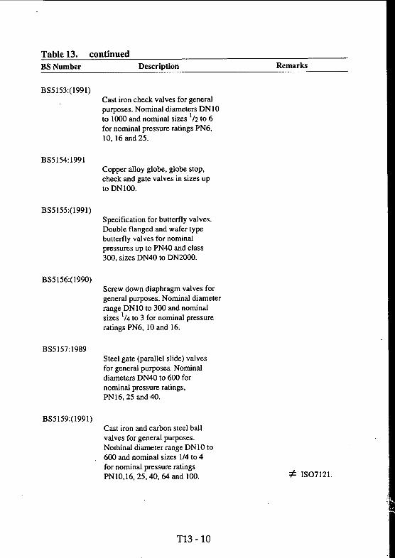
Table 13. continuedBS Number Description Remarks
BS5153:(1991)Cast iron check valves for general purposes. Nominal diameters DNIO to 1000 and nominal sizes '/2 to 6 for nominal pressure ratings PN6, 10, 16 and 25.
BS5154:1991Copper alloy globe, globe stop, check and gate valves in sizes up toDNlOO.
BS5155:(1991)Specification for butterfly valves. Double flanged and wafer type butterfly valves for nominal pressures up to PN40 and class 300, sizes DN40 to DN2000.
BS5156:(1990)Screw down diaphragm valves for general purposes. Nominal diameter range DNIO to 300 and nominal sizes ’/4 to 3 for nominal pressure ratings PN6, 10 and 16.
BS5157:1989Steel gate (parallel slide) valves for general purposes. Nominal diameters DN40 to 600 for nominal pressure ratings,PN16, 25 and 40.
BS5159;(1991)Cast iron and carbon steel ball valves for general purposes. Noihinal diameter range DNIO to 600 and nominal sizes 1/4 to 4 for nominal pressure ratings PN10,16, 25,40, 64 and 100. ■t- IS07121.
T13-10

Table 13. continuedBS Number Description Remarks
BS5160:1989Specification for flanged steel globe valves, globe stop and check valves for general purposes. Valves in nominal size range DN15 to450 with flanged ends to BS 4504 for pressure range PN16 to 40.
BS5169;1975■Fusion welded air receivers.Design rules and construction and inspection requirements for three classes of receiver. Maximum design pressures for Class I (unlimited), Class n (35 bar) and Class III (17.5 bar) vessels. Supersedes BS 487: Part 1 & 2 and BS 1099.
It should be noted that the new European Standard EN286 Part 1 covers a small part of the Scope of this British Standard. The revision of this British Standard will take the overlap into account.
BS5173 Methods of test for rubber andplastic hose assemblies.
BS5173Pt. 100:1992Introduction: A detailed explanation of the revisions to the 1976 and 1977 editions.Part 101-Determination of dimensions. Part 102-Hydraulic pressure tests.Part 103-Physical tests.Part 106-Environmental tests.
Twenty-nine sections in the four parts have been published.
Most are not relevant to compressed air hoses. For more details consult BSI catalogue or contact BCAS.
BS5222 Specification for aluminium piping WITHDRAWNsystems.
BS5276 Pressure vessel details (dimensions).
BS5276Pt. 1:1984Davits for branch covers. Dimensions and materials.
T13-11

Table 13. continuedBS Number Description Remarks
BS5276Pt. 2:1983Specification for saddle supports for horizontal cylindrical pressure vessels. Specifies dimensions and materials for saddle supports welded to stationary horizontal cylindrical pressure vessels in accordance with BS 5276:Part4.
BS5276 Pt. 3:1979Dimensional tolerances for ferrous pressure vessels and associated non pressure parts.
BS5276Pt. 4:1977Standardized pressure vessels. Cylindrical vessels with torispherical domed ends. Module system for shell cylinder lengths to economize manufacture of carbon steel and carbon manganese steel vessels by reducing the number of plate sizes used.
Replaces BS3161.
BS5315:1991
BS5319:1976
BS5327:1976
BS5380:1984
Specification for worm drive hose clips.
Specification for quick release vacuum WITHDRAWN, couplings (screwed and clamp type).
Specification for swept elbow bends for fluid power.
Specification for hydraulic ports and Relevant to pneumatic porting couplings using G threads. to seal with R type taper threads.
IS0228-1 andIS01179.
BS5391 Specification for ABS pressure pipe.
T 1 3-1 2

Table 13. continuedBS Number Description Remarks
BS5391 Pt. 1:1976Pipe for industrial uses.
BS5392. Specification for ABS pipe fittings.
BS5392Pt. 1:1976Solvent welded fittings for industrial use.
BS5409 Specification for nylon tubing.
BS5409Pt. 1:1976Fully plasticised nylon tubing types 11 and 12 for use primarily in pneumatic installations. Light and normal duty grades in a range of nominal outside diameters from 4 to 28mm, for use with pneumatic installations and for fluid transfer.
^ IS07628-1.
BS5418:(1984)Specification for the marking of general purpose industrial valves. Specifies mandatory and optional markings for valves and states the manner of applying the markings.
= ISO5209.
BS5500:1991Unfired fusion welded pressure vessels. Materials and design stresses; design calculations for scantlings of cylindrical and spherical shells, domed and flat ends, openings and branch connections, bolted flange connections, tubeplates; manufacturing procedures, tolerances, welding; inspection, non destructive and pressure testing for 3 categories of construction subject to internal or external pressure.
This calls for 3rd party inspection and results in more expensive vessels than BS 5169 but is preferred by some users and manufacturers. A voluminous series of BS 5500 documents give enquiry and other specific cases.
T13 -1 3

Table 13. continuedBS Number Description Remarks
BS5556:(1986)Specification for general requirements for dimension and pressure ratings for pipe of thermoplastic materials.
Replaces BS3867 and 4159.
^ IS0161/1.
BS6066:(1986)Specification for thermoplastic hoses for compressed air. Requirements for two types of textile reinforced thermoplastic hoses with working pressures of lObar and 16bar. = IS05774.
BS6323 Specification for seamless and welded An eight part standard, many partssteel tubes for automobile, mechanical not relevant to compressed air. and general engineering purposes.
BS6323;Pt.l:(1990)General requirements
BS6362:1990Stainless steel tubes suitable for screwing in accordance with BS 21. = IS07598.
BS6596:1992Ratios of proof and burst pressure of rubber and plastic hoses. = IS07751.
BS6597:1985Internal diameters and tolerances and length tolerances of rubber and plastic hoses. = ISO 1307.
BS6683:(1991)Guide to installation and use of valves
Relevant to Regulation 6 of the Pressure Systems Regulations. (S.I.2169.)
BS6755 Pt. 1:(1991)Production pressure testing of valves.(ReplacesBS 5146) Relevant to requirements of
Regulation 4 of S.I. 2169.ISO5208.
T13 -1 4

Table 13. continuedBS Number Description Remarks
BS6956 Jointing materials and compounds.
BS6956Pt.5 :1992Specification for jointing compounds for water and 1st and 2nd family gases.
BS6956 Pt.6;1992
BS6974:1991
BS7438:1991
Specification for jointing compounds for 3rd family gases for use with screwed connections.
Specification for unsintered PTFE Suitable for screwed joints up to tape for thread sealing applications. 80bar and up to at least 50mm
nominal bore with BS21 threads.
Specification for steel and copper alloy wafer check valves.
T13-15

Table 13. contiuedBS Number Description Remarks
Protective Equipment and Precautions
BS1123 Pt. 1:1987Code of Practice for installation of safety valves, gauges and fusible plugs for compressed air or inert gas installations. ^ IS04126.
BS1780:(1992)Specification for bourdon tube pressure and vacuum gauges 50mm to 300mm nominal size ranges up to lOOObar.
Will be replaced by a new European Standard EN472 which includes more comprehensive test procedures.
BS 1904; 1984Specifications for industrial platinum resistance thermometer sensors. = IEC751.
BS2915;1990Bursting discs and bursting disc assemblies, specifies requirements for protection of pressure or vacuum systems. ^ IS06718.
BS3636:(1985)Methods of proving gas tightness of vacuum or pressurised equipment.
BS4781: 1990Self adhesive plastic labels for permanent use.
Relevant to marking equipment to satisfy Regulation 5 of the Pressure Systems Regulations.
BS5228 Noise control on constructionand open sites.
BS5228Pt 1:1984Code of practice for information and procedures.
T13-16

Table 13. continuedBS Number Description Remarks
BS5228Pt 2:1984
BS5235:(1984)
Guide to legislation for construction and demolition including road maintenance.
Dial type expansion thermometers.
BS5345 Code of practice for selectioninstallation and maintenance of electrical apparatus in explosive atmospheres.
Consists of eight parts 1979 to 1990. Consult BCAS or BSI catalogue.
BS5378 Safety signs and colours
BS5378:Pt.l:1980Specification for colour and design for giving information to prevent accidents. IS03864.
BS5378 Pt.3;1982Additional signs to those given in Part 1.
BS5490:(1985)Specification for classification of WITHDRAWN
& degrees of protection provided by Superceded by BS EN60529:1992.BS5420 (1988) enclosures. A two digit code indicates
degree of protection including ingress of dirt and water.
BS5501 Electrical apparatus for potentiallyexplosive atmospheres.
BS5501 Pt 1:1977.General requirements. = EN50014.
BS5501 Pt3:1977.Pressurised apparatus. = EN50016.
BS5501 Pt5:1977Flameproof enclosures. = EN50018.
T13-17

Table 13. continuedBS Number Description Remarks
BS5501 Pt7:1988.Intrinsic safety. = EN50020.
BS5501 Pt9:1982.Specification for intrinsically safe systems. = EN50039.
BS6134:1991
BS6164:1982.
Specification for pressure and vacuum switches. Specifies the performance of switches for industrial use. Applies up to lOOObar for non flammable, non-corrosive, non toxic fluids and atmospheres. Does not apply to pressure difference switches, pressure indicating devices or switches with non-electrical outputs.
Code of practice for safety in tunnelling in the construction industry.
BS6327:1982Specification for fire protection of reciprocating internal combustion engines. = IS06826.
BS6759Pt 2:1984.Specification for safety valves for compressed air or inert gases.
Relevant to Regulation 4 of SI 2169. = IS04126.
T13-18

Table 13. continuedBS Number Description Remarks
Filters-dryers-lubricators
BS1747:(1990/91)Methods for measurement of air pollution.
A ten part standard relevant to checking air quality.
BS1752:(1989)Sintered or fritted filters including porosity grading. = IS04793.
BS2540:1991 Specification for granular desiccant silica gel
BS3482:1991Methods of test for desiccants. An 11 part standard.
BS3523:1991
BS3928:1969
Specifications for granular desiccant silica gel impregnated with cobalt chloride.
Method for sodium flame test for air Compressed air line filter element filters (other than for air supply to i.c. grading. (See also BS 5600.) engines and compressors) grading.
BS4001 Care and maintenance of underwaterbreathing apparatus.
BS4001 Pt. 2:1967Standard diving equipment including Will be replaced by newair purity. European standard.
BS4275:1974
BS4400:1969
Recommendation for the selection, Will be replaced by new use and maintenance of respiratory European standard. See protective equipment includes air also CEN report CR529. purity.
Sodium Chloride test for respiratory filters.
T13-19

Table 13. continuedBS Number Description Remarks
BS4667 Pt. 3:1974Compressed airline breathing apparatus.
Will be replaced by new European standard EN139.
BS5600 Powder metallurgical materials and products.
BS5600 Section 3.5:(1987)Determination of bubble test pore size for permeable sintered metal materials.Methods for determining the pore size of filters.
Compressed air line filter element grading.
= IS04003.
BS6005:1981 Specification for mouldedtransparent polycarbonate bowls used in compressed air filters and lubricators.Requirements for the manufacture, inspection, testing and labelling of pressure containing (10 bar and exceptionally 16 bar) compressed air filter and lubricator bowls which are moulded in transparent polycarbonate. Appendix gives guidance on proper installation, use and maintenance of units fitted with these bowls.
Appendix is relevant to compliance with the Pressure Systems Regulations 1989.An amendment to change the test fluid from carbon tetrachloride to a toluene/propanol mixture is under consideration.
BS6202:1982
BS6413
Glossary of terms for cleaning equipment for air and gases.
Lubricants.= IS03649.
BS6413Pt. 1:(1991)Total loss systems.
BS6754:1986Specifications and testing of compressed air dryers.
= IS06743-1.
= IS07183.
T13 - 20

Table 13. continuedBS Number Description Remarks
BS7444:1991
BS7554:1992
BS673:1984
BS1042
Specification for molecular sieves of type 4A.
Specification for beaded desiccant silica gel.
Compressors, Vacuum Plant And Pneumatic Tools.
Shanks for pneumatic tools and fittings dimensions of chuck bushings.
Measurement of fluid flow in closed circuits.
= ISO 1180.
BS1571 Pt. 1:1987
A Multi-part standard covering venturi nozzles and orifice plates for measuring gas flow.
Acceptance tests for compressors and exhausters.Acceptance tests and technical conditions for the supply of displacement compressors and certain types of displacement vacuum pumps.Detailed instructions on capacity measurement and power consumption and means of adjusting the measured values to guaranteed conditions. Supersedes, with Part 2, BS 726:1957 andBS 1571:1949.
The internationally accepted type test for air and gas compressors.
= IS01217.
BS1571 Pt. 2(:1984)Simplified acceptance tests for air compressors and exhausters. Simplified testing of reciprocating and rotary types including permissible deviations. Pressure and temperature measurements and arrangement of tests. Form of test report and gives adjustment of test results to guarantee conditions. Supersedes BS 726.
‘Due for revision’.See PNEUROP/CAGI Performance test codes from BCAS
T13 - 21

Table 13. continuedBS Number Description Remarks
BS1701:1970 WITHDRAWN.
BS2009:1953
See BS7226.
Code of acceptance tests for turbo type compressors and exhausters.
BS2806:1956Limiting dimensions of air filters for OBSOLESCENTinternal combustion engines andcompressors.
BS4142:1990
BS4196
BS4231:(1988)
Method for rating industrial noise affecting mixed residential and industrial areas.
■ t- IS01996-l,-2,-3.
Sound power levels of noise sources. A nine part standard.Methods of rheasurement. = ISO3740 through IS03747
' and IS06926.
Classification for viscosity grades of industrial liquid lubricants. Covers 18grades of petroleum lubricants in the _viscosity range 2cSt to 1 SOOcSt at 40 C. ~ IS03448.
BS4278:1984Specification for eyebolts for lifting purposes. = IS03266.
BS43901969Specification for portable pneumatic grinding machines for wheels up to 250mm.
BS4957:1973Medical vacuum pipe lines in hospitals. WITHDRAWN.
T13 - 22

Table 13. continuedBS Number Description Remarks
BS5344:(1990)
BS5719;1984
BS5758
BS5791
Part 1:(1990)
Part2:(1990)
Part 3:1990
BS5914:1980
BS6077:1981
Methods for acceptance tests for rotary and percussive tools.Acceptance tests and technical conditions for the supply of pneumatic tools. Includes a simplified test for percussive tools that have been type approved by a full acceptance test.
Positive displacement vacuum pumps.
Vapour vacuum pumps.
Glossary of terms for compressors, pneumatic tools and machines.
General.
Compressors - Technical terms relating to compressors.
Pneumatic tools and machines.
Methods of calibrating leak-detectors of the mass-spectrometer type used in the field of vacuum technology. Specifies procedures for determining a sensitivity figure for mass-spectrometer type leak detectors.
Specification for dimensions of quick release couplings for the screwed type used in vacuum technology.
= IS02787.
WITHDRAWN.
WITHDRAWN.
= IS03857- 1.
= IS03857- 2.
= IS03857- 3
= ISO3530.
WITHDRAWN.
T13 - 23

Table 13. continuedBS Number Description Remarks
BS6244:1982Code of practice for stationary air compressors. Establishes standards for the safe design, construction, installation and operation of stationary and skid-mounted air compressors for general use. Specifies requirements to help minimize compressor accidents and defines general safety practices for the field. Potential hazards associated with compressors are listed and detailed.
Under revision.
= IS05388.
BS6268:1982Method of measurement for reaction torque impulse from hand held pneumatic assembly tools for installing threaded fasteners. Describes the test method for measurement of reaction torque and specifies how such measurements should be evaluated. = IS06544.
BS6292:1982Method for evaluation of performance of rotary pneumatic assembly tools for threaded fasteners. Covers the performance test methods for measurement of installation torque of pneumatic assembly tools for tightening of threaded fasteners and how such tests should be evaluated and presented. = IS05393.
BS6413 Lubricants.
BS6413 Section 3.1:1988.Air compressor lubricants.
BS6416:1983Nomenclature for assembly tools for screws and nuts.
IS06743-3A. Proposed for confirmation
= ISO1703.
T13 - 24

Table 13. continuedBS Number Description Remarks
BS6742 Electrostatic painting equipment.
BS6742Pt. 1:1987Hand held spray guns and associated apparatus. = EN50050.
BS6742Pt. 2:1987Selection, installation and use of hand held spray guns and associated equipment. = EN50053Pt.l.
BS6805 Statistical methods for determining andverifying stated noise emission values of machinery equipment.
BS6805Pt. 1:1987Glossary of terms.
IS07574-1 and EN27574-1.
BS6805 Pt. 2:1987Method for determining and verifying stated values for individual machines.
IS07574-2 and EN27574-2.
BS6805Pt. 3:1987Determining stated values for batches of machines using a simple method.
BS6805Pt. 4:1987
BS6842:1987
Methods for determining and verifying stated values for batches of machines.
Guide to measurement and evaluation of human exposure to hand vibration.
IS07574-3 and EN27574-3.
IS07574-4 and EN27574-4.
^ IS05349.
BS7025:1988Method for preparation of test codes for measurement at the operator’s position of noise emitted by machinery. ^ ISO6081.
T13 - 25

Table 13. continuedBS Number Decsription Remarks
BS7086:1989Glossary of terms for pneumatic tools. = IS05391.
BS7226;1989Methods of test of inlet air cleaning equipment for compressors.
= ISO5011 and replaces BS1701. -
BS7316:1990Design and construction of screw and related type compressors for the process industry. = ISO8010.
BS7321:1990Design and construction of the turbo type compressors for the process industry. = ISO8011.
BS7322:1990Design and construction of reciprocating compressors for the process industry. = ISO8012.
BS7405:1991Guide to the selection and application of flowmeters.
BS7482:1991Instrumentation for the measurement of vibration exposure of human beings.
A multi-part standard.
T13 - 26

Table 13. continuedBS Number Description Remarks
BS4151:(1986)
Pneumatic Control Equipment.
Method of evaluating pneumatic valve positioners with input signal 0.2 to Ibar.
BS4518:1982Specification for metric dimensions of The metric ‘O’ ring standardtoroidal sealing rings (‘O’ rings) and their housings. Specifies dimensions and tolerances of toroidal sealing rings for hydraulic and pneumatic applications in static and dynamic situations. Also specifies the appropriate housing dimensions when used at pressures up to 100 bar.
most widely used by UK makers of compressed air equipment. Originally based on a Swedish standard.
BS4575Pt. 2:1987Code of practice for pneumatic equipment and systems. Recommendations to suppliers and users for design use including safety recommendations.
^ IS04414.
BS4575 Pt. 3:1988Code of practice for specification design, construction, commissioning and safe application of pneumatic fluid power systems.
Requirement will probably form part of a new European standard on Machine Safety.
BS4832:1987Specification for compatibility between elastomers and hydraulic fluids. Also relevant to compatibility of lubricating oils.
= ISO6072.
BS4862 Mounting dimensions of single roddouble acting 10 bar pneumatic cylinders.
BS 4862 is near universally accepted by European makers of pneumatic cylinders.
T13 - 27

Table 13. continuedBS Number Description Remarks
BS4862Pt. 1:1983Specification for cylinders up to 25 mm bore. Specifies interchangeability dimensions for four mounting styles of cylinder with bores in the range 8mm to 25mm.
= IS06432.
BS4862Pt. 2:1983Specifications for cyliders, 32mm bore and over, with detachable mountings. Specifies interchangeability dimensions for seven mounting styles of cylinder with bores in the range 32mm to 320 mm for operation at ambient temperatures of-20°Cto70°C. = IS06431.
BS5242 Tubes for fluid power cylinder barrels.
BS5242 Pt.l:1987Steel tubes with specially finished bores. Mechanical properties, dimensional requirements, tolerances, surface texture and technical delivery conditions for tubes for use as barrels for fluid power cylinders.
^ IS04394-1.
BS5242Pt. 2:1983Specification for non ferrous metallic tubes with specially finished bores. Mechanical properties, dimensional requirements, tolerances, surface texture and technical delivery conditions for tubes used as barrels for fluid power cylinders.
= IS06537.
BS5304:1988Code of practice for safety of machinery.
Will eventually be incorporated into European Standards on machine safety.
BS5755:1986Dimensions of basic features of fluid power cylinders.
= ISO3320, 3322, 4393 4395 and 7181.
T13 - 28

Table 13. continuedBS NUmber Description Remarks
BS6361:1988Specification for three pin plug The ’Hirschmann plug’connectors for electrically controlled institutionalised,fluid power equipment. Characteristics and requirements for a general purpose three pin electrical connector with earthcontact for use with single solenoid =: IS04400.operators for fluid power control valves.
BS6805 Noise emission of machinery and.equipment.
SEE COMPRESSOR SECTION.
BS7294:1990Determination of flowrate characteristics of pneumatic fluid power components.
Not applicable to low pressure drop components e.g. filters, lubricators.
= IS06358.
BS7388:1991Guide for prevention of leaks from Also has relevance to pneumatic hydraulic fluid power systems. systems.
BS7389Pt. 1:1990Mounting surfaces for five port peumatic fluid power directional control valves without electrical connectors.
= IS05591-1.
BS7405:191Guide to the selection and application of flowmeters.
T13 - 29

Table 13. continuedBS Number Description Remarks
Symbols - Units - Tables.
BS1339:(1981)Definition, formulae and constants relating to the humidity of the air.
Includes tables of saturation vapour pressure.
IS06194-3.
BS1553
Part 1:1977
Part 3:1950
BS2045;(1982)
Graphical symbols for general engineering.
Piping systems and plant. BCAS prefers to use BS2917.
Compressing plant.
Series of preferred numbers R5 to R80 Assists in reducing discussion series and guidance on their use. when it is necessary to select a
numerical value.= IS03,17and497.
BS2856:1973
BS2917:1977
BS3641
Precise conversion of inch to metric on engineering drawings.
Specification for graphical symbols used on diagrams for fluid power systems and components. Principles for use of symbols.Symbols to be used on diagrams of hydraulic and pneumatic transmission systems and components.
Symbols for machine tools.
Provides for precise dimensional interchangeability.
ISO 1219:1991 now published; not yet dual numbered at time of this guide going to press.
BS3641 Pt. 1:(1990)General symbols. Designs, drawings Some of these symbols are used for form of symbols, not dimensional on compressed air equipment, representations; recommendations for proportions in design of symbols,independent of dimensions. ■■ ^ IS O /R 369 .__
T13-30

Table 13. continuedBS Number Description Remarks
BS3641 Pt. 2:(1987)Specification for numerical control symbols. Basic designs for symbols for use on indicator plates of numerically controlled machine tools. 5^ IS02972.
BS3641 Pt. 3:(1990)Additional general symbols. Additions See also supplement to BS3641.to symbols in Part 1. Recommendsproportions to be used in design ofsymbols independent of actualdimensions and provides for groupingsymbols selected from the same ordifferent sections according toindividual requirements. ISO/R369.
BS3763:1976The International System of Units WITHDRAWN
See BS5555:1981.
BS3939 Graphical symbols for electricalpower, telecommunications and electronic diagrams.
BS4099 Colours of indicator lights, pushbuttons, annunciators and digital readouts.
A multi-part standard.
= IEC617-1 through 13.
Relevant to pneumatic indicators.
BS4099Pt. 1:1986Specification for colours to be used. = IEC73.
BS4099 Pt.2:(1986)Specification for flashing lights annunciators and digital readouts.
Partially replaced by BS4099 Pt. 1.
BS4884 Specification for Technical Manuals.
BS4884Pt. 1:1992Content - Information to be given on use, maintenance and repair.
T13 - 31

Table 13. continuedBS Number Description Remarks
BS4884Pt.2:(1983)Specifies requirements for the presentation of information in technical manuals.
Under revision
BS4899 Guide to users requirements fortechnical manuals.
Based on the principles of BS4884.
BS4899 Pt. 1:1992Content.
BS4899 Pt.2:1992Presentation.
BS5374:1989Codes for the representation of the names of countries.
= IS03166.
BS5378 Safety Signs and colours See section on protective equipment.
BS5497 Precision of test methods.
BS5497 Pt. 1 :1987Guide for determination of repeatability and reproducibility by inter-laboratory tests.
= IS05725.
BS5543:1978Vacuum technology-Graphical Symbols. For convenience for drawings, recommends positions of inlets and outlets to devices.
= IS03753.
BS5555:(1987)Specification for SI units and recommendations for the use of their multiples and of certain other units. Recommendations and advice on using and selecting units of the International System (SI) in industry and technology. Describes the system and lists certain other units which may be used in conjunction with it. = ISOIOOO.
T13 - 32

Table 13. continuedBS Number Description Remarks
BS5739;1979Method of presentation of lubrication Relevant to lubrication of tools instmctions for machine tools. Gives and pneumatic controls, guidance on the information to be provided and specifies the manner ofpresentation. ^ ISOS 169.
BS5750:1987 1990 and 1991Quality systems. A multi part standard on quality systems. The basis for the BCAS Sector Scheme.
BS5760 Reliability of constructed or manufacturedproducts, components and systems. A seven part guide to reliability 1981 through 1991.
= IS09000and EN29000.
BS5848:(1986)Numbering of divisions and sub-divisions in documents. = IS02145.
BS5875:1991Glossary of terms and symbols for measurement of fluid flow in closed circuits. = IS04006.
BS6069 Characterization of air quality.
BS6069Pt. 1:(1987)Units of measurement. = IS04226.
BS6069Pt2:(1987)Glossary of terms. = IS04225.
BS7151:1989Representation of dates and times in national and international data exchange. = ISO8601.
BS7324:1990Graphical symbols for use on equipment. = IS07000.
T13 - 33

Table 13. continuedBS Number Description Remarks
BS7477:1991Guide to general principles for creation of graphical symbols for use on equipment. = IS03461-1.
BS7750:1992Specification for environmental management systems. Aimed at ensuring compliance with environmental policy and objectives.
BSPD5686:1978 WITHDRAWN
Footnotes:
See BS5555.
Selection must be, at least in part, arbitrary and to cast the net too wide would defeat its purpose. For instance, compressed air technology is largely one of moderate pressures ( e.g. compared to hydraulics) and temperatures calling for little use of alloy steels, particularly in vessels and piping. Nevertheless, some stainless (austenitic) steel (tubing etc.) specifications have been included, bearing in mind the increasing use of compressed air equipment by the offshore, pharmaceutical and electronic industry and in the resulting needs of corrosion resistance...
Certain ISO standards referred to in the Remarks columns of this Table do not appear in the table of ISO standards which is more generally corifihed to those relating to compressed air only.
= means identical to the ISO or EN standard
= means technically equivalent to the ISO or EN standard
means related to but not equivalent to the ISO or EN standard
For a more detailed description of a British Standard the reader is advised to consult the BSI catalogue copies of which are available in major public libraries as well as those of technical universities, colleges and polytechnics.
T13 - 34

Table 14 European Standards
The data in this table are extracted from ‘BSI Catalogue 1992’ (the position at 22 February 1992) updated to 30 June 1992 where more recent information is available.
Whereas with International Standards adoption as British Standards is optional the agreement between BSI and CEN requires that all European Standards shall become British Standards and that any existing British Standard which is in conflict with the European Standard shall be withdrawn.
The original procedure for converting a European into a British Standard was to dual number eg ENxxx BSyyy as is the current practice with International Standards. Since 1988 however European Standards that have been adopted as British Standards retain their EN number preceded by the letters BS.
EN Number ' Description Remarks
EN68:1977 Hand held (portable) power driven grinding machines - mechanical safety.
This standard will be withdrawn when EN 792 Part 7 is published in 1994. No corresponding BS
EN139 Compressed Air Line Breathing Apparatus incorporating a facepiece.In final draft form.
Will become a British Standard Replacing BS 4667 Part 3
EN270 Compressed Air Line Breathing Apparatus incorporating a hood. In final draft form.
Will become a British Standard
EN271 Compressed Air Line Breathing Apparatus for use in blasting operations. In final draft form.
Will become a British Standard
BS EN286 Specification for simple unfired pressure vessels.
30 bar maximum pressure. Pressure Volume relationship 50 to 10 000 bar. litre.
Part 1:1991 Design, manufacture and testing. Partly replaces BS5169
BS EN292 Safety of Machinery. Basic concepts, general principles for design.
Principle standard for use with the Machinery Safety Directive (See 12.5)
T14-1

EN Number Description Remarks
EN 292 Pt 1:1991 Terminology, methodology.
EN 292 Pt 2:1991 Technical principles and specifications.
BS EN414:1992 Safety of machinery - Rules for drafting and presentation of safety standardis.
This standard applies to the formulation of standards prepared for use
by manufacturers in connection with the Machinery Safety Directive. (See 12.5)
BSEN457:1992 Safety of machinery - Auditory dangersignals. Requirements design and testing.
EN472
EN689
Bourdon tube pressure gauges: dimensions, metrology, requirements and testing.
Guidance for assessment of exposure to chemical agents in the workplace.Draft standard.
^ IS07731.
Will replace BS1780.
BSI document 92/52696.
EN792
BS EN2070
Part 1:1990
Part 5:1991
Handheld non-electric power tools:Part 1 General Safety RequirementsPart 2 Safety of energy supplyPart 3 Rotary drills and tappersPart 4 Percussive non rotary toolsPart 5 Rotary percussive drillsPart 6 Assembly tools for threaded fastenersPart 7 Grinding machinesPart 8 Polishers and sandersPart 9 Die grindersPartlO Squeeze riveters, presses, punchesParti 1 Cutting power toolsPart 12 Power sawsPart 13 Nailers, staplers, lackers
Specification for aluminium and aluminium alloy wrought products.
General requirements, inspection and testing.
Extruded tubes for use under pressure.
In course of preparation.Due in 1993Due in 1993Due in 1993Due in 1993Due in 1993Due in 1993
Due in 1993 Due in 1993 Due in 1993 Due in 1993
T14-2

EN Number Description Remarks
BS EN10207;1992 Steels for simple pressure vessels.
EN24230:1990 Screwing dies for taper pipe threads R series.
EN24231:1990 Screwing dies for parallel pipe threads G series.
EN27574 Methods for determining and verifying statednoise emission values of machinery and equipment.
= BS1127Pt.2.
= BS1127Pt.3.
EN27574-1:1988 Glossary of terms
EN27574-2; 1988 Determining and verifying stated values for individual machines.
= BS6805Pt.l.
= BS6805Pt.2.
EN27574-3:1988 Determining and verifying stated values for batches of machines (simple method). = BS6805Pt.3.
EN27574-4:1988 Determining and verifying stated values for batches of machines. = BS6805Pt.4.
EN29000:1987 Quality systems - Guide to selection and use.
EN29001:1987 Specification for design/development,production, installation and servicing.
EN290(}2:1987 Specification for production and installation.
EN290Q3:1987 Specification for final inspection and test.
EN29(XM: 1987 Guide to quality management and quality system elements.
= BS5750Part0 Section 0.1.
= BS5750Part 1.
= BS5750Part2.
= BS5750Part3.
= BS5750Part0 Section 0.2.
EN45014:1989 General criteria for suppliers declarationof conformity.
= BS7514.
BSEN45020:1991 Glossary of terms for standardisation and related activities.
T 14-3

EN Number' Description Remarks
EN50014:1977 Electrical apparatus for potentially explosive atmospheres - General requirements.
= BS5501 Pt.l.
EN50016; 1977 Pressurised apparatus for explosive atmospheres.
EN50018:1977 Flameproof enclosure.
EN50019:1977 Apparatus that does not produce sparks.
EN50020:1977 Intrinsically safe apparatus.
EN50039:1982 Construction and testing of intrinsicallysafe systems.
= BS5501 Part 3.
= BS5501 Part 5.
= BS5501 Part 6.
= BS5501 Part 7.
= BS5501 Part 9.
EN50050:1987 Electrostatic hand held spray guns using flammable materials. = BS6742Part 1.
EN500S3 Specification, installation and use of handPart 1:1987 held paint spray guns (energy limit 0.24mJ). = BS6742Part2.
ENS0PS3. Specification, installation and use ofPart 2:1989 hand held powder spray
, . guns (energy limit 5mJ).= BS6742Part3.
EN5(X)53 Specification, installation and use ofPart 3:1989 hand held flock spray guns
(energy limit of 0.24 mJ or 5mJ).= BS6742Part4.
BS EN50059:1991 Electrostatic hand held spray, guns for non flammable materials for painting.
EN5d099-l Safety of machinery. Visual andaudible signals. Draft standard.
BSI document 92/24817.
EN50099-2 Safety of machinery. Markingprinciples. Draft standard.
BSI document 92/24818
BS EN60529:1992 Specification for degrees of protection, provided by enclosures (IP Code).
= DEC529 and replaces BS5490.
T 14-4

Table 15 Publications
The following publications are available from BCAS.
1 BCAS Publications
1.1 Air Treatment and General Serviees BUYERS GUIDE to Compressed Air Plant and Equipment.BCAS Recommendation 860900 on Filters for Compressed Air
- Methods of TestPart 1 - Pressure Drop and Oil Mist Removal Test Procedure for Coalescing Filters.BCAS Recommendation 860901 on Filters for Compressed Air
- Methods of TestPart 2 - Adsorbent Pack Filters for Hydrocarbon Vapours.The above recommendations are the basis for the BRITISH STANDARD in the course of preparation.
1.2 Air SpecificationRespirable Air - For general industrial, rescue and escape purposes for use at, or near, normal atmospheric pressure.Papers from the "Breathing Air" Seminar.Selected papers covering "The Problems of Specifying Air and Equipment to Satisfy User Requirements and the Law"]
1.3 Legislation and RegulationsPRESSURE SYSTEMS LEGISLATIONBCAS Guidance and Interpretation on the Health & Safety Commission Regulations and Approved Code of Practice
Part 1 THE REGULATIONS Part 2 THE APPROVED CODE OF PRACTICE Part 3 FOR THE DESIGNER, INSTALLER, COMPETENT PERSON AND MAINTENANCE PERSONNEL Part 4 FOR OWNERS AND USERS
Available as a set of three parts or Part 4 alone.PRESSURE SYSTEMS VIDEO PACK(Includes H & SE Code Of Practice, and BCAS Part 4).
T15-1

2 PNEUROP Publications
2.1 Air Treatment and General Services6603(1980)Compressed Air Dryers
Specification & Testing NOW BS6754 AND ISO 7183 6607(1980)A simplified Method for Air Volume Flow Rate Measurement by
means of circular arc venturi nozzles 66110(1984)Compressed Air for General Use
Part I: Quality ClassesPart II: Methods for determination of oil in Compressed Air etc
2.2 Legislation and RegulationsPRODUCT LIABILITY "A Company Action Plan"This 146 page document has been produced as the complete guidance for the European Compressed Air Industry.It cover's legal considerations, safe use, misuse, quality assurance, insurance, symbols & signs, glossary of terms, list of standards Md3janq83^ppint,;aetm plan and check list.
no!fK-jni:^3qP £.1EURgj’E^.eM AgHD^Egl^ DHlE.GTIiYEEGOI^QFUvII^Y-MThis manual is a high quality four-ring bindgrgyVjUhjS e y enfGha joall that any company needs to know iniorder; tqjsetgab.outj the taskf,qf-,|co.mplianc^ij^ith5t^-EurQp,ean:;DJjrec,ti>ven8S!(392/EEG"an^^^^direcuve 91/368/EEC. vj .UIt comes complete with copies of the Directives, EN292 parts 1 & 2,A management Action Plan, guidance onGHandbpokS)j& D,qeum^nta^tion, guidance on production of the Technical'iQonstrjjqtipn [File'i^ndxavcQpy^jofiq^iq a Certificate-,qf^iQonformity^ fijliibH odJ no noiiiiJoKpsJn! bm; sjncuiuD SADII Purchase of this manual includes participation iji>can updating^^seryjceaoiinluprjlJ
R/10JTAJlJOa;i .HHT I nn*I2.3 Noise and y ib rajionq q o HOOD agVO fiaaA HHT £ nnH
560 (d; 6^9Me^asur ent ^ Spund^fipjn]f*njumatk*:E5uipiM p p,:q 6610(1978)Test Procedure for the J4easu5einent pf3Yite4tion/[frqm hand held(portable) Power Driven GrindingpMachines. gyiHVIWO HOT b nuH 66160(1985)Test Procedure for <the[|Measurement-ofj YibfatiQnjfrom^GhippingvA Hammers )i3Aq OHGIV ?,MaT8Y?.PNEUROP SC8 Working ,Grqup/RepoiJ,pn3 ^EURQP;,boO 3Z & II '-jboi'jriO Sound Test Code (background and Experience of its Application)
iT-15r-i2

2.4 Terminology and Symbols5601(1969)Compressors, Classification & Glossary of Technical Terms 56172(1977)Graphical Symbols for Control and Instrument Panels on Rock Drilling Rigs
2.5 CompressorsPNEUROP/CAGI ACCEPTANCE TEST CODES Measurements using these codes are less demanding than for example IS01217 methods and therefore are within the scope of a user who wishes to verify compressor performance as quoted by manufacturers literature covering series built machines. 'PN2CPTC1ACCEPTANPCE TEST CODE FOR BARE DISPLACEMENT AIRCOMPRESSORSPN2CPTC2ACCEPTANCE TEST CODE FOR ELECTRICALLY DRIVEN PACKAGEDDISPLACEMENT AIR COMPRESSORSPN2CPTC3ACCEPTANCE TEST CODE FOR I.C. ENGINE DRIVEN PACKAGED DISPLACEMENT AIR COMPRESSORS
PNEUROP Safety Recommendation for the Use and Operation of Portable Air Compressors(Illustrated)PNEUROP Safety Recommendation for the Use and Operation of Stationary Air Compressors (Illustrated)
2.6 Industrial and Contractors Tools
01/1987Test Procedure for the Measurement of Dust Emissions from Hand-held (Portable) Power Driven Tools - General Measuring Regulation02/1987Test Procedure for the Measurement of Dust Emissions from Hand-held (Portable) Power Driven Tools Percussive and Chipping Tools 03/1987Test Procedure for the Measurement of Dust Emissions from Hand-held (Portable) Power Driven Tools Saws,Shapers, Planers04/1987Test Procedure for the Measurement of Dust Emissions from Grinders
T 15-3

05/1987CAGI/PNEUROP - Standard for Electronic Interfaces for Pneumatic Tools18/1986Recommendations for the proper use of hand held or hand operated Pneumatic ToolsPNEUROP pamphlet - "Pneumatic Tools - Safety in Operation"(Illustrated) (Photocopy)
2.7 Vacuum Technology5607(1972)Vacuum Pumps, Rules of Acceptance: Part II (Vapour Pumps) 5608(1973)Vacuum Pumps, Rules of Acceptance: Part III(Turbomolecular- Pumps)5615(1976)Vacuum Pumps, Rules of Acceptance: Part IV(Sputter Ion Pumps) 6601(1978)Application of National Standards for Acceptance and capacity measurement of Steam Jet Vacuum Pumps and Steam Jet Compressors
6602(1979)Vacuum Pumps, Rules of Acceptance: Part I (Positive Displacement Pumps-Roots Pumps)
PN5ASRCC/5PNEUROP ACCEPTANCE Specification for Refrigerator Cooled Cryopumps Part 5
6606(1981)Vacuum Flanges and Connections - Dimensions
66120(1984)Acceptance Specification for Liquid Ring Vacuum Pumps
T15-4

3 CETOP Publications Available in English, French, German
3.1 Air IVeatment and General ServicesAll publications in this section are now ISO standards
3.2 Legislation and Regulations
3.3 Noise and Vibration
3.4 Terminology and SymbolsRP 4 IP Hydraulic & Pneumatic Circuits, Circuit DiagramRP 49P Technological Symbols for Fluid Logic & Related Devices with &without moving partsRP 68P Identification Code for Ports & Operators of Pneumatic Control Valves RP 101 Lexicon of Terms from Hydraulic & Pneumatic Fluid Power
3.5 ValvesRP 20P Pneumatic Flow Control ValvesRP 22P Pneumatic Shuttle, Non-Return & Quick Exhaust Valves RP 57P Pressure Relief Valves - Recommended Data for inclusion in Manufacturers’ Technical Sales Literature
3.6 CylindersR 4P Pneumatic Cylinders, suggested Data for inclusion as a minimum inManufacturers’ Technical Sales LiteratureRP 23P Pneumatic Pressure IntensifiersRP 24P Pneumatic Rectilinear Piston Type CylindersRP 105P Pneumatic Fluid Power Acceptance Test for Pneumatic CylindersRP 107P Fixed Pivot Bracket for Pneumatic Cylinders
3.7 Hoses - l\ibes - FittingsRP 28P ConnectionsRP 29P Pneumatic Quick-Action Couplings RP 30P Pneumatic Rotating & Telescopic Joints RP 34P Couplings for Industrial Air Hoses - 10 BarRP 38P Guidance on Relation Between Port Threads & Pipe Hose Diameters RP 40PN Hose CoupUngs, Claw TVpe & Amendments RP 54P Specification for Polymide Tubing 11 & 12 for Pneumatic TransmissionsRP 80 Cone Type Connection -24® for Fluid Power Tubes & Hoses
T 15-5

4.0ther Publications
The following publications are refered to in the main text.
4.1 Industrial Screw Threads - compiled by B P Mills and published by The Institute of Measurement and Control.
4.2 Compressed Air Safety - British Quarrying and Slag Federation.
4.3 Compressed Air Safety - H & S E Publication HS(G)39.
4.4 Guidance Note GS8 To the Health and Safety at Work Act issued by H & SE.
4.5 Occupational Exposure Limits - H & SE publication EH40; issued annually.
The publications above are not available from BCAS.
t l 5 - 6

Table 16. The International System of Units (SI)
Any given physical quantity, be it length, time, work, etc. is the product of numerical value and a unit.
The unit can be chosen arbitrarily, but it is advisable to define units in such a way that they are derived from a few fundamental units by equations without any numerical factors other than unity, and that the equations between numerical values of quantities have the same form as the equations between the quantities.A system defined in this way is called a coherent system.
A coherent system is formed by defining the fundamental quantities independently. These are called fundamental units.
The units of all other quantities are defined by equations with no numerical factors other than unity, and are called derived units. It is arbitrary which quantities, and how many, should be considered as fundamental.
In the absolute system the fundamental quantities are length, mass and time. International co-operation in the field of quantities and units started in 1875, when the Comite International des Poids et Mesures (CIPM) was founded. Various unit systems have since then been proposed and used. The biggest step forward towards a really international unit system was taken when CIPM in 1960, adopted le Systeme International d’Unit^s, with the abbreviation SI. Since then practically every nation in the world has accepted it, and made it legally binding.
The system includes three classes of units:
base units
supplementary units
derived units
T16-1

The Intemationd System of Units is founded on seyen base units:Table 16.1
Quantity Name Symbol
length metre mmass kilogram kgtime second selectric current ampere A.thermodynamic temperature kelvin Kluminous intensity candela cdamount of substance mole mol
Supplementary units are radian (rad) for plane angle and steradian (sr) forsolid angle.
Derived units are expressed in terms of base or supplementary units.Those of interest are:Table 16.2
Expressed in base orQuantity . Name Symbol supplementary units
frequency hertz Hz 1 Hz = Is'*force newton N 1 N = 1 kg.m.s'^pressure and stress pascal Pa 1 Pa = 1 N.m'^work, energy, quantity of heat joule J 1 J = 1 N.m
1 W = 1 J.s'*1 V = 1 W .A '*
power watt Welectric tension volt Velectric capacitance farad F 1 F = 1 A .S .V *
1 n = iv .A ' *electric resistance ohm Qinductance henry H 1 H = 1 V .S .A '*
It is recommended that work energy and quantity of heat be expressed in joules (J) but the moment of force (torque) be expressed in newton metres (N:m).
T16-2

Besides the units described in 16.2 the Comit6 International des Poids et Mesures has recognized certain units that have such practical importance that they must be retained for general use.The most important are given below:Table 16.3
Quantity Name of unit Symbol Definitiontime minute min 1 min = 60 s
hour h 1 h = 60 minday d 1 d = 24 h
volume htre L* 1 L = 1 dm^fluid pressure bar bar 1 bar = 10 Pa*Because of the possibility of confusing the typescript 1 with the numeral 1, it is advisable in cases of doubt to spell out ’litre’ or use dm^.However, the 16th meeting of the CGPM in October 1979 approved the use of the alternative symbol L for litre in order to avoid this confusion and will follow developments in the usage of both L and 1 with the aim, in the long term, of abohshing one of them.The responsible British Standards Committee OC/127 supports the use of L as the only symbol to be used.
Multiples of Sl-units. The following prefixes are used to form names and symbols of multiples of the SI units:Table 16.4
Symbol NameFactor by which the
T tera 10^^G giga 10^M mega 10®k kilo 10^h hecto 10^da deca 10*d deci 10'*c centi 10'^m mill! 10'^It micro lO"®n nano 10'^P pico 10'*^
T 16-3

Units in General Use in the Compressed Air Industry.Because the SI permits some choice of alternative units which could be confusing, the Compressed Air Industry has decided to standardize on certain units as shown below:Table 16.5
Description Units NotesLinear metres (m) above 1000 mm
millimetres (mm) below 1000 mmVolume (see Note 1) m above 1000 litreslitres L = decimetres^ (dm^) below 1000 litresReceiver capacity m^ above 1000 litres
L below 1000 litresVelocity metres/second (m/s)(gas or piston speed) Rate of a ir flow m^/s large compressors(see Note 2) L/s or m^/h smaller compressors
dm^/s pneumatic control
Speed of rotation rpmequipmentr/s is the consistent unit
Lifting capacity kg or t
but rpm is well established in practicet = tonne = 1000 kg
Pressure bar
being more practical than the theoretically correct unit the Newton (N)1 bar = 100 kPa
(seeNote 3) Torque N.mWork/energy/ Joule (J)quantity of heat Power W or kW The use of bhp is obsolete
Speciflc power kW.s/m^ = J/dm^
and is replaced by the wording ’brake power’
consumption
Gauge tem perature degrees C 1°C = K - 273.16Kinematic viscosity cSt IcSt = 10'^ m^/s
T 16-4

Notes1 The compressor and air tool manufacturers prefer litres; pneumaticequipment manufacturers prefer dm3. '2 Normally quoted as free air at specified conditions. In the case of air - compressors the conditions are usually those prevailing at the compressor - inlet. For pneumatic tools and control equipment the conditions are those of a standard reference atmosphere (ANR). Use of the letters A.N.R. (Atmosphere Normale de Reference) after the rate of flow indicates that the flow is free air at standard reference atmosphere conditions (see 2.44).3 Unless qualified otherwise, pressures in bar are assumed to be gaugepressures. *7
4 For further information on SI units see Tables 12, 13, e.g ISO 1000, v/oi^BS 5555. C \ mioz
* K\ m mioz(S'T.I 0001 - nerif 8 x g\^rnb lo a\J luoflX fr
Seej^Table 16.6;-ovexleafxfor convenient conversion factprsi-Imperial to S I Units aupioT
JaaT .zbnuoTo' OI S + nsffa £ X (.m.M) 8 3 T J 3 C T I nolwaT4 (fr .M)
zarlani .zbnuoT<5?Ii 01 H - (.m.M) zadsm noiwaVI (ni .fdl)
lav/o'I5?d.O h + nadJ £ x (WjI) aWBwolbl (qri) rawoqszToH
zziiMo^OI £ + (gjl) msigoIDi (dl) bnuoTo'?d.I I X (J) annof (dl Oh^S) noT
arauloy(J OI t X (J) afril (aU) nofIfiO
01 -i- narit d x (J) 5i)ii (>IU) JniT01 X nsdt £ x (fm) siJitilfiM (>1U) aonuo biuH
aiiizeaM laan iJ<J?d.I 001 X narit 1 -s- (ram) aTfamillim rianl<S>d.l 01 + naril £ x (m) aadsm JaaT^ d .I 01 -5- nariJ 0 x (m) aham biBY
eriJ lud 2331U08 yriBm moil aldfiliB'/B aiB arolafil noiziavnoa lasxH :aloF[*abivoiq bnB ioIeIuoIbo on aiiupai ,azu of yzea ai£ d.dl aldfiT' ni navig zioJobI
.zezoqiuq from lof yOBiooofi afBupabB
dTT6T5

Table 16.6
Conversions from Imperial to SI Metric Units.*ImperialUnit
To findpreferred SI unit
Approximate Conversion Accuracy
Pressure2
Ibf/in or psig bar X 7 then -s- 100 1.5%inch water gauge millibar (mbar) X 10 then + 4 0.6%Tons/in^ bar X 1000 then + 7 7.5%Tons/ft^ bar X 1 1.5%Force (Weight) Pound force newton (N) X 4 10%Flowscfm
aL/s or dm /s -i- 2 5.9%
scfm m^/s -5- 2 then ^ 1000 5.9%ft^/hour L/s or dm /s X 8 then ^ 1000 1.7%Scfm m^/h X 5 then + 3 1.9%TorquePounds. Feet (Ibf. ft) Newton metres (N.m.) X 3 then -h 2 10%Pounds. Inches (Ibf. in) Newton metres (N.m.) -i- 10 11%PowerHorsepower (hp) kilowatts (kW) X 3 then -4- 4 0.6%Mass Pound (lb) Kilogram (kg) *5- 2 10%Ton (2240 lb) tonne (t) X 1 1.6%VolumeGallon (UK) litre (L) X 5 10%Pint (UK) litre (L) X 6 then -s- 10 5.6%Fluid ounce (UK) Millilitre (ml) X 3 then x 10 5.6%Linear MeasureInch millimetre (mm) -i- 4 then x 100 1.6%Feet metres (m) X 3 then -s- 10 1.6%Yard metre (m) X 9 then -s- 10 1.6%
*Note: Exact conversion factors are available from many sources but the factors given in Table 16.6 are easy to use, require no calculator and provide adequate accuracy for most purposes.
T 16-6

Notes

Notes

Notes

Notes

Notes

Notes

Notes

Notes

Notes

Notes

British Compressed Air Society33/34 Devonshire Street London W1N1RF Telephone 0171 935 2464 Facsimile 0171 935 3077