© 2014 Brigham Young University–Idaho 1 © 2008 Brigham Young University–Idaho Professionalism.


BRIGHAM YOUNG UNIVERSITY NEW DANCE STUDIO – RB 273
Work Order No. K4194, K7142, M1087
ADDENDUM NO. 1 21 APRIL 2020 OWNER/ARCHITECT Brigham Young University Keith Martin, 240 BRWB, (801) 422-5571
CHANGES TO DRAWINGS K4194 1. Sheet A0.0:
a. General Notes: The existing corridors & stairs within the project scope can be closed to the general public but emergency egress shall be maintained throughout the duration of the project.
b. General Notes: The existing floor to structure height between level 2 finished floor & the concrete roof structure above is 14’-9”.
2. Sheet A1.0: a. Reference Note 28: Asbestos abatement contractor shall remove & dispose of
existing carpet as per separate contract. b. Reference Note 33: Contractor shall provide & install physio ball racks; Provide
blocking as required. c. Reference Note 36: Contractor shall provide & install ballet barres; Provide
blocking as required. d. Flooring at Storage Closet 281E: Dance floor system & finish floor shall extend
into & throughout closet. e. Existing corridor ceiling: Corridor ceiling system shall remain, protect as
required. Ceiling system shall be detached from existing wall which is to be demolished & reattached to new wall during new construction. Patch & repair existing corridor ceiling system as required to match existing.
f. Reference Note 32: Motorized blinds shall be installed by owner (NIC). Contractor shall install electrical power as per electrical plans.
3. Sheet A3.0:
a. Reference Note 2: Contractor shall provide & install physio ball racks; Install blocking as required.
b. Reference Note 3: Contractor shall provide & install ballet barres; Install blocking as required.

CHANGES TO DRAWINGS K7142 1. Sheet A1.0:
a. General Notes: The existing corridors & stairs within the project scope can be closed to the general public but emergency egress shall be maintained throughout the duration of the project.
b. ADD Reference Note: Remove/dispose of existing wall-mounted fire alarm notification devices & circuiting back to nearest junction box throughout project (typical of 8). Provide & install new horn/strobe devices in ceiling above existing device locations. Re-route & extend existing NAC circuit as required to new locations.
2. Sheet A3.0:
a. Reference Note 1: Detail reference shall be changed to 2/A5.0. b. Elevation 1 - Corridor 207 East Elevation: Remove/dispose of exist. wall-
mounted display case in the approximate center of the elevation next to set of double doors.
c. Elevation 1 – Corridor 207 East Elevation: Each of the new hardwood-veneer column wraps at this wall with exception of the archway columns on the north end shall refer to detail 1/A5.0.
d. Elevation 4 – Corridor 274 South Elevation: Doorways on each end of this wall extend into rooms approximately 48” & existing walls are wrapped with hardwood-veneer plywood & hardwood trim. Remove/dispose of existing plywood & hardwood trim & replace with painted gypsum board & hardwood trim around door frame & hardwood corner guard around entire opening of doorway.
e. Elevation 4 – Corridor 274 South Elevation: Doorway at center of this wall extends into room approximately 12” & existing side walls & lintel are wrapped with hardwood-veneer plywood & hardwood trim. Remove/dispose of existing plywood & hardwood trim & replace with new hardwood-veneer plywood & hardwood trim.
f. Reference Note 8: Each existing door frame shall receive a new 1/2” x 2” hardwood casing all around to terminate new gypsum board edges.
3. Sheet A4.0:
a. Reference Note: Each existing door frame shall receive a new 1/2” X 2” hardwood casing all around to terminate new gypsum board edges
b. Elevation 1 - Corridor 207 East Elevation: Remove/dispose of exist. wall-mounted display case in the approximate center of the elevation next to set of double doors.

CHANGES TO DRAWINGS M1087 1. Sheet A1.0:
a. Reference Note 5: Provide & install new door hardware as follows:
3 each full mortise – 5 knuckle Hinge / Mckinnney / TA2714 4 ½” x 4 ½” 26D
1 each Closer / LCN / 4040XP PA 689
1 each Stop / Ives / 4040XP PA 689
1 each Panic Device / Von Duprin / 98L LHR/RHR 996L 626
1 each Kickplate / Rockwood / K1050 32D
1 each Door Seal Kit / Acoustic Geometry / HD 84”H (or equal) b. Reference Note 6: Provide & install new door hardware as follows:
3 each full mortise – 5 knuckle Hinge / Mckinnney / TA2714 4 ½” x 4 ½” 26D
1 each Stop / Ives / FS17 26D
1 each Lever / Schlage / ND92LD RHO 626 c. Reference Note 16: 6040 Vinyl Horizontal sliding window as follows:
1/4” fully tempered transparent flat float glass, no screen
Basis of Design: Milgard Tuscany series horizontal slider (Color: Clay) CHANGES TO SPECIFICATIONS 1. Architectural Table of Contents:
a. ADD Section 088000 - Glazing
2. ADD to K4194 Ballet Barre & Bracket specification: a. See attached
3. ADD to K4194 Physio Ball Rack specification:
a. Gopher Magnus Space-Saver Ball Racks (Double - 107”L x 20”W x 36”H each) b. gophersport.com
4. ADD to K7142 Recessed fire extinguisher cabinet specification:
a. See attached 5. ADD to K7142 Specification for Indoor Selectable-Output Strobes & Horn
Strobes for Ceiling Applications: a. See attached
6. ADD to M1087 Light-lock curtain/drape specification:
a. ROSE BRAND 22 oz. Encore Synthetic Velour, IFR Color: Crimson Build: 100%
7. Section 013000 - Administrative Requirements
a. DELETE / Section is already covered in the Boiler Plate General Conditions

8. Section 014000 - Quality Requirements a. DELETE 3.02 - Mock-ups (Project doesn’t require any mock-ups)
9. Section 015000 - Temporary Facilities & Controls
a. DELETE / Section is already covered in the Boiler Plate General Conditions 10. Section 017000 - Execution & Closeout Requirements
a. 1.02.J & L: DELETE b. 1.05.B,C & F: DELETE c. 3.10.A: DELETE
11. Section 024100 - Demolition a. 3.01.A: DELETE
12. Section 042000 - Unit Masonry
a. 2.01.A.1: Size – Standard units with face dimensions of 16 x 8 inches & nominal depth of 6 inches.
b. 2.03.A: DELETE, Replace with, “See plans for reinforcing steel.” c. 3.05.A.1,2 &3: DELETE, Replace with, “See plans for Masonry Lintel Schedule”
13. Section 088300 - Mirrors
a. 2.02.B: Size: DELETE “18” x 36”; Size as indicated on plans 14. Section 092116 - Temporary Facilities & Controls
a. 1.02: DELETE b. 2.03: Board Materials – No “type X” gypsum board required in this project c. 3.05.A.2: DELETE d. 3.06.A: DELETE e. 3.06.C.3: DELETE
15. Section 099123 – Interior Painting
a. 2.02.E: Colors:
K7142 (Corridors) o Dunn Edwards Paints o SWLL30L / B-20, C-32, F-4 / PPG/GAL o Eggshell
K4194 & M1087 (Offices, Dance Studio & Balcony sound booth area) o PPG o 1407-0110 / B-42, YOX-46, OXR-12 / PPG/GAL o Semi-gloss
16. Section 123600 - Countertops
a. 1.02: DELETE

Bracket Product: SWM-Sissone
Saddle Diameter: 2”
Bracket finish: Stainless Steel
Bracket Style: Closed saddle
Mounting holes: 4
Barre product: Maple Wood Barre
Barre Ends: Beveled
Barre Diameter: 2”
Finish: Unfinished
Custom Barres, LLC www.custombarres.com
SWM - Sissone

24 x 9.5 Inch Fire Rated Occult Series Cabinet for
up to 10 Lbs ABC Fire Extinguisher - Aluminum
Door, Recessed Model Number: FS AL O-2409
These Occult Series Cabinets feature a nominal inside box dimension of 24 inches (60.9
cm) height, 9.5 inches (24.1 cm) width and 6 inches (15.2 cm) depth.
Cabinet Trim Style: Recessed
Cabinet Projection: 0.625
Cabinet Door Frame Material: Aluminum
Cabinet Inside Box Height (inches): 24
Cabinet Inside Box Width (inches): 9.5
Cabinet Inside Box Depth (inches): 6
Occult Door Height (inches): 27.25
Occult Door Width (inches): 12.75
Outside Trim Flange Height (inches): 27
Outside Trim Flange Width (inches): 12.5
Rough Opening Height (inches): 26
Rough Opening Width (inches): 11.5
Rough Opening Depth (inches): 6.875
ADA: Yes
Fire Rated: Yes
Cabinet Style: Occult
Cabinet Internal Size (Height x Width x Depth inches): 24 x 9.5 x 6

Features
• Plug-in design with minimal intrusion into the back box
• Tamper-resistant construction
• Automatic selection of 12- or 24-volt operation at 15 and 30 candela
• Field-selectable candela settings on ceiling units: 15, 30, 75, 95, 115, 150, and 177
• Horn rated at 88+ dBA at 16 volts
• Rotary switch for horn tone and two volume selections
• Universal mounting plate for ceiling units
• Mounting plate shorting spring feature checks wiring continuity before device installation
• Electrically Compatible with legacy SpectrAlert and SpectrAlert Advance devices
• Compatible with MDL3 sync module
• Listed for ceiling mounting only
The System Sensor L-Series offers the most versatile and easy-to-use line of horns, strobes, and horn strobes in the industry with lower current draws and modern aesthetics. With white and red plastic housings, wall and ceiling mounting options, System Sensor L-Series can meet virtually any application requirement.
The entire L-Series product line of ceiling-mount strobes and horn strobes include a variety of features that increase their application versatility while simplifying installation. All devices feature a plug-in design with minimal intrusion into the back box, making installations fast and foolproof while virtually eliminating costly and time-consuming ground faults.
To further simplify installation, the L-Series utilizes a universal mounting plate so installers can mount them to a wide array of back boxes. With an onboard shorting spring, installers can test wiring continuity before the device is installed.
Installers can also easily adapt devices to a suit a wide range of application requirements using field-selectable candela settings, automatic selection of 12- or 24-volt operation, and a rotary switch for horn tones with two volume selections.
Indoor Selectable-Output Strobes and Horn Strobes for Ceiling Applications
System Sensor L-Series audible visible notification
products are rich with features guaranteed to cut
installation times and maximize profits with lower
current draw and modern aesthetics.
Agency Listings
7125-1653:0504 7135-1653:0503
S5512 S4011
FM approved except for ALERT models
3057383
AVDS868-02 • 12/01/2017 • Page 3

AVDS868-02 • 12/01/2017 • Page 2
L-Series SpecificationsArchitect/Engineer SpecificationsGeneralL-Series ceiling-mount strobes and horn strobes shall mount to a standard 4 × 4 × 1½-inch back box, 4-inch octagon back box, or double-gang back box. Two-wire products shall also mount to a single-gang 2 × 4 × 17⁄8-inch back box. A universal mounting plate shall be used for mounting ceiling and wall products. The notification appliance circuit wiring shall terminate at the universal mounting plate. Also, L-Series products, when used with the Sync•Circuit™ Module accessory, shall be powered from a non-coded notification appliance circuit output and shall operate on a nominal 12 or 24 volts. When used with the Sync•Circuit Module, 12-volt-rated notification appliance circuit outputs shall operate between 8.5 and 17.5 volts; 24-volt-rated notification appliance circuit outputs shall operate between 16.5 and 33 volts. Indoor L-Series products shall operate between 32 and 120 degrees Fahrenheit from a regulated DC or full-wave rectified unfiltered power supply. Ceiling strobes and horn strobes shall have field-selectable candela settings including 15, 30, 75, 95, 115, 150, and 177.
StrobeThe strobe shall be a System Sensor L-Series Model _______ listed to UL 1971 and shall be approved for fire protective service. The strobe shall be wired as a primary-signaling notification appliance and comply with the Americans with Disabilities Act requirements for visible signaling appliances, flashing at 1 Hz over the strobe’s entire operating voltage range. The strobe light shall consist of a xenon flash tube and associated lens/reflector system.
Horn Strobe CombinationThe horn strobe shall be a System Sensor L-Series Model _______ listed to UL 1971 and UL 464 and shall be approved for fire protective service. The horn strobe shall be wired as a primary-signaling notification appliance and comply with the Americans with Disabilities Act requirements for visible signaling appliances, flashing at 1 Hz over the strobe’s entire operating voltage range. The strobe light shall consist of a xenon flash tube and associated lens/reflector system. The horn shall have two audibility options and an option to switch between a temporal three pattern and a non-temporal (continuous) pattern. These options are set by a multiple position switch. The horn on horn strobe models shall operate on a coded or non-coded power supply.
Synchronization ModuleThe module shall be a System Sensor Sync•Circuit model MDL3 listed to UL 464 and shall be approved for fire protective service. The module shall synchronize L-Series strobes at 1 Hz and horns at temporal three. Also, while operating the strobes, the module shall silence the horns on horn strobe models over a single pair of wires. The module shall mount to a 4 11⁄16 × 4 11⁄16 × 2 1⁄8-inch back box. The module shall also control two Style Y (class B) circuits or one Style Z (class A) circuit. The module shall synchronize multiple zones. Daisy chaining two or more synchronization modules together will synchronize all the zones they control. The module shall not operate on a coded power supply.
Physical/Electrical SpecificationsStandard Operating Temperature 32°F to 120°F (0°C to 49°C)Humidity Range 10 to 93% non-condensingStrobe Flash Rate 1 flash per secondNominal Voltage Regulated 12 VDC or regulated 24 DC/FWR1
Operating Voltage Range2 8 to 17.5 V (12 V nominal) or 16 to 33 V (24 V nominal)Operating Voltage Range (MDL3) 8.5 to 17.5V (12 V nominal) or 16.5 to 33 V (24V nominal)Input Terminal Wire Gauge 12 to 18 AWGCeiling-Mount Dimensions (including lens) 6.8" diameter × 2.5" high (173 mm diameter × 64 mm high)Ceiling-Mount Surface Mount Back Box Skirt Dimensions (SBBCRL, SBBCWL)
6.9" diameter x 3.4" high (175 mm diameter x 86 mm high)
Notes:1. Full Wave Rectified (FWR) voltage is a non-regulated, time-varying power source that is used on some power supply and panel outputs.2. P, S, PC, and SC products will operate at 12 V nominal only for 15 and 30 cd.
AVDS868-02 • 12/01/2017 • Page 3
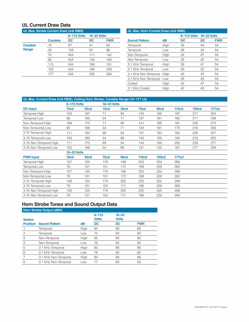
Horn Strobe Output (dBA)
Switch Position Sound Pattern dB
8–17.5 Volts
16–33Volts
DC DC FWR1 Temporal High 84 89 892 Temporal Low 75 83 833 Non-Temporal High 85 90 904 Non-Temporal Low 76 84 845 3.1 KHz Temporal High 83 88 886 3.1 KHz Temporal Low 76 82 827 3.1 KHz Non-Temporal High 84 89 898 3.1 KHz Non-Temporal Low 77 83 83
UL Current Draw Data
Horn Strobe Tones and Sound Output Data
UL Max. Horn Current Draw (mA RMS)
Sound Pattern dB8–17.5 Volts 16–33 VoltsDC DC FWR
Temporal High 39 44 54Temporal Low 28 32 54Non-Temporal High 43 47 54Non-Temporal Low 29 32 543.1 KHz Temporal High 39 41 543.1 KHz Temporal Low 29 32 543.1 KHz Non-Temporal High 42 43 543.1 KHz Non-Temporal Low 28 29 54Coded High 43 47 543.1 KHz Coded High 42 43 54
UL Max. Strobe Current Draw (mA RMS)
Candela8–17.5 Volts 16–33 VoltsDC DC FWR
Candela Range
15 87 41 6030 153 63 8675 N/A 111 14295 N/A 134 164115 N/A 158 191150 N/A 189 228177 N/A 226 264
UL Max. Current Draw (mA RMS), Ceiling Horn Strobe, Candela Range (15–177 cd)
DC Input8–17.5 Volts 16–33 Volts15cd 30cd 15cd 30cd 75cd 95cd 115cd 150cd 177cd
Temporal High 103 167 71 90 143 165 187 217 254Temporal Low 96 165 54 71 137 161 185 211 249Non-Temporal High 106 173 71 90 141 165 187 230 273Non-Temportal Low 95 166 54 71 124 161 170 216 2583.1K Temporal High 111 164 69 94 147 163 184 229 257
3.1K Temporal Low 103 163 54 88 143 155 185 212 2523.1K Non-Temporal High 111 172 69 94 144 164 202 229 2713.1K Non-Temporal Low 103 169 54 88 131 155 187 217 259
FWR Input16–33 Volts15cd 30cd 75cd 95cd 115cd 150cd 177cd
Temporal High 107 135 179 198 223 254 286Temporal Low 78 101 151 172 199 229 262Non-Temporal High 107 135 179 198 223 254 286Non-Temportal Low 78 101 151 172 199 229 2623.1K Temporal High 108 135 179 200 225 255 2893.1K Temporal Low 79 101 150 171 196 229 2603.1K Non-Temporal High 108 135 179 200 225 255 2893.1K Non-Temporal Low 79 101 150 171 196 229 260

3825 Ohio Avenue • St. Charles, IL 60174 Phone: 800-SENSOR2 • Fax: 630-377-6495
©2017 System Sensor.Product specifications subject to change without notice. Visit systemsensor.com
for current product information, including the latest version of this data sheet.AVDS868-02 • 12/01/2017
L-Series Dimensions
Model DescriptionCeiling Horn StrobesPC2RL 2-Wire, Horn Strobe, Red PC2WL 2-Wire, Horn Strobe, WhitePC4RL 4-Wire, Horn Strobe, Red PC4WL 4-Wire, Horn Strobe, White
L-Series Ordering Information
Ceiling-Mount Horn Strobes Ceiling Surface Mount Back Box
Model DescriptionCeiling StrobesSCRL Strobe, RedSCWL Strobe, WhiteSCWL-CLR-ALERT Strobe, White, ALERTAccessoriesTRC-2 Universal Ceiling Trim Ring RedTRC-2W Universal Ceiling Trim Ring WhiteSBBCRL Ceiling Surface Mount Back Box, RedSBBCWL Ceiling Surface Mount Back Box, White
6.83" diam. (173 mm)
2.47" (62.7 mm)
1.37" (34.8 mm) 6.92" diam. (175.77 mm)
2.5"(64 mm)
2-Wire Ceiling Mount Horn Strobes with Ceiling Surface Mount Back Box
4-Wire Ceiling Mount Horn Strobes with Ceiling Surface Mount Back Box
A0531-01
A0545-00 A0546-00
A0494-01
For a ceiling-listed horn-only device, see AVDS865 “Indoor Selectable-Output Horns, Strobes, and Horn Strobes for Wall Applications”.

BRIGHAM YOUNG UNIVERSITY
ADDENDUM RECEIPT
DATE: April 21, 2020
PROJECT: New Dance Studio – RB 273
PROJ. #: K-4194
We acknowledge receipt of Addendum Number 1.
COMPANY:
BY:
TITLE:
PLEASE EMAIL SIGNED RECEIPT TO [email protected]