Brief Operating Instructions Proline Prowirl 72 -...
28
KA00030D/06/EN/14.11 71154534 Brief Operating Instructions Proline Prowirl 72 Vortex Flow Measuring System These Brief Operating Instructions are not intended to replace the Operating Instructions provided in the scope of supply. Detailed information is provided in the Operating Instructions and the additi- onal documentation on the CD-ROM supplied. Depending on the device version, the complete device documenta- tion consists of: Brief Operating Instructions (this document) Operating Instructions Description of Device Functions Approvals and safety certificates Safety instructions in accordance with the approvals for the device (e.g. explosion protection, pressure equipment directive, etc.) Additional device-specific information
Transcript of Brief Operating Instructions Proline Prowirl 72 -...

KA00030D/06/EN/14.11
71154534
Brief Operating Instructions
Proline Prowirl 72Vortex Flow Measuring System
These Brief Operating Instructions are not intended to replace the
Operating Instructions provided in the scope of supply. Detailed
information is provided in the Operating Instructions and the additi-
onal documentation on the CD-ROM supplied.
Depending on the device version, the complete device documenta-
tion consists of:
�Brief Operating Instructions (this document)
�Operating Instructions
�Description of Device Functions
�Approvals and safety certificates
�Safety instructions in accordance with the approvals for the device
(e.g. explosion protection, pressure equipment directive, etc.)
�Additional device-specific information
Proline Prowirl 72
2 Endress+Hauser
Table of contents
1 Safety instructions . . . . . . . . . . . . . . . . . . . . . . . . . . . . . . . . . . . . . 31.1 Designated use . . . . . . . . . . . . . . . . . . . . . . . . . . . . . . . . . . . . . . . . . . . . . . . . . . . . . . . 3
1.2 Installation, commissioning and operation . . . . . . . . . . . . . . . . . . . . . . . . . . . . . . . . . . . 3
1.3 Operational safety . . . . . . . . . . . . . . . . . . . . . . . . . . . . . . . . . . . . . . . . . . . . . . . . . . . . . 3
1.4 Safety conventions . . . . . . . . . . . . . . . . . . . . . . . . . . . . . . . . . . . . . . . . . . . . . . . . . . . . 4
2 Installation . . . . . . . . . . . . . . . . . . . . . . . . . . . . . . . . . . . . . . . . . . 52.1 Transporting to the measuring point . . . . . . . . . . . . . . . . . . . . . . . . . . . . . . . . . . . . . . . 5
2.2 Installation conditions . . . . . . . . . . . . . . . . . . . . . . . . . . . . . . . . . . . . . . . . . . . . . . . . . . 5
2.3 Post-installation . . . . . . . . . . . . . . . . . . . . . . . . . . . . . . . . . . . . . . . . . . . . . . . . . . . . . 10
2.4 Post-installation check . . . . . . . . . . . . . . . . . . . . . . . . . . . . . . . . . . . . . . . . . . . . . . . . . 13
3 Wiring. . . . . . . . . . . . . . . . . . . . . . . . . . . . . . . . . . . . . . . . . . . . . 143.1 Connecting the various housing types . . . . . . . . . . . . . . . . . . . . . . . . . . . . . . . . . . . . . 15
3.2 Special points to note when connecting the transmitter . . . . . . . . . . . . . . . . . . . . . . . 17
3.3 Degree of protection . . . . . . . . . . . . . . . . . . . . . . . . . . . . . . . . . . . . . . . . . . . . . . . . . . 18
3.4 Post-connection check . . . . . . . . . . . . . . . . . . . . . . . . . . . . . . . . . . . . . . . . . . . . . . . . 18
4 Hardware settings . . . . . . . . . . . . . . . . . . . . . . . . . . . . . . . . . . . . 194.1 Device address . . . . . . . . . . . . . . . . . . . . . . . . . . . . . . . . . . . . . . . . . . . . . . . . . . . . . . 19
5 Commissioning . . . . . . . . . . . . . . . . . . . . . . . . . . . . . . . . . . . . . . 215.1 Switching on the measuring device . . . . . . . . . . . . . . . . . . . . . . . . . . . . . . . . . . . . . . 21
5.2 Operation . . . . . . . . . . . . . . . . . . . . . . . . . . . . . . . . . . . . . . . . . . . . . . . . . . . . . . . . . . 22
5.3 Navigating within the function matrix . . . . . . . . . . . . . . . . . . . . . . . . . . . . . . . . . . . . 22
5.4 Calling the Commissioning Quick Setup . . . . . . . . . . . . . . . . . . . . . . . . . . . . . . . . . . 24
5.5 Software settings . . . . . . . . . . . . . . . . . . . . . . . . . . . . . . . . . . . . . . . . . . . . . . . . . . . . 26
5.6 Troubleshooting . . . . . . . . . . . . . . . . . . . . . . . . . . . . . . . . . . . . . . . . . . . . . . . . . . . . . 26
Proline Prowirl 72 Safety instructions
Endress+Hauser 3
1 Safety instructions
1.1 Designated use
�The measuring device is used to measure the volume flow of saturated steam, superheated
steam, gases and liquids. If the process pressure and process temperature are constant, the
measuring device can also output the flow as the calculated mass flow and corrected volume
flow.
�Any use other than that described here compromises the safety of persons and the entire
measuring system and is, therefore, not permitted.
�The manufacturer is not liable for damage caused by improper or non-designated use.
1.2 Installation, commissioning and operation
�The measuring device must only be installed, connected, commissioned and maintained by
qualified and authorized specialists (e.g. electrical technicians) in full compliance with the ins-
tructions in these Brief Operating Instructions, the applicable norms, legal regulations and cer-
tificates (depending on the application).
�The specialists must have read and understood these Brief Operating Instructions and must fol-
low the instructions they contain. If you are unclear on anything in these Brief Operating Ins-
tructions, you must read the Operating Instructions (on the CD-ROM). The Operating Inst-
ructions provide detailed information on the measuring device.
�The measuring device should only be installed in the pipe in a de-energized state free from out-
side loads or strain.
�Repairs may only be performed if a genuine spare parts kit is available and this repair work is
expressly permitted.
�If performing welding work on the piping, the welding unit may not be grounded by means of
the measuring device.
1.3 Operational safety
�The measuring device is designed to meet state-of-the-art safety requirements, has been tested,
and left the factory in a condition in which it is safe to operate. Relevant regulations and Euro-
pean standards have been observed.
�The information specified on the warning notices, nameplates and connection labels fitted on
the measuring device must be observed. These contain important data, including information
on the permitted operating conditions, the application of the measuring device and data on
materials.
�The measuring device must be wired in accordance with the wiring diagrams and connection
labels. Interconnecting must be permitted.
�All parts of the measuring device must be integrated into the potential matching system of the
plant.
�The cables, tested cable glands and tested dummy plugs must suit the prevailing operating con-
ditions, e.g. the temperature range of the process. Housing openings that are not used need
to be sealed with dummy plugs.
Safety instructions Proline Prowirl 72
4 Endress+Hauser
�The measuring device can only be used in conjunction with fluids to which all the wetted parts
of the measuring device are adequately resistant.
With regard to special fluids, including fluids used for cleaning, Endress+Hauser will be happy
to assist in clarifying the corrosion-resistant properties of wetted materials.
However, minor changes in temperature, concentration or in the degree of contamination in
the process may result in variations in corrosion resistance. Unsuitable material can lead to
leakage of corrosive process media and injure personnel and/or cause damage in the plant.
For this reason, Endress+Hauser does not accept any responsibility with regard to the corro-
sion resistance of wetted materials in a specific application. The user is responsible for the
choice of suitable wetted materials in the process.
�Hazardous areas
Measuring devices for use in hazardous areas are labeled accordingly on the nameplate. Rele-
vant national regulations must be observed when operating the device in hazardous areas. The
Ex documentation on the CD-ROM is an integral part of the entire device documentation.
The installation regulations, connection data and safety instructions provided in the Ex docu-
mentation must be observed. The symbol on the front page provides information on the
approval and certification body (0 Europe, 2 USA, 1 Canada). The nameplate also bears
the documentation number of this Ex documentation (XA*****D/../..).
�For measuring systems used in SIL 2 applications, the separate manual on functional safety (on
the CD-ROM) must be observed.
�Hygienic applications
Measuring devices for hygienic applications have their own special labeling. Relevant national
regulations must be observed when using these devices.
�Pressure instruments
Measuring devices for use in systems that need to be monitored are labeled accordingly on the
nameplate. Relevant national regulations must be observed when using these devices. The
documentation on the CD-ROM for pressure instruments in systems that need to be monito-
red is an integral part of the entire device documentation. The installation regulations, con-
nection data and safety instructions provided in the Ex documentation must be observed.
�Endress+Hauser will be happy to assist in clarifying any questions on approvals, their applica-
tion and implementation.
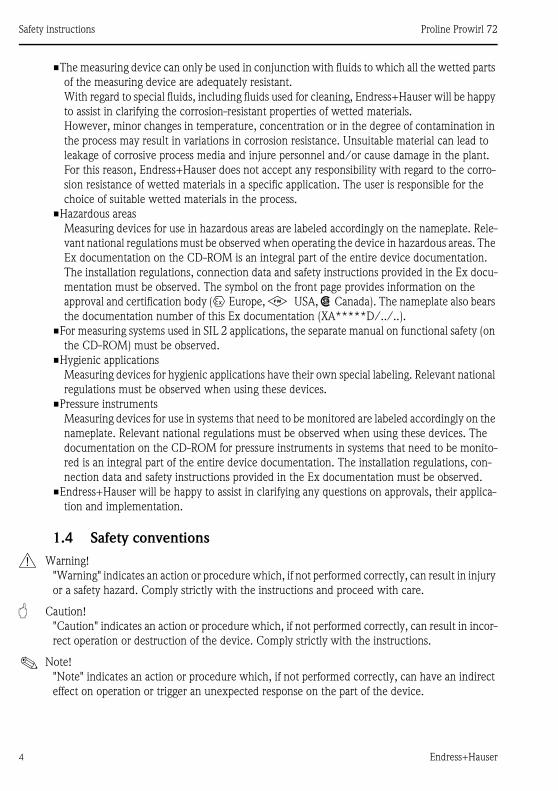
1.4 Safety conventions
# Warning!
"Warning" indicates an action or procedure which, if not performed correctly, can result in injury
or a safety hazard. Comply strictly with the instructions and proceed with care.
" Caution!
"Caution" indicates an action or procedure which, if not performed correctly, can result in incor-
rect operation or destruction of the device. Comply strictly with the instructions.
! Note!
"Note" indicates an action or procedure which, if not performed correctly, can have an indirect
effect on operation or trigger an unexpected response on the part of the device.
Proline Prowirl 72 Installation
Endress+Hauser 5
2 Installation
2.1 Transporting to the measuring point
�Transport the measuring device to the measuring point in the original packaging.
�The covers or caps fitted to the process connections prevent mechanical damage to the sensors
during transportation and storage. For this reason, do not remove the covers or caps until
immediately before installation.
2.2 Installation conditions
It is advisable to support heavy sensors for mechanical reasons (to protect the piping).
2.2.1 Dimensions
For the dimensions of the measuring device, see the associated Technical Information on the
CD-ROM.
2.2.2 Mounting location
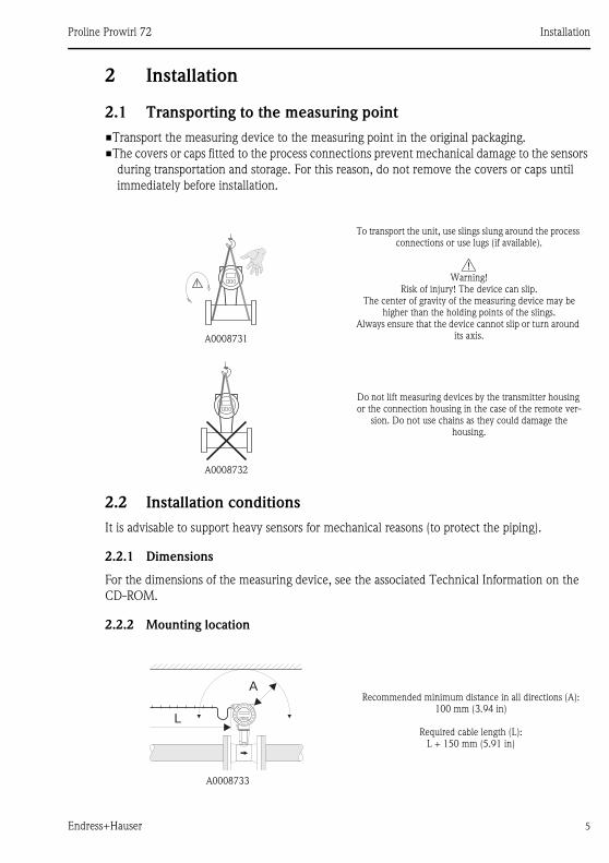
A0008731
To transport the unit, use slings slung around the process connections or use lugs (if available).
#Warning!
Risk of injury! The device can slip.The center of gravity of the measuring device may be
higher than the holding points of the slings.Always ensure that the device cannot slip or turn around
its axis.
A0008732
Do not lift measuring devices by the transmitter housing or the connection housing in the case of the remote ver-
sion. Do not use chains as they could damage the housing.
A0008733
Recommended minimum distance in all directions (A):100 mm (3.94 in)
Required cable length (L): L + 150 mm (5.91 in)
L
A
Installation Proline Prowirl 72
6 Endress+Hauser
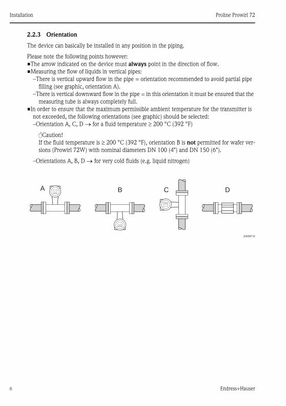
2.2.3 Orientation
The device can basically be installed in any position in the piping.
Please note the following points however:
�The arrow indicated on the device must always point in the direction of flow.
�Measuring the flow of liquids in vertical pipes:
–There is vertical upward flow in the pipe = orientation recommended to avoid partial pipe
filling (see graphic, orientation A).
–There is vertical downward flow in the pipe = in this orientation it must be ensured that the
measuring tube is always completely full.
�In order to ensure that the maximum permissible ambient temperature for the transmitter is
not exceeded, the following orientations (see graphic) should be selected:
–Orientation A, C, D for a fluid temperature 200 °C (392 °F)
"Caution!
If the fluid temperature is 200 °C (392 °F), orientation B is not permitted for wafer ver-
sions (Prowirl 72W) with nominal diameters DN 100 (4") and DN 150 (6").
–Orientations A, B, D for very cold fluids (e.g. liquid nitrogen)
A0008734
A B C D
Proline Prowirl 72 Installation
Endress+Hauser 7
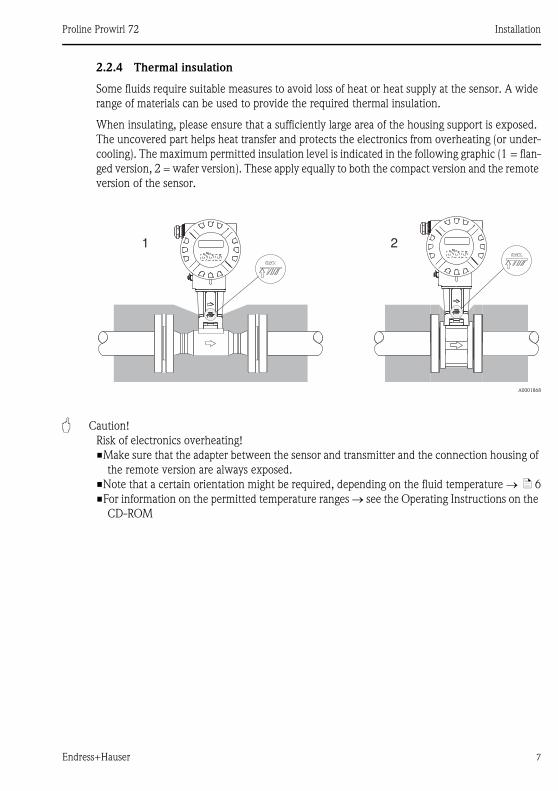
2.2.4 Thermal insulation
Some fluids require suitable measures to avoid loss of heat or heat supply at the sensor. A wide
range of materials can be used to provide the required thermal insulation.
When insulating, please ensure that a sufficiently large area of the housing support is exposed.
The uncovered part helps heat transfer and protects the electronics from overheating (or under-
cooling). The maximum permitted insulation level is indicated in the following graphic (1 = flan-
ged version, 2 = wafer version). These apply equally to both the compact version and the remote
version of the sensor.
A0001868
" Caution!
Risk of electronics overheating!
�Make sure that the adapter between the sensor and transmitter and the connection housing of
the remote version are always exposed.
�Note that a certain orientation might be required, depending on the fluid temperature ä 6
�For information on the permitted temperature ranges see the Operating Instructions on the
CD-ROM
1 2Esc
E- +Esc
E- +
Installation Proline Prowirl 72
8 Endress+Hauser
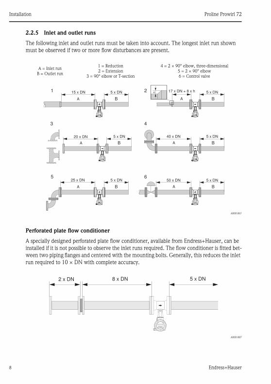
2.2.5 Inlet and outlet runs
The following inlet and outlet runs must be taken into account. The longest inlet run shown
must be observed if two or more flow disturbances are present.
A0001867
Perforated plate flow conditioner
A specially designed perforated plate flow conditioner, available from Endress+Hauser, can be
installed if it is not possible to observe the inlet runs required. The flow conditioner is fitted bet-
ween two piping flanges and centered with the mounting bolts. Generally, this reduces the inlet
run required to 10 × DN with complete accuracy.
A0001887
A = Inlet runB = Outlet run
1 = Reduction2 = Extension
3 = 90° elbow or T-section
4 = 2 × 90° elbow, three-dimensional 5 = 2 × 90° elbow6 = Control valve
15 x DN 5 x DN
A
1
3
5
2
4
6
A
A
A
A
A
B
B
B
B
B
B
17 x DN + 8 x h 5 x DN
20 x DN 5 x DN 40 x DN 5 x DN
25 x DN 5 x DN 50 x DN 5 x DN
h
8 x DN2 x DN 5 x DN
Proline Prowirl 72 Installation
Endress+Hauser 9
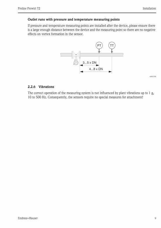
Outlet runs with pressure and temperature measuring points
If pressure and temperature measuring points are installed after the device, please ensure there
is a large enough distance between the device and the measuring point so there are no negative
effects on vortex formation in the sensor.
A0003780
2.2.6 Vibrations
The correct operation of the measuring system is not influenced by plant vibrations up to 1 g,
10 to 500 Hz. Consequently, the sensors require no special measures for attachment!
PT TT
3...5 x DN
4...8 x DN
Esc
E- +
Installation Proline Prowirl 72
10 Endress+Hauser
2.3 Post-installation
2.3.1 Mounting the sensor
" Caution!
�Prior to installing the measuring device in the piping, remove all traces of transport packaging
and any protective covers from the sensor.
�Make sure that the internal diameters of seals are the same as, or greater than, those of the
measuring tube and piping. Seals projecting into the flow current have a negative effect on the
vortex formation after the bluff body and cause inaccurate measurement.
�The direction of the arrow on the measuring tube must match the direction of flow.
�Lengths:
–Prowirl W (wafer version): 65 mm (2.56 in)
–Prowirl F (flanged version) associated Technical Information on CD-ROM
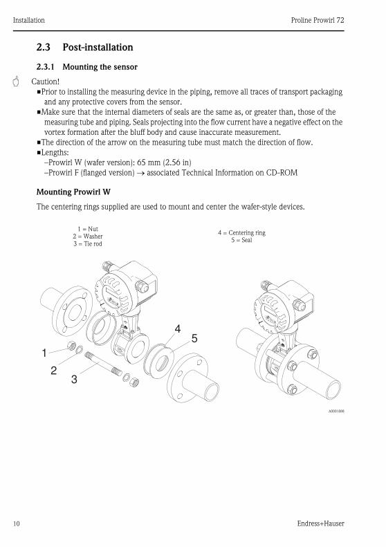
Mounting Prowirl W
The centering rings supplied are used to mount and center the wafer-style devices.
A0001888
1 = Nut2 = Washer3 = Tie rod
4 = Centering ring5 = Seal
1
23
45
Proline Prowirl 72 Installation
Endress+Hauser 11
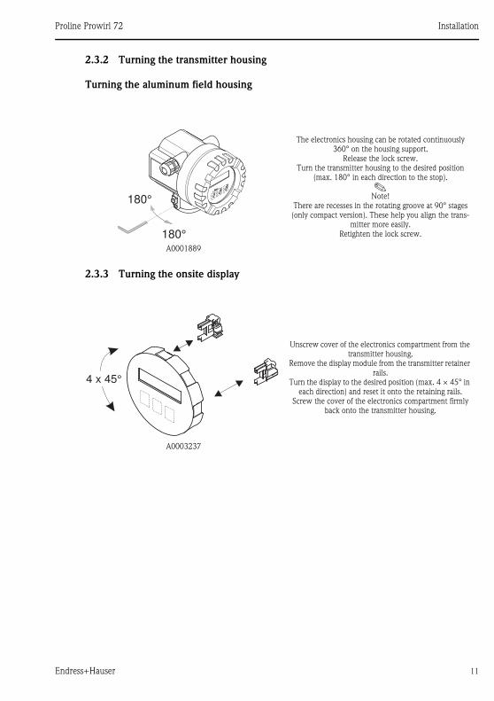
2.3.2 Turning the transmitter housing
Turning the aluminum field housing
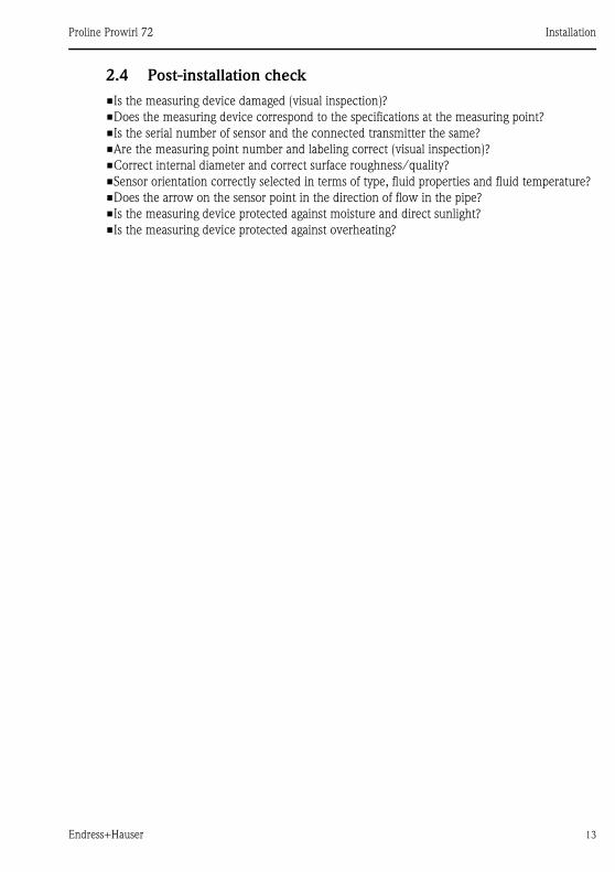
2.3.3 Turning the onsite display
A0001889
The electronics housing can be rotated continuously 360° on the housing support.
Release the lock screw.Turn the transmitter housing to the desired position
(max. 180° in each direction to the stop).
!Note!
There are recesses in the rotating groove at 90° stages (only compact version). These help you align the trans-
mitter more easily.Retighten the lock screw.
A0003237
Unscrew cover of the electronics compartment from the transmitter housing.
Remove the display module from the transmitter retainer rails.
Turn the display to the desired position (max. 4 × 45° in each direction) and reset it onto the retaining rails.
Screw the cover of the electronics compartment firmly back onto the transmitter housing.
180°
180°
4 x 45°

Installation Proline Prowirl 72
12 Endress+Hauser
2.3.4 Mounting the transmitter (remote version)
Mounted directly on the wall
Pipe mounting
A0008735
A0008736
"Caution!
If the device is mounted to a warm pipe, make sure that the housing temperature does not exceed the maximum
permissible value:
Standard:–40 to +80 °C (–40 to +176 °F)
EEx d version:–40 to +60 °C (–40 to +140 °F)
ATEX II 1/2 GD version/dust ignition-proof:–20 to +55 °C (–4 to +131 °F)
ANSCHLUSSKLEMMEN - FIELD TERMINALS
mm (inch)
220 / *214
(8.66 / *8.43)
ANSCHLUSSKLEMMEN - FIELD TERMINALS
Ø 20…70(Ø 0.79…2.75)
mm (inch)
215/ *209
(8.46 / *8.23)
Proline Prowirl 72 Installation
Endress+Hauser 13
2.4 Post-installation check
�Is the measuring device damaged (visual inspection)?
�Does the measuring device correspond to the specifications at the measuring point?
�Is the serial number of sensor and the connected transmitter the same?
�Are the measuring point number and labeling correct (visual inspection)?
�Correct internal diameter and correct surface roughness/quality?
�Sensor orientation correctly selected in terms of type, fluid properties and fluid temperature?
�Does the arrow on the sensor point in the direction of flow in the pipe?
�Is the measuring device protected against moisture and direct sunlight?
�Is the measuring device protected against overheating?
Wiring Proline Prowirl 72
14 Endress+Hauser
3 Wiring
! Note!
�Use a connecting cable with a continuous operation temperature between –40 °C (–40 °F)
and the max. permitted ambient temperature plus 10 °C (plus 18 °F).
�Conductor cross-section: max. 2.5 mm² (14 AWG)
�A shielded connecting cable must be used.
�Route the connecting cable so it is securely seated.
�Pay particular attention to company-internal grounding concepts and national installation regu-
lations and guidelines.
�Seal the cable entries and covers tight.
" Caution!
Risk of damaging the electronic components!
Connect the connecting cable in accordance with the connection data on the nameplate or
the connection data in the Operating Instructions or the Ex documentation on the CD-ROM.
In addition, for the remote version:
" Caution!
Risk of damaging the electronic components!
�Only connect sensors and transmitters with the same serial number.
�The remote version must be grounded. In doing so, the sensor and transmitter must be con-
nected to the same potential matching.
�Observe the cable specifications of the connecting cable Operating Instructions on the
CD-ROM.
! Note!
Install the connecting cable securely to prevent movement.
In addition, for measuring devices with fieldbus communication:
" Caution!
Risk of damaging the electronic components!
�Observe the cable specification of the fieldbus cable Operating Instructions on the
CD-ROM.
�Keep the stripped and twisted lengths of cable shield as short as possible.
�Screen and ground the signal lines Operating Instructions on the CD-ROM.
�If the shielding of the cable is grounded at more than one point in systems without additional
potential equalization, power supply frequency equalization currents can occur that damage
the cable or the shielding. In such instances, the shielding of the cable only has to be grounded
on one side. This means that it may not be connected to the ground terminal of the housing.
The shield that is not connected should be insulated!
Proline Prowirl 72 Wiring
Endress+Hauser 15
In addition, for Ex-certified measuring devices:
# Warning!
When wiring Ex-certified measuring devices, all the safety instructions, wiring diagrams, tech-
nical information, etc. of the related Ex documentation must be observed Ex documentation on the CD-ROM.
3.1 Connecting the various housing types
Wire the unit using the terminal assignment diagram inside the cover.
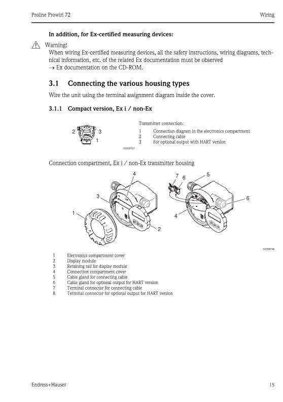
3.1.1 Compact version, Ex i / non-Ex
Connection compartment, Ex i / non-Ex transmitter housing
A0008737
Transmitter connection:
123
Connection diagram in the electronics compartmentConnecting cableFor optional output with HART version
A0008738
12345678
Electronics compartment coverDisplay moduleRetaining rail for display moduleConnection compartment coverCable gland for connecting cableCable gland for optional output for HART versionTerminal connector for connecting cableTerminal connector for optional output for HART version
EscEsc
E- +
1
32
5
6
67
41
3
2
4
Wiring Proline Prowirl 72
16 Endress+Hauser
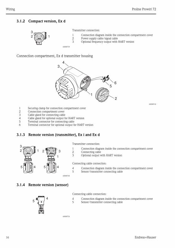
3.1.2 Compact version, Ex d
Connection compartment, Ex d transmitter housing
3.1.3 Remote version (transmitter), Ex i and Ex d
3.1.4 Remote version (sensor)
A0008739
Transmitter connection:
123
Connection diagram inside the connection compartment coverPower supply cable/signal cableOptional frequency output with HART version
A0008742
123456
Securing clamp for connection compartment coverConnection compartment coverCable gland for connecting cableCable gland for optional output for HART versionTerminal connector for connecting cableTerminal connector for optional output for HART version
A0008744
Transmitter connection:
123
Connection diagram inside the connection compartment coverConnecting cableOptional output with HART version
Connecting cable connection:
45
Connection diagram inside the connection compartment coverSensor/transmitter connecting cable
A0008754
Connecting cable connection:
45
Connection diagram inside the connection compartment coverSensor/transmitter connecting cable
EscEsc
E- +
2 1
3
65
21
34
Esc
E- +
1
32Esc
E- +
2 1
3
55 4 4
54
Proline Prowirl 72 Wiring
Endress+Hauser 17
3.2 Special points to note when connecting the transmitter
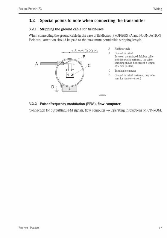
3.2.1 Stripping the ground cable for fieldbuses
When connecting the ground cable in the case of fieldbuses (PROFIBUS PA and FOUNDATION
Fieldbus), attention should be paid to the maximum permissible stripping length.
3.2.2 Pulse/frequency modulation (PFM), flow computer
Connection for outputting PFM signals, flow computer Operating Instructions on CD-ROM.
A0003784
A Fieldbus cable
B Ground terminalBetween the stripped fieldbus cable and the ground terminal, the cable shielding should not exceed a length of 5 mm (0.20 in)
C Terminal connector
D Ground terminal (external, only rele-vant for remote version)
A
D
+ –
1 2
B
C
5 mm (0.20 in)
aaaaaaaaaaaaaaaaaaaaaaaaaaaaaaaaaaaaaaaaaaaaaaaaaaaaaaaaaaaaaaaaaaaaaaaaaaaaaaaaaaaaaaaaaaaaaaaaaaaaaaaaaaaaaaaaaaaaaaaaaaaaaaaaaaaaaaaaaaaaaaaaaaaaaaaaaaaaaaaaaaaaaaaaaaaaaaaaaaaaaaaaaaaaaaaaaaaaaaaaaaaaaaaaaaaaaaaaaaaaaaaaaaaaaaaaaaaaaaaaaaaaaaaaaaaaaaaaaaaaaaaaaaaaaaaaaaaaaaaaaaaaaaaaaaaaaaaaaaaaaaaaaaaaaaaaaaaaaaaaaaaaaaaaaaaaaaaaaaaaaaaaaaaaaaaaaaaaaaaaaaaaaaaaaaaaaaaaaaaaaaaaaaaaaaaaaaaaaaaaaaaaaaaaaaaaaaaaaaaaaaaaaaaaaaaaaaaaaaaaaaaaaaaaaaaaaaaaaaaaaaaaaaaaaaaaaaaaaaaaaaaaaaaaaaaaaaaaaaaaaaaa
�
Wiring Proline Prowirl 72
18 Endress+Hauser
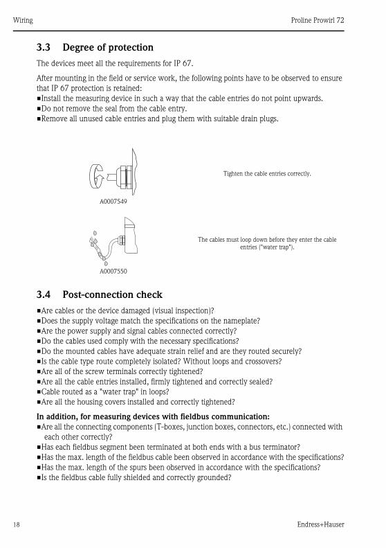
3.3 Degree of protection
The devices meet all the requirements for IP 67.
After mounting in the field or service work, the following points have to be observed to ensure
that IP 67 protection is retained:
�Install the measuring device in such a way that the cable entries do not point upwards.
�Do not remove the seal from the cable entry.
�Remove all unused cable entries and plug them with suitable drain plugs.
3.4 Post-connection check
�Are cables or the device damaged (visual inspection)?
�Does the supply voltage match the specifications on the nameplate?
�Are the power supply and signal cables connected correctly?
�Do the cables used comply with the necessary specifications?
�Do the mounted cables have adequate strain relief and are they routed securely?
�Is the cable type route completely isolated? Without loops and crossovers?
�Are all of the screw terminals correctly tightened?
�Are all the cable entries installed, firmly tightened and correctly sealed?
�Cable routed as a "water trap" in loops?
�Are all the housing covers installed and correctly tightened?
In addition, for measuring devices with fieldbus communication:
�Are all the connecting components (T-boxes, junction boxes, connectors, etc.) connected with
each other correctly?
�Has each fieldbus segment been terminated at both ends with a bus terminator?
�Has the max. length of the fieldbus cable been observed in accordance with the specifications?
�Has the max. length of the spurs been observed in accordance with the specifications?
�Is the fieldbus cable fully shielded and correctly grounded?
A0007549
Tighten the cable entries correctly.
A0007550
The cables must loop down before they enter the cable entries ("water trap").
Proline Prowirl 72 Hardware settings
Endress+Hauser 19
4 Hardware settings
This section only deals with the hardware settings needed for commissioning. All other settings
(e.g. output configuration, write protection, etc.) are described in the associated Operating Ins-
tructions on the CD-ROM.
! Note!
No hardware settings are needed for measuring devices with HART and
FOUNDATION Fieldbus-type communication.
4.1 Device address
Has to be set for measuring devices with the following communication methods:
�PROFIBUS PA
The device address can be configured via:
�Miniature switches see description below
�Device functions/Operating program FieldCare see Operating Instructions on the CD-ROM
Hardware settings Proline Prowirl 72
20 Endress+Hauser
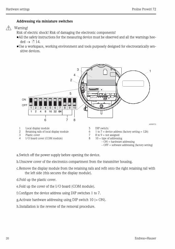
Addressing via miniature switches
# Warning!
Risk of electric shock! Risk of damaging the electronic components!
�All the safety instructions for the measuring device must be observed and all the warnings hee-
ded ä 14.
�Use a workspace, working environment and tools purposely designed for electrostatically sen-
sitive devices.
a.Switch off the power supply before opening the device.
b.Unscrew cover of the electronics compartment from the transmitter housing.
c.Remove the display module from the retaining rails and refit onto the right retaining rail with
the left side (this secures the display module).
d.Fold up the plastic cover.
e.Fold up the cover of the I/O board (COM module).
f.Configure the device address using DIP switches 1 to 7.
g.Activate hardware addressing using DIP switch 10 (= ON).
h.Installation is the reverse of the removal procedure.
A0008755
1234
Local display moduleRetaining rails of local display modulePlastic coverI/O board cover (COM module)
5678
DIP switch:1 to 7 = device address (factory setting = 126)8 to 9 = not assigned10 = type of addressing
– ON = hardware addressing– OFF = software addressing (factory setting)
1
5
2
4
3
76
ON
OFF
8
21 5 6 7 8 9 103 4
21 16 32 64644 8
Proline Prowirl 72 Commissioning
Endress+Hauser 21
5 Commissioning
5.1 Switching on the measuring device
On completion of the installation (successful post-installation check), wiring (successful
post-connection check) and after making the necessary hardware settings, where applicable, the
permitted power supply (see nameplate) can be switched on for the measuring device.
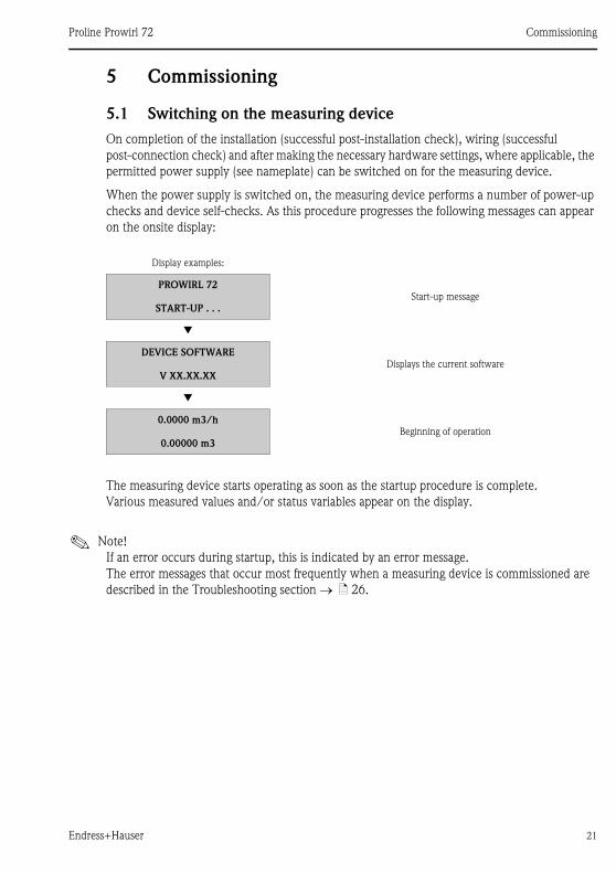
When the power supply is switched on, the measuring device performs a number of power-up
checks and device self-checks. As this procedure progresses the following messages can appear
on the onsite display:
The measuring device starts operating as soon as the startup procedure is complete.
Various measured values and/or status variables appear on the display.
! Note!
If an error occurs during startup, this is indicated by an error message.
The error messages that occur most frequently when a measuring device is commissioned are
described in the Troubleshooting section ä 26.
Display examples:
PROWIRL 72
START-UP . . .Start-up message
Æ
DEVICE SOFTWARE
V XX.XX.XXDisplays the current software
Æ
0.0000 m3/h
0.00000 m3Beginning of operation
Commissioning Proline Prowirl 72
22 Endress+Hauser
5.2 Operation
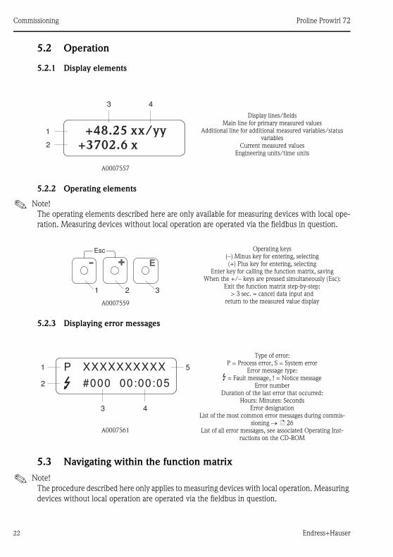
5.2.1 Display elements
5.2.2 Operating elements
! Note!
The operating elements described here are only available for measuring devices with local ope-
ration. Measuring devices without local operation are operated via the fieldbus in question.
5.2.3 Displaying error messages
5.3 Navigating within the function matrix
! Note!
The procedure described here only applies to measuring devices with local operation. Measuring
devices without local operation are operated via the fieldbus in question.
A0007557
Display lines/fieldsMain line for primary measured values
Additional line for additional measured variables/status variables
Current measured values Engineering units/time units
+48.25 xx/yy
+3702.6 x
1
2
3 4
A0007559
Operating keys(–) Minus key for entering, selecting(+) Plus key for entering, selecting
Enter key for calling the function matrix, savingWhen the +/– keys are pressed simultaneously (Esc):
Exit the function matrix step-by-step:> 3 sec. = cancel data input and
return to the measured value display
A0007561
Type of error: P = Process error, S = System error
Error message type:
$ = Fault message, ! = Notice messageError number
Duration of the last error that occurred:Hours: Minutes: Seconds
Error designationList of the most common error messages during commis-
sioning ä 26List of all error messages, see associated Operating Inst-
ructions on the CD-ROM
Esc
E+-
1 2 3
XXXXXXXXXX
#000 00:00:05
P
3 4
2
1 5
Proline Prowirl 72 Commissioning
Endress+Hauser 23
A0007562
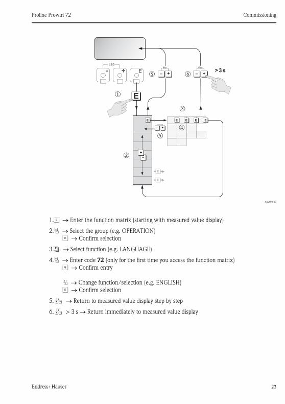
1.F Enter the function matrix (starting with measured value display)
2.P Select the group (e.g. OPERATION)
F Confirm selection
3.NSelect function (e.g. LANGUAGE)
4.P Enter code 72 (only for the first time you access the function matrix)
F Confirm entry
P Change function/selection (e.g. ENGLISH)
F Confirm selection
5.Q Return to measured value display step by step
6.Q > 3 s Return immediately to measured value display
Esc
E+- >3s
E
+
Esc
– +
Esc
–
m
o
n
E
E
–
+
E
+–
E E E E
p
q
q r
Commissioning Proline Prowirl 72
24 Endress+Hauser
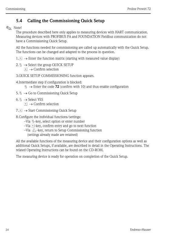
5.4 Calling the Commissioning Quick Setup
! Note!
The procedure described here only applies to measuring devices with HART communication.
Measuring devices with PROFIBUS PA and FOUNDATION Fieldbus communication do not
have a Commissioning Quick Setup.
All the functions needed for commissioning are called up automatically with the Quick Setup.
The functions can be changed and adapted to the process in question.
1.F Enter the function matrix (starting with measured value display)
2.P Select the group QUICK SETUP
F Confirm selection
3.QUICK SETUP COMMISSIONING function appears.
4.Intermediate step if configuration is blocked:
P Enter the code 72 (confirm with 10) and thus enable configuration
5.P Go to Commissioning Quick Setup
6.P Select YES
F Confirm selection
7.F Start Commissioning Quick Setup
8.Configure the individual functions/settings:
–Via P-key, select option or enter number
–Via F-key, confirm entry and go to next function
–Via Q-key, return to Setup Commissioning function
(settings already made are retained)
All the available functions of the measuring device and their configuration options as well as
additional Quick Setups, if available, are described in detail in the Operating Instructions. The
related Operating Instructions can be found on the CD-ROM.
The measuring device is ready for operation on completion of the Quick Setup.

Proline Prowirl 72 Commissioning
Endress+Hauser 25
5.4.1 Flowchart of "Commissioning" Quick Setup
The display returns to the QUICK SETUP COMMISSIONING cell if you press the ESC key com-
bination 10 during interrogation.
Options language, application and measuring variable
Option output type
Only the output (current output or pulse/status output) not yet configured in the current
Quick Setup is offered for selection after the first cycle.
The "YES" option appears as long as a free output is still available. "NO" is the only option dis-
played when no further outputs are available.
QS Commission
Language
Application
Measuring unit type
Volume flow Calculated mass flow Corrected volume flow
Unit flow Unit flow Unit flow
Unit totalizer Unit totalizer Unit totalizer
Unit density Unit density
Operating density Operating density
Reference density
see option output type see option output type
see option output type
Output type
Current output Pulse/Status output Quit
Current span see option operation mode
(Pulse/Status output)
QS Commission
Value 20 mA
Time constant
Failsafe mode
Configurate another output?YES Option output type
NO Automatically configuration display
Commissioning Proline Prowirl 72
26 Endress+Hauser
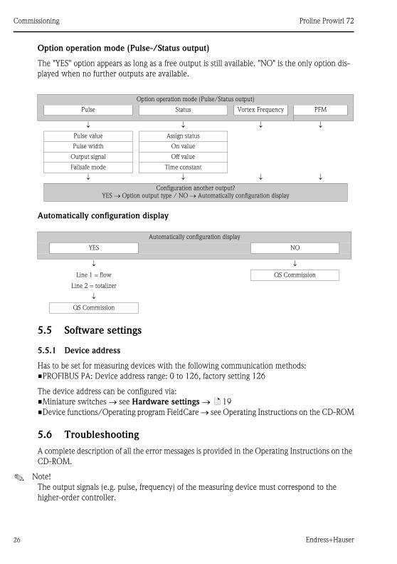
Option operation mode (Pulse-/Status output)
The "YES" option appears as long as a free output is still available. "NO" is the only option dis-
played when no further outputs are available.
Automatically configuration display
5.5 Software settings
5.5.1 Device address
Has to be set for measuring devices with the following communication methods:
�PROFIBUS PA: Device address range: 0 to 126, factory setting 126
The device address can be configured via:
�Miniature switches see Hardware settings ä 19
�Device functions/Operating program FieldCare see Operating Instructions on the CD-ROM
5.6 Troubleshooting
A complete description of all the error messages is provided in the Operating Instructions on the
CD-ROM.
! Note!
The output signals (e.g. pulse, frequency) of the measuring device must correspond to the
higher-order controller.
Option operation mode (Pulse/Status output)
Pulse Status Vortex Frequency PFM
Pulse value Assign status
Pulse width On value
Output signal Off value
Failsafe mode Time constant
Configuration another output?
YES Option output type / NO Automatically configuration display
Automatically configuration display
YES NO
Line 1 = flow QS Commission
Line 2 = totalizer
QS Commission

Proline Prowirl 72 Commissioning
Endress+Hauser 27

KA00030D/06/EN/14.11
71154534
FM+SGML 9.0