Brief Introduction For Micro Water Power...
19
Neweras Develop Limited Contact: Mr. Jack Chen MP: 86 15002143331 Skype: chysir Email: [email protected] Web: ww.newerasdevelop.com Address: Room 808, No.45, East Yanan Road, Shanghai, China 1/19 Brief Introduction For Micro Water Power Generator 1. Primary knowledge for common water power plant 1.1 Summarization for water power generating Energy source for power generating is various such as water power, solar energy, wind power, and etc. Water power generating has advantages of low cost and no pollution. And the hydropower plant can be built together with other irrigation works. Water source is easy to get in most counties and regions of the world. Water power generating will play a more and more important role in the future. Water level of a river’s upper stream is higher than its down stream. This water level difference brings water power. This energy is called potential energy. The water level difference is called water head. Water head is basic condition for water power. Furthermore, water power depends on flow rate of the river also. The higher water head and flow rate give bigger power output. Surface slope is a ratio of water head against distance. It is used to show concentration ratio of water head. The bigger surface slope, water power is easier to be used. Flow rate is water quantity flows during unit time. It is denoted by how many cubic meters of water flow through in one second. Flow rate of a river varies from time to time and location to location, so we should determine a concrete location and time when we talk about flow rate of a river. In China, flow rate of river is generally big in summer and autumn, but small in spring and winter; and different in each year, each month, even each day. In addition, flow rate of a river is small in upper stream, and increases in down stream for the sake of branches collection. In general, water head concentrates in upper stream, but flow rate is relatively small there. While water head
Transcript of Brief Introduction For Micro Water Power...
Neweras Develop Limited Contact: Mr. Jack Chen MP: 86 15002143331 Skype: chysir Email: [email protected] Web: ww.newerasdevelop.com Address: Room 808, No.45, East Yanan Road, Shanghai, China
1/19
Brief Introduction For Micro Water Power Generator
1. Primary knowledge for common water power plant 1.1 Summarization for water power generating
Energy source for power generating is various such as water power, solar
energy, wind power, and etc. Water power generating has advantages of low
cost and no pollution. And the hydropower plant can be built together with
other irrigation works. Water source is easy to get in most counties and regions
of the world. Water power generating will play a more and more important role
in the future.
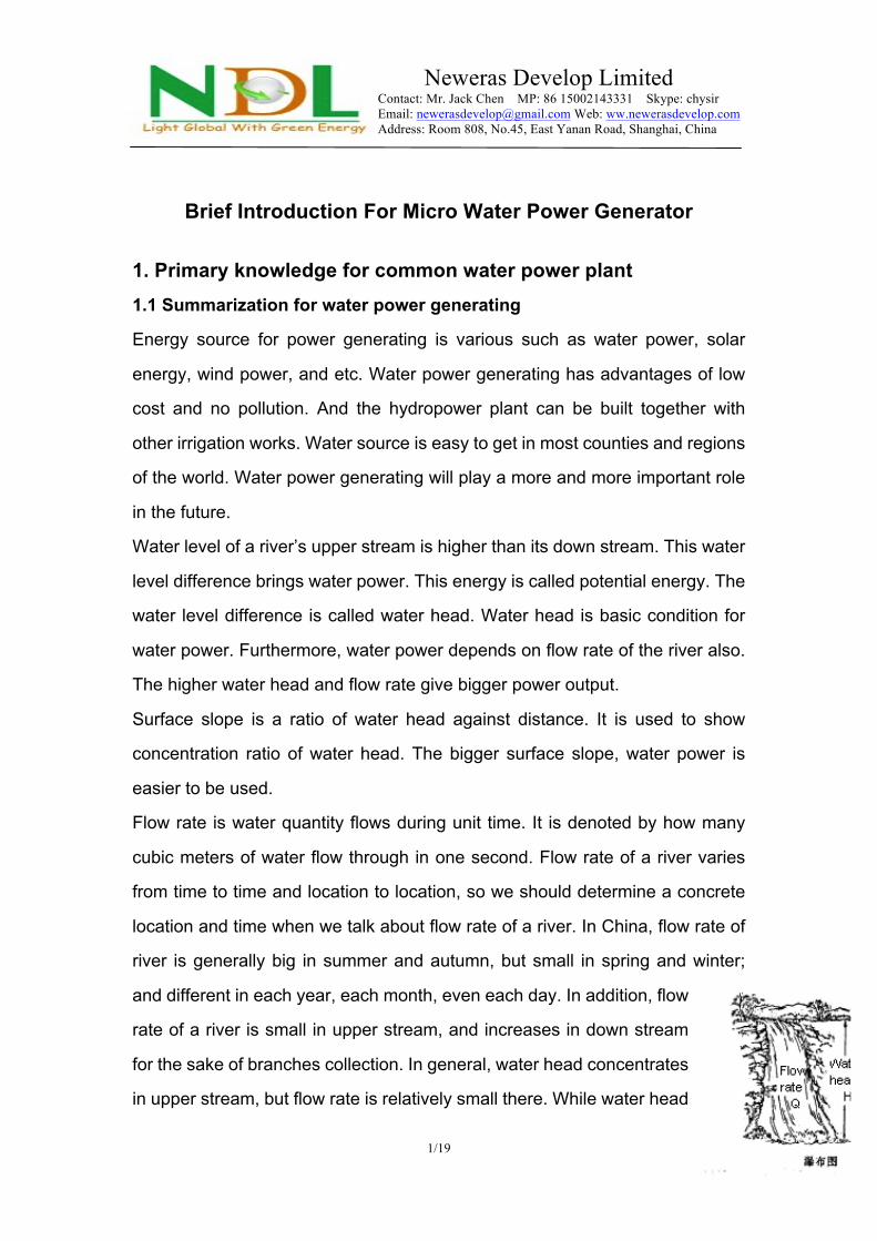
Water level of a river’s upper stream is higher than its down stream. This water
level difference brings water power. This energy is called potential energy. The
water level difference is called water head. Water head is basic condition for
water power. Furthermore, water power depends on flow rate of the river also.
The higher water head and flow rate give bigger power output.
Surface slope is a ratio of water head against distance. It is used to show
concentration ratio of water head. The bigger surface slope, water power is
easier to be used.
Flow rate is water quantity flows during unit time. It is denoted by how many
cubic meters of water flow through in one second. Flow rate of a river varies
from time to time and location to location, so we should determine a concrete
location and time when we talk about flow rate of a river. In China, flow rate of
river is generally big in summer and autumn, but small in spring and winter;
and different in each year, each month, even each day. In addition, flow
rate of a river is small in upper stream, and increases in down stream
for the sake of branches collection. In general, water head concentrates
in upper stream, but flow rate is relatively small there. While water head

Neweras Develop Limited Contact: Mr. Jack Chen MP: 86 15002143331 Skype: chysir Email: [email protected] Web: ww.newerasdevelop.com Address: Room 808, No.45, East Yanan Road, Shanghai, China
2/19
disperses in down stream though there is big flow rate. Therefore, it is most
economical to use water power in middle reaches of a river.
Power output of a water power plant can be calculated by the following
formula.
N = G * Q * H * K N: Power output (KW) Q: Flow rate (m3/s) H: Water head (m) G = 9.8 , acceleration of gravity (Newton/kg) K: Efficiency of the water power plant (About 0.5 ~ 0.6)
1.2. Component parts of water power plant
Water power plant consists of hydraulic architecture, mechanical device and
electrical device.
1.2.1 Hydraulic architecture
It consists of dam, water entrance gate, channel, front pressure pool (or
equalizing pond), pressure conduit, plant workshop and tailrace.
Raise water level to get a reservoir by building a dam in river. Thus a
concentrated water head
between water level in reservoir
and river after dam is available.
Then the water can be led to
water power plant by channel.
Or diversion type water power
plant as shown in the following
picture can be used in steep
river.
1.2.2 Water power device

Neweras Develop Limited Contact: Mr. Jack Chen MP: 86 15002143331 Skype: chysir Email: [email protected] Web: ww.newerasdevelop.com Address: Room 808, No.45, East Yanan Road, Shanghai, China
3/19
The following devices are necessary for water power plant besides the above
mentioned hydraulic architecture.
Mechanical device: Turbine, governor, gate valve, driving device and other
equipment.
Electrical device: Generator, power distributor, transformer and power
transmission line.
2 Primary knowledge for micro water power plant 2.1 Summarization for micro water power plant
Most areas without power supply are backward countryside and far away from
electric network. 10KV Power transmission line costs about USD8000.00 each
kilometer. And the transmission distance should be less than 20 kilometers. It
is uneconomical and unpractical to use traditional main power supply network.
But if there is small water source available in these areas, micro water power
generator can solve the problem economically.
To make use of small brooks, small raceway or small waterfall for power
generating will save the cost of power transmission line, and solve the problem
of power supply for remote households.
The working principle of micro water power plant is similar with big water
power plant. Micro water power generator generally means the generator with
installed capacity below 100KW. It is suitable to be used in countryside with
small water source. The micro water power generator has the following
advantages.
1). Small capacity: Micro water power plant is suitable to be built and used
dispersedly, especially for use of mountainous or hill area
2). Small investment: Investment for micro water power plant is small. Users
can invest,build and manage by themselves.
Neweras Develop Limited Contact: Mr. Jack Chen MP: 86 15002143331 Skype: chysir Email: [email protected] Web: ww.newerasdevelop.com Address: Room 808, No.45, East Yanan Road, Shanghai, China
4/19
3). Short construction period: Micro water power plant can be finished
construction and put into use in a short time.
4). Zero working and maintenance cost: Micro water power plant uses water as
energy source. No fuel and spare parts are necessary.
5). Easy to use, build and popularization.
2.2 Conformation of micro water turbine
According to conformation and flow direction of water, water turbine can be
divided into many types. Micro water power generator set is divided into
impulse type and reaction type.
Pelton type, inclined jet type and Banki type belong to impulse type turbine,
and axial flow type and Francis type belong to reaction type turbine.
We will introduce some common types of micro water power generator used in
countryside.
Impulse type turbine makes a strong jet stream by nozzle to drive turbine
runner. Reaction type makes use of water pressure difference between front
and reverse side of vanes. The pressure difference drives runner to apply
work.
Turbine plays a very important role in micro water power generator set. It
should be chosen, installed, managed and maintained correctly.
2.2.1 Conformation of impulse type turbine
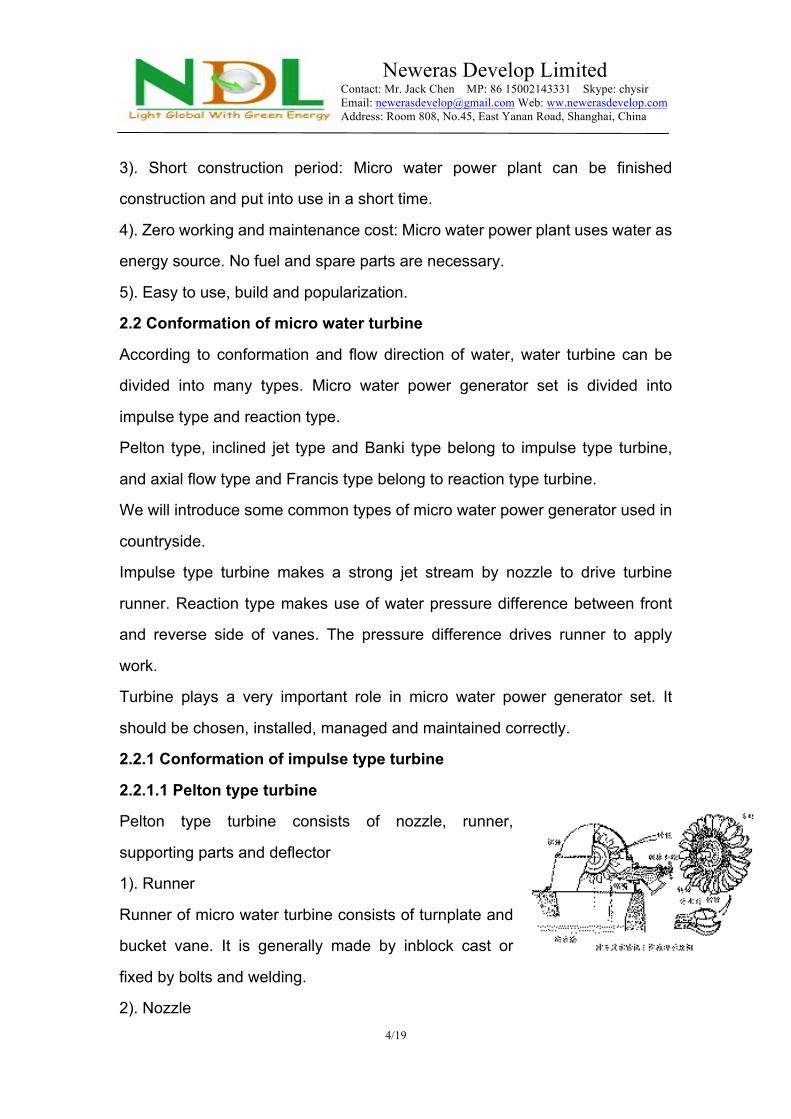
2.2.1.1 Pelton type turbine
Pelton type turbine consists of nozzle, runner,
supporting parts and deflector
1). Runner
Runner of micro water turbine consists of turnplate and
bucket vane. It is generally made by inblock cast or
fixed by bolts and welding.
2). Nozzle
Neweras Develop Limited Contact: Mr. Jack Chen MP: 86 15002143331 Skype: chysir Email: [email protected] Web: ww.newerasdevelop.com Address: Room 808, No.45, East Yanan Road, Shanghai, China
5/19
Nozzle consists of nozzle body and adjusting needle. Its main function is to
make and shoot strong jet stream to water bucket from best direction.
Adjusting needle is used to adjust flow rate. It has the function of water
distributor. In general, only one nozzle is equipped for turbine, but when flow
rate is enough, nozzle quantities can be increased.
Pelton type turbine is suitable for conditions of big water head and small flow
rate.
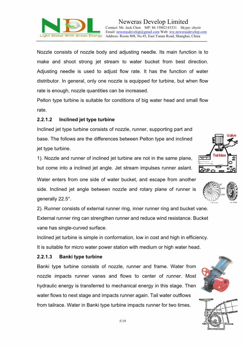
2.2.1.2 Inclined jet type turbine
Inclined jet type turbine consists of nozzle, runner, supporting part and
base. The follows are the differences between Pelton type and inclined
jet type turbine.
1). Nozzle and runner of inclined jet turbine are not in the same plane,
but come into a inclined jet angle. Jet stream impulses runner aslant.
Water enters from one side of water bucket, and escape from another
side. Inclined jet angle between nozzle and rotary plane of runner is
generally 22.5°.
2). Runner consists of external runner ring, inner runner ring and bucket vane.
External runner ring can strengthen runner and reduce wind resistance. Bucket
vane has single-curved surface.
Inclined jet turbine is simple in conformation, low in cost and high in efficiency.
It is suitable for micro water power station with medium or high water head.
2.2.1.3 Banki type turbine
Banki type turbine consists of nozzle, runner and frame. Water from
nozzle impacts runner vanes and flows to center of runner. Most
hydraulic energy is transferred to mechanical energy in this stage. Then
water flows to next stage and impacts runner again. Tail water outflows
from tailrace. Water in Banki type turbine impacts runner for two times.

Neweras Develop Limited Contact: Mr. Jack Chen MP: 86 15002143331 Skype: chysir Email: [email protected] Web: ww.newerasdevelop.com Address: Room 808, No.45, East Yanan Road, Shanghai, China
6/19
It is suitable for conditions of medium or low water head.
2.2.2 Conformation of reaction type turbine
2.2.2.1 Francis type turbine
Conformation of Francis type turbine is shown in the picture. Water enters
runner radially, and leaves axially. Francis type turbine is divided into vertical
type and horizontal type. In general, vertical type is often used in
micro water power station.
Francis type turbine is suitable for water power station with
medium or low water head and flow rate. It consists of water
guiding chamber, runner, water distributor and draft tube.
Functions and conformations of these parts are introduced as
follows.
2.2.2.1.1 Water guiding chamber
There are metal spiral case and metal tank two types of water guiding chamber
are generally used. Its main function is to guarantee water enters water
distributor evenly and symmetrically in order to reduce loss of water head.
Spiral case is the best choice for turbine behavior. Advantages of metal tank
type is simple in conformation and low in cost, but loss of water head is bigger
than spiral case. So it is generally used in small turbine.
2.2.2.1.2 Runner
Runner is key part of turbine. Hydraulic energy is transferred to
mechanical energy by runner. Runner of Francis turbine
consists of vanes, runner hub and torus. Radial water flow is
changed to axial flow by vanes. Quantity of vanes can be 10 to
24 pieces. Usual quantity is 14 to 17 pieces.
Vanes, runner hub and torus can be made by inblock cast, or
by separate cast and welding.
2.2.2.1.3 Water distributor

Neweras Develop Limited Contact: Mr. Jack Chen MP: 86 15002143331 Skype: chysir Email: [email protected] Web: ww.newerasdevelop.com Address: Room 808, No.45, East Yanan Road, Shanghai, China
7/19
Water distributor has the following function.
Guide water enters runner from best direction.
Adjust flow rate of water in runner to fit outside load change.
For start or stop of generator set.
2.2.2.2 Axial flow type turbine
Water enters runner of axial flow turbine axially, and leaves axially also. It is
suitable for conditions of low water head and big flow rate.
The same as Francis turbine, axial flow turbine also consists of water guiding
chamber, runner, water distributor and draft tube. All parts are similar to those
of Francis turbine except runner. In order to meet requests of big flux, there are
only 3 to 8 vanes are equipped for runner of axial flow turbine. Vanes of small
runner are generally fixed, but in order to improve efficiency and working
conditions, sometimes adjustable vanes are equipped for turbine runner of
some water power stations whose water head and flow rate vary seasonally.
2.3 Conformation of generator
Generators used in micro water power generator set are divided into two types,
namely synchronous generator and asynchronous generator. At present, most
generators are synchronouse type. Only few micro water power stations with
small capacity choose asynchronous generator. Herein we only introduce
synchronous generator.
Synchronous generator is divided into two types. One type is traditional
excitation synchronous generator with rotor shaft of excitation winding, slip ring
and excitation device. Another type is magneto synchronouse generator
whose rotor is made of permanent magnet material. In addition, generator can
be also divided into single-phase generator and three-phase generator. Power
output of single-phase generator is generally below 15KW. Three-phase
generator is high in efficiency. Generators wth big capacity are all three-phase
type.

Neweras Develop Limited Contact: Mr. Jack Chen MP: 86 15002143331 Skype: chysir Email: [email protected] Web: ww.newerasdevelop.com Address: Room 808, No.45, East Yanan Road, Shanghai, China
8/19
2.3.1 Conformation of traditional synchronous alternator
Main parts of excitation synchronous alternator are stator, rotor, end closure
and excitation device. Friction parts such as slip ring and carbon brush should
be replaced regular. Elements of rectifier of excitation device are easy to be
damaged. Spare parts should be prepared.
2.3.2 Magneto synchronous alternator
Operational principle of magneto synchronous alternator is the same with
traditional synchronous alternator, but rotor of magneto synchronous alternator
is made of permanent magnet material. No pole coil, slip ring and excitation
device are necessary. Reliability is improved in a great deal. Power of magneto
synchronous alternator can reach 30KW. Cost of magneto synchronous
alternator is higher than common one, but it is more suitable for remote
countryside for its high reliability. 3. Construction for micro water power station 3.1 Preparation for turbine type choice
3.1.1 Choice of water source
As we mentioned in the first chapter, there are two basic conditions are
necessary for micro water power generator. Namely water and water head.
1). Try to find river, brook or spring with natural gradient as water source.
Water source should be permanent. Record flow rate in dry season and flood
season as reference for option of turbine type.
Neweras Develop Limited Contact: Mr. Jack Chen MP: 86 15002143331 Skype: chysir Email: [email protected] Web: ww.newerasdevelop.com Address: Room 808, No.45, East Yanan Road, Shanghai, China
9/19
2). If natural gradient is available, investment for hydraulic architecture is much
smaller. Then invester can build a water pool on the spot, and connect the
pressure water pipe to turbine for power generating. If no natural gradient, try
to dig a raceway along the hillside to lead the water to a location downriver
where can make gradient artificially. Build a forebay here for water storage.
3.1.2 Measurement for water head
After finding water source and suitable location for power station, the next step
is measurement for water head. There are a lot of methods for water head
measurement. Herein we only introduce one simpliest method by hydraulic
pressure cathetometer. Hydraulic pressure cathetometer consists of pressure
gauge and 20 meters of transparent plastic pipe. When the plastic pipe is full of
water, pressure difference of pipe’s two sides will be shown in the pressure
gauge. Relative water head can be determined from the following form by the
pressure difference.
Pressure shown in gauge (MPa) 0.04 0.08 0.12 0.16
Water head (m) 4 8 12 16
Tool: Hydraulic pressure cathetometer, ribbon tape, wooden pole, notebook
and pen.
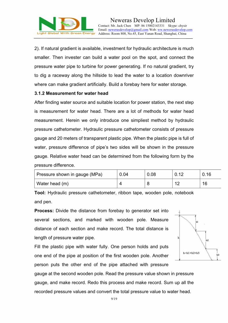
Process: Divide the distance from forebay to generator set into
several sections, and marked with wooden pole. Measure
distance of each section and make record. The total distance is
length of pressure water pipe.
Fill the plastic pipe with water fully. One person holds and puts
one end of the pipe at position of the first wooden pole. Another
person puts the other end of the pipe attached with pressure
gauge at the second wooden pole. Read the pressure value shown in pressure
gauge, and make record. Redo this process and make record. Sum up all the
recorded pressure values and convert the total pressure value to water head.

Neweras Develop Limited Contact: Mr. Jack Chen MP: 86 15002143331 Skype: chysir Email: [email protected] Web: ww.newerasdevelop.com Address: Room 808, No.45, East Yanan Road, Shanghai, China
10/19
Note: No air should remaines in the pipe.
3.1.3 Measurement for flow rate
3.1.3.1 Container method
Water flow of micro water power station is generally small. Generator sets for
big water head and small flow rate are frequently used. Container method for
measurement of flow rate is suitable for this condition and easy to operate.
Tool: One barrel, one stopwatch, notebook and pen.
Process:
1). Measure how many liters water can be held in the barrel by weighing
(Supposing volume of 1KG water is 1 liter).
2). Collect water from one outlet.
3). Check in how many seconds the barrel is filled up by stopwatch. Redo this
for three times to get the average value.
4). Formula for flow rate:
Flow rate (L/S) = Volume of barrel (L) / Time for filling up one barrel (S)
3.1.3.2 Method by average measurement of channel
Method by average measurement of channel can be carried out when flow rate
is big.
1). Choose one straight segment in the channel. There should be no marked
changes in width and depth in this segment. This segment should be at least
10 meters long. The longer in length, the accurater in measurement result.
2). Set two cross sections in both ends of the channel
segment, and mark these two cross sections with
wooden poles. Measure distance between these two
wooden poles.
3). Figure out sectional area by depth of water and
width of channel.
Sectional area of rectangular channel = Width of channel × Depth of water

Neweras Develop Limited Contact: Mr. Jack Chen MP: 86 15002143331 Skype: chysir Email: [email protected] Web: ww.newerasdevelop.com Address: Room 808, No.45, East Yanan Road, Shanghai, China
11/19
Sectional area of trapeziform channel
= (Width of water surface + Width of channel bottom) / 2 × Depth of water
4). Put a drogue in the channel. Measure time required for the drogue passing
these two wooden poles by stopwatch. Redo this process for 3 to 5 times, and
figure out the average time. Divide the distance between two wooden poles by
the average time gets velocity of the water flow.
5). Multiply the average velocity of flow by sectional area of the channel gets
flow rate.
3.2 Hydraulic architecture
After getting the necessary data of flow rate and water head, turbine type can
be determined accordingly. As the next step, design for hydraulic architecture
should be carried out.
Hydraulic architecture of micro water power station consists of dam or weir,
water entrance gate, channel, pressure forebay, pressure conduit, workshop
and tailrace.
3.2.1 Dam (Weir)
Dam (weir) blocks river and raise water level. In general, dam (weir) is built in
upper stream in order to make use of the water head completely. Thus dam
(weir) can be lower in height, and the construction cost can be reduced
accordingly.
3.2.2 Water entrance gate
Functions of water entrance gate are to control flow rate in channel and to
ward off water when examine or repair channel and pressure forebay.
3.2.3 Channel
Channel leads water from water entrance gate to forebay. Because of its
gentle longitudinal gradient, channel can concentrate enough water head for
power generating.
3.2.3.1 Cross section shape of channel

Neweras Develop Limited Contact: Mr. Jack Chen MP: 86 15002143331 Skype: chysir Email: [email protected] Web: ww.newerasdevelop.com Address: Room 808, No.45, East Yanan Road, Shanghai, China
12/19
Cross section shape of channel is divided into trapezium (On soil matrix) and
rectangle (On batholith) according to different geological conditions.
3.2.3.2 Route choice of channel
Route choice of channel should guarantee convenient construction, small work
amount, biggest water head available and to get dual-purpose of irrigation for
farmland. In detail, route choice of channel should be accordance with the
following principles.
1). Short in distance.
2). Try to build channel on high in order to get big water head, and the
geological conditions should be good enough.
3). Try to reduce work amount, and avoid sharp turning. Turning radius of
channel should be not less than 5 times of water surface width.
4). Try to keep the channel away from road, mountain trench or bottom land in
order to save the investment for flume or inverted siphon culvert.
3.2.3.3 Determining for longitudinal gradient of channel
Channel should have longitudinal gradient from the beginning to the end to
guarantee smooth flowing of water.
Altitude difference of beginning and end of channel (m) Longitudinal gradient = Horizontal distance between beginning and end of channel (m)
When choosing longitudinal gradient of channel, the following factors should
be taken into account.
1). When longitudinal gradient of channel is too big, flow velocity of water in
channel is high. Loss of water head is big though small sectional area of
channel is acceptable. The big water head loss causes smaller power output.
And high flow velocity brings quick erosion of channel.
Neweras Develop Limited Contact: Mr. Jack Chen MP: 86 15002143331 Skype: chysir Email: [email protected] Web: ww.newerasdevelop.com Address: Room 808, No.45, East Yanan Road, Shanghai, China
13/19
2). On the other side, if longitudinal gradient of channel is too small, flow
velocity of water in channel is low. Silt is easy to deposite. In addition, sectional
area of channel should be big enough. This causes big work amount in
construction.
Therefore, longitudinal gradient should not be too big or too small, but should
be designed according to earth conditions. If water head is enough,
longitudinal gradient can be bigger to reduce sectional area of channel and
work amount of construction. In area with small water head, longitudinal
gradient can be smaller. In general, longitudinal gradient of channel of micro
water power station should be between 1/500 to 1/3000.
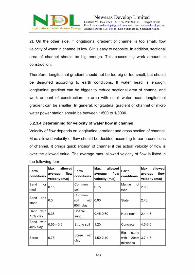
3.2.3.4 Determining for velocity of water flow in channel
Velocity of flow depends on longitudinal gradient and cross section of channel.
Max. allowed velocity of flow should be decided according to earth conditions
of channel. It brings quick erosion of channel if the actual velocity of flow is
over the allowed value. The average max. allowed velocity of flow is listed in
the following form.
Earth conditions
Max. allowed average flow velocity (m/s)
Earth conditions
Max. allowed average flow velocity (m/s)
Earth conditions
Max. allowed average flow velocity (m/s)
Sand or mud 0.15 Common
soil 0.75 Mantle of rock 2.00
Sand and stone 0.3
Common soil with 65% clay
0.90 Slate 2.40
Sand with 15% clay 0.35 Coarse
sand 0.45-0.60 Hard rock 2.4-4.5
Sand with 40% clay 0.55-0.6 Strong soil 1.20 Concrete 4.5-6.0
Scree 0.75 Scree with clay 1.50-2.10
Big stone with 20cm thickness
3.7-4.3

Neweras Develop Limited Contact: Mr. Jack Chen MP: 86 15002143331 Skype: chysir Email: [email protected] Web: ww.newerasdevelop.com Address: Room 808, No.45, East Yanan Road, Shanghai, China
14/19
In actual situation, velocity of flow should not be lower than 0.4m/s in order to
avoid deposition of sand and soil. Grass cannot grow in soil channel when
velocity of flow is over 0.75m/s. But when velocity of flow is below 0.5m/s,
grass grows quickly. Therefore, average velocity of flow in soil channel should
be between 0.5m/s to 0.8m/s. If this value is over the max. allowed average
flow velocity listed in above form, values in form should be regarded as
adopted standard.
3.2.3.5 Washing and drainage facility of channel
When channel encircles hill, rain water from the hill drops in the
channel, so overflow chutes or water drainage gate should be
furnished in suitable positions. In addition, sandbasins should be set
in channel with certain intervals. Water drainage gate has also sand
washing function.
3.2.4 Pressure forebay
Pressure forebay is a pool which connects channel and
pressure conduit. It plays a very important role in micro
water power station. Pressure forebay consists of water
reservoir, trash rack, water gate and overfall gap. Its
functions are as follows.
1). Lead water from channel into pressure conduit. If the water power station is
equipped with several generator sets, pressure forebay can be used to
distribute water for each generator set through several pressure conduits.
2). Trash rack is furnished for forebay to prevent pressure conduit and turbine
from being blocked by root, weeds, sand , mud or freezing.
3). Avoid water entering pressure conduit when maintenance of pressure
conduit or turbine.
4). Pressure forebay has function of adjustment for water quantity
momentarily.
Neweras Develop Limited Contact: Mr. Jack Chen MP: 86 15002143331 Skype: chysir Email: [email protected] Web: ww.newerasdevelop.com Address: Room 808, No.45, East Yanan Road, Shanghai, China
15/19
5). Discharge redundant water by overfall gap to keep stable water head in
pressure forebay.
6). Release abrasion of turbine by depositing sand and soil in forebay.
Recommended size of pressure forebay:
1. Impulse type generator set below 750W can be furnished with a simple
forebay with overfall gap. Dimensions of forebay can be 80 x 80 x 80 cm.
2. Pressure forbay of impulse type generator set from 1000W to 3000W should
be built by concrete. Volume of forebay should be over 1 m3.
3. Pressure forbay of impulse type generator set from 4000W to 10000W
should be built by concrete. Depth is about 120 cm; width about 100 cm; and
length about 150 to 200 cm.
3.2.5 Overfall gap
Redundant water in pressure forebay can be exhausted by overfall gap. The
overfall gap is generally set on the side face of forebay.
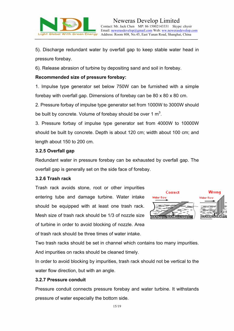
3.2.6 Trash rack
Trash rack avoids stone, root or other impurities
entering tube and damage turbine. Water intake
should be equipped with at least one trash rack.
Mesh size of trash rack should be 1/3 of nozzle size
of turbine in order to avoid blocking of nozzle. Area
of trash rack should be three times of water intake.
Two trash racks should be set in channel which contains too many impurities.
And impurities on racks should be cleaned timely.
In order to avoid blocking by impurities, trash rack should not be vertical to the
water flow direction, but with an angle.
3.2.7 Pressure conduit
Pressure conduit connects pressure forebay and water turbine. It withstands
pressure of water especially the bottom side.
Neweras Develop Limited Contact: Mr. Jack Chen MP: 86 15002143331 Skype: chysir Email: [email protected] Web: ww.newerasdevelop.com Address: Room 808, No.45, East Yanan Road, Shanghai, China
16/19
3.2.7.1 Choice of diameter of pressure conduit
Diameter of pressure conduit depends on flow velocity of water in conduit,
water head loss, project investment, constructing and maintenance. Too small
diameter of choosen pipe makes higher water head loss and lower power
output though investment on pressure conduit is smaller. On the other hand,
too big pipe diameter reduces water head loss, but increases investment on
pressure conduit.
Choice of diameter of pressure conduit should be accordance with data offered
by manufacturer or by calculation. When water head is below 20 meters,
calculated flow velocity in conduit should be less than 1.5 m/s. And when water
head is over 30 meters, flow velocity should be less than 2 m/s.
Calculation formula: Flow velocity (V) = Flow rate (Q) ÷ Section area of pipe
(S)
Plastic pipe can be used as pressure conduit of micro water power plant below
1 KW. Pressure withstanding capacity of plastic pipe is below 3.5 kg, so the
water head should be below 35 meters. Try to install plastic pipe underground
in order to avoid aging. Life of plastic pipe can be prolonged to over 10 years
by this way. Water power generator set over 2 KW should be equipped with
steel pipe as pressure conduit.
3.2.7.2 Water-hammer pressure
Close valve on bottom side of pressure conduit suddenly when water flows
smoothly in pipe. Water-hammer pressure caused by inertia of water is
possibly to burst the pipe. Therefore, water-hammer pressure should be taken
into account when designing pressure conduit, and do not close valve quickly.
3.2.7.3 Choice of pipe
Necessary withstanding pressure of pipe depends on water head. Pressure of
water is 1 kg force each 10 meters water head. Plastic pipe can withstand 3 to

Neweras Develop Limited Contact: Mr. Jack Chen MP: 86 15002143331 Skype: chysir Email: [email protected] Web: ww.newerasdevelop.com Address: Room 808, No.45, East Yanan Road, Shanghai, China
17/19
5 kg, and steel pipe can withstand 10 to 20 kg. Besides pressure of water head,
water-hammer pressure should be taken into account when choose pipe.
3.2.7.4 Function of expansion joint
Expansion joint is furnished in order to reduce stress and distortion of pipe
caused by variety of temperature. Expansion joint is generally set at upper side
of each section of pipe because water pressure is the lowest at this position. If
the total length of pipe is less than 24 meters (Each section is 3 meters long.),
expansion joints are unnecessary. Rubber washers between pipe sections can
compensate distortion slightly. Expansion joint should be equipped at the joint
of water turbine and steel pipe for easy disassembly and maintenance.
3.2.8 Anchor block
Function of anchor block is to fix water pipe. Anchor block
is generally set near joint of pipe and pressure forebay, joint
of pipe and turbine, or bending section of pipe. If the
straight section of pipe is very long, anchor blocks should
be set with 50 to 70 meters intervals to fix the pipe.
3.2.9 Rest pier
Rest pier is used to support water pipe. It allows pipe to move axially to fit
distortion caused by temperature variety. Rest pier is generally made of
concrete or cemented bricks. There should be a 20 to 30 cm gap between pipe
and ground for convenient maintenance.
3.2.10 Workshop
Workshop is a room or weather canopy for water turbine, generator set, power
distribution panel and other equipments. The workshop should be located at
positions where will not be flooded in flood season. The turbine generator set
should be installed firmly. Workshop should be dry, and be good in ventilation
and water discharge.
3.2.11 Tailrace

Neweras Develop Limited Contact: Mr. Jack Chen MP: 86 15002143331 Skype: chysir Email: [email protected] Web: ww.newerasdevelop.com Address: Room 808, No.45, East Yanan Road, Shanghai, China
18/19
Tailrace is channel for discharge of water after doing work. Tailrace of impulse
type turbine generator set is simple, but tailrace of reaction type turbine
generator set should be strictly accordance with standards. 4. Design for micro water power station 4.1 Design for water reservior
Some places need big electric power output but only have small water source. The problem of
water lackage can be solved by water reservior.
Example 1
There is a small water source in a village. The min.flow rate is about 2 kg/s. Available water
head is 50 meters. 20 families reside in this village. Design is accordance with 150W power
consumption for each family. A 3KW water power station is necessary for this village. What is
the volume of the water reservior?
Solution: Inclined jet type turbine generator set is suitable for this condition. Water
consumption of this turbine is about 10 KG/s. Water reservior should be furnished for this
power station because flow rate of the water source is too low.
Water gained each day: 2 (kg/s) × 3600 (s) × 24 (h) = 172.8 (m3)
Water consumption of each hour: 10 (kg/s) × 3600 (s) = 36 (m3)
This power station can supply electric power for 5 hours each day. It Guarantees illumination
power at night for villagers.in low water period. In high water period, power generated by
redundant water can be used for other works like foodstuff processing.
This power station works for 5 hours each day. Volume of the water reservior can be 36 m3 (5
h x 7.2 m3/h = 36 m3) less than the calculated figure. Then a 150 m3 water reservior should be
built for this power station.
Example 2
There is a micro water source close to a countryside family. Flow rate in low water period is 0.6
kg/s. Available water head is about 14 meters. Design a micro water power station for this
family.
Solution:

Neweras Develop Limited Contact: Mr. Jack Chen MP: 86 15002143331 Skype: chysir Email: [email protected] Web: ww.newerasdevelop.com Address: Room 808, No.45, East Yanan Road, Shanghai, China
19/19
Choose 300W inclined jet type turbine generator set. Water consumption is about 3 kg/s.
Water gained each day: 0.6 (kg/s) x 3600 (s) x 24 (h) = 51840 (kg) = 52 (m3)
Water consumption of each hour: 3 (kg/s) x 3600 (s) = 10.8 (m3)
This power station can supply electric power for 4.8 hours each day. The actual power output
is 14 (m) x 3 (kg/s) x 5 (Coefficient) = 210 (W). It is enough for illumination power of this family.
According to the above mentioned calculation, a 30 m3 water reservior is enough for this micro
water power station (Subtract 5h x 0.6kg/s x 3600s = 10800kg = 11m3 from the calculated
figure).
Example 3
A micro water power station has 30 meters water head. Flow rate is 8.4 kg/s (About 30 m3 per
hour) in low water period, and 41 kg/s (About 150 m3 per hour) in high water period.
Solution:
Water head (m) x Flow rate (kg/s) x Efficiency = Power (50%-60%)
30 (m) x Min.flow rate 8.4 (kg/s) x 6 = 1512 (W)
30 (m) x Max.flow rate 41 (kg/s) x 5 = 6150 (W)
The required power output should not be less than 3 KW. Water consumption is about 16 kg/s.
About 8 kg water should be compensated for each second (About 30 m3 for each hour). Supply
power for 5 hours each day. Volume of water reservior should be about 5 (h) x 30 (m3) = 150
(m3). Choose 6 KW turbine generator set with double nozzles and double valves which can
supply 3 KW power in low water period and 6 KW in high water period.
= END =
Neweras Develop Limited Contact: Mr. Jack Chen Skype: chysir MP: 86 15002143331 Email: [email protected] Website: www.newerasdevelop.com