BRIDGES DESIGN DEVELOPMENT REPORT Brent Cross … · The bridge is supported on haunched ‘I’...
12
BRIDGES DESIGN DEVELOPMENT REPORT Brent Cross Cricklewood Phase 1AN Reserved Matters Application Rev_06 27 th May 2015
Transcript of BRIDGES DESIGN DEVELOPMENT REPORT Brent Cross … · The bridge is supported on haunched ‘I’...

BRENT CROSS CRICKLEWOOD
CTL-334/CRI-150527 Bridges Design Report - Rev_06
Brent Cross Cricklewood - Bridges Design Development ReportMay 2015
BRIDGES DESIGN DEVELOPMENT REPORTBrent Cross Cricklewood
Phase 1ANReserved Matters ApplicationRev_06
27th May 2015

BRENT CROSS CRICKLEWOOD
Brent Cross Cricklewood - Bridges Design Development ReportMay 2015
CTL-334/CRI-150527 Bridges Design Report - Rev_06

1. Introduction p.3
2. General Criteria p.4
3. B1 Tempelhof Bridge p.5-63.1 Design Background p.53.2 Parameters and Criteria p.53.3 Options Considered p.63.4 Design p.63.5 Access p.6
4. B6 M1 Junction 1 Pedestrian and Cycle Bridge p.7-84.1 Design Background p.74.2 Parameters and Criteria p.74.3 Options Considered p.84.4 Design p.84.5 Access p.8
5. B7 Living Bridge p.9-115.1 Design Background p.105.2 Parameters and Criteria p.10-115.3 Options Considered p.115.4 Design p.115.5 Access p.11 6. River Brent Bridges p.12-166.1 River Bridges 1 and 2, Western Roundabout p.136.1.1 Design Background p.136.1.2 Parameters and Criteria p.136.1.3 Options Considered p.136.1.4 Design p.136.1.5 Access p.13
6.2 River Bridges 3, 4, 5 and 6 p.146.2.1 Design Background p.146.2.2 Parameters and Criteria p.146.2.3 Options Considered p.146.2.4 Design p.146.2.5 Access p.14
6.3 River Bridges 7 and 8, Eastern Roundabout p.156.3.1 Design Background p.156.3.2 Parameters and Criteria p.156.3.3 Options Considered p.156.3.4 Design p.156.3.5 Access p.15
6.4 River Bridges 9 and 10 p.166.4.1 Design Background p.166.4.2 Parameters and Criteria p.166.4.3 Options Considered p.166.4.4 Design p.166.4.5 Access 7. Appendices P. 17
Appendix A – Illustrative Plans to Show Location of Bridges Appendix B – DSF Checklist Appendix C – B6 M1 Junction 1 Pedestrian and Cycle Bridge Drawings Appendix D – B1 Tempelhof Bridge DrawingsAppendix E – B7 Living Bridge DrawingsAppendix F – Living Bridge DesignAppendix G – River Brent Bridges DrawingsAppendix H – B7 Living Bridge Specifications, Maintenance and Management Schedules
1. Contents
NOTE:This report has been produced to support and describe the Phase 1A North Reserved Matters Application. It is not therefore submitted for formal approval and instead provides context to the application submission.
2
BRENT CROSS CRICKLEWOOD
CTL-334/CRI-150527 Bridges Design Report - Rev_06
Brent Cross Cricklewood - Bridges Design Development ReportMay 2015

Planning Permission Ref No. C/17559/08 for the comprehensive redevelopment of the Brent Cross Cricklewood (“BXC”) Regeneration Area was granted in October 2010 (the “2010 Permission”). A Section 73 (S73) planning permission (2014 Permission) Ref No. F/04687/13 to develop land without complying with conditions attached to permission Ref No. C/17559/08 was granted by London Borough of Barnet (LBB) on 23 July 2014.
LBB has imposed a series of controls through the planning conditions attached to the S73 Permission and the obligations within the S106 Agreement. These controls are intended to ensure that the scheme is brought forward in a comprehensive manner (as required by the planning policy framework), and in accordance with the parameters of the 2014 Permission.
As 2014 Permission is in outline, the planning permission requires Reserved Matters Applications (RMAs) to be submitted to LBB for approval, relating to details of Layout, Scale, Appearance, Access and Landscaping as appropriate.This document is submitted in support of the RMA for infrastructure associated with Phase 1A North and specifically the various bridge components of Phase 1A North as defined in the 2014 Permission. This document should be read in connection with the Explanatory Report submitted in support of this RMA. The bridges within Phase 1A North that form the basis of this RMA submission are as follows:
• Bridge Structure B1 (Replacement A406 Templehof Bridge) • Bridge Structure B7 (Living Bridge) • Bridge Structure B6 (M1 Junction Pedestrian and Cycle Bridge) • River Brent Bridges (as relevant to the Eastern River Brent Alteration and Diversion Works) • River Brent Bridges (as relevant to the Central River Brent Alteration and Diversion Works) • River Brent Bridges (as relevant to the Western River Brent Alteration and Diversion Works)
Note: The drawings in this Bridge Report show adjacent structures and roads for context purposes and are illustrative only.
1. Introduction
3
BRENT CROSS CRICKLEWOOD
Brent Cross Cricklewood - Bridges Design Development ReportMay 2015
CTL-334/CRI-150527 Bridges Design Report - Rev_06

One of the principal obstacles to regeneration of the BXC site is the spatial fragmentation caused by the rivers, roads and railway lines, running throughout the area. A major regeneration benefit that BXC delivers is the extensive infrastructure needed to bridge these barriers and open up the whole area so that it can capitalise on the excellent strategic transport links and the new landscapes that the comprehensive redevelopment of the area will create.
The S73 Permission provided consent for a number of bridge structures. The locations of all proposed bridge structures are shown on Parameter Plan 002, subject to limits of deviation (LOD), and the nature and form of the bridges is described in the Development Specification & Framework (DSF) (BXC01) which is tied into the 2014 Permission.
Furthermore, Approval In Principle (AIP) Documentation for Proposed Bridges (Volume BXC20) was submitted in support of the 2014 Permission which explains the proposed engineering solution for the on-site bridges.
As required by the 2014 Permission, the bridges described in this document have been designed and will be constructed in accordance with the principles and parameters set out in the DSF (as illustratively shown in the Approved in principal documentation BXC20).
The RMA details now submitted for the various bridge structures which form part of Phase 1A (North) are submitted as General Arrangement drawings (which will be contained in formal AIPs and submitted to the Technical Approval Authorities (TAA) as part of the Technical Approval Process).
Design Philosophy
The bridges have been designed in accordance with the Design Manual for Roads and Bridges (DMRB) and Eurocodes. With the exception of the Living Bridge, the bridges have been designed to be functional structures and the River Brent Pedestrian Bridge using tried and tested structural forms and construction methodology. The design for the Living Bridge generally follows this approach, but features a bespoke parapet that enhances the external appearance and facilitates a more sheltered and pleasant walking or cycling route linking the northern and southern aspects of the development, complete with ‘green’ landscaping.
Options studies have been undertaken to consider site constraints, ground conditions, buildability and traffic management with a view to reducing road user disruption, maintenance liability and costs (construction, traffic management and whole life costs). Structural form options based on these considerations have been assessed and a preferred option selected for each structure.
Following initial feedback on the options from the TAAs, draft Approval in Principle (AIP) documents have been prepared and submitted. Feedback has been obtained on all the AIPs and has influenced the desgin of the bridges as now submitted within this RMA.
The AIP process will continue beyond the RMA submission as part of the normal Technical Approval Process.
The following sections of this document describe the design approach adopted for each bridge having regard to the parameters of the 2014 Permission. Generally, these are as follows:
The new bridge designs are grouped together in families with their forms following their respective functions.
The new B1 Tempelhof Bridge is a wide long span bridge with a concrete deck and will feature steel or aluminum vehicle parapets that are common to major infrastructure bridges in the UK. The bridge is supported on haunched ‘I’ beams made from ‘Corten’ weathering steel which introduces family communality of materials with the Living Bridge.
2. General Criteria
The B6 M1 Junction 1 Bridge for pedestrians and cyclists is a triangulated truss design with a gently curving top string. This is a similar form to several local footbridges, including those at the southern extent of the M1 North Link and those over the A406 North Circular Road, between the A5 and A4088 Junctions.
The B7 Living Bridge is the special bridge also formed from ‘Corten’ weathering steel, but with a bespoke parapet sculpted with folded leaves to provide the crossing with views, protection and visionary light effects.
The River Bridges are mainly curved in plan and a family of simple, single-span, elegant concrete structures with steel or aluminum parapets (railings) has emerged.
Utilities and drainage designs are in progress in consultation with the Statutory Utility Companies and indicative details are included on the bridge general arrangement drawings, where possible.
4
BRENT CROSS CRICKLEWOOD
CTL-334/CRI-150527 Bridges Design Report - Rev_06
Brent Cross Cricklewood - Bridges Design Development ReportMay 2015

5
3.1 Design Background
It is proposed to replace the existing Tempelhof Avenue Bridge with a new bridge that increases traffic capacity to improve transport links between the north and south sides of the development. The bridge spans over the:
• A406 North Circular Road and associated slip roads;• Re-aligned Prince Charles Drive;• Tilling Road; and• Re-aligned River Brent.
Tempelhof Avenue will consist of the main bridge structure, southern approach structure and a northern approach linking to the Western Roundabout.
The new B1 Tempelhof bridge is a wide long span bridge with a composite steel and concrete deck and steel or aluminum vehicle resistant railings that are common to major infrastructure bridges in the UK. The bridge is supported on haunched beams made from ‘Corten’ weathering steel which introduces family communality of materials with the Living Bridge.
3.2 Parameters and Criteria
Paragraphs 4.5 and 4.6 of the DSF defines the parameters for the detailed design of the bridge including an overall length of between 160-200m and a width of between 18-34m. Paragraph 4.6 of the DSF continues to state that the bridge should have a minimum headroom clearance above the A406 of 5.3m and a maximum of 7m. The supporting text to Parameter Plan 002 (paragraph 12) grants a limit of horizontal deviation of +/-15m. In addition, Parameter Plan 006 requires a Bridge Deck Level of 49.90m and grants a +/-2m limit of vertical deviation to this. Paragraph 4.6 states that intermediate piers shall be provided as shown on the Approval in Principle (“AiP”) plans.
The bridge is to measure approximately 171m in length and between 24m and 27.8m in width and will have a minimum clearance of 5.3m. The bridge deck is within the limit of horizontal deviation. The bridge deck level is also within the defined limit of deviation across the realigned River Brent, Prince Charles Drive and the A406 North Circular Road as identified on Parameter Plan 006. The AiP identified 4no. piers however following detail design it is now proposed to provide 3no. piers and the wording in the DSF is to be slightly amended to reflect this through a submission under Condition 2.4.
The criteria for the new structure will require a multi-span viaduct carrying Tempelhof Avenue over the following obstacles to tie in with the master plan for the development proposed under the 2013 Planning Application:
• Commercial land to the north of the river; • New River Brent Corridor;• New Prince Charles Drive;• Existing A406 North Circular Road and associated Slip Roads;• New Tilling Road.
The viaduct will tie in with approach embankments at each end.
The criteria applicable to this bridge are:
• A new bridge to replace the existing Tempelhof Bridge to provide a link over the A406, linking Market Quarter and Brent Cross East & West Development Zones;• Provide 4 traffic lanes, 2 of which are to have priority for public transport, as well as pedestrian and cyclist facilities, including a cycle route;• Provide minimum headroom clearance of 5.3m above the A406 (after an allowance for deck deflection from permanent loads and differential
3. B1 Tempelhof Bridge
BRENT CROSS CRICKLEWOOD
Brent Cross Cricklewood - Bridges Design Development ReportMay 2015
CTL-334/CRI-150527 Bridges Design Report - Rev_06

6
settlement) and a maximum of 7m; and,• Intermediate piers not to be located between individual lanes of the A406.
Options for span arrangements are governed by the obstacles to be crossed. Through subsequent design development and preparation of the AIP document, the additional following criteria also apply:
• For the purposes of the development, the River Brent Corridor and Prince Charles Drive will be crossed in a single span. This span length will be approximately 47.5m.• To mitigate disruption during construction, the A406 and associated slip roads will be crossed in one span. This span length will be approximately 47.5m.• A span will be required to cross the new Tilling Road. This span length will be approximately 38m.• In order to meet planning commitments and development aspirations for the northern plots, it is desirable to maximise the amount of bridging to the north of the river, such that functional land may be provided beneath the road. This reinforces the aspiration for a span to the north of the river as indicated in the Approval in Principle document submitted with the Section 73 application. This span length will be approximately 38m.
3.3 Options Considered
The options considered for the main structure since S73 were:
• 4-Span Steel Composite;• Concrete equivalent to 4-Span Steel Composite (five spans needed due to cost and buildability limitations on larger spans);• 3-Span Steel Composite (with extended embankment instead of the northern- most span)• Concrete equivalent to 3-Span Steel Composite (four spans needed)
Previous options considered were:
• Ladder beam deck;• Tied arch;• Ladder Beam Deck - Centre Span Transported into Place;• Warren Truss;• Hybrid Option; and• Asymmetrical Cable Stayed Bridge with inclined Pylon
3.4 Design
The provision of a composite steel and concrete deck supported on steel beams remains unchanged since the S73. However, the subway access to plot 101 and 102 has been moved since the indicative design in the S73 to improve the constructability of the bridge without the need to provide a temporary replacement bridge. It is consequently now possible to build the bridge in two halves, and to provide an eight girder steel and concrete composite ‘multi-girder’ deck, instead of the ladder/ multi-girder deck form considered for the S73. This leads to construction benefits. In order to maximise usage of the land to the north of the river corridor and produce a seamless urban development at the bridge approach level, the proposal in the S73 to provide a fourth span to the north of the river is being carried forward. This will allow a continuous urban development knitting into the bridge approach and the land beneath the highway to be used to service the adjacent development plots. Discussions on the use of this land with the TAAs has commenced and will develop in parallel with the Technical Approval of the bridge design. The previously proposed S73 alignment and cross section of the Tempelhof Bridge has been reviewed to accommodate the requirements of the construction of the bridge in two halves. The cross section now consists of a traffic lane in each direction, a bus lane in each direction, a footway on the Eastern side and a footway/
cycleway on the Western side of the bridge. This provision is in accordance with requirements of the transportation Detailed Design Model and the Pedestrian and Cycle Strategy.
As part of the design development since the S73 submission, the need to access the Holiday Inn plot to the north of the southern spans has been removed. This hasfacilitated the replacement of the southern two spans with a single span and a slight movement of the southern abutment northwards.
Following the option study a 4 span steel composite bridge form was selected as the preferred solution. The design of the new Tempelhof Bridge is intended to be a simple, functional and appropriate response to the requirements of its brief which is to provide an enhanced link over the North Circular Road for pedestrians, cyclists as well as buses and other vehicles going to and from the Northern and Southern Development. The preferred engineering solution as described above is a simpler proposal than the adjacent Living Bridge, but common design ideas have been used for both. In particular, the supporting steelwork for the bridge is ‘Corten’ weathering steel. This is the same material and this provides the same finish that is proposed for the structure and parapet walls of the Living Bridge and will provide a continuity of materials for the two bridges. This will be particularly visible as you pass under the bridges, whether in a vehicle or on foot.The parapet (railing) will be constructed from steel or aluminium, providing a straightforward and appropriate finish for a highways bridge.
For the North Approach structure, a piled raft foundation with integral vertical reinforced concrete wing walls is preferred. A piled foundation was chosen as it is anticipated that plots 101 and 102 will feature deep residential and commercial structures that may otherwise undermine the embankment during plot construction.
For the South Approach a reinforced earth embankment is the preferred option. This will generally be supported by vibro stone columns as deep foundations in close proximity to the embankment are not presently anticipated. However, in order to provide a transition in stiffness and settlement, reinforced concrete piles will be used in lieu of vibro stone columns close to the south abutment of the bridge.
The General Arrangement drawings and Illustrative Plans for this bridge can be found in Appendix D.
3.5 Access
In accordance with the Pedestrian and Cycle Strategy, a footway is provided on the Eastern side and a segregated footway/ cycleway inclusive access on the western side of the bridge.
Due to space constraints, the need to coordinate with the Prince Charles Drive Western Roundabout and achieve clearances require over the A406, the ramps leading up to the bridge deck from the Western Roundabout will exceed the recommended 1:20. However, this bridge does not provide the primary pedestrian route over the A406 (the primary route being the Living Bridge) and will be well served by buses on both sides.
This route will form part of the London Cycle Network and as a result be used by commuter cyclists. It is proposed that cyclists will be segregated from pedestrians along the length of the bridge.
BRENT CROSS CRICKLEWOOD
CTL-334/CRI-150527 Bridges Design Report - Rev_06
Brent Cross Cricklewood - Bridges Design Development ReportMay 2015
4.1 Design Background
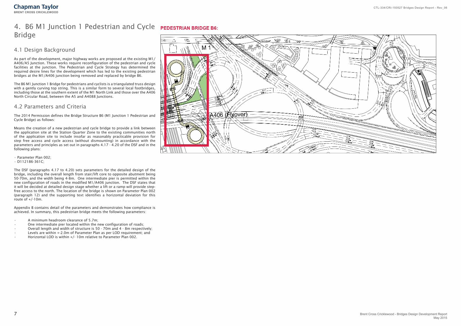
As part of the development, major highway works are proposed at the existing M1/A406/A5 Junction. These works require reconfiguration of the pedestrian and cycle facilities at the junction. The Pedestrian and Cycle Strategy has determined the required desire lines for the development which has led to the existing pedestrian bridges at the M1/A406 junction being removed and replaced by bridge B6.
The B6 M1 Junction 1 Bridge for pedestrians and cyclists is a triangulated truss design with a gently curving top string. This is a similar form to several local footbridges, including those at the southern extent of the M1 North Link and those over the A406 North Circular Road, between the A5 and A4088 Junctions.
4.2 Parameters and Criteria
The 2014 Permission defines the Bridge Structure B6 (M1 Junction 1 Pedestrian and Cycle Bridge) as follows:
Means the creation of a new pedestrian and cycle bridge to provide a link between the application site at the Station Quarter Zone to the existing communities north of the application site to include insofar as reasonably practicable provision for step free access and cycle access (without dismounting) in accordance with the parameters and principles as set out in paragraphs 4.17 - 4.20 of the DSF and in the following plans:
• Parameter Plan 002; • D112186-361C;
The DSF (paragraphs 4.17 to 4.20) sets parameters for the detailed design of the bridge, including the overall length from stair/lift core to opposite abutment being 50-70m, and the width being 4-8m. One intermediate pier is permitted within the new configuration of roads in the modified M1/A406 junction. The DSF states that it will be decided at detailed design stage whether a lift or a ramp will provide step-free access to the north. The location of the bridge is shown on Parameter Plan 002 (paragraph 12) and the supporting text identifies a horizontal deviation for this route of +/-10m.
Appendix B contains detail of the parameters and demonstrates how compliance is achieved. In summary, this pedestrian bridge meets the following parameters:
• A minimum headroom clearance of 5.7m;• One intermediate pier located within the new configuration of roads;• Overall length and width of structure is 50 - 70m and 4 - 8m respectively;• Levels are within +-2.0m of Parameter Plan as per LOD requirement; and• Horizontal LOD is within +/- 10m relative to Parameter Plan 002.
4. B6 M1 Junction 1 Pedestrian and Cycle Bridge
7
BRENT CROSS CRICKLEWOOD
Brent Cross Cricklewood - Bridges Design Development ReportMay 2015
CTL-334/CRI-150527 Bridges Design Report - Rev_06

4.3 Options Considered
In keeping with the normal expectation for a functional pedestrian and cycle bridge of the scale required, various steel truss solutions were considered. Concrete construction was precluded as it would require time consuming ‘wet’ working over a live carriageway and in the proximity of an electrified railway.
A prefabricated steel truss girder form of footbridge superstructure is considered the most suitable in addressing the key issues of buildability, minimal disruption and cost.
The prefabricated superstructure would be structurally complete with the majority of finishing and deck features installed prior to being lifted or transported into place. This mitigates the need to provide temporary works to support the main deck during installation, and eliminates the health and safety risk associated with carrying out major construction work at height. Furthermore, this type of construction allows the junction to be operational immediately after an overnight closure to install the main bridge spans.
The following prefabricated steel truss girder options were considered:
• 2-Span Continuous Warren Truss Girder Bridge;• 2-Span Continuous Vierendeel Truss Girder Bridge;• 2-Span Separated Warren Truss Girder Bridge;• Single Span Truss Girder Bridge;
4.4 Design
Following the options study a 2-Span Continuous Warren Truss Girder Bridge form was selected as the preferred solution. This form offers a compact solution; mitigates erection issues given the constricted nature of the site and provides a structure with a good appearance, whilst also complying with parameters and Pedestrian and Cycle Strategy requirements.
The design of Bridge B6 is intended to be a simple, functional and appropriate response to the requirements of its brief which is to provide a safe and accessible link over the North Circular Road. The preferred engineering solution as described above also relates to other existing bridges over the North Circular Road, for example the pedestrian bridge to the West of Staples Corner.
The finishes proposed are painted steel and aluminum, similar to other local bridges.
The General Arrangement drawings and Illustrative Plans for this bridge can be found in Appendix C.
4.5 Access
The Pedestrian and Cycle Strategy has reinforced the detail in Parameter Plan 002 that a shared pedestrian and cycle bridge should be provided across the M1/A406/A5 junction to form a key north/south link across the A406 with a clear width of at least 4.0m.
Ramped access is provided at both the north and south ends of the bridge in accordance with standards for pedestrians and cycles.
Inclusive Access
Bridge B6 will provide a new pedestrian and cycle bridge over the M1/A406 junction. The bridge will be accessed by stairs and by circular ramp. The bridge, stairs and ramps will be designed to accord with the geometrical requirements of DMRB standard BD 29/04 ‘Design Criteria for Footbridges’. The design includes:
• Cycle / pedestrian ramps have been designed with a gradient that is less -than the maximum 1 in 20 gradient.• The internal width of the ramp and bridge will be 4m.• Parapets will be set at 1.4m height.• Headroom provided on the ramps will be at least 2.7m.• The inner radius of the ramps will exceed 5.5m
8
BRENT CROSS CRICKLEWOOD
CTL-334/CRI-150527 Bridges Design Report - Rev_06
Brent Cross Cricklewood - Bridges Design Development ReportMay 2015
5. B7 Living Bridge
5.1 Design Background
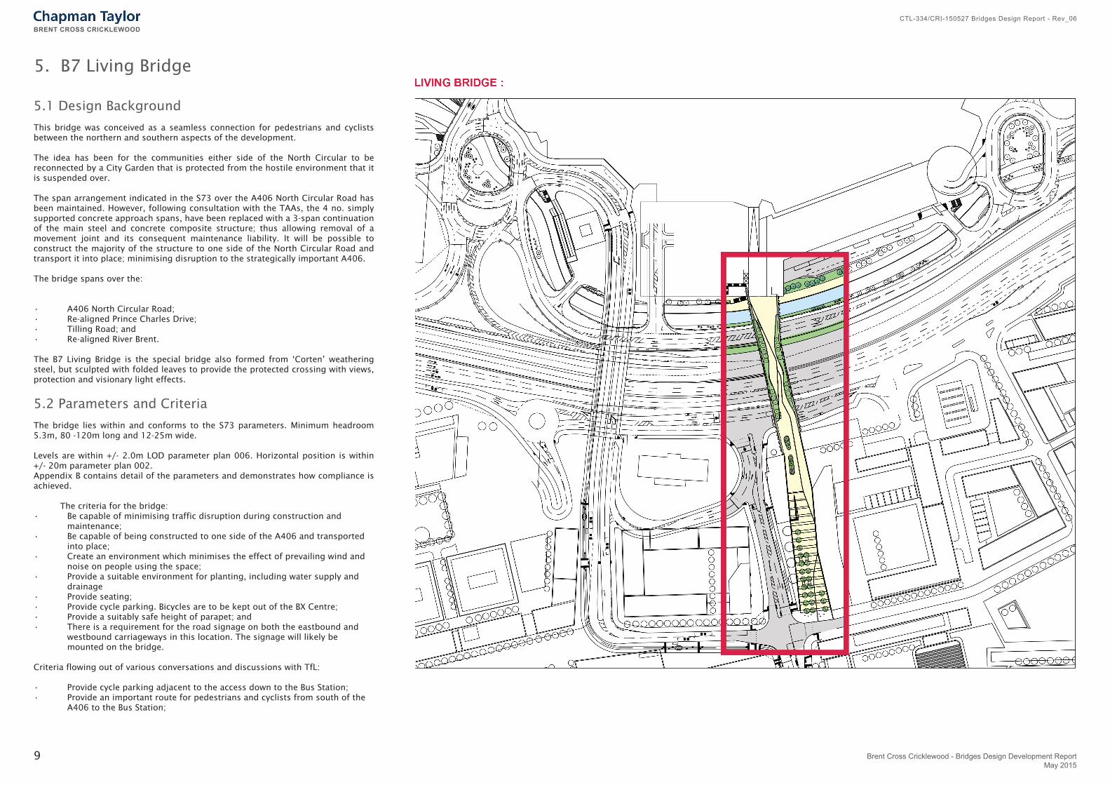
This bridge was conceived as a seamless connection for pedestrians and cyclists between the northern and southern aspects of the development.
The idea has been for the communities either side of the North Circular to be reconnected by a City Garden that is protected from the hostile environment that it is suspended over.
The span arrangement indicated in the S73 over the A406 North Circular Road has been maintained. However, following consultation with the TAAs, the 4 no. simply supported concrete approach spans, have been replaced with a 3-span continuation of the main steel and concrete composite structure; thus allowing removal of a movement joint and its consequent maintenance liability. It will be possible to construct the majority of the structure to one side of the North Circular Road and transport it into place; minimising disruption to the strategically important A406.
The bridge spans over the:
• A406 North Circular Road;• Re-aligned Prince Charles Drive;• Tilling Road; and• Re-aligned River Brent.
The B7 Living Bridge is the special bridge also formed from ‘Corten’ weathering steel, but sculpted with folded leaves to provide the protected crossing with views, protection and visionary light effects.
5.2 Parameters and Criteria
The bridge lies within and conforms to the S73 parameters. Minimum headroom 5.3m, 80 -120m long and 12-25m wide.
Levels are within +/- 2.0m LOD parameter plan 006. Horizontal position is within +/- 20m parameter plan 002. Appendix B contains detail of the parameters and demonstrates how compliance is achieved.
The criteria for the bridge:• Be capable of minimising traffic disruption during construction and maintenance; • Be capable of being constructed to one side of the A406 and transported into place;• Create an environment which minimises the effect of prevailing wind and noise on people using the space;• Provide a suitable environment for planting, including water supply and drainage• Provide seating; • Provide cycle parking. Bicycles are to be kept out of the BX Centre;• Provide a suitably safe height of parapet; and• There is a requirement for the road signage on both the eastbound and westbound carriageways in this location. The signage will likely be mounted on the bridge.
Criteria flowing out of various conversations and discussions with TfL:
• Provide cycle parking adjacent to the access down to the Bus Station;• Provide an important route for pedestrians and cyclists from south of the A406 to the Bus Station;
9
BRENT CROSS CRICKLEWOOD
Brent Cross Cricklewood - Bridges Design Development ReportMay 2015
CTL-334/CRI-150527 Bridges Design Report - Rev_06

• The design should provide legibility/views of the bus station whilst crossing the bridge so that people know where they are going; • The design, construction and maintenance should minimise lane closures and disruption to the A406;• TFL have advised that the cleaning/ maintenance of any fixed glazing would require lane closures.• The parapet should be sufficiently robust to be able to accommodate the loading from bridge strikes from an overheight vehicle, as per the requirements of design standards. This is because statistics show that bridge strikes can be expected, even for a bridge with over 5.3 m headroom. (This statistic has been confirmed by TfL.) A common cause of bridge strikes is from the unsecured Back Actor arm of a digger being transported on a HGV low loader. Therefore any elements of the structure (including the parapet) within 5.7m headroom above a vehicular carriageway will meet the Eurocode robustness requirements for vehicle impact. In accordance with normal practice local damage of the impacted elements will be permitted, as it is neither practicable nor safe to make structural members resistant to the substantial forces that may result from a vehicular impact. However, risk to users of the A406 below will be limited by selecting ductile materials for the parapet (e.g. steel) rather than brittle materials (e.g. glass) and the parapet will be designed so as not to become globally detached from the structure above, and thus will avoid a disproportionate consequence from a vehicle impact.
The overall arrangement of a composite steel and concrete deck remains unchanged since S73. However, an open steel plate ‘I’ beam has been chosen in preference to box beams as part of design development to improve maintenance and durability in agreement with the TAA.
The bridge is to carry fixed planters as noted on drawings in Appendix E.
Area loadings have assumed a central zone for pedestrians with planters on each side.
The Southern Approach is required to have vertical sides to maximise developable land either side.
Traffic signs on Living Bridge drawings are indicative only.Drainage and service ducts will be submitted at a later stage.
5.3 Options Considered
The flat deck and parapet solution supported the idea of passing over the North Circular A406 without being fully aware of it, creating the seamless connection. For the main bridge the following options were considered:
• Single span arch;• 3-span configuration for two flat deck options (box-girder and plate-girder options);• Hybrid structure; and• Cable stayed bridge.
In addition to the above, the TAA requested that a concrete deck option was also considered.
A number of options were also considered for the form of the Southern Approach as follows:
• Continuation of bridge spans;• Reinforced concrete deck on piled piers (i.e. continuation of bridge form);• Reinforced concrete deck spanning between lines of piles;• Reinforced earth ramp on stone columns;• Conventional fill embankment with sides supported by bored piles and soil mixing ground improvements; and• Reinforced earth ramp on ground improved by vertical drains and surcharging.
A number of options were considered for the parapets:
• Solid and circa 2.5 metres high to provide protection;• Low level parapets but this wouldn’t provide any protection from traffic noise and the prevailing wind;• Glazed parapets but they would require lane closures for cleaning, and disruption to traffic movement on North Circular Road;• A combination of solid and angled views to protect to the central area from noise and give views and interest to the northern and southern ends.
5.4 Design
It was concluded that a flat deck option was the favoured solution for this bridge from a Technical Approval perspective.
Of the two flat deck options, the option of a plate-girder solution was chosen because it is easier to fabricate, inspect and maintain. The girders are to be formed of ‘Corten’ weathering steel.
This form of construction meets the architectural requirement for an open, unimposing link between the Southern and Northern Development. A flare at the northern end allows for a natural pedestrian flow from Brent Cross Shopping Centre towards the bridge.
‘Corten’ weathering steel was chosen for the parapets for its natural earthy appearance.
The proposed ‘Corten’ weathering steel parapet will be restrained at the edge beam bottom flange level, in addition to its support at the concrete deck level. Plan bracing between the two outer beams will share the loads.
A risk assessment is being progressed to determine the level of vehicular containment required by a concrete up-stand and/or parapet during the Technical Approval process.
For the Southern Approach, the bridge form is to be extended over an area potentially to be used as a car park between plots 93 and 28 with a reinforced earth ramp on stone columns for the remainder of the approach.
The General Arrangement drawings and Illustrative Plans for this bridge can be found in Appendix E.
The design of the public realm space and the sculptural parapets is explained in the Design Report Appendix F.
Other technical criteria include provision for intermittent service maintenance vehicles.
10
BRENT CROSS CRICKLEWOOD
CTL-334/CRI-150527 Bridges Design Report - Rev_06
Brent Cross Cricklewood - Bridges Design Development ReportMay 2015

Inclusive Access
As level landings are not provided, a series of seating options will be provided along the routes to allow people who might find the gradient more challenging the opportunity to rest. Two of the seating areas on the Southern Approach are on flat islands set between the sloping routes, This follows precedents set within the Queen Elizabeth Park and conforms to the BXC Inclusive Access Strategy.
It is proposed that cyclists will have access to the bridge and cycle parking will be provided at both ends. However, it is the intention that the bridge is pedestrian prioritised and the design has been developed to this. The clear route has been widened to a minimum of 6m in response to the London Borough of Barnet’s comments to provide extra space for cyclists and pedestrians to share. Cycle access is not provided from the bridge into Brent Cross Shopping Centre and beyond; nor does it link to the London Cycle Network and as such will not attract commuter cycle traffic.
A combined public realm approach is proposed using a sequence of ‘spaces’ as opposed to a segregated cycle route. The landscape design aims to slow cyclists through the design of the path layout, planting and seating. The aim is to create a layout which encourages users to dwell in a city garden in the centre of the bridge. The graded approach route to the bridge is where cycle speeds are likely to be greater. For this section a more generous circulation space is provided, with a zone to the edge which cyclists are discouraged to use through seating and
5.5 Access
The Living Bridge provides access for pedestrians and cyclists between the north and south sides of the North Circular Road between the proposed Market Square and Brent Cross Main Square.
Travelling from the Market Square in the south, the approach to the bridge slopes upwards at circa 1 in 30 with handrails to either side . At intermediate points there are flat areas within the slope where wheelchair users and the less mobile may pause.
At the top of the slope there is seating and a number of cycle stands immediately before a multi-functional area. This space may host minor community events.
The location of the cycle stands relates to this area. In the central garden area the paved space is not less than 6m wide. Seating is concentrated within the concave spaces of the winding route to help maintain a clear 7m straight pathway for people moving through the space.
The bridge over the North Circular Road slopes at circa 1:220 from north to south, changing to circa 1:40 in area over Tilling Road.
There are 35 cycle stands distributed in 3 locations on the Southern Approach and bridge. At the northern end there are 19 cycle stands enabling the parking of 38 bicycles. There is no bicycle access into or through the Brent Cross Shopping Centre but there will be a bicycle channel on two staircases to the upper level walkway and to the lower riverside path.
In addition to this staircase, there will be two lifts and escalators connecting the Living Bridge down to the Bus Station and upper level walkway. Pedestrians entering Brent Cross Shopping Centre will walk down a sloping street to the Main Square. This street will be part of the Phase 1B North Reserved Matters and is likely to slope at between 1 in 25 and 1 in 30.
At the southern end of the approach, there will be anti-terrorism measures installed towards the southern end of the approach to prevent vehicle access in normal circumstances.
planting.
The landscaping strategy for Phase 1AN, including seating, was presented to CAF on the 13 October 2014. It was noted that further work is required on street-furniture proposals. This will be developed during detailed design and the seating along the Living Bridge will be developed in accordance with the BXC Inclusive Access Strategy.
To the north there is approximately a 9m change in level between Brent Cross Main Square, the Living Bridge and the proposed new Brent Cross Bus Station, which is on the level below. As detailed in the S73 application, a public lift for pedestrians and disabled people in wheelchairs will be provided to overcome this change in level.
11
For Illustrative Purposes Only
BRENT CROSS CRICKLEWOOD
Brent Cross Cricklewood - Bridges Design Development ReportMay 2015
CTL-334/CRI-150527 Bridges Design Report - Rev_06