
Bridge / Routers User And System Administration Guide · PDF fileAuto Learning the Frame Relay...
100
Perle 1700 Series Perle 1700 Series Perle 1700 Series Perle 1700 Series Bridge / Routers User And System Administration Guide Part number 5500071-14 © Copyright 2002 by Perle Systems Ltd.
Transcript of Bridge / Routers User And System Administration Guide · PDF fileAuto Learning the Frame Relay...

Perle 1700 SeriesPerle 1700 SeriesPerle 1700 SeriesPerle 1700 Series
Bridge / RoutersUser And System
Administration GuidePart number 5500071-14
© Copyright 2002 by Perle Systems Ltd.

Federal Communications Commission (FCC)
Note: This equipment has been tested and found to comply with the limits for a Class A digital device, pursuant to Part 15 of the FCC Rules. Theselimits are designed to provide reasonable protection against harmful interference when the equipment is operated in a commercial environment. Thisequipment generates, uses, and can radiate radio frequency energy and, if not installed and used in accordance with the instruction manual, may causeharmful interference to radio communications. Operation of this equipment in a residential area is likely to cause harmful interference in which casethe user will be required to correct the interference at his own expense.
Warning: The user is cautioned that modifications to this equipment can void the authority granted by the FCC to operate the equipment
The following repairs may be made by the customer: none.
Canadian Emissions Standard ICES-003
This digital apparatus does not exceed the Class A limits for radio noise emissions from digital apparatus as set out in the interference-causingequipment standard entitled “Digital Apparatus”, ICES-003 of the Industry Canada.
Cet appareil numérique respecte les limites de bruits radioélectriques applicables aux appareils numériques de Classe A prescrites dans la norme sur lematériel brouilleur: “Appareils Numériques”, NMB-003 édictée par Industrie Canada.
For products marked with the CE Telecommunications label, the following declarationapplies:
“The manufacturer declares that as shipped from the factory this product is in compliance with the CE Telecommunications Terminal Equipment
Directive 91/263/EEC with the marking applied in respect of this declaration, and in respect of the following telecommunicationsinterfaces,
X.21(V.11) - NET 1X.21bis(V.28) and X.21bis(V.35) - NET 2PSTN ISDN Basic Rate Interface compatible with I.420 - NET 3
The manufacturer further declares that the product conforms with the requirements of the Low Voltage Directive 73/23/EEC and with therequirements of the EMC Directive 89/336/EEC (for radiated emissions at the Class A level). This product is not intended for residentialapplications.”
ISDN Type Approval Labels
Labels for National ISDN Type Approvals can be found on the inside surface of the backpanel of the ISDN module.
Canadian ISDN Approval
The ISDN interface of this device is intended for direct connection to the S/T jack of an NT-1 unit and therefore does not require CommunicationsCanada certification. The P1730 & PRO should only be connected to Communications Canada approved NT-1 units.
Statements for ISDN U Module
NOTICE: The Canadian Department of Communications label identifies certified equipment. This certification means that the equipment meetscertain telecommunications network protective, operational and safety requirements. The Department does not guarantee the equipmentwill operate to the user’s satisfaction.
Before installing this equipment, users should ensure that it is permissible to be connected to the facilities of the local telecommunicationcompany. The equipment must also be installed using an acceptable method of connection. The customer should be aware thatcompliance with the above conditions may not prevent degradation of service in some situations.
Repairs to certified equipment should be made by an authorized Canadian maintenance facility designated by the supplier. Any repairs oralteration made by the user to this equipment, or equipment malfunctions, may give the telecommunications company cause to request theuser to disconnect the equipment.
Users should ensure for their own protection that the electrical ground connections of the power utility, telephone lines and internalmetallic water pipe system, if present, are connected together. This precaution may be particularly important in rural areas.
CAUTION: Users should not attempt to make such connections themselves, but should contact the appropriate electric inspection authority, orelectrician, as appropriate.
Using This Manual
This Installation and Applications Guide provides the basic information required to initially set-up and configure theP1730 & PRO Bridge/Router. This guide is organized into the following sections:
“Installation” provides instructions for installing the P1730 & P1705.
“Typical Applications & How to Configure Them” provides simple configuration examples for typicalapplications in which the P1705 & P1730 might be used. The applications described in this document are forexample only and provide a method of quick configuration of the P1705 & P1730. The applications andcorresponding configuration may be combined if the operation of the P1705 & P1730 requires more complexity. Formore complete information on all of the configuration parameters available please refer to the appropriate MenuReference Manual file for your operating software on the accompanying CD-ROM.
“Introduction to Filtering” provides an introduction to the pattern filtering options of the P1705 & P1730.Several examples of typical pattern filters are also provided.
”Menu Trees” provides a graphical tree type overview of the structure of the built-in menu system of the P1705 &P1730. All of the configuration is performed using the options provided in the menu system. The Menu Tree is likean index to the menu options.
“Octet Locations on Ethernet Frames” provides a graphical representation of the various common Ethernetframes that the P1705 & P1730 will bridge or route. When defining a pattern filter, these frame displays indicate theoffset values to use in order to define the pattern filter correctly.
“Servicing Information” provides information on changing Link interfaces.
“Interface Pinouts” provides information on Link interface connectors.
Using The Electronic Reference Manuals
This manual and the P1705 & P1730 Reference Manuals are provided as Adobe Acrobat PDF files on theaccompanying CD-ROM.
The Adobe Acrobat Reader program required to view the Manuals is also loaded onto the CD-ROM. In addition, it isavailable for most computer operating platforms from Adobe on the Internet at: www.adobe.com.
The Reference Manual provides the following information:Introduction to bridging, routing, and P1705 & P1730 features,Pin out references for the link modules,List of event and alarm logs, andExpanded description of programmable filtering.
The PPP Menu Reference Manual provides the following information:Complete description of the options for the built-in menu system, including PPP ISDN, PPP Leased Line,1490 Frame Relay and encapsulated PPP Frame Relay.

Contents
1 INSTALLATION 1
Unpack the Router................................................................................................. 1Select a Site ............................................................................................................. 1Identify the Reset Switch ...................................................................................... 2Identify the Connectors ........................................................................................ 3
P1705................................................................................................................................ 3P1730................................................................................................................................ 3Connect to the Console................................................................................................. 4Make the Link Connection(s)....................................................................................... 4
Power Up the Bridge/Router............................................................................... 5Managing the P1705 & P1730 Using the Menus ............................................. 5Conventions............................................................................................................ 6Login to Bridge/Router and Enter the Required Configuration.................... 7
Setting the T1/E1Parameters (T1/E1 WAN only) .................................................. 8Mandatory Configuration.............................................................................................. 10
Identify the Status LEDs ...................................................................................... 11
2 TYPICAL APPLICATIONS & HOW TO CONFIGURE THEM 12
Bridging and Routing ............................................................................................ 13Should You Bridge or Route? .............................................................................. 13
Bridging............................................................................................................................ 14IP Routing ....................................................................................................................... 15
IP Addressing............................................................................................................................16Masks ..........................................................................................................................................17IP Subnets..................................................................................................................................17IP Default Gateway..................................................................................................................19IP Static Route ..........................................................................................................................19
IPX Routing .................................................................................................................... 20Novell Servers in Both Locations..........................................................................................20Novell Servers in One Location Only ..................................................................................21Novell Server with Dual LANs..............................................................................................23
PPP Overview................................................................................................................. 24PPP Link Configuration..........................................................................................................24Numbered Links.......................................................................................................................24Unnumbered Links ..................................................................................................................25Multilink Operation..................................................................................................................26
Basic WAN Configurations.................................................................................. 27Basic ISDN Connections.............................................................................................. 27
PPP ISDN Manual Call Quick Connections.......................................................................30IPX Router Manual Call Connection ..............................................................................31IP Router Manual Call Connection .................................................................................31
Basic Frame Relay Configuration ................................................................................ 32Auto Learning the Frame Relay Configuration...................................................................33Manual Configuration - LMI Type........................................................................................34Quick Start Frame Relay .........................................................................................................35
Basic Leased Line Configuration ................................................................................. 36Quick Start PPP Leased Line Connections .........................................................................36
Bridge Connection..............................................................................................................37IP Router Connection........................................................................................................37IPX Router Connection.....................................................................................................37
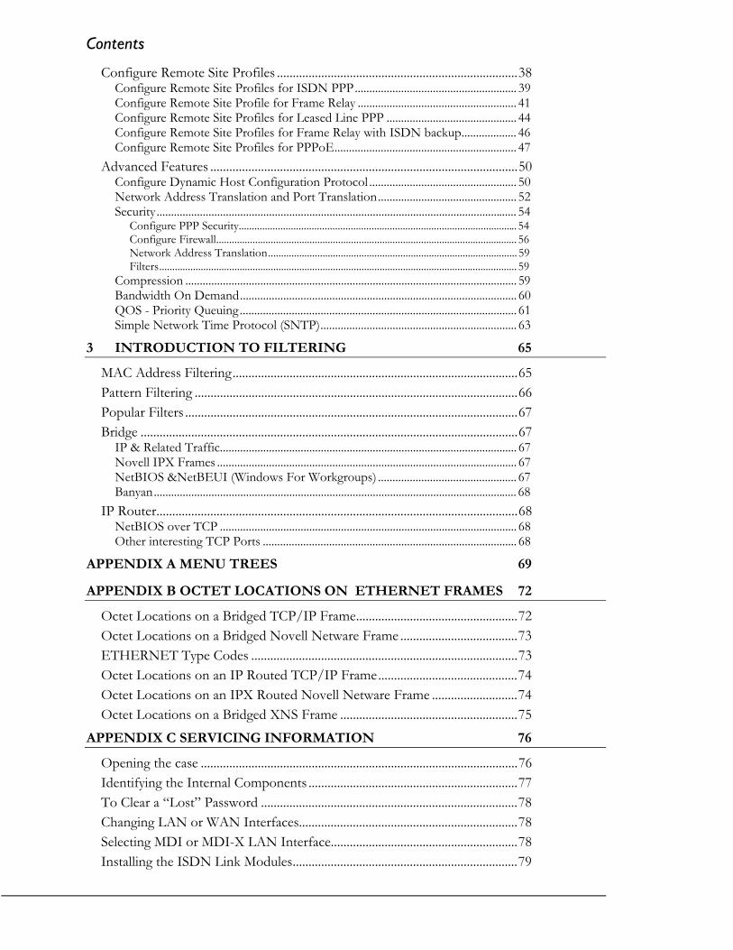
Contents
Configure Remote Site Profiles ............................................................................38Configure Remote Site Profiles for ISDN PPP........................................................ 39Configure Remote Site Profile for Frame Relay ....................................................... 41Configure Remote Site Profiles for Leased Line PPP ............................................. 44Configure Remote Site Profiles for Frame Relay with ISDN backup................... 46Configure Remote Site Profiles for PPPoE............................................................... 47
Advanced Features .................................................................................................50Configure Dynamic Host Configuration Protocol ................................................... 50Network Address Translation and Port Translation................................................ 52Security............................................................................................................................. 54
Configure PPP Security........................................................................................................... 54Configure Firewall.................................................................................................................... 56Network Address Translation................................................................................................ 59Filters.......................................................................................................................................... 59
Compression ................................................................................................................... 59Bandwidth On Demand................................................................................................ 60QOS - Priority Queuing................................................................................................ 61Simple Network Time Protocol (SNTP).................................................................... 63
3 INTRODUCTION TO FILTERING 65
MAC Address Filtering..........................................................................................65Pattern Filtering ......................................................................................................66Popular Filters .........................................................................................................67Bridge .......................................................................................................................67
IP & Related Traffic....................................................................................................... 67Novell IPX Frames ........................................................................................................ 67NetBIOS &NetBEUI (Windows For Workgroups) ................................................ 67Banyan.............................................................................................................................. 68
IP Router..................................................................................................................68NetBIOS over TCP ....................................................................................................... 68Other interesting TCP Ports ........................................................................................ 68
APPENDIX A MENU TREES 69
APPENDIX B OCTET LOCATIONS ON ETHERNET FRAMES 72
Octet Locations on a Bridged TCP/IP Frame...................................................72Octet Locations on a Bridged Novell Netware Frame .....................................73ETHERNET Type Codes ....................................................................................73Octet Locations on an IP Routed TCP/IP Frame............................................74Octet Locations on an IPX Routed Novell Netware Frame ...........................74Octet Locations on a Bridged XNS Frame ........................................................75
APPENDIX C SERVICING INFORMATION 76
Opening the case ....................................................................................................76Identifying the Internal Components ..................................................................77To Clear a “Lost” Password .................................................................................78Changing LAN or WAN Interfaces.....................................................................78Selecting MDI or MDI-X LAN Interface...........................................................78Installing the ISDN Link Modules.......................................................................79

Contents
Processor settings for the ISDN Link Modules ................................................ 79Changing the Termination Straps on the ISDN S/T Interface ...................... 80Connecting to the ISDN-U Link Module .......................................................... 80Performing a Software Upgrade .......................................................................... 81
APPENDIX D INTERFACE PINOUTS 2.83Pinout Information ........................................................................................................ 2.83Link Clocking Information........................................................................................... 2.83ATL-CSU/DSU Link Module Information .............................................................. 2.83Console Pinouts.............................................................................................................. 2.3
V.24 & RS232C Link Pinouts .............................................................................. 2.4V.11/X.21 Link Pinouts ...................................................................................... 2.5RS442 & RS530 Link Pinouts .............................................................................. 2.6V.35 Link Pinouts .................................................................................................. 2.7RS232 Null-Modem Cable Configuration.......................................................... 2.8V.35 Null-Modem Cable Configuration............................................................. 2.9RS530 Null-Modem Cable Configuration.......................................................... 2.10RS530 To RS449 Conversion Cable ................................................................... 2.11V.11/X.21 Null-Modem Cable Configuration .................................................. 2.12
1
1 Installation
The P1705 & P1730 are flexible Ethernet Bridge/Routers that may be configured to serviceLocal Area Networks and Wide Area Network connections over leased lines, ISDN circuits,and frame relay permanent virtual circuits. The P1705 supports a single LAN and one ortwo WAN links (one ISDN BRI interface or two other WAN modules). The P1730supports two independent LANs plus one WAN interface or a single LAN plus two WANinterface modules (if two ISDN BRI modules are installed, this will provide 4 WAN links)
PPP ISDN units provide bridging, IP/IPX routing, and compression over a PPP ISDNconnection and support an ISDN BRI interface via an integral ISDN-ST or ISDN-U linkmodule. The ISDN BRI interface supports two 64 Kbps B-channels.
PPP Lease line units provide bridging, IP/IPX routing, and compression and support oneor two physical wide area network (WAN) links that may operate at speeds up to 2.048Mbps.
Frame Relay units provide bridging and IP/IPX routing and support 1 to 128 PermanentVirtual Circuit (PVC) across two physical wide area links running RAW 1490 orencapsulated PPP.
The following instructions provide a quick set-up guide for installation of the P1705 &P1730 Ethernet Bridge/Routers:
Unpack the Router
Rough handling during shipment can damage electronic equipment. As you unpack thebridge/router, carefully check for signs of damage. If damage is suspected, contact theshipper. Save the box and all packing material to protect the bridge/router should it everneed to be moved or returned for service.
Check the packing slip that identifies the components and the LAN connector.
Select a Site
Place the bridge/router in a well ventilated area. The site should maintain normal officetemperature and humidity levels. Air vents located on the sides of the bridge/router musthave approximately one inch / 2.5 centimeters of clearance from any object.

Applications
2
Identify the Reset Switch
The small hole under the front right corner of the faceplate is used in case a hardware resetis required. The end of a paper clip is sufficient to toggle the small switch behind the hole.
FrontView
BottomView
RESET
Figure 1-1 Location of the Reset Hole on Router

Applications
3
Identify the Connectors
P1705The P1705 may be ordered with a 10Base2, 10Base5, or 10BaseT LAN interface.
If this P1705 has an ISDN U or S/T Module, it must only be installed in the slot 1(leftmost position when viewed from the rear of the unit). The slot 2 position may beunused and covered with a blank panel or may contain another type of module. If a secondWAN module is installed, only one BRI channel will be available for use.
Figure 1-2 Rear View of the P1705 with ISDN interface
P1730The P1730 is configured with a 10/100BaseT LAN and either one or two optional interfacemodules. The optional modules may be a second LAN (10 BaseT), a second LAN plus oneWAN module, a single WAN module or two WAN modules.
Important: If a second LAN module is installed, it must be in the slot 1 (leftmost positionwhen viewed from the rear of the unit) to operate. In addition, if only oneoptional interface module is installed, it must be in slot 1
Each interface may be changed by simply removing the existing module and installing a newmodule. Refer to Appendix D: Servicing Information for information on replacing modules.
CONSOLERS-232/V.24
Link 1 module Link 2 module LAN/Console module
Power connector
CSU/DSULINE
10/100 BT LAN
MDI-X MDI
Figure 1 -3 Rear View of the P1730 with a single LAN connection and two WANmodules

Applications
4
CONSOLE
10/100 BT LAN
MDI-X MDI
LAN/Console module
Power connector
RS-232/V.24
LAN 2 module Link 2 module
10 BT LAN
MDI-X MDI
Figure 1-4 Rear View of the P1730 with Dual LAN connections and a single WANmodule
Connect to the ConsoleConnection to the bridge/router operator’s console is made through the DB25 connectorlabeled CONSOLE on the back of the bridge/router.
Connect the console port of the Router to a computer running an asynchronouscommunication package or a standard asynchronous terminal. The bridge/router supportsautobaud rates at 1200, 2400, 9600, 19,200, 38,400 or 57,600 bps. Both the bridge/routerand the bridged network are configured through the use of “hotkey” Menus.
Make the Link Connection(s)By default the links are configured as permanent DTE interfaces. The clocking for each linkwill be provided by the DCE device connected to each link.
The V.35 link modules require interface converters that convert from a DB25 connector toa male 34-pin (V.35) connector used for the V.35 interface. Be sure to secure the cableconnector(s) to the bridge/router and the communications equipment with the connectorscrews to prevent accidental disconnection.
The CSU/DSU module uses a RJ-48S connector to interface with the digital data service.
G.703 modules use a standard BNC connector with a 75 ohm cable.
The ISDN-ST interface module of the ISDN Router provides a RJ-45 connector to connectto the RJ-45 connector of the NT1 provided with your ISDN service.
The ISDN-U interface module of the ISDN Router provides an integrated NT1 with a RJ-45 connector to connect directly with your ISDN service.
Pinouts for the WAN connectors are listed in Appendix D of this manual.

Applications
5
Power Up the Bridge/Router
Once the LAN and Link connections are made and the console is connected to a terminal,you are ready to power-up the router. Connect the AC power cord to the back of the routerand plug the cord into the AC wall outlet.
Observe the LEDs as the bridge/router powers up. The LEDs will go through a circularflashing pattern as the power-up diagnostics are performed. After the power-up diagnosticsare finished, the Power LED will go from red to green.
Enter at least one <RETURN> (up to three if necessary) in order for the bridge/router todetermine the baud rate of the terminal used for the console (i.e., autobaud). The followinginformation will now be seen on the console connected to the bridge/router :
Terminals supported:ansi, avt, ibm3101, qvt109, qvt102, qvt119, tvi925,tvi950, vt52, vt100, wyse-50, wyse-vp, teletypeEnter terminal type:
Select the terminal type being used if listed and enter its name (in lower case) at the prompt,or choose the terminal type teletype if your terminal is not listed. This terminal typeoperates in scroll mode and may be used successfully until a custom terminal definition iscreated.
Managing the P1705 & P1730Using the Menus
This section describes the minimum configuration parameters required when setting up theP1705 & P1730. Each of the configuration scenarios requires setting of operationalparameters on the P1705 & P1730. The built-in menu system of the P1705 & P1730 is usedto configure the unit.
The router menu system operates on a “hotkey” principle; navigating around the menusystem is done by typing the number associated with the desired option; the P1705 & P1730acts on the choice immediately (no need to hit the “enter” key).
The menu system consists of different menu levels each containing new configuration options.Navigation back out of a nested menu is easily accomplished by pressing the tab key. The tabkey takes you to the previous menu level. If you wish to move from your current menulocation directly to the main menu simply press the equals “=” key.
When choosing menu options that will toggle between values, simply pressing the numberassociated with that option will cause the options value to change. Each successive selectionof the option will cause the option’s value to change again.
Some menu options require input from the operator. When selecting an option thatrequires a value, the menu system will display the range of values acceptable and a promptsymbol “>”. Enter the new value at the prompt symbol and press enter. Should you makean error in entering the new value, the <BACKSPACE> key (for most terminals) deletes themost recently entered characters.

Applications
6
Conventions
Throughout this section, P1705 & P1730 menu options are shown that are required for thevarious configuration choices. The appropriate menu options are shown in each instance inthe following format:
Configuration Option Name
Location: Main
Sub-Menu Name Sub-Menu Name
Option Name
The configuration option is shown as well as the options location withinthe menu system. The character indicates that a sub-menu levelmust be chosen. The option name is finally shown in italics.
The keyboard graphic in the left margin indicates that this is informationthat the user will have to enter for configuration.
The note icon is used to provide miscellaneous information on the configuration andset-up of the router.
Configuration: The Configuration Note is used to indicate that there may be a difference inNote configuration between the various operational modes of the router. This may mean for example that the remote site set-up is configured differently for an ISDN PPP router than for Frame Relay.
The information icon is used to indicate that more information is available on thissubject. The information is usually located within another document as specified.
The caution icon indicates that caution should be taken when performing this task.

Applications
7
Login to Bridge/Router and Enter the RequiredConfiguration
At the login screen type a 1 and the default password to enter the menu system of theRouter. The default password is “BRIDGE” (case sensitive) and should be changed ifsecurity is desired.
With the options of the built-in menu system, the router may be configured to operatewithin your environment.
Refer to the PPP Menus Manual file for your operating software on the accompanying CD-ROM for a complete description of all the Menu Options.
The menu system of the router may also be used to view system statistics.
Note: Bridge/Router database changes and statistics viewing may be done remotely by establishing Telnetconnections to a partner bridge/router across the WAN. This is accomplished by selecting the “Telnet”option.
Location: Main
Configuration Access Set-up
Telnet Set-up Telnet
Specify the name or IP address of the router you wish to connect to forconfiguration purposes or viewing of statistics.
Noting the Device name at the top left of each Menu may identify therouter being controlled.
If there is no data transmitted or received for a period of 5 minutes, theTelnet session will be disconnected.
To disconnect from the router being controlled, enter Control-C ( ^C ).
Telnet security considerations: Telnet may be disabled to prevent remote accesscontrol of the router. If Telenet access is enabled, the device password should bechanged to some value other than the default to prevent unauthorized access.
Location: Main
Configuration Access Set-up
Device Set-up Password
Applications
8
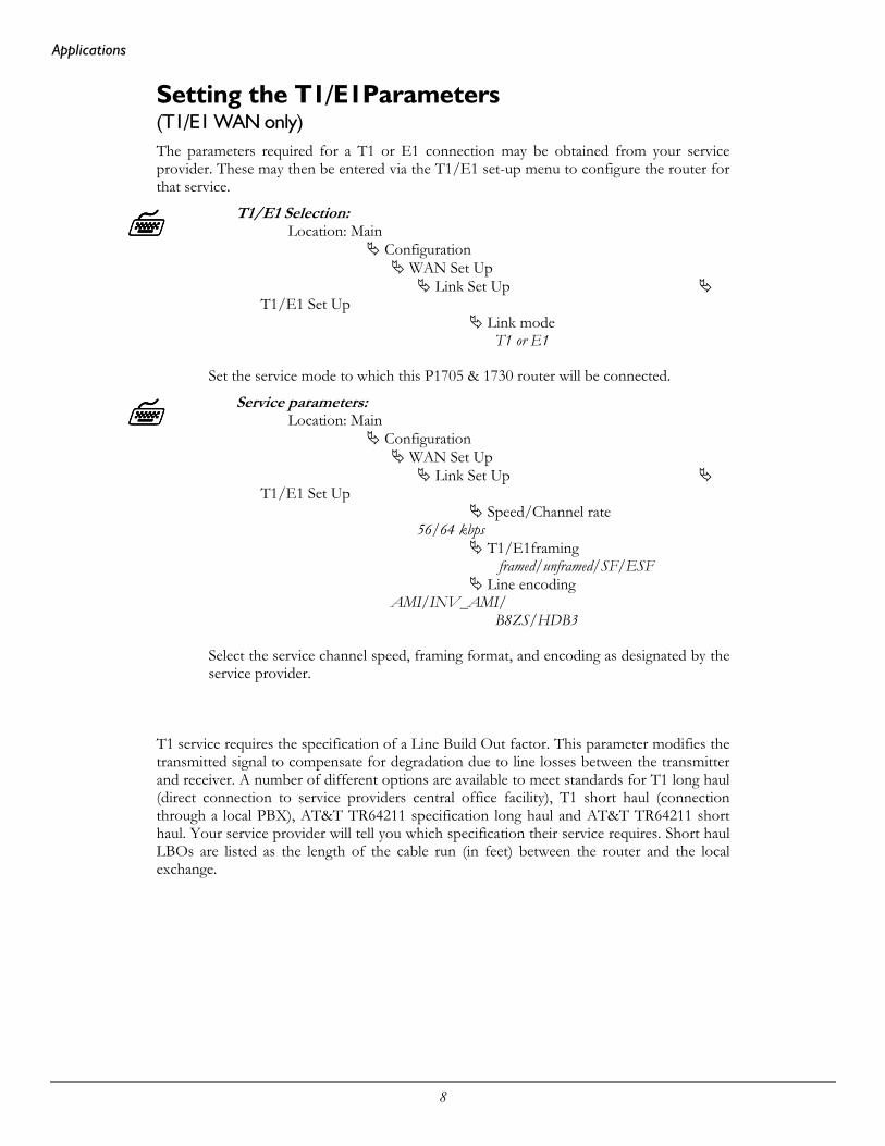
Setting the T1/E1Parameters (T1/E1 WAN only)The parameters required for a T1 or E1 connection may be obtained from your serviceprovider. These may then be entered via the T1/E1 set-up menu to configure the router forthat service.
T1/E1 Selection:Location: Main
Configuration WAN Set Up
Link Set UpT1/E1 Set Up
Link modeT1 or E1
Set the service mode to which this P1705 & 1730 router will be connected.
Service parameters:Location: Main
Configuration WAN Set Up
Link Set UpT1/E1 Set Up
Speed/Channel rate56/64 kbps
T1/E1framing framed/unframed/SF/ESF
Line encodingAMI/INV_AMI/
B8ZS/HDB3
Select the service channel speed, framing format, and encoding as designated by theservice provider.
T1 service requires the specification of a Line Build Out factor. This parameter modifies thetransmitted signal to compensate for degradation due to line losses between the transmitterand receiver. A number of different options are available to meet standards for T1 long haul(direct connection to service providers central office facility), T1 short haul (connectionthrough a local PBX), AT&T TR64211 specification long haul and AT&T TR64211 shorthaul. Your service provider will tell you which specification their service requires. Short haulLBOs are listed as the length of the cable run (in feet) between the router and the localexchange.

Applications
9
E1 service does not require line build out selection.
Set Link Interface Type:Location: Main
Configuration WAN Set Up
Link Set UpT1/E1 Set Up
LBOas specifed
T1 long-haul LBOs: L0db, L7.5db, L15db, L22.5db
Short haul LBOs: S0to110ft, S110to220ft, S220to330ft, S330to440ft,S440to550ft, S550to660ft
AT&T standard TR64211long-haul connection: TL0db
AT&T standard TR64211 short-haul connection: TS0to110ft, TS110to220ft,TS220to330ft, TS330to440ft, TS440to550ft, TS550to660ft
If fractional T1/E1 service is being provided, you will need to specify thechannels/timeslots to be used.
Set Link Interface Type:Location: Main
Configuration WAN Set Up
Link Set UpT1/E1 Set Up
Slot/Channel Set Up Startfirst channel Numbernumber of channels
Some E1 service providers reserve timeslot 16 for network management use. If your servicespecifies that timeslot 16 is for their use, toggle this option to reserved
Set Link Interface Type:Location: Main
Configuration WAN Set Up
Link Set UpT1/E1 Set Up
Slot/Channel Set Up E1 Timeslot 16reserved

Applications
10
Mandatory ConfigurationThe P1705 & P1730 requires a minimum amount of mandatory configuration in order tooperate. The following table identifies the configuration parameters that must be definedfor proper operation under the operational states shown in the table.
Bridge IP Router IPX Router
none IP Address none
ISDN - U ISDN – S/T PPP ISDN
ISDN Switch Type ISDN Switch Type B channel assignmentDirectory Numbers Directory Numbers Remote Site Profile
Frame Relay Lease Line PPP Lease Line
none (North America) none none (International)Remote Site Profile
Frame Relay enabled(International only)
Frame Relay disabled(North America only)
The configuration options required for proper initial operation are described in Section 2:Typical Applications and How to Configure Them. Each configuration requires a differentset of parameters to be entered.
Refer to Section 2 for details on configuring the P1705 & P1730 in different operationalstates. Also refer to the P1705 & P1730 Menus Manual file for your operating software onthe accompanying CD-ROM for a complete description of all the Menu Options.
Other options may be changed depending upon specific installation configurations. Refer tothe menu tree in Appendix A for a reference of the menu structure and options.
Applications
11
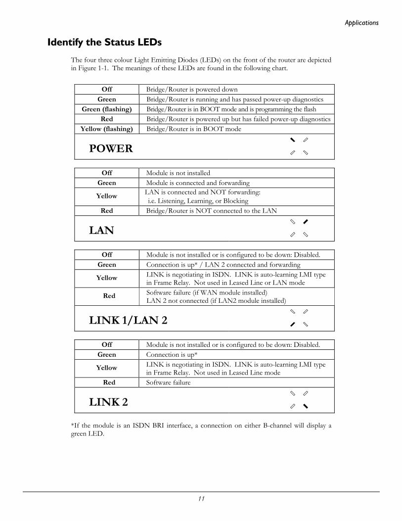
Identify the Status LEDs
The four three colour Light Emitting Diodes (LEDs) on the front of the router are depictedin Figure 1-1. The meanings of these LEDs are found in the following chart.
Off Bridge/Router is powered downGreen Bridge/Router is running and has passed power-up diagnostics
Green (flashing) Bridge/Router is in BOOT mode and is programming the flashRed Bridge/Router is powered up but has failed power-up diagnostics
Yellow (flashing) Bridge/Router is in BOOT mode
POWER
Off Module is not installedGreen Module is connected and forwarding
Yellow LAN is connected and NOT forwarding: i.e. Listening, Learning, or Blocking
Red Bridge/Router is NOT connected to the LAN
LAN
Off Module is not installed or is configured to be down: Disabled.Green Connection is up* / LAN 2 connected and forwarding
Yellow LINK is negotiating in ISDN. LINK is auto-learning LMI typein Frame Relay. Not used in Leased Line or LAN mode
Red Software failure (if WAN module installed)LAN 2 not connected (if LAN2 module installed)
LINK 1/LAN 2
Off Module is not installed or is configured to be down: Disabled.Green Connection is up*
Yellow LINK is negotiating in ISDN. LINK is auto-learning LMI typein Frame Relay. Not used in Leased Line mode
Red Software failure
LINK 2
*If the module is an ISDN BRI interface, a connection on either B-channel will display agreen LED.

12
2 Typical Applications & How to Configure Them
The P1705 & P1730 are flexible Ethernet Bridge/Routers. This section will describe how toset-up the P1705 & P1730 routers using each of its networking functions. Note thatdepending on the model of unit and what interface modules are installed, some of theconfiguration examples may not apply; for example, if no ISDN BRI module is installed, thesections on setting up an ISDN PPP router would not apply.
The P1705 & P1730 routers may be configured as a simple Ethernet bridge, an Ethernet IProuter, an Ethernet IPX router, or a combination of the three. When operating the router asa combination bridge/router, simply configure each of the components separately.
Note: The configuration options described within this section are only for initial set-up andconfiguration purposes. For more complete information on all of the configurationparameters available please refer to the P1705 & P1730 Menus Manual file on theaccompanying CD-ROM.
Important: The P1705 & P1730 uses FLASH memory to store the configurationinformation. Configuration settings are stored to FLASH memory after therehas been 30 seconds of idle time. Idle time is when there is no selection ormodification of the value in the built-in menu system. If you wish to save aconfiguration immediately, enter “=” to get to the main menu, then selectoption 5 “Save configuration”.

Applications
13
Bridging and Routing
Should You Bridge or Route?
When connecting two networks together, the first question to ask is “should I bridge orroute”? The decision to bridge or to route may be decided by how the existing networkshave been already set-up.
Bridging should be used when the network consists of non-routable protocols or routableprotocols using the same network numbers. Some protocols can only be bridged; some ofthe more well known are NetBEUI (used by Microsoft Windows), and LAT (used by DigitalEquipment Corp.).
If your IPX or IP network address is the same at both locations, bridging is simpler andrequires less configuration. If the locations are to be routed together, the network numberswill have to be different in both cases; this could require extensive reconfiguration.
IPX routing should be used if the two locations are already set-up with different IPXnetwork numbers. Routing IPX will minimize the number of SAP and RIP messages beingsent across the WAN.
IP routing should be used if the two locations are already set-up with different IP networknumbers or if you wish to divide your one IP network number into two sub-networks.
In some cases both bridging and routing may be required. Routing may be required for IPinformation and bridging may be required for NetBEUI.

Applications
14
BridgingAn Ethernet bridge intelligently forwards Ethernet data packet traffic between connectednetworks. The traffic may be across the Wide Area Network (illustrated below) or, in thecase of the P1730, may be between two LANs connected to the same P1730.
Figure 2 -1 Networks Bridged across a WAN link
Ethernet bridges simply forward information based on Ethernet MAC addresses. If apacket is destined for a device located on a different network than the device that sent thepacket, the bridge will forward that packet to the connected network. If a packet is destinedfor a device located on the same local network as the originating device, the bridge willignore the packet.
Ethernet bridges also communicate to each other using what is called the Spanning TreeProtocol (STP). STP is used to prevent loops in a network which cause traffic to be re-broadcast again and again causing network congestion.
The P1705 & P1730 are pre-configured to operate as an Ethernet bridge compatible withthe IEEE 802.1d Spanning Tree Protocol definitions. This means that withoutconfiguration modifications, the P1705 & P1730 will bridge Ethernet traffic to its partnerbridges when the Wide Area Network (WAN) connection has been established.
The P1705 & P1730 are also pre-configured as an IPX router. This means that ifyou wish to bridge IPX traffic instead of routing it, you must disable the IPX routingfunction of the router. Once IPX routing has been disabled, all IPX traffic will bebridged between networks.
To set-up a bridge between two LANs using a dual LAN P1730, all that is required is thatthe LANs be connected to the router.
To set-up a bridge between two networks connected by a WAN link:
− Connect each router to the LAN(s) it will be serving− Connect the WAN interface of each router to the equipment supplied by the service provider− Configure the remote site profile of the partner router if necessary− Establish the WAN connection
WAN connection
Windows for Workgroups Computers Windows for Workgroups Computers
Network #1 Network #2

Applications
15
IP RoutingAn Ethernet IP router is used to intelligently route Internet Protocol (IP) traffic to anothernetwork. The networks may be connected across a WAN link (illustrated below) or twoLANs connected to the same dual LAN P1730.
Figure 2 -2 IP Networks Routed across a WAN link
IP routers forward IP frames based upon their IP destination address and an internalrouting table. The router maintains the internal routing table with the connected network IPaddresses and, for WAN link connections, the remote partner IP routers associated withthose networks. When an IP frame is received, the destination IP address is examined andlooked up in the routing table. In the case of a dual LAN router, if the destination IPaddress is on the other LAN, the packet is routed there. For WAN connections, if thedestination IP network is found in the routing tables, the IP router sends the IP frame to theremote partner router that is connected to the appropriate remote IP network. If no explicitroute entry is found in the routing table, the IP frame is sent to the Default Gateway. TheDefault Gateway may be learned from the LAN or may be set manually (see section 2.1.2.3).
To configure an router for IP routing between networks, the following parameters must bedefined in the built-in menu system.
1. IP Address
Location: Main
Configuration LAN Set-up
LAN IP Set-up IP Address / Size of Subnet Mask
If this P1730 has the dual LAN option installed, you will first be asked which LAN toreference (1 or 2). Both LANs must have unique IP addresses to use IP routing.
WAN connection
TCP/IP Network TCP/IP Network
Network #1
IP Network Address199.169.1.0
IP Network Address199.169.2.0
Router IP Address 199.169.2.12
Router IP Address 199.169.1.10
Network #2

Applications
16
IP Addressing
Devices on an IP network are located by their IP addresses, which is a 32 bit numberdivided into four 8 bit fields. The IP address identifies both the network and the host device(also known as a node) on that network. The address is usually written as the four decimalvalues for the fields (between 0 and 255) separated by decimal points; for example196.65.43.21.
The high order field defines the IP class of the address. There are three commonly usedclasses of standard IP addresses:
A: 1 to 127
B: 128 to 191
C: 192 to 223
For Class A addresses, only the first 7 bits of the high order field represents the networkaddress, so there can be 127 networks. The remaining three fields are the host portion of theaddress – there can be over 16 million (224) host devices on each class A network.
Class B uses the first two fields for network addresses and can address approximately 16,000networks. The two low order fields allow approximately 65,000 host addresses (216) for eachnetwork.
Class C uses three high order fields to address over 2 million networks; the low order field isused to address up to 253 hosts (the addresses with all bits set to 1 and all 0 are reserved fornetwork use; so addresses available from 8 bits = 255 minus the 2 reserved).
IP addresses within a private network may be assigned arbitrarily, however, if that network isto interconnect with the global Internet, it is necessary to obtain a registered IP address.
For example, a small company is connected to the Internet; they are assigned a single class CIP network address (199.169.100.0). This network address allows the company to define upto 253 host addresses within their network.

Applications
17
Masks
The portion of the IP address to use as the network address is specified by using a mask; amask is the contiguous number of bits to be used for the network address all set to 1. Whenthe mask is logically ANDed with an IP address, the result is the network address. The maskis specified by entering the mask size as the number of bits in the mask. For the standardClass A, B and C Internet addresses, the mask sizes would be 8, 16 and 24 respectively.
Networks are not restricted to the above standard sizes; the mask (and hence the networkaddress it specifies) may be any number of bits from 8 to 32. This gives much moreflexibility to match the size of the two fields of the IP address to the number of networksand hosts to be serviced.
IP Subnets
An IP network may be divided into smaller networks by a process called sub-netting. Asubnet is specified using some of the high order bits of the host field of the IP address forsub-network addressing. The portion of the IP address to be used as the subnet address isdefined by using a subnet mask.
If the company in the example above (Class C IP address 199.169.100.0) decides to splittheir network into two LANs to reduce the load on their network, the original IP networkaddress may be sub-netted into two or more smaller IP networks consisting of a smallernumber of host addresses in each LAN. This allows each of the sites to be a smaller IPnetwork and to be routed together to allow inter-network communication.
The subnet mask size is the number of bits in the subnet mask. In the above figure the subnetmask size would be 26 (24 bits for the class C network address and 2 subnet bits). The subnet sizeis the number of subnet bits - in the above figure, the subnet size would be 2.
Applications
18
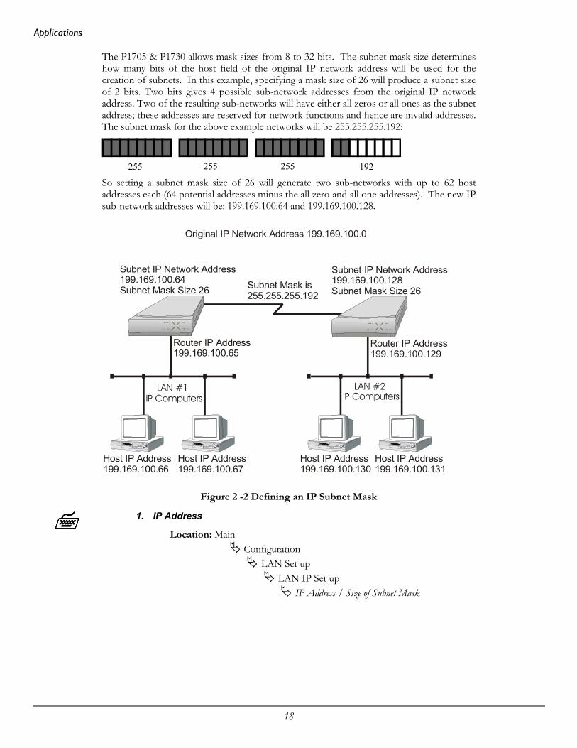
The P1705 & P1730 allows mask sizes from 8 to 32 bits. The subnet mask size determineshow many bits of the host field of the original IP network address will be used for thecreation of subnets. In this example, specifying a mask size of 26 will produce a subnet sizeof 2 bits. Two bits gives 4 possible sub-network addresses from the original IP networkaddress. Two of the resulting sub-networks will have either all zeros or all ones as the subnetaddress; these addresses are reserved for network functions and hence are invalid addresses.The subnet mask for the above example networks will be 255.255.255.192:
So setting a subnet mask size of 26 will generate two sub-networks with up to 62 hostaddresses each (64 potential addresses minus the all zero and all one addresses). The new IPsub-network addresses will be: 199.169.100.64 and 199.169.100.128.
Figure 2 -2 Defining an IP Subnet Mask
1. IP Address
Location: Main
Configuration LAN Set up
LAN IP Set up IP Address / Size of Subnet Mask
Original IP Network Address 199.169.100.0
Subnet IP Network Address199.169.100.64Subnet Mask Size 26
Router IP Address199.169.100.65
Host IP Address199.169.100.66
Host IP Address199.169.100.67
Host IP Address199.169.100.130
Host IP Address199.169.100.131
Router IP Address199.169.100.129
Subnet IP Network Address199.169.100.128Subnet Mask Size 26Subnet Mask is
255.255.255.192
IP Computers IP ComputersLAN #1 LAN #2

Applications
19
IP Default Gateway
An IP default gateway is an IP router that is resident on the local IP network that thisrouter is connected to and is used to route IP frames for destination networks that do notexist in the routing table. When an IP frame is received that is destined for a network that isnot listed in the routing table of the router, the router will send the IP frame to the defaultgateway. If the device originating the IP frame is on the same LAN as the router, the routerwill then send an ICMP redirect message to the originating device. Any future IP frames forthat destination network will then be sent directly to the default gateway instead of therouter.
A default gateway may be configured if there are a large number of routes that will passthrough another router to a larger network. An example of this would be a router that isused to connect to the Internet. All of the routers on the LAN would have the Internetaccess router as the default gateway.
IP Static Route
With its default settings, the P1705 & P1730 will automatically learn the routes to otherdevices on the network through RIP messages. In some instances it may be desirable tohave a predetermined or static route that will always be used to reach certain devices, such aswhen one specific router is to be used to reach a destination IP network. The static routewill have precedence over all learned RIP routes even if the cost of the RIP learned routes islower.
Edit Static Route
Location: Main
Configuration IP Routing Set-up
IP Routes Edit Static Route
Destination ( IP Address & Mask) Next Hop
Cost Add
Each static IP route is defined in the Edit Route menu. The destinationnetwork IP address is specified when you first enter the menu and then theIP address , alias or ID number of the next hop route and the cost may bedefined. Finally, select Add to add the route to the routing table.
Once static IP routes are defined, they may be viewed with the Show Static Routescommand from the IP Routes menu.
Configuration: When the IP routing protocol is set to none, static routes will be used to routeNote traffic. The mask size must also be defined when creating a static route entry. The subnet mask is required to allow a static route to be created to a different IP network address. See the previous section for an explanation of masks.
Applications
20
IPX RoutingThe P1705 & P1730 are pre-configured to operate as an IPX router. When installed in anIPX network, the router will learn the IPX network numbers from connected networks. Itwill then route the IPX frames to the appropriate destination IPX network.
The IPX routing scenario may consist of one of the two following configurations. The firstconfiguration consists of Novell servers located on each of the LAN segments to beconnected. The second configuration consists of Novell servers located on only one of theLAN segments to be connected. The router IPX router will need to be configureddifferently in the second configuration with Novell servers located on only one of the LANsegments.
Novell Servers in Both Locations
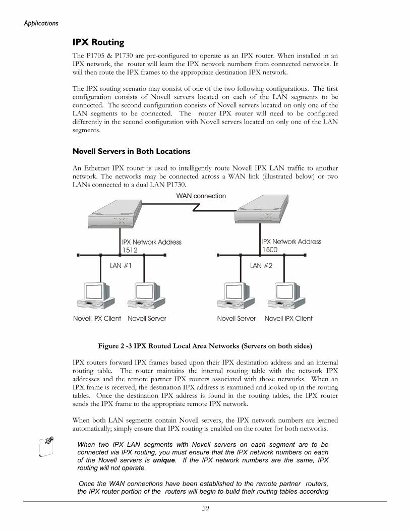
An Ethernet IPX router is used to intelligently route Novell IPX LAN traffic to anothernetwork. The networks may be connected across a WAN link (illustrated below) or twoLANs connected to a dual LAN P1730.
Figure 2 -3 IPX Routed Local Area Networks (Servers on both sides)
IPX routers forward IPX frames based upon their IPX destination address and an internalrouting table. The router maintains the internal routing table with the network IPXaddresses and the remote partner IPX routers associated with those networks. When anIPX frame is received, the destination IPX address is examined and looked up in the routingtables. Once the destination IPX address is found in the routing tables, the IPX routersends the IPX frame to the appropriate remote IPX network.
When both LAN segments contain Novell servers, the IPX network numbers are learnedautomatically; simply ensure that IPX routing is enabled on the router for both networks.
When two IPX LAN segments with Novell servers on each segment are to beconnected via IPX routing, you must ensure that the IPX network numbers on eachof the Novell servers is unique. If the IPX network numbers are the same, IPXrouting will not operate.
Once the WAN connections have been established to the remote partner routers,the IPX router portion of the routers will begin to build their routing tables according
WAN connection
Novell Server Novell Server Novell IPX ClientNovell IPX Client
LAN #1
IPX Network Address1512
IPX Network Address1500
LAN #2
Applications
21
to the IPX frames they receive from the network. Manual entries may be made in therouting tables by adding static IPX routes.
Novell Servers in One Location Only
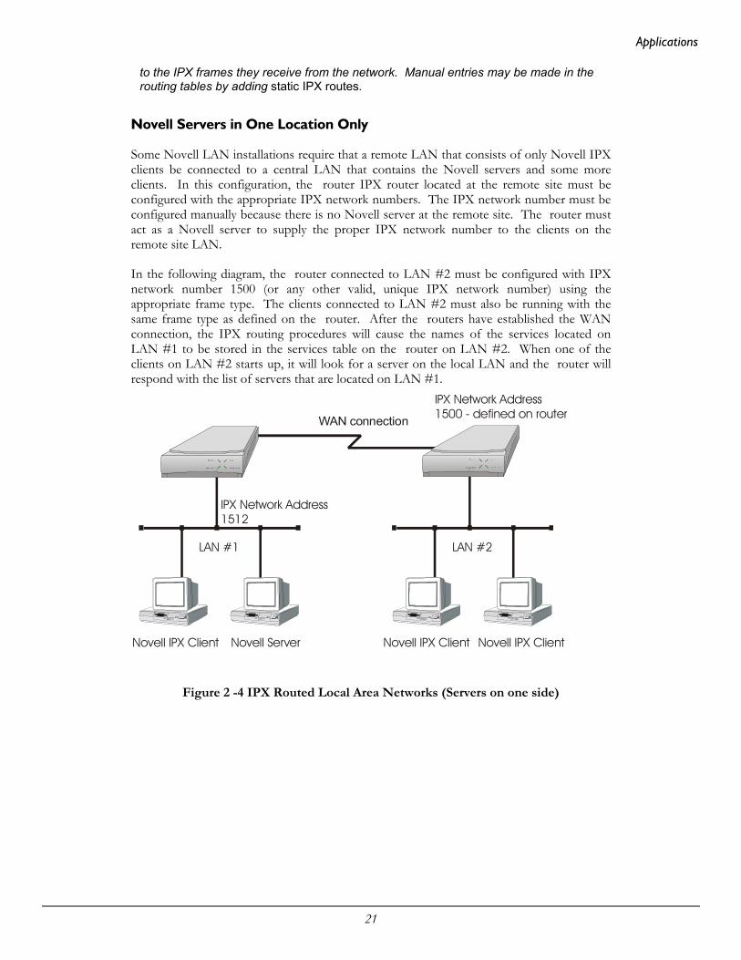
Some Novell LAN installations require that a remote LAN that consists of only Novell IPXclients be connected to a central LAN that contains the Novell servers and some moreclients. In this configuration, the router IPX router located at the remote site must beconfigured with the appropriate IPX network numbers. The IPX network number must beconfigured manually because there is no Novell server at the remote site. The router mustact as a Novell server to supply the proper IPX network number to the clients on theremote site LAN.
In the following diagram, the router connected to LAN #2 must be configured with IPXnetwork number 1500 (or any other valid, unique IPX network number) using theappropriate frame type. The clients connected to LAN #2 must also be running with thesame frame type as defined on the router. After the routers have established the WANconnection, the IPX routing procedures will cause the names of the services located onLAN #1 to be stored in the services table on the router on LAN #2. When one of theclients on LAN #2 starts up, it will look for a server on the local LAN and the router willrespond with the list of servers that are located on LAN #1.
Figure 2 -4 IPX Routed Local Area Networks (Servers on one side)
WAN connection
Novell Server Novell IPX ClientNovell IPX ClientNovell IPX Client
LAN #1
IPX Network Address1512
IPX Network Address1500 - defined on router
LAN #2

Applications
22
The following steps must be performed on the router connected to LAN #2.
IPX Routing Disabled
Location: Main
Configuration IPX Routing Set-up
IPX Routing
Disabling IPX routing allows the IPX frame types to be modified.
Configuration: IPX Routing does not need to be disabled in order to change the definedNote network numbers on a PPP router.
IPX Frame Types
Location: Main
Configuration LAN Set-up
LAN IPX Set-up Ethernet-II Frames RAW 802.3 Frames IEEE 802.2 Frames 802.2 SNAP Frames
Define the IPX network number for the appropriate frame type. Notethat IPX network numbers must be unique. If more than one frametype is to be used, each frame type must have a unique IPX networknumber. There must be no duplicate IPX network numbers within yourentire IPX routed network they must all be unique. The IPX networknumbers may be any value from 0 to FFFFFFFF HEX.
IPX Routing Enabled
Location: Main
Configuration IPX Routing Set-up
IPX Routing
IPX routing must be re-enabled to allow the router to operate as anIPX router with the newly defined IPX network numbers.
All connected router IPX routers must have IPX routing enabled forIPX routing to take place between the LANs. When one of the routerson a network has IPX routing disabled, all of the router IPX routers willbecome bridges only for IPX frames.

Applications
23
IPX Forwarding Enabled
Location: Main
Configuration IPX Routing Set-up
IPX Forwarding
IPX forwarding must be re-enabled to allow the router to forward IPXframes onto the WAN to the partner router IPX routers.
The IPX Forwarding function enables or disables the forwarding of IPX traffic whenIPX routing is enabled. When IPX forwarding is disabled, all IPX traffic across theWAN links will be blocked. While IPX forwarding is disabled, the router will stilloperate as an IPX router and maintain its routing and server tables.
.
Novell Server with Dual LANs
If an P1730 is configured with two LAN interface modules, the setup will be similar to theabove configuration; the difference being that rather than configuring the IPX numbers ondifferent routers, they are configured on different LANs.
IPX Frame Types
Location: Main
Configuration LAN Set-upselect LAN1 or LAN2
LAN IPX Set-up Ethernet-II Frames RAW 802.3 Frames IEEE 802.2 Frames 802.2 SNAP Frames
The configuration options described here are only for initial set-up and configurationpurposes. For more complete information on all of the configuration parameters availableplease refer to the P1705 & P1730 Menus Manual file on the accompanying CD-ROM.

Applications
24
PPP OverviewPoint to Point Protocol (PPP) is a connection protocol that allows control over the set-upand monitoring of network communications. It is used in procedures for user authentication(name and password), connection management (spoofing, bandwidth on demand, multilink),and compression. If any these functions are required on a frame relay connection, PPPencapsulation within frame relay is available.
PPP Link Configuration
A PPP connection between two routers may use a number of Network Control Protocols forcommunication. An IP router connection will use the Internet Protocol Control Protocol(IPCP) for all IP communications. An IPX router connection will use the Internet PacketExchange Control Protocol (IPXCP) for all IPX communications.
In order to establish an IPCP or IPXCP link connection between two PPP routers, either anumbered link or an unnumbered link connection must be established. The two types oflink connections are available to allow for greater flexibility between vendors products.
Numbered Links
A numbered link assigns a network address (either IP or IPX) to both ends of the WANconnection. In a numbered link configuration, the WAN connection may be viewed asanother LAN network with the two PPP routers simply routing information between theirlocal LANs and the common connected WAN network.
Because the WAN is considered a separate network, each of the stations on that networkmust be assigned a network address. If a numbered IP link is to be established, then eachWAN interface must be assigned an IP address on a unique IP network. The WAN IPnetwork address must be different from the two existing networks that are being connectedtogether with the PPP routers.
Location: Main
Configuration Connections Set-up
Remote Site Set-up Edit Remote Site
Protocol Set-up IP Parameters
Link IP address
If a numbered IPX link is to be established, then each WAN interface must be assigned anIPX node address on a unique IPX network number. The WAN IPX network address mustbe different from the two existing networks that are being connected together with the PPProuters.
The IPX node address of the local WAN link is defined as the Local IPX Node within theremote site profile settings. The IPX address of the WAN link of the remote PPP router isdefined as the Peer IPX Node within the remote site profile settings. The WAN IPXnetwork number is defined with the IPX Net option in the remote site profile settings.

Applications
25
Unnumbered Links
An unnumbered link does not use network addressing on the WAN link. The WANconnection is roughly equivalent to an internal connection with each of the two end pointrouters operating as half of a complete router that is connected between the two endpointLANs.
When an IPCP link is set to unnumbered, the only configuration option applicable is PeerIP Address. The peer IP address in this case is the IP address of the remote PPP router,that is the IP address of its LAN connection. If the peer IP address is not specified, therouter will attempt to determine it when negotiating the IPCP connection.
When an IPXCP link is set to unnumbered, no addressing configuration is required. All ofthe IPX settings are negotiated during the IPXCP connection.
When making a raw frame relay (no PPP encapsulation) connection withunnumbered links, the IP network address of each partner router must be manuallyentered in the remote site set-up for the link to operate.
Location: Main
Configuration Connections Set-up
Remote Site Set-up Edit Remote Site
Protocol Set-up IP Parameters
Peer IP address
Applications
26
Multilink Operation
Multilink operation defines the use of more than one link to connect between two PPProuters. The MultiLink Operation option of the remote site profile for a connection isenabled by default.
When a Multilink connection is established, the Multilink (MP) options within the PPP set-up and Advanced PPP set-up menus will determine the operation of the Multilinkconnection.
Location: Main
Configuration WAN Set-up
Remote Site Set-up Edit Remote Site
Protocol Set-up Multilink
Enabled

Applications
27
Basic WAN Configurations
Basic ISDN ConnectionsIf this P1705 & P1730 are configured as an ISDN bridge/router, it may establish WANconnections to other bridge/routers via ISDN (Integrated Services Digital Network)connections.
Before the P1705 & P1730 can establish an ISDN connection to another ISDN router, theISDN information must be defined. The ISDN switch type must be defined for the ISDNinterface, and the phone numbers must be defined. Refer to the following diagram thatshows three router units connected together with two ISDN B-channels being configuredon each unit.
Figure 2 -5 Basic ISDN Configuration
ISDNWAN connections
ISDN phone numbersassigned from theISDN circuit providerinformation.
555-1201
555-1202555-1301
555-1302
555-1101 555-1102

Applications
28
The following steps must be performed to configure the P1705 & P1730:
The default switch type for ISDN S/T interface modules is NET3, the default switch typefor ISDN U interface modules is NI-1. If the type of service your provider uses matches thedefault setting for the interface module, the following step may be skipped, otherwise, theswitch type must be set.
Switch Type
Location: Main
Configuration WAN Set-up
Switch Type
Ten ISDN switch types are available: net3, ni-1, ni-2, dms-100, 5ess-pp,5ess-mp, tph1962, kdd, sweden, or ntt. Note that if your routers arelocated within different ISDN jurisdictions, the ISDN switch type maybe different on each of the units.
Directory Numbers & SPIDs
Location: Main
Configuration WAN Set-up
Link Set-up ISDN Set-up
Directory Number SPID
The directory number will be the ISDN phone number used to establisha call between the routers. The SPID is used to register the ISDNinterface with the central switch.
For switch type NET3, only one directory number is required. The router will operatewithout putting in the directory number for a NET3 switch, but it is recommended thatit be entered.
Most North American installations use the switch type NI-1 and must have thedirectory number entered, as well the SPID (Service Profile Identifiers) value. For anNI-1 switch type, enter only the local portion of the directory number unless the areacode is required for local calls. The SPID must be set to the exact number given bythe ISDN service provider.

Applications
29
Once the ISDN switch type and directory numbers have been configured, the router mustbe reset for the new values to take effect and for the ISDN BRI interface to register with thecentral switch.
Soft Reset
Location: Main
Diagnostics Soft Reset
Once the router has restarted it is ready to establish ISDN connections.
With the ISDN numbers and switch type defined, an ISDN call may be placed to anotherproperly configured bridge/router. The calls may be placed manually or automatically. Theautomatic call features available are Auto-Call or IP Address Connect. An Auto-Callconnection is established each time the router starts up. An IP Address Connect call isestablished to a specifically configured remote router when certain IP traffic is receivedfrom the local LAN.
Note that any time the switch type is changed a soft reset must be performed before thechange will take effect.
The switch type is not saved through a full reset; the router will come up with the defaultswitch type – NET3; if you require a different switch type, it must be re-entered after aconfiguration reload. It is strongly recommended that the entire configuration set of therouter be saved (Dump config.txt to the console) then reloaded (Restore config.txt from theconsole) after a full reset.
The configuration options described here are only for initial set-up and configurationpurposes. For more complete information on all of the configuration parametersavailable, please refer to the “P1705 & P1730 Menus Reference Manual.PDF” onthe accompanying CD-ROM.

Applications
30
PPP ISDN Manual Call Quick Connections
The PPP P1705 & P1730 should be configured with a remote site profile entry for eachrouter that will be called (see section 2.3.1). A manual direct dial connection may beperformed to establish an initial connection to a remote site router. Once the connection isestablished and working properly, the remote site configuration for that router should beentered into the router. The remote site profile enables ISDN calls to be placedautomatically each time the router starts up (Auto-Call) or automatically depending uponthe time of day activation schedule or upon receiving IP frames from the local LANdestined for the IP network connected to that particular PPP router.

Applications
31
IPX Router Manual Call Connection
To establish an IPX PPP direct dial connection, enter the ISDN phone number of theremote site PPP router in the manual dial option. Refer to the Configure as an EthernetIPX Router section 2.3.1 for more information on IPX configuration required.
Manual Call
Location: Main
Configuration Connections Set-up
Remote Site Set-up Manual Call
Enter the ISDN phone number of the remote site IPX PPP router andan ISDN call will be placed.
IP Router Manual Call Connection
To establish an IP PPP direct dial connection, the IP addresses must be supplied for thisdevice before the ISDN call may be placed. Refer to the Configure as an Ethernet IP Routersection 2.1.2 for more information on the IP configuration required.
IP Address
Location: Main
Configuration LAN Set-up
LAN IP Set-up IP Address / Subnet mask size
Manual Call
Location: Main
Configuration Connections Set-up
Remote Site Set-up Manual Call
Enter the ISDN phone number of the remote site IP PPP router and an ISDN call will beplaced.

Applications
32
Basic Frame Relay ConfigurationNorth American P1705 & P1730 with at least one non-ISDN interface are configured tohave frame relay enabled for that interface by default. P1705 & P1730 shipped outside ofNorth America with at least one non-ISDN interface will have frame relay disabled on thatinterface as a default setting. See the following page for instructions on switching Framerelay from disabled to enabled.
If the P1730 or P1705 is configured as a frame relay router, it will communicate over WANconnections to other Frame Relay units via Frame Relay Permanent Virtual Circuits (PVC).From 1 to 128 PVC’s may be defined to connect to other frame relay units. Before theP1730 or P1705 can establish a PVC connection to another frame relay router, at least onePVC must be defined. The router is pre-configured to query the frame relay service to auto-learn the required parameters; they may also be set manually.
The DLCI (Data Link Connection Identifier) number for the PVC is assigned by the framerelay service provider. The PVC must be defined on at least one physical links on therouter. Refer to the following diagram that shows three router units connected togetherwith two PVCs being configured on each unit. The configuration of the PVCs within theframe relay cloud is controlled by the frame relay service provider.
Figure 2 -8 Frame Relay configuration
Frame Relay PVCWAN connections
DLCI numbersassigned for thesePVCs from theframe relay provider.
50
51
52 53
54 55
Applications
33
Configuration: The default configuration for P1705 & P1730 shipped outside NorthAmerica is to have frame relay disabled. To run frame relay on theserouters, it must first be enabled. Selecting the Frame Relay option willtoggle the setting from disabled to enabled.
Frame Relay enable
Location: Main
Configuration WAN Set-up
Link Set-up Frame Relayenabled
The router will request confirmation of the change, enter “yes”.
For an P1705 & P1730 with a CSU-DSU interface, the default clock speed that the P1705 &P1730 will expect to receive from the DCE link is 64Kbps. If the DCE link is 56 Kbps, thenthe Link Speed value must be reset to 56 here.
Link Speed
Location: Main
Configuration WAN Set-up
Link Set-up Link Speed56
Auto Learning the Frame Relay Configuration
The P1705 & P1730 are pre-configured to query the frame relay service to auto-learn theLMI type and the PVC DLCI numbers. This auto-learn function allows the P1705 &P1730 to be plugged into the frame relay service and auto-learn the PVC configuration tobecome operational without further manual configuration. router auto-learning conformsto RFC1490.
Manual configuration is also allowed by modifying the options within each Remote SiteProfile and the individual link configuration menus.
When the P1730 or P1705 first starts up it will query the frame relay service to try todetermine the LMI type on each of the frame relay links. Once the LMI type isdetermined, the PVC configurations will be known from the full status enquiry messages.If the DLCI numbers of the PVC’s on your service are determined during this learningprocess, the router will automatically create a remote site profile for each PVC. Theautomatically created remote site profiles will be named “LinkxDLCIyyy” where x is thephysical link number the PVC is on and yyy is the DLCI of the PVC.

Applications
34
If during this learning process the maximum number of remote sites has beenreached, the router will prompt you that there are no remote sites available. A newremote site cannot be auto-created unless one of the existing remote sites ismanually deleted.
Auto-learning with PPP encapsulation enabled (see following page) may not becompatible with some older model routers. If problems with auto-learning occur withPPP enabled, try disabling PPP encapsulation.
Manual Configuration - LMI Type
The LMI Type option allows you to manually specify the type of Link ManagementInterface in use by the Frame Relay service provider for the Frame Relay service.
When the LMI type is set to none, the router simply creates frame relay packets andsends them on the defined PVC’s. The links are not checked for errors. There is nocongestion control checking. The link is only monitored for control signals.
To manually configure the LMI type the Auto-Learning option must be disabled.
Auto-Learning
Location: Main
Configuration WAN Set-up
Link Set-up Frame Relay Set-up
Auto-learningEnabled
LMI Type
Location: Main
Configuration WAN Set-up
Link Set-up Frame Relay Set-up
LMI Type
The configuration options described here are only for initial set-up and configurationpurposes. For more complete information on all of the configuration parametersavailable please refer to the “P1705 & P1730 Menus Reference Manual” file on theaccompanying CD-ROM.
Applications
35
Quick Start Frame Relay
Since the P1705 & P1730 auto-learns the frame relay configuration, only a couple ofparameters need to be configured before the unit is fully operational as an IP router forframe relay.
Upon initial start up, the P1705 & P1730 are pre-configured to query the frame relayservice to auto-learn the LMI type and the PVC DLCI numbers. The P1705 & P1730will then automatically create a remote site profile for each PVC.
Within each of the remote site profiles automatically created Bridging, IP routing, andIPX routing are all set to “enabled”. Because each of these options are enabled by defaultand the automatically created remote site profiles will establish a PVC connection to theremote site routers, the P1705 & P1730 will bridge and IPX route data without any userconfiguration. Because an IP router requires an IP address, the router must beconfigured with an IP address before IP routing is fully operational.
To configure an IP address for the P1705 & P1730, use the IP address option.
IP Address
Location: Main
Configuration LAN Set-up
LAN IP Set-up IP Address / mask size
If security is required for the PVC connection refer to the Configure PPP Security sectionfor information on setting the security passwords and user names for PPP.
By default, PPP is disabled for each of the newly created remote site profiles. If PPPencapsulation is desired, for example to use security, the PPP encapsulation optionshould be set to “enabled”. By default, when PPP encapsulation is enabled multilink isalso enabled.
PPP Encapsulation
Location: Main
Configuration WAN Set-Up
Remote Site Set-Up Edit Remote Site Connection Set-up
PPP Enabled

Applications
36
Basic Leased Line ConfigurationThe P1705 & P1730 establishes PPP (Point to Point Protocol) WAN connections to otherPPP Leased Line routers or to other vendors PPP leased line routers via direct leased lineconnections. Either 1 or 2 links may be used to connect to other PPP routers.
Configuration: The default configuration for P1705 & P1730 shipped within NorthAmerican with at least one non-ISDN interface module, is to have frame relayenabled on that interface. To run PPP leased line, frame relay must be disabled.Selecting the Frame Relay option will toggle the setting from enabled to disabled.
Frame Relay disable
Location: Main
Configuration WAN Set-up
Link Set-up Frame Relaydisabled
The router will request confirmation of the change, enter “yes”.
Quick Start PPP Leased Line Connections
A Quick Start minimal configuration may be used to initially establish a connection toanother vendors PPP router. Once the connection is established and is working properly,the router should be configured with a remote site profile entry for that vendors router.
Before the P1705 & P1730 can establish a link connection to another PPP router, the linkspeed information must be defined. Refer to the following diagram that shows two routersand another vendors unit connected together with direct leased line connections.
Figure 2 -9 Basic PPP Leased Line Configuration
PPP IP Router

Applications
37
The following steps must be performed on each of the routers in the network.
Local IP Address
Location: Main
Configuration LAN Set-up
LAN IP Set-up IP Address / mask size
This is the IP address and subnet mask for the link of this router in theunnumbered IP connection.
Usually the clocking signal is received from the link (see Appendix D -Link Clocking Information). If the link interface is a V.11, V.35 orRS232 connection and the link speed is different from the default(64Kbps), and the router is to be the clock source, the link speed mustbe set to the clock speed that the router receives from the DCE linkdevice.
Link Speed
Location: Main
Configuration WAN Set-up
Link Set-up Link Speed
Bridge Connection
Once the link speeds have been configured, the router will attempt to establish the linkconnection to the remote site PPP router. The Bridge connection does not require anyconfiguration for operation.
IP Router Connection
Once the link speeds and local IP address have been configured, the router will attempt toestablish the link connection to the remote site PPP router. The IP connection is anunnumbered connection that requires only the configuration of the IP address of therouter.
IPX Router Connection
Once the link speeds have been configured, the router will attempt to establish the linkconnection to the remote site PPP router. The IPX connection is an unnumberedconnection that does not require any configuration.
If security is required for the direct dial connection refer to the Configure PPP Security sectionfor information on setting the security passwords and user names for PPP.

Applications
38
Configure Remote Site Profiles
Remote Site Profiles allow the router to have different sets of configuration parameters foreach of the remote site routers that may be called or that may call this router. This allowscomplete control over the configuration of each possible connection.
Each remote site profile is assigned an identification number when it is created, whether it iscreated automatically under auto-learning or manually by the user editing the remote siteprofile. The remote site is also named with an alias, which provides a more descriptiveidentifier for the remote site profile. For example, a remote site profile may be created witha name that describes the location of the remote router or a user name on an incomingconnection. The alias may be up to 16 characters long and must begin with an alphabeticcharacter (blanks and the character ”!” are not allowed).
There can be up to 128 remote site profiles. The ID numbers are assigned automatically inascending order as the site profiles are created.
ID numbers 129, 130 and 131 are templates for creating remote site profiles with ISDN.Frame Relay or Leased Line connections respectively. A template may have its parametersset to match common network configurations and then be used to quickly set-up a new site.In addition to the reserved templates, you can use any remote site as a template to create anew site.
The remote site profile allows the definition of various connection parameters: Circuit set-up, Bridge and Routing protocol configuration, activation criteria and security.
The following steps must be performed on the P1705 & P1730 in order to define a newremote site profile.
Remote Site Profile ID & Alias
Location: Main
Configuration WAN Set up
Remote Site Set-up Edit Remote Site
The remote site alias must be entered. The remote site profile is thencreated, an ID number is automatically assigned to it and the remote siteprofile is opened for editing. If a remote site profile already exists, eitherthe ID number or the alias may be provided to access the site profile forediting.
Applications
39
Configure Remote Site Profiles for ISDN PPPIf this router is configured to have at least one ISDN switched circuit, the ISDN callparameters must be defined so that the router knows what ISDN phone number to dialwhen a connection to this remote site is required and what security parameters to use whenestablishing a connection.
When this router receives an ISDN connection it will prompt the calling device for a username and password (PPP access security); once the name and password have beenauthenticated, the user name is used to search the remote site profile entries to find a match.Once a match is found, the configuration parameters defined within that remote site profileare used to finish establishing the PPP connection. For example, if this router receives anISDN call from another device and in response to the user name prompt receives the name“Calgary”, it will look in the remote site list for a profile with the alias “Calgary”. If the“Calgary” profile is found, the parameters in it will be used for password authentication andcompletion of the connection. If there is no match for the user name “Calgary”, the call willbe rejected.
The remote site profile alias, user name of the security entry, and the username defined on the partner PPP router must all be the same for theconnection to be established.
Remote Site ISDN Phone Number
Location: Main
Configuration WAN Set up
Remote Site Set-up Edit Remote Site
Connection Set-up ISDN Call Set-up
ISDN Number
The ISDN number defined here is the ISDN phone number of theremote site ISDN PPP router. This is the ISDN phone number that willbe dialed to establish a connection to this remote site profile. Aconnection to this remote site may be established by one of thefollowing methods:
1 a) Using the Manual Call option of the Remote Site set-up menu, Location: Main
Configuration WAN Set up
Remote Site Set-up Manual Call

Applications
40
1 b) Defining this remote site profile within the IP Address connect table, which willcause a call to be made when a packet for this IP address is routed, Location: Main
Configuration WAN Set up
IP Address Connect IP Address Connect
Enabled
1 c) Defining the Auto-Call option within the Edit Remote Site menu of this remote siteprofile. (The Auto-Call option causes the router to attempt to establish a connectionto this remote site profile each time the router starts up.) Location: Main
Configuration WAN Set up
Remote Site Set-up Edit Remote Site
Connection Set-up Auto call
Enabled
1 d) Setting up an activation schedule with times the connection is to be activated anddeactivated Location: Main
Configuration WAN Set up
Remote Site Set-up Edit Remote Site
Activation ScheduleActivation intervals
1 e) If a second ISDN channel is available and traffic level is enabled, setting the trafficload at which the second channel is to be activated. Location: Main
Configuration WAN Set up
Remote Site Set-up Edit Remote Site
Activation Threshold
Up ThresholdDown ThresholdUp Stability timerDown Stability timer

Applications
41
Configure Remote Site Profile for Frame RelayEach of the PVC’s on the frame relay service must be configured within an individualremote site profile on the router. This is usually done automatically through the auto-learning process. When the frame relay router first starts up it will query the frame relayservice to try to determine the PVC configurations. If the DLCI numbers of the PVC’son your service are determined during startup, the router will automatically create aremote site profile for each PVC. The automatically created remote site profiles will benamed “LinkxDLCIyyy” where x is the physical link number the PVC is on and yyy is theDLCI of the PVC.
If during this learning process the maximum number of remote sites has beenreached, the router will prompt you that there are no remote sites available. A newremote site cannot be auto-created unless one of the existing remote sites ismanually deleted.
These automatically created remote site profiles may be renamed for easier identificationor usage by changing the Remote Site Alias.
Remote Site Profile Alias
Location: Main
Configuration WAN Set up
Remote Site Set-up Edit Remote Site
Remote Site Alias
Configuration: When configuring the router to use PAP or CHAP security Note authentication, after the router has automatically created remote site profiles for each of the PVC’s, either the remote site profile alias must be changed to match the Outgoing User Name configured on the remote site router or vice versa. If the local remote site alias and the remote site routers
outgoing user name do not match, the PVC will always fail with a security violation. Also note that PPP encapsulation must be enabled to run security access authentication.
With auto-learning, the above is all that is required of the user to set-up frame relayremote site profiles. If desired, parameters may be entered manually as follows:
Each PVC defined on this router must have a DLCI (Data Link Connection Identifier)value assigned for proper frame relay communication.
DLCI
Location: Main
Configuration WAN Set up
Remote Site Set-up Edit Remote Site
Connection Set-up DLCI

Applications
42
The DLCI number defined here is the Data Link Connection Identifiervalue provided by your frame relay service provider. This value must beset if auto-learning is disabled.
Each Remote Site PVC must be defined to exist on one of the two physical WAN linksavailable on this router.
Primary Link
Location: Main
Configuration WAN Set up
Remote Site Set-up Edit Remote Site
Connection Set-up Primary Link
The Primary Link value defines to which of the two physical WAN linksthat this PVC will be assigned. This value must be set.
Two other values must be set before the remote site profiles are fully configured, the CIRand EIR. The Committed Information Rate (CIR) option specifies the data rate that theFrame Relay service has guaranteed to provide. The Excess Information Rate (EIR)option specifies the data rate that the Frame Relay service indicates may be available forthis PVC.
CIR
Location: Main
Configuration WAN Set up
Remote Site Set-up Edit Remote Site
Connection Set-up CIR
The CIR value specifies the guaranteed data rate for this PVC. Thisvalue must be set to the same as the value provided by the Frame Relaynetwork provider. The value of 0 indicates that there is no commitmenton the data rate.
Configuration: When changing the CIR option for this PVC, the PVC must be disabled andNote then enabled before the new value will take effect.

Applications
43
EIR
Location: Main
Configuration WAN Set up
Remote Site Set-up Edit Remote Site
Connection Set-up EIR
The EIR value specifies the indicated data rate that may be available for thisPVC. This value must be set to the same as the value provided by theFrame Relay network provider. When EIR = 0, no excess burst data isallowed to be transmitted. If EIR is non-zero, bursting is allowed. The onlyrestriction is that CIR + EIR > 0.
Configuration: When changing the EIR option for this PVC, the PVC must be disabled andNote then enabled before the new value will take effect.
The Bridge, IP, IPX, and Compression settings may now be configured within the Bridge,Parameters, IP Parameters, IPX Parameters, and CCP Parameters menus (note:compression over frame relay is only available if PPP encapsulation is enabled).
If either the Bridge portion or the IP or IPX router portion of the connection is notrequired, the appropriate Connection Protocol setting must be disabled within theappropriate sub-menu. For example; if an IPX only connection is to be established, theBridging and IP parameters must be disabled so that the router does not negotiate theBridge or IP Connection Protocols on the connection.
Connection Protocol Setting
Location: Main
Configuration WAN Set up
Remote Site Set-up Edit Remote Site
Protocol Set-up Bridge Parameters
Bridge enabled disabled
IP Parameters IP enabled
disabled
Disabling a particular connection protocol option will prevent therouter from negotiating that Network Connection Protocol. Leaving alloptions enabled will result in a Bridge, IP router, and IPX routerconnection.

Applications
44
Configure Remote Site Profiles for Leased Line PPPRemote Site Profiles allow the router to have different sets of configuration parameters foreach of the possible remote site PPP routers that may be connected to this router. Thisallows greater control over the configuration of each possible PPP connection.
Each remote site profile is named with an alias. The alias provides a simple method ofmaintaining configuration control over the remote site profiles defined. For example, aremote site profile may be created with a name that describes the location of the remotePPP router. The alias also provides a method of matching a remote site profile and itsconfiguration settings to a particular user name on an incoming connection. When a PPPsecurity user name is defined the same as one of the remote site profiles, that remote siteprofile will be used for PPP negotiations after the security authentication process has passed.In other words, when this router receives a link connection attempt it will prompt theremote device for a user name and password (PPP security). Once the name and passwordhave been authenticated, the user name is used to search the remote site profile entries tofind a match. Once a match is found, the configuration parameters defined within thatremote site profile are used to finish establishing the PPP connection.
The outgoing user name in the remote site security parameters entry, and the remotesite alias defined on the partner PPP router must be the same to allow for properoperation.
The following steps must be performed on the P1705 & P1730 in order to define a newremote site profile.
Remote Site Profile ID & Alias
Location: Main
Configuration WAN Set up
Remote Site Set-up Edit Remote Site
The remote site alias must be entered to create a new site. If a userdefined remote site profile already exists, only the id number needs to beprovided to edit that site’s parameters.

Applications
45
Now that the remote site profile is created, a link number must be assigned as the primarylink number. The primary link number is the link interface that the router will use toattempt to establish a connection to the remote site PPP router.
Primary Link Number
Location: Main
Configuration WAN Set up
Remote Site Set-up Edit Remote Site
Connection Set-up Primary Link
The Primary Link number defined here is the link interface used toestablish the connection to the remote site PPP router. When a linknumber is defined within a new remote site profile, that link number willbe removed from any remote site profile that originally was defined touse the link. The link will then be used within the newly defined remotesite profile.
When this remote site profile is defined to use Multilink protocol, theSecondary Connection should also be defined.
The Bridge settings may now be configured within the Bridge Parameters menu.
The IP settings may now be configured within the IP Parameters menu.
The IPX settings may now be configured within the IPX Parameters menu.
The Compression settings may now be configured within the CCP Parameters menu.
The configuration options described here are only for initial set-up and configurationpurposes. For more complete information on all of the configuration parametersavailable please refer to the PPP Menu Reference Manual file on the accompanying CD-ROM.

Applications
46
Configure Remote Site Profiles for Frame Relay with ISDN backupFrame Relay operation is set-up as described in section 2.3.2
The PVC on both partner routers must be disabled during this set-upprocedure, then re-enabled when ready to start.
ISDN call set-up is done as described in section 2.3.1.
Recovery operation is set-up on the secondary activation menu.
If the ISDN circuit is to be available only at specified times, rather than all thetime (the default), set-up a recovery schedule with times the connection is tobe activated and deactivated
Activation Schedule
Location: Main
Configuration WAN Set up
Remote Site Set-up Edit Remote Site
Connection Set-up Activation
Schedule
Enter “a” and the times the recovery circuit is to be made available, enter “d”and the times the recovery circuit is to be deactivated.
Enable the secondary activation circuit for recovery
Recovery
Location: Main
Configuration WAN Set up
Remote Site Set-up Edit Remote Site
Connection Recovery
The recovery schedules MUST be set identically on both partner PPP routersto operate; if they are not, one router will try to bring the link up and the otherwill shut it down.

Applications
47
Configure Remote Site Profiles for PPPoERemote Site Profiles allow for the router to be configured to support PPP over Ethernet(PPPoE) client on the router. The PPPoE feature on the Perle routers provide a PPPoEclient support on Ethernet interfaces to a bridging DSL modem to the Internet. This featurewill create a PPP tunnel to an ISP located somewhere on the ATM network side of thexDSL modem. This feature eliminates the hassle and potential error of running a PPPoEclient on each LAN workstation that requires Internet access. This feature is only availableon the Perle 1730 model.
The following steps must be performed in order for the router to be configured for PPPoEconnection. The remote site set-up for the PPPoE should refer to the section for ConfigureRemote Site Profiles for Leased Line PPP as the initial guideline for setting up a remote siteconfiguration for PPP. Afterwards the following steps transform the PPP remote siteconnection to a unique PPPoE remote site configuration.
Location: Main
Configuration
WAN Set-Up Remote Site Set-up
Edit Remote Site Connection Set-up
Primary Link LAN
The Primary Link options will display two options LAN1 and LAN2 if the unit detects thesecondary LAN Interface module installed.
The Auto-Call field will be automatically setup to be enabled when a LAN interface isselected as the primary link. This will allow the PPPoE connection to be establishedautomatically upon boot-up of the router.
To verify that PPPoE is enabled for this remote connection, view the read-only parameter
Location: Main
Configuration
WAN Set-UPRemote Site Set-Up
Edit Remote SiteProtocol Set-Up
PPPoEenabled
When setting up your PPPoE link with your ISP provider, one global IP addresses will beprovided that should be used for the PPPoE remote site configuration. By enabled theNAT feature on the remote site configuration allows you to maintain only one global IPaddresses for all PC workstation on your internal LAN.

Applications
48
Location: Main
Configuration WAN Set-up
Remote Site Set-Up Edit Remote Site
Protocol Set-Up IP Set-up
NAT enabled enabled
Access to some web pages is a common problem experienced when running a PPPoE clienton a router. By design, PPPoE packets can support a maximum MTU of up 1492 bytes.Normally when a connection is established over common PPP, the TCP protocol negotiatesits maximum data size using the mss option (default 1460). By default, most Windows PCshave their TCP mss option set to 1460 bytes. Since PPPoE requires an additional 8 bytes ofheader data, the TCP mss option should decrease to 1452 bytes. Therefore whenconfiguring the router for PPPoE, the remote site NAT configuration automatically adjustits TCP mss option to 1452 to accommodate this requirement. To verify this value has beenadjusted:
Location: Main
Configuration
WAN Set-UpRemote Site Set-up
Protocol Set-UpIP Parameters
NAT Advanced Set-upTCP mss
enabledTCP mss value
1452

Applications
49
Normally your ISP provider will provide you with an outgoing username and password andto authenticate with their services. The PPPoE remote site configuration needs to have thesecurity section configured with this ISP parameters to authenticate the PPPoE connection.
Location: Main
Configuration
WAN Set-UpRemote Site Set-Up
Security Set-UpOutgoing Username
ISP provided usernameOutgoing PAP password
ISP provided passwordOutgoing CHAP password (if required by ISP)
ISP chap password
To ensure that network traffic is routed to the PPPoE connection, the router must beconfigured to have the default IP gateway setup to your newly created PPPoE remote siteconnection.
Location: Main
Configuration
IP Routing Set-upGateway
PPPoE remote site alias

Applications
50
Advanced Features
Configure Dynamic Host Configuration ProtocolThe P1705 & P1730 use Dynamic Host Configuration Protocol (DHCP) to allow users in asmall office environment to be added and removed from a network with all of the networkinformation (i.e. IP address, DNS, subnet mask, etc.) being configured automatically. DHCPconfigures devices (DHCP clients) from a central DHCP server. It is designed to allocatenetwork addresses to a number of hosts on the router’s LAN and supply the minimalconfiguration needed to allow hosts to operate in an IP network.
The following steps must be performed on the P1705 & P1730 to configure it as a DHCPserver.
DHCP Services
Location: Main
ConfigurationApplications Set-up
DHCP Set-up DHCP Services
Server
DHCP Services options which are available are none, relay and server.Set to server to enable this device as a DHCP Server.
IP Address Pool
Location: Main
Configuration Applications Set-up
DHCP Set-up Server IP address pool
IP address pool IP Address / number of addresses
The IP address pool option requires setting the first IP address in therange that is to be used for the devices attached to the DHCP Server.The number of addresses to be assigned must also be specified, to amaximum of 253.
When setting up a router as a DHCP server, you may not assign an addresspool that includes broadcast addresses (all ones in the host portion of the IP
address) for known networks. Known networks include any local networksplus standard A, B and C class addresses.
With the DHCP Services and IP Address Pool defined, devices may be attached to thenetwork (up to the maximum specified) and they will be automatically configured.
When setting up a router as a DHCP server that will have both a DNS serveron the internal network and a remote connection to another DNS server (for
example, through an ISP), then the local DNS server should be set as theprimary DNS and the external DNS server as the secondary DNS.
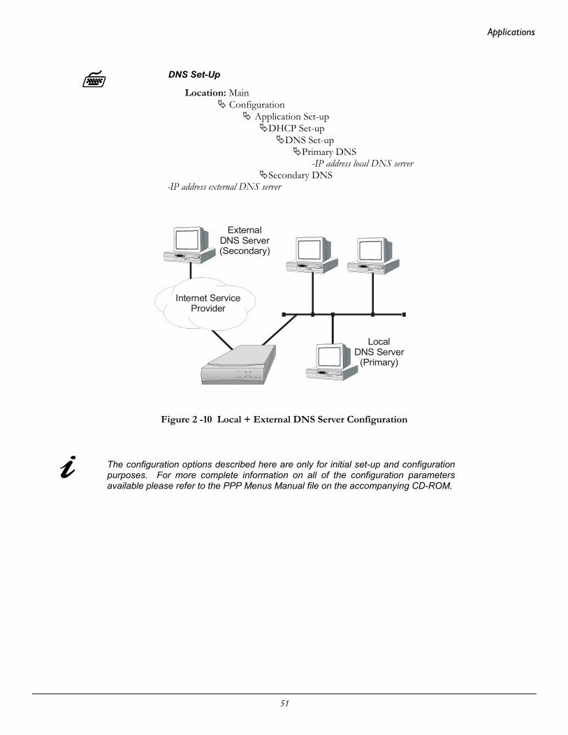
Applications
51
DNS Set-Up
Location: Main Configuration
Application Set-upDHCP Set-up
DNS Set-upPrimary DNS
-IP address local DNS serverSecondary DNS
-IP address external DNS server
Figure 2 -10 Local + External DNS Server Configuration
The configuration options described here are only for initial set-up and configurationpurposes. For more complete information on all of the configuration parametersavailable please refer to the PPP Menus Manual file on the accompanying CD-ROM.
Internet ServiceProvider
Local DNS Server
(Primary)
External DNS Server(Secondary)

Applications
52
Network Address Translation and Port TranslationThe P1705 & P1730 provide support for Network Address Translation (NAT). NetworkAddress Translation is a technique that translates private IP address on a private network tovalid global IP addresses for access to the Internet. Network Address Port Translation(NAPT) translates both the IP address and the port number. The advantage of porttranslation is that more than one private IP address can be translated to the same global IPaddress. Port translation allows data exchanges initiated from hosts with private IPaddresses to be sent to the Internet via the router using a single global IP address. A globalIP address must be assigned to the WAN link upon which NAPT is enabled for porttranslation to work. The global IP address will be assigned by the ISP.
To use NAPT, the private network addresses of the services that will be available globallymust be assigned:
NAT Exports
Location: Main
Configuration Applications Set-up
NAT Exports Edit Services
enter the private network IP address of each service offered
Then NAT (Network Address Translation) is enabled:
NAT Enable
Location: Main
Configuration WAN Set-up
Remote Site Set-up Edit Remote Site
Protocol Set-up IP Parameters
NAT EnabledEnabled
Configuration: When running frame relay RAW 1490, the local IP address and peer router IPNote address must be set in the IP parameters menu.
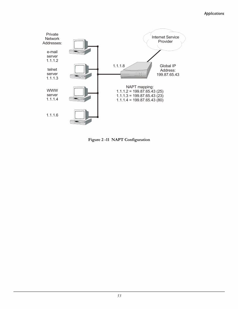
Applications
53
Figure 2 -11 NAPT Configuration
Internet ServiceProvider
Private Network
Addresses:
Global IPAddress:
199.87.65.43
NAPT mapping:1.1.1.2 = 199.87.65.43 (25)1.1.1.3 = 199.87.65.43 (23)1.1.1.4 = 199.87.65.43 (80)
e-mailserver1.1.1.2
telnetserver1.1.1.3
WWWserver1.1.1.4
1.1.1.6
1.1.1.8
Applications
54
SecurityThe router provides a number of means of providing security on incoming and outgoingtraffic on a network. These methods include access password authentication, firewalllimiting access to only designated device addresses, private network address translation(NAT) and filtering for both incoming and outgoing traffic.
Configure PPP Security
The PPP P1705 & P1730 provide support for both PAP and CHAP security accessauthentication. An outgoing user name, PAP password, and CHAP secret are defined thatthe router will use when responding to an authentication request from a remote site PPProuter.
The cold start defaults for the security user name and passwords are as follows.These defaults will exist when the router is first started before and configuration isentered, and after a Full Reset has been performed. These default values are alsoset when the router is placed in TFTP Network load mode for upgrading theoperating software via TFTP transfers. Care should be taken when upgrading agroup of routers that have security levels set.
Default outgoing user name for each remote site when it is defined is the same asthe default device name. Default PAP password and CHAP secret are both set to“BRIDGE”.
The complete password security configuration for both incoming and outgoing calls isdefined within the Security menu of the WAN set-up section.
Security Level
Location: Main
Configuration WAN Set-up
Security Set-up Security Level
The security level defines the type of security that this router willrequest when a remote site PPP router attempts to establish a PPPconnection. The security may defined as none, PAP, or CHAP.
When a security level is defined on this router, an entry for each remote site PPP router thatmay be connected to this router must be placed in the security database. The securitydatabase is used to store the user names and passwords of the remote site PPP routers.

Applications
55
Remote Site Security Parameters Entry
Location: Main
Configuration WAN Set up
Edit Remote Site Security Parameters
Outgoing User Name Incoming PAP Password
Outgoing PAP Password
or Incoming CHAP Secret Outgoing CHAP Secret
The outgoing entries in the security database define the user names andpasswords/secrets that this router will send in response to anauthentication request is sent from the remote partner router. Theincoming entries define the passwords/secrets that this router expectsto receive from the remote partner in response to authenticationrequests.
For a pair of partner routers with security enabled, the outgoing user name in thesecurity parameters entry of one router must match the remote site alias in thepartner router’s remote sites table.
To use PPP security with frame relay, PPP encapsulation must be enabled. ThePVC must be disabled to change the PPP encapsulation status, then re-enabled.
The configuration options described here are only for initial set-up and configurationpurposes. For more complete information on all of the configuration parametersavailable please refer to the P1705 & P1730 Menus Manual file on theaccompanying CD-ROM.

Applications
56
Configure Firewall
The P1705 & P1730 provide Firewall security for restricting access between any twonetworks connected through the router. Firewalls are set-up on a per connection basis forthe LAN and remote sites. The direction of filtering is from the perspective of the router;incoming traffic is from the network in question to the router, outgoing is from the routerto the network. The direction of filtering may be set to incoming, outgoing, both or none.Once the direction of filtering for a connection has been set, holes may be created in thefirewall to allow specified traffic through. Normally, the LAN firewall is used for restrictingintranet traffic (connections within the corporate network) and remote site firewalls are used tolimit access from less trusted sources, such as the Internet or dial-up ISDN links.
The following diagram shows a corporate head office network, which is connected, to theInternet with an router. There is also a branch office at a remote site connected with aleased link. The administrator at the corporate head office wishes to set-up an IP firewall toallow everyone on the Internet to have access to the corporate FTP and Web servers andnothing else. The administrator also wishes to allow all of the TCP traffic from the branchoffice network to have access to the head office. Anyone in the corporation may haveunrestricted access to the Internet.
Figure 2 -13 Sample Firewall Application
The following steps must be performed on the P1705 & P1730 to set-up the firewallsupport as desired.
Internet
Router with firewall enabled.
Corporate HeadOffice Network195.100.1.0
Branch Office Network195.100.2.0
Any other networkany IP address
Main FTP server: 195.100.1.12Main Web server: 195.100.1.20
Applications
57
First the firewall on the ISP connection (remote site 1) of the WAN is set-up. The firewalloption is set to “inbound” to have this WAN firewall filter traffic from the ISP to therouter while allowing unrestricted access out to the Internet.
Firewall
Location: Main Configuration
Applications Set-up Firewall Set-up
WAN Firewall Set-up enter ID# 1 for ISP remote site Firewall
inbound
The firewall on the Internet connection is set-up to protect the entire corporatenetwork, including the branch office, from unauthorized traffic.
Then the entries are made in the “Designated Servers” menu to allow Internet access to theFTP and Web servers on the corporate network.
FTP & WWW Designated Servers
Location: Main Configuration
Applications Set-up Firewall Set-up
WAN Firewall Set-up ID# 1 for ISP remote site Designated Servers
FTP Server— 195.100.1.12
WWW (HTTP) Server— 195.100.1.20
When defining a designated server you will be prompted for the IPaddress of that device. Adding an entry to the designated servers listallows you to quickly setup a firewall entry without having to figure outTCP port values.
Next, the LAN firewall is set-up to restrict access to the LAN. The firewall option is set to“outbound” to have the LAN firewall filter traffic from the router.
Firewall
Location: Main Configuration
Applications Set-up Firewall Set-up
LAN Firewall Set-up Firewall
Outbound
Note: if this P1730 has a second LAN interface installed, you will be requested to selectwhich LAN this firewall entry is to be used with.

Applications
58
Then an entry is placed in the firewall table to allow the devices in the branch office remotesite to have unlimited TCP access to devices in the head office.
Firewall Table Entry
Location: Main Configuration
Applications Set-up Firewall Set-up
LAN Firewall Set-up Edit Firewall Entry
filter ID # 1 Destination Address
— 195.100.1.0 Destination Mask
— 255.255.255.0 Source Address
— 195.100.2.0 Source Mask
— 255.255.255.0 Protocol Type
— TCP Entry Direction
— outbound
Finally, holes are provided in the LAN firewall to allow Internet access to the FTP andWWW servers
Firewall
Location: Main Configuration
Applications Set-up Firewall Set-up
LAN Firewall Set-up Designated Servers
FTP Server— 195.100.1.12
WWW (HTTP) Server— 195.100.1.20
The configuration options described here are only for initial set-up and configurationpurposes. For more information on all of the configuration parameters availableplease refer to the P1705 & P1730 Menus Manual file on the accompanying CD-ROM.

Applications
59
Network Address Translation
Using private addresses on a network and NAT/NAPT for interactions over aninternetwork connection hides the internal address from the rest of the world. Access isrestricted to only those services that are specifically designated to be available. Please seesection 2.4.2 for more information on Network Address Translation.
Filters
The programmable filtering functions available on the P1705 & P1730 provide a verypowerful means of controlling traffic flow to and from a network. Please see section 3Introduction to Filtering for details on how to set-up various filtering operations.
CompressionCompressing data allows data throughput rate considerably greater than the physical linerate. The actual rate achieved will depend on how compressible the specific data is.Generally, graphics and databases compress up to 600%, text 400 to 500%, binary codesabout 200%.
At line rates above 256 Kbps, compression is not effective as it takes more time to performthe compression than to transmit the raw data.
Enable compression
Location: Main
Configuration WAN Set up
Remote Site Set-up Edit Remote Site
Protocol Set-up CCP parameters
Compression Enabled

Applications
60
Bandwidth On DemandThe router may be set to activate its secondary link when the load on the primary linkexceeds a user-defined threshold.
Set the traffic loads for enabling and disabling the secondary circuit
Location: Main
Configuration WAN Set up
Remote Site Set-up Edit Remote Site
Activation Set-up Threshold Set-up
up threshold up stability timer
down threshold down stability timer
The up and down stability timers are the delay times that the primary link must be above thethreshold before the secondary is activated or below threshold before it is brought down.This prevents activation or deactivation of the secondary link due to momentary peaks ordrops in traffic.
Bandwidth Allocation Control Protocol (BACP) may be used to negotiate the link activationbetween partner routers (BACP must be used if the partner router is not another router).
Enable BACP
Location: Main
Configuration WAN Set up
Remote Site Set-up Edit Remote Site
Protocol Set-up BACP Set-up
BACP enable call mode
local or partner
Call mode determines which router originates the call to bring up the second link.
If BACP is not used, the partner routers will use proprietary negotiations to determinewhich router is to activate the second link.

Applications
61
QOS - Priority QueuingPriority Queuing (PQ) allows the users to configure the router to allow specific trafficbound for an outgoing interface to be prioritized into high, medium, normal and lowqueues. Packets sent to the high priority queue are serviced first, followed by the packets onthe medium queue and so on. The router can configure outbound traffic to specific queuesbased upon protocol, addresses and incoming interfaces.
To enable Priority Queuing you must configure a Priority list which contains the criteriaitems for the outbound packets. Each packet will be compared to item #1 in the PriorityList and then progress down the list of items in order until a match is found. When a matchis found, the comparison search will stop and the packet will be given the priorityconfigured for that item. Thus more specific priority criteria should be defined at thebeginning of the list.
To define item criteria within a Priority List:
Location: MainConfiguration
QOS SetupPriority Queuing
Edit Priority ListEdit Items
Once the Priority List is defined, the Priority List can be assigned to a Remote Site interfaceor the LAN interface.
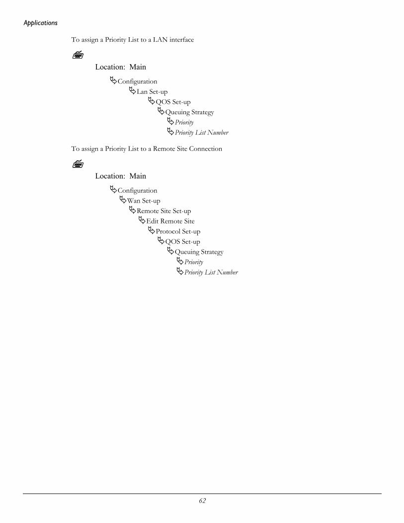
Applications
62
To assign a Priority List to a LAN interface
Location: Main
ConfigurationLan Set-up
QOS Set-upQueuing Strategy
PriorityPriority List Number
To assign a Priority List to a Remote Site Connection
Location: Main
ConfigurationWan Set-up
Remote Site Set-upEdit Remote Site
Protocol Set-upQOS Set-up
Queuing StrategyPriorityPriority List Number

Applications
63
Simple Network Time Protocol (SNTP)
The Simple Network Time Protocol (SNTP) feature on the Perle Routers support the clientside of the protocol as described in RFC 2030. The router will be able to obtain its timefrom a NTP or SNTP server and then can be synchronized amongst other network devices.Additionally, the router can also be configured to support various time variations featuressuch as local time zone and adjustments for daylight savings time.
When the Perle router has SNTP enabled it will periodically send NTP packets to theNTP/SNTP server which will respond with the network time. The router will synchronizeits internal clock with the response from the NTP/SNTP server. The method in which therouter sends or receives the NTP packets from the NTP/SNTP server is configurable inthree modes: unicast, multicast and anycast.
In unicast mode, the router will have to be configured with the IP Address of the NTPserver and will periodically send a request packet to the NTP server. The NTP server willthen respond directly to this request with the current time. The Perle router supports aprimary and a secondary IP Address for NTP servers.
In multicast mode, the router does not initiate the request packets but waits to receive theperiodic broadcasts from the NTP server with the current time. Once the router receives anNTP packet from the server, it will then synchronize its internal clock with the current time.
In anycast mode, the router will send out a request packet as a broadcast on the LAN to geta response from any NTP server. When the first response is received from an NTP server,the internal clock of the router is synchronized. The router will learn the IP Address of theNTP server that responded and then operate in unicast mode.
The Perle router supports time variation feature of local time zones and daylight savingstime regardless if the internal clock is synchronized with an NTP server. The local time zonefeature allows the router to offset the internal clock by a configurable time from the UTCtime. The configurable time zone off set can be specified in hours (0 to 23) and minutes (0to 59) and can also be specified by a specific name up to 4 characters.
Adjustments to the internal clock for daylight saving time (Summer-time) can be enabledand specified for one time within the year or recurring year after year. Configurationparameters allow the router to enable Summer-time each year by specifying the month,week, day and hour for the begin and end Summer-time.
To enable SNTP on the router and setup for unicast mode to directly obtain the time from aspecific NTP server implement the following steps.
Location:
ConfigurationApplication Set-up
SNTP Set-upSNTP Client
enableMode
unicastPrimary IP Address

Applications
64
IP Address (XXX.XXX.XXX.XXX)Secondary IP Address
IP Address (XXX.XXX.XXX.XXX)Version
3
The time zone and daylight savings time configuration is setup within the device setupmenu. To configure for Eastern Standard Time (EST) and have daylight saving timeimplemented for this year only, implement the following steps:
Location:
ConfigurationAccess Set-up
Device Set-upTime Zone Setup
Hours Offset5
Minutes Offset0
NameEST
Summer Time SetupSummer Time
enabledSummer Time Mode
dateSummer Time Start
YearMonthDateTime
Summer Time EndYearMonthDateTime
Offset 60

Introduction to Filtering
65
3 Introduction
to Filtering
The P1705 & P1730 provide programmable filtering which gives you the ability to controlunder what conditions Ethernet frames are forwarded from one network to another. Thereare many reasons why this might need to be accomplished, some of which are security,protocol discrimination, bandwidth conservation, and general restrictions.
Filtering may be accomplished by using two different methods. The first method is to filteror forward frames based solely on their source or destination MAC address. This methodof filtering is useful when bridging between LANs and for providing remote access securityin any type of network. The Ethernet MAC (Media Access Control) address is checkedagainst the addresses in the filtering list and the frame is filtered or forwarded accordingly.
The second method of filtering is pattern filtering where each frame is checked against afilter pattern. The filter pattern may be defined to perform a check of any portion of theEthernet frame. Separate filter patterns may be defined for bridged frames, IP routedframes, and IPX routed frames.
For more information on filtering, please refer to the Programmable Filtering section of theP1705 & P1730 Reference Manual located on the accompanying CD-ROM.
MAC Address Filtering
MAC address filtering is provided by three built-in functions.
The first function is “Filter if Source”; the second is “Filter if Destination.” The thirdfunction allows you to change the filter operation from “positive” to “negative.” Thepositive filter operation causes frames with the specified MAC addresses to be filtered. Thenegative filter operation causes frames with the specified MAC addresses to be forwarded.
You may easily prevent any station on one segment from accessing a specific resource onthe other segment; for this, “positive” filtering and the use of “Filter if Destination” wouldbe appropriate. If you want to disallow a specific station from accessing any service, “Filterif Source” could be used.
You may easily prevent stations on one segment from accessing all but a specific resourceon the other segment; for this, “negative” filtering and the use of “Forward if Destination”would be appropriate. If you want to disallow all but one specific station from accessing anyservice on the other segment, the use of “Forward if Source” could be used.
Introduction to Filtering
66
Pattern Filtering
Pattern filtering is provided in three separate sections: Bridge Pattern Filters, IP RouterPattern Filters, and IPX Router Pattern Filters. When the router is operating as an IP/IPXBridge/Router, each of the frames received is passed on to the appropriate internal sectionof the router. The IPX frames are passed on to the IPX router, the IP frames are passedon to the IP router, and all other frames are passed on to the bridge. Different patternfilters may be defined in each of these sections to provide very extensive pattern filtering onLAN traffic being sent to remote LANs.
Pattern filters are created by defining an offset value and a pattern match value. The offsetvalue determines the starting position for the pattern checking. An offset of 0 indicates thatthe pattern checking starts at the beginning of the data frame. An offset of 12 indicates thatthe pattern checking starts at the 12th octet of the data frame. When a data frame isexamined in its HEX format, an octet is a pair of HEX values with offset location 0 startingat the beginning of the frame. Please refer to Appendix C - Octet Locations on Ethernet Framesfor more information on octet locations in data frames.
The pattern match value is defined as a HEX string that is used to match against the dataframe. If the HEX data at the appropriate offset location in the data frame matches theHEX string of the filter pattern, there is a positive filter match. The data frame will befiltered according to the filter operators being used in the filter pattern.
The following operators are used in creating Pattern filters.
- offset Used in pattern filters to determine the starting position to start the patternchecking.
Example: 12-80 This filter pattern will match if the packetinformation starting at the 12th octet equals the 80of the filter pattern.
| OR Used in combination filters when one or the other conditions must be met.
Example: 10-20|12-80 This filter pattern will match if the packetinformation starting at the 10th octet equals the 20of the filter pattern or if the packet informationstarting at the 12th octet equals the 80 of the filterpattern.
& AND Used in combination filters when one and the other conditions must bemet.
Example: 10-20&12-80 This filter pattern will match if the packetinformation starting at the 10th octet equals the 20of the filter pattern and the packet informationstarting at the 12th octet equals the 80 of the filterpattern.
~ NOT Used in pattern filters to indicate that all packets not matching the definedpattern will be filtered.

Introduction to Filtering
67
Example: ~12-80 This filter pattern will match if the packetinformation starting at the 12th octet does notequal the 80 of the filter pattern.
( ) brackets Used in pattern filters to separate portions of filter patterns for specificoperators.
Example: 12-80&(14-24|14-32) This filter pattern will be checked in twooperations. First the section in brackets will bechecked and then the results of the first check willbe used in the second check using the first portionof the filter pattern. If the packet informationstarting at the 14th octet equals 24 or 32, and theinformation at the 12th octet equals 80, the filterpattern will match.
Popular Filters
Shown here are some of the more commonly used pattern filters.
Bridge
Bridge pattern filters are applied to Ethernet frames that are bridged only. When the routeris operating as a router, all routed frames will be unaffected by the bridge pattern filters.
IP & Related TrafficIP & Related Traffic
Forward only ~(12-0800|12-0806)Filter (12-0800|12-0806)
Novell IPX FramesNovell IPX Frames
EthernetII (12-8137)802.3 RAW (14-FFFF)
802.2 (14-E0E0)802.2 LLC (14-AAAA&20-8137)
NetBIOS &NetBEUI (Windows For Workgroups)NetBIOS & NetBEUI (Windows For Workgroups)
Filter (14-F0F0)Forward only ~(14-F0F0)

Introduction to Filtering
68
BanyanBanyan
(12-0BAD)(12-80C4)(12-80C5)
IP Router
IP router pattern filters are applied to IP Ethernet frames that are being routed. When therouter is operating as an IP router, all IP routed frames will be checked against the definedIP router pattern filters. IP routed frames are unaffected by the bridge pattern filters andthe IPX router pattern filters.
NetBIOS over TCPNetBIOS over TCP
NETBIOS Name Service (22-0089)NETBIOS Datagram Service (22-008A)NETBIOS Session Service (22-008B)
Note: Uses the TCP Destination Port location
Other interesting TCP PortsOther interesting TCP Ports
Decimal Hex Usage
21 15 FTP23 17 Telnet25 19 SMTP69 45 TFTP109 6D POP2110 6E POP3

69
Appendix AMenu Trees
The menu trees on the following pages are a graphical representation of the hierarchy of the built-inmenu system of the P1705 & P1730. Each of the menus are shown with the options of the menusbeing displayed below the specific menu name.
Each of the menu options shown in each of the menu trees is explained in the accompanying P1705& P1730 Menus Manual located on the accompanying CD-ROM.
Menu names are displayed in boxes. The numbers on the left side of the boxes indicate the menuoption from the parent menu that this menu corresponds to. All menu options are listed withnumbers indicating their actual position within the menu system.
Menu options contained within a grayed box are ISDN options. Menu options contained within ablack box are Frame Relay options.

1 Configuration
1. Terminal2. Show3. Add4. Remove
1. Terminal Set-Up menu2. Device Set-Up menu3. Telnet Set-Up menu4. Load FLASH Set-Up menu5. Console6. Hardware Status7. TFTP access
Access Set-Up1]1]1] 2]2] 3] 4] 5]
1. Password2. Device Name3. Show Time4. Set Time5. Time Zone6. Summer Time
1. Telnet access2. Telnet3. Telnet port4. Show Names5. Add Name6. Remove Name
1. Console (ZMODEM)2. Network (TFTP)
1. Dump2. Restore
Terminal Set-Up Device Set-Up Telnet Set-Up
ISDN Options
Frame Relay Options
1730 only
Load FLASH Set-Up Console
1. IP routing menu2. NAT Advanced menu3. IP enabled4. NAT enabled5. Link IP address6. Peer IP address7. Private Route/Negotiate address8. VJ compression
1. IPX enabled2. Link IPX type3. IPX net4 Local IPX node5. Peer IPX node6. Static routes only7. IPX DMR enabled8. Force RIP update
1. Compression2. Extended sequence
1. Edit Remote Site menu
1. Advanced PPP Set-Up menu
1. Edit IP address entry2. IP address connect3. Show IP address entries4. Remove IP address entry5. Remote site summary
IP Address Connect
WAN Set-Up
Advanced PPP Set-Up
IP Parameters
IPX Parameters
CCP Parameters
1]
7]
Remote Site Set-Up
Group Set-Up
PPP Set-Up
2. Remote site summary3. Display learned summary3. Call summary4. Remove remote site5. Manual call6. Force disconnect
2. Restart Timer3. Configure Count4. Failure Count5. Terminate Count
1. ACFC2. PFC3. Echo monitoring4. Quality protocol5. Quality interval6. MP encapsulation7. MP sequencing8. MP discriminator9. MP minimum
4]
2]
6]
3]
2]
3]
4]
1. Bridge set-up menu2. IP set-up menu3. IPX set-up menu4. LAN interface type
LAN Set-Up2]
Continued onnext page
MAIN
1. State2. Path cost3. Priority
Bridge-STP Set-Up
1]
1. Usage limit2. Call limit3. Restart time
1. Activation intervals2. Display schedule3. Display time
2]
3]
1]
1. IP set-up2. LAN-NAT set-up3. IP address4. Routing protcol5. RIP mode6. Route cost
Secondary
LAN IP Set-Up2]
1. Connection set-up menu2. Activation menu3. Protocol set-up menu4. Security parameters menu5. Remote site alias6. Connection7. Primary connection8. Secondary connection9. Remote site type
Edit Remote Site1]
1. Bridge parameters menu2. IP parameters menu3. IPX parameters menu4. CCP parameters menu5. CMCP parameters menu6. BACP set-up menu7. Multilink8. QOS Set-Up9. PPPoE
Protocol Set-Up
1. Incoming PAP password2. Incoming CHAP secret3. Outgoing user name4. Outgoing PAP password5. Outgoing CHAP secret
Security Parameters
3]
4]
2. Bridge enabled3. Tinygram4. FCS preservation
Bridge Parameters1]
1. STP parameters menu 1. State2. Path cost3. Priority
1. Callback timer2. Redial timer3. Redial count
STP Parameters1]
1. Routing protocol2. RIP mode3. Triggered RIP4. Auto Default Route5. Link cost
1. Translation type2. Show address pool3. Dynamic IP pool4. Add static entry5. Remove static entry6. TCP mss7. TCP mss value
1. Translation type2. Show address pool3. Dynamic IP pool4. Add static entry5. Remove static entry6. NAT enable
IP Routing
NAT advanced
LAN-NAT set-up
1]
2]
2]
3. CMCP enabled4. Bridge traffic5. Disc after last6. Suspension timeout
CMCP Parameters5]
1. IP spoofing menu2. IPX spoofing menu
1. TCP idle2. TCP interval3. TCP retries4. TCP aging
IP Spoofing1]
1. IPX type202. IPX broadcast3. IPX idle4. IPX interval5. IPX retries6. IPX aging
IPX Spoofing2]
1. Default parameters menu2. Security level3. Request security4. CHAP challenges5. Caller ID security
1. Outgoing user name2. Outgoing PAP password3. Outgoing CHAP secret
Security Set-Up Default Parameters5]
Connection Set-Up
2. Primary link 3. Secondary link4. Auto-call
1]
1. Up threshold2. Up stability timer3. Down threshold4. Down stability timer
2]Activation
Threshold
1. Schedule2. Usage set-up3. Threshold set-up4. Inactivity timer5. Recovery timer
1. Advanced settings menu2. ISDN number3. Alternate ISDN #4. Group5. Wildcard6. Call you7. Call me8. Callback
ISDN call Set-UpAdvanced settings
Usage Set-Up
Schedule
1]1]
1. Force 56k2. Hunt Group #3. Add link4. Show Groups
1. Switch type 1]1. Edit Secondary2. Show Secondary Entry3. Remove Secondary Entry 1. Secondary IP
2. Mask Size3. Subnet Mask4. Routing Protocol5. RIP mode6. Private Route7. Route Cost
Secondary IP Set-UpEdit Secondary
1]
Menu Tree
BACP Set-Up6]
1. BACP2. Call mode3. Request number
QOS Set-Up8]
1. Queuing Strategy
8. Force disconnect9. Link summary
software release: 51P6.02.xx52P6.06.xxsoftware release:
1. Ethernet-II frames2. RAW 802.3 frames3. IEEE 802.2 frames4. 802.2 SNAP frames5. Auto Learn6. Help
LAN IPX Set-Up3]
1. Queuing StrategyQOS Set-Up
ISDN Set-Up
Link Set-Up1. Physical link type2. Link operation3. Logical ISDN type4. ISDN set-up menu5. Group4. Phantom Power detect5. Link B channel
1. Auto learning 2. LMI type3. Polling interval4. Enquiry interval5. Error threshold6. Monitored events
3]4]
4]
1. Dial prefix2. Phantom power detect3. Force 56k4. Directory number5. SPID
T1/E1 Set-Up
Slot/Channel Set-Up
1. Link mode2. LBO3. T1/E1 framing4. Channel rate/Speed5. E1 CRC46. Slot/Channel Set-Up7. Line encoding8. Alarm generation9. T1.403 PRM
1. Idle code2. Number3. Start4. Speed5. E1 timeslot 166. Status
5]
6]

Continued fromprevious page
1. Destination2. Status3. Remote site2. Next hop3. Type4. Cost5. Private6. Add/Remove
8. Status7. Network mask
Edit Static Route1. IP Routes menu 1. Edit Static Route2. Default Gateway3. Show all Routes4. Show Static Routes5. Clear Static Routes
2. ARP Set-up menu3. IP routing4. IP forwarding5. ARP proxy
IP Routing Set-UpIP Routes
1]1]
6]
1]
1. Edit Route 1. Edit Service1. Status2. Network3. Interface4. Hops5. Ticks
Edit Route1]
1. Status2. Server Name3. Service Type4. Interface5. Network6. Node7. Socket8. Hops
Edit Service1]
2. Convert Route3. Show Static Routes4. Clear Static Routes
2. Convert Service3. Show Static Services4. Clear Static Services
Static Routes Static Services2]1. Static Routes menu
2. Static Services menu3. IPX Routing4. IPX Forwarding5. Local Networks6. Show Routes7. Show Services8. Help
IPX Routing Set-Up7]
1. STP State2. Bridge Priority3. Forwarding Delay4. Message Age Timer5. Hello Time6. Show Bridge7. Show Ports
1. Spanning Tree menu 2. Bridge Forwarding3. Bridge Aging Timer4. Show Bridging Table5. Show Permanent Table6. Clear Bridging Table
Bridging Set-Up Spanning Tree1]5]
1. Priority Queuing
QOS Set-Up9]
1. Edit List2. Show Priority List3. Remove Priority List4. Show Statistics5. Clear Statistics
Priority Queuing1]
1. Edit Items2. Show Items3. Remove Items4. Default Priority5. Queue Limit Setup
Edit Priority List1] 1. Priority
2. Selection3. Protocol Parameter
Edit Item1]
1. High2. Medium3. Normal4. Low
Queue Limit Set-Up5]
1. Show Alias2. Add Alias3. Remove Alias4. Show Pattern5. Add Pattern6. Remove Pattern7. Help
1. Show Alias2. Add Alias3. Remove Alias4. Show Pattern5. Add Pattern6. Remove Pattern7. Help
1. Show Alias2. Add Alias3. Remove Alias4. Show Pattern5. Add Pattern6. Remove Pattern7. Help
IP Router PatternFilters
Bridge PatternFilters
IPX Router PatternFilters
MAC Address Filters
Filter Set-Up
1. MAC Address Filters2. Bridge Pattern Filters3. IP Router Pattern Filters4. IPX Router Pattern Filters
2. Filter Operation3. Broadcast Address4. Show Bridging Table5. Show Permanent Table6. Clear Bridging Table
1. Edit MAC Address Filter
1. Status2. Location3. Filter If Source4. Filter If Destination5. Permanent6. Remove
Edit MACAddress Filter
1]
1]
3]2] 4]8]
1. ARP aging timer2. ARP retry timer3. Add4. Remove5. Show ARP table
ARP Set-Up2]
1. Designated servers menu2. Edit firewall entry menu
Clear statisticsShow firewall entriesRemove entry
3.Firewall4. Firewall statistics5. 6. 7.
1. LAN firewall setup menu2. WAN firewall setup menu3. Block src IP spoofing
Firewall Set-Up
LAN / WAN Firewall Set-Up
3]
1,2]
1. E-mail (SMTP) server2. POP 2/3 server3. FTP server4. WWW (HTTP) server5. Telnet server6. Local DNS7. Remote DNS8. Secondary local DNS9. Secondary remote DNS
Designated Servers1]
1. Dest IP address2. Destination mask3. Source IP address4. Source mask5. Protocol type6. Source port7. Destination port8. Description9. Entry direction
Edit Firewall Entry2]
NAT Exports Syslog4] 5]
1. Edit Services2. Router port3. Default export4. Show services5. Clear services
1. Syslog2. Syslog IP3. Events4. Security5. Activation6. Firewall
1. Other Services menu2. E-mail 3. POP 2/3 4. FTP5. WWW (HTTP)6. Telnet7. DNS
Edit Services
Other Services
1]
1]
1.Telnet2. TFTP3. SNMP
1.NAT port2. Status3. Host IP address4. Host port5. Description6. Remove
Router Port2]
Application Set-Up4]
1. Server IP pool address menu2.DNS setup menu3. NetBIOS setup menu4. DHCP services5. Relay destination6. ICMP echo verification7. Lease period8. Default Gateways
DHCP Set-Up2]
1. IP address pool2. Show address pool3. Add static address4. Remove static address
Server IP address pool1]
1. Send NetBIOS node type2. Send NetBIOS scope3. Send NetBIOS name srv4. NetBIOS node type5. NetBIOS scope Id6. NetBIOS name server
NetBIOS Setup3]
1. Primary DNS2. Secondary DNS3. Domain name
DNS Set-Up2]
1. Write Access2. Show Addresses3. Add Address4. Remove Address
Edit Community1]
SNMP Set-Up1. Edit Community menu 2. Message Size3. Show Communities4. Remove Community
1]
6 Help
3
41. Acknowledge alarm2. Show events3. Clear events4. Show security log5. Clear security log6. Show resumption log7. Clear resumption log
Network Events
5 Logout
21. Statistics set-up menu
2. Remote site information menu 3. LAN statistics menu 4. Link stats 5. Link summary 6. Interface stats 7. Interface status 8. Clear link & interface stats
1] 2] 3]
1. Extended Statistics2. Interval3. Clear All Statistics
Statistics1. Bridged traffic2. IP traffic3. IPX traffic4. Total LAN traffic5. LAN error6. Clear LAN statistics7. Clear LAN errors
Statistics Set-Up LAN Statistics
1.Common protocol stats2. PPP statistics
4. Status5. Usage information6. Clear remote site stats
3. Frame relay statistics
Remote SiteInformation
software release: 51P6.02.xx 52P6.06.xxsoftware release:
Menu Tree
4]
1. Soft Reset2. Full Reset3. Heartbeat4. WAN trace5. WAN loopback
1. Trace link2. Real Time3. Capture4. End5. Data display6. Time
Diagnostics WAN Trace 2]
3]
5]
1. Link operation2. Data test2. Test pattern set-up menu3. T1/E1 loopback menu3. CSU/DSU self test4. CSU/DSU digital loopback5. CSU/DSU remote loopback6. Help
WAN Loopback1. Pattern2. Start Xmt
1. Loopback type2. Loopback node3. Loopback delay4. Start/Stop loopback
Test Pattern Set-Up
T1/E1 Loopback
1. SNMP set-up menu2. DHCP set-up menu3. Firewall set-up menu4. NAT exports5. Syslog6. Time to live7. Traceroute8. Ping9. SNTP Set-up menu
SNTPg 9)
1. SNTP Client2. Mode3. Primary Server IP 4. Secondary Server5. Version

72
Appendix BOctet Locations on
Ethernet Frames
This appendix provides octet locations for the various portions of three of the commonEthernet frames. When creating pattern filters these diagrams will assist in the correctdefinition of the patterns. The offset numbers are indicated by the numbers above theframe representations.
Note the differences in the TCP/IP and Novell frames when bridging and when routing.When routing, the TCP/IP and Novell frames are examined after the Level 2 Ethernetportion of the frame has been stripped from the whole data frame. This means that theoffset numbers now start from 0 at the beginning of the routed frame and not the bridgedframe.
Some of the common Ethernet type codes are also shown here. The Ethernet type codesare located at offset 12 of the bridged Ethernet frame.
Octet Locations on a Bridged TCP/IP Frame

Configuration Pages
73
Octet Locations on a Bridged Novell Netware Frame
ETHERNET Type CodesType Code Description
0800 DOD IP0801 X.75 Internet0804 Chaosnet0805 X.25 Level 30806 ARP0807 XNS Compatibility6001 DEC MOP Dump/Load6002 DEC MOP Remote Console6003 DEC DECNET Phase IV Route6004 DEC LAT6005 DEC Diagnostic Protocol6006 DEC Customer Protocol6007 DEC LAVC, SCA8035 Reverse ARP803D DEC Ethernet Encryption803F DEC LAN Traffic Monitor809B Appletalk80D5 IBM SNA Service on Ether80F3 AppleTalk AARP (Kinetics)
8137-8138 Novell, Inc.814C SNMP

Octet Locations
74
Octet Locations on an IP Routed TCP/IP Frame
Octet Locations on an IPX Routed Novell NetwareFrame
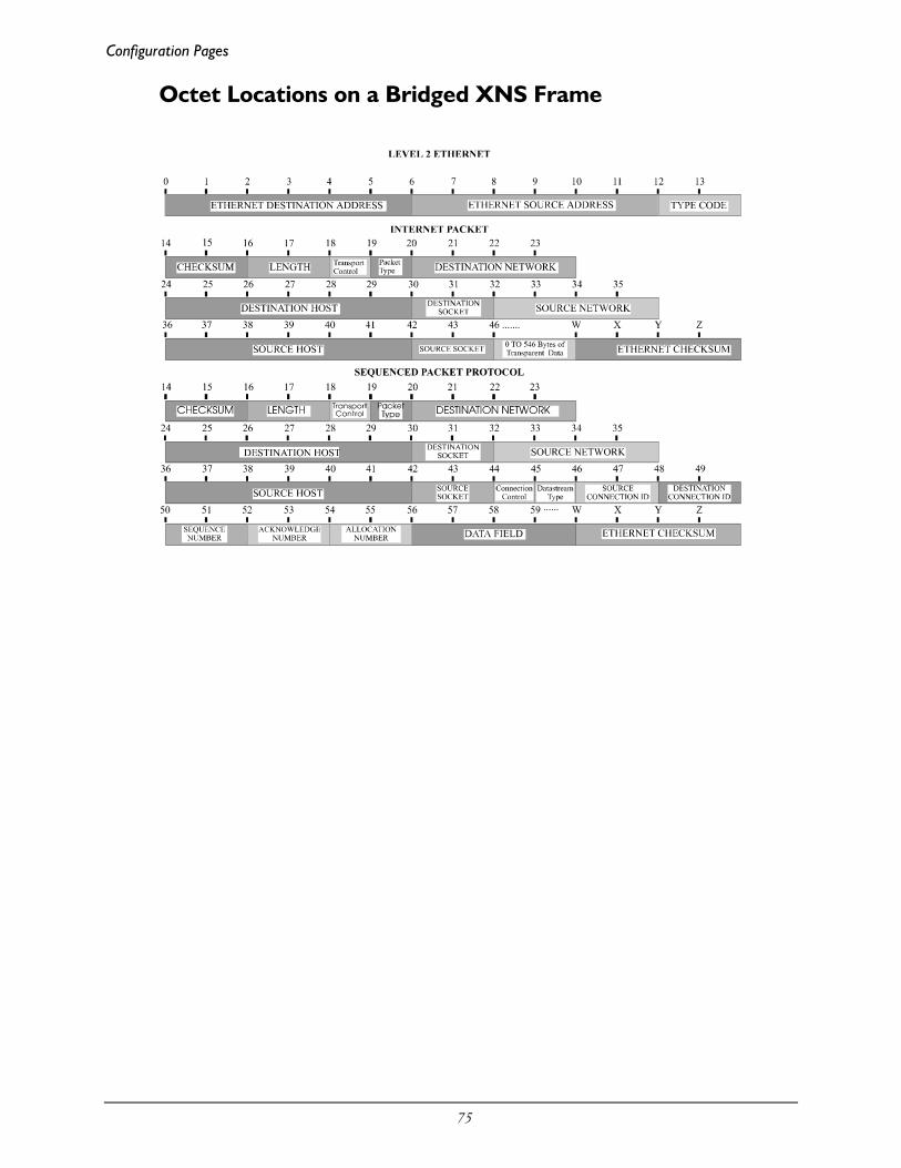
Configuration Pages
75
Octet Locations on a Bridged XNS Frame

76
Appendix CServicing Information
Opening of the case and changing of modules is only tobe performed by qualified service personnel.
WARNING !Always disconnect the power cord from the rear panel of the bridge/router.
The bridge/router case does not need to be opened to change LAN or WAN interfacemodules.
Opening the case
1) Remove power from the bridge/router and remove the other cabling.
2) Turn the bridge/router over and place it on a flat, cushioned surface.
3) Remove the six Phillips head screws that fasten the case together (4 across the frontand 1 on each rear side).
4) Hold the two halves of the case together and turn the bridge/router right-side up.
5) Lift off the top half of the case. The LEDs in the front panel of the bridge/router areconnected to the main board by a short ribbon cable. When lifting the top half of thecase off, the lid should be lifted from the back and hinged at the front. The lid willthen fold completely over and lie top down.

Servicing Information
77
Identifying the Internal Components
The major components of concern are shown in the following illustration.
Link 2 Interface Module
(ISDN BRI, DSU,G.703, RS232, V.35,
RS422 or V.11)
Primary LAN & Console
Interface Module
Link 1
LAN 2or
Module
(ISDN BRI, DSU,G.703, RS232, V.35,
RS422 or V.11)
Interface
FlashMemory
Figure C-1 Top Internal View of the P1705 & P1730 Ethernet Bridge/Router

Servicing Information
78
To Clear a “Lost” Password
1) Remove power from the bridge/router.
2) Remove the screw securing the LAN / Console module to the rear of thebridge/router. Be sure to grip the module only by the flange at the bottom of themetal panel.
3) Unplug the LAN / Console module approximately 1/2 inch from thebridge/router. Be sure to grip the module only by the flange at the bottom of themetal panel. The module only needs to be removed slightly to disconnect themodule from the internal main board.
WARNING:
Because of the close proximity of the AC power from the powercoupler, do not insert anything into the LAN / Console opening while
the bridge/router is powered up.
4) Reattach the power to the bridge/router and wait for the power-up diagnostics tofinish. The Power LED will turn green.
5) Remove power from the bridge/router.
6) Re-install the LAN / Console module and secure it with the screw.
7) Power up the bridge/router.
8) Log into the bridge/router using the default password “BRIDGE” and change thepassword as desired.
Changing LAN or WAN Interfaces
1) Remove power from the bridge/router.
2) Remove the screw securing the interface module to the rear of the bridge/router.
3) Remove the interface module from the bridge/router. Be sure to grip the moduleonly by the flange at the bottom of the metal panel.
4) Install the new interface module and secure it with the screw.
5) Power up the bridge/router.
Important: there must be a module in slot 1 (left side module position when viewed fromthe rear of the unit) before a module in slot 2 (center position) will operate.
For P1730 models, if a LAN 2 module is installed it must go in slot 1. Note inaddition that installing a LAN 2 module will clear the IP address of LAN 1. Afterinstalling a LAN 2 module, the IP address for both LANs must be entered.
Selecting MDI or MDI-X LAN Interface
For most LANs, where a number of devices are connected via a hub, this router will beconnected via the LAN cable to the MDI port. However, in locations where a singleworkstation is to be connector to the router, the cable from the workstation should beplugged into the MDI-X port. This eliminates the need for a hub at a remote site that hasonly one LAN device.

Servicing Information
79
Installing the ISDN Link Modules
If there is an ISDN module plus another type of WAN interface module or if thereis a single ISDN module, the ISDN U or S/T Module must only be installed in theSlot 1 position. The slot 2 position may contain another type of WAN module ormay be unused and covered with a blank panel. For P1730 models, if there is asecond LAN module in this unit, it must go in the Slot 1 position and the ISDNmodule in Slot 2.
Note: the older double width type ISDN module will not fit in this device.
CONSOLE
Slot1 Slot 2 LAN/Console module
Remove these screwsto remove the modules.
LINE
ISDN-U
10/100 BT LAN
MDI-X MDI
Figure C-2 Rear View with the ISDN U Module Installed
Processor settings for the ISDN Link Modules
ISDN S/T or U modules have jumper straps to set the module for the CPU used on the mainboard. On an S/T interface, these are labeled W1 and W2; on a U interface, the pins are labeledJ1. When installing an ISDN module, check the jumpers to be certain that they are configured tooperate with the 360 series CPU by having both straps across pins W1 and W2 (S/T module) oracross pins 1-3 and 2-4 at J1 (U module), as illustrated in the figure below.
Figure C-4 ISDN Module processor setting jumpers
JUMPERS

Servicing Information
80
Changing the Termination Straps on the ISDN S/TInterface
The ISDN S/T link interface module has two configurable straps that control whether theISDN LINE is set to terminated or unterminated.
Jumper straps W5 and W6 are factory installed to configure the module as TERMINATED.The TERMINATED position is used when the bridge/router is the only ISDN deviceconnected to the ISDN circuit.
Removing the W5 and W6 straps sets the module to UNTERMINATED. This allows thisbridge/router to be part of a daisy-chain connection to the ISDN circuit by using the ISDNAUX connector.
Figure C-5 ISDN S/T Module Termination setting jumpers
Connecting to the ISDN-U Link Module
The connection to the central office is made with the RJ45 connector on the panelof the U Module. Pins 4 and 5 are used for the connection. These pins are polarityinsensitive.
The Ferrite module included with the ISDN U Module must be installed on the cable that isconnected to the ISDN U Module. The Ferrite module must be installed approximately twoinches from the RJ45 connector at the bridge/router end of the cable. The cable must passthrough the Ferrite module twice with a Single loop around the Ferrite module.
Figure C-6 Ferrite Module Installed on the Cable.

Servicing Information
81
Performing a Software Upgrade
1) Execute the Network (TFTP) command from the Load FLASH Set-Upmenu.
2) Enter “none” to connect locally or enter the remote site ID number or aliasto connect to a remote site.
3) Start the TFTP application to be used for transfers to the router.(The IP address of the router may be found in the Internet Set-Up menu.).
4) Put the file “###.all” to the router from the Operational Code directory onthe CD-ROM.
(Any router not in Network Load BOOT mode will respond with an accessviolation error.)
5) The router will verify the file “###.all” in memory, program and verify theFLASH, clear the configuration to default values (except: IP Address, IPRouting state, IP Forwarding state, WAN Environment, Link 1 & 2 State,the Switch Type, Directory Numbers, SPIDs, Password and connectiondata for the remote site, if applicable), and then reset. After the reset, therouter will operate normally using the newly upgraded software. In someupgrade situations the Directory Numbers and SPIDs may be corruptedafter the upgrade and will need to be re-entered.
- The router may take up to two (2) minutes to program and verify theFLASH. The console will not respond during this time.
To check on the router’s current state during this process, get the file“status.txt” from the router. This file will report the router’s state: both themode and version if no errors have occurred, or an error message.
On the rare occasion that during the programming of the FLASH somethinghappens to the bridge/router (power hit or hardware reset), causing the FLASHto become corrupted, the bridge/router will restart in ZMODEM receive modeonly. If the bridge/router does not start in ZMODEM receive mode: power downthe bridge/router, remove the WAN module(s) and, if present, the second LANmodule, power up the bridge/router. The bridge/router should now restart andbe in ZMODEM receive mode. Once the file transfer is complete, the router willagain come up in ZMODEM receive mode. Power down the unit and replace theinterface modules.

Servicing Information
82
In the following diagram of a cluster of routers, when upgrading the three routersin the diagram, the upgrade order should be Router C, then Router B, and finallyRouter A.
A TFTP software load to router C would be performed as follows:
- Using TFTP, get config.txt from each router and save.
- Telnet to Router C. Enter the ID or alias of Router B in the Network (TFTP)option to put Router C in Network Load mode. When Router C restarts inNetwork Load mode, the connection to “Router B” will be re-establishedonly if autocall is enabled on router B.
- The TFTP transfer of the upgrade code may now be performed from the PCto Router C. Once Router C has completed programming the flash and hasrestarted in operational mode, the connection to Router B will be re-established only if autocall is enabled on router B.
Once router C is operating with the new software, the PC may be used to reload theconfig.txt file back to Router C.
Repeat for Router B, then again for Router A. Perform the Router B upgrade using theID or alias of Router A. Router A upgrades would not require a remote site ID as thePC used for TFTP transfers is located on the same LAN as Router A.
Router A
PC used forTFTP transfers
Router B
Router C

Servicing Information
83
Appendix DInterface Pinouts
Pinout InformationEach link interface available is described with detailed information on pin designation. Standard interfacecables will provide correct connections to modems, datasets, or DSU/CSUs.
When connecting two bridge/routers back-to-back without modems, a null-modem cable isrequired to crossover the pins on the links. Crossing over the pins allows two bridge/routersboth configured as DTE interfaces to be connected together. With this configuration, bothbridge/routers will provide clocking for the links, and each bridge/router must have a link speeddefined.
Link Clocking InformationAll of the link interfaces on the router act as DTE devices, this means that they may be directlyconnected to DCE devices (modems, etc.) with the DCE devices providing the clocking for thelink. The link speed is controlled by the DCE device. Setting the link speed on the router willnot result in a speed change on the link.
Some DCE devices allow the DTE devices connected to them to supply a clock signal which isthen routed back to the transmit clock pins on the DCE interface. This clock is then received bythe router link interface. By using this method, the router may be in control of the link speed.The link speed may also be controlled by the router when a null-modem cable is used toconnect two routers in a back-to-back configuration.
Changing the link speed within the menu system of the router changes the clock output speedthat is generated on the DTE Terminal Timing pins (external clocking pins) on the linkinterfaces.
ATL-CSU/DSU Link Module InformationThe P1705 & P1730 are currently produced with LXT CSU/DSU interface modules; however,the earlier model ATL CSU/DSU module is still compatible with the router and may be usedwith it. Note that ATL master mode signaling is not compatible with the current standard 64Kmaster mode signaling; therefore, for back to back connections, an ATL unit will only operate at64K when connected to another ATL unit. If one interface is an ATL unit and the other is not,back to back operation must be set to 56K.
The ATL-CSU/DSU link module is normally configured to receive clock from the connectednetwork. When two ATL-CSU/DSU link modules are to be used on a leased line in a back-to-back set-up, one of the modules must provide the clock.

These modules may have either the UP/DOWN switch type or the ON/OFF slide switch type.Each type is illustrated below.
CSU/DSULINE
1 2 3 4
Switches
updown
Figure D-1 Rear View of ATL-CSU/DSU Link Module with UP/DOWN Switches
Figure D-2 View of ATL-CSU/DSU Link Module with Sliding ON/OFF Switches
When connecting two bridge/routers back-to-back with CSU/DSU link modules, a null-modemcable is required to crossover the pins on the links. Crossing over the pins allows two bridge/routersboth configured as DTE interfaces to be connected together.
Switch number 1 determines whether the ATL-CSU/DSU link module will generate clocks orreceive clocks. When switch 1 is down (on), the normal position, the module receives clock signalsfrom the connected network. When switch 1 is up (up), the module will generate clocks. When apair of routers are connected back-to-back with CSU/DSU link modules one module must be set togenerate clocks and one module must be set to receive clocks.
On 64 Kbps units only, switch number 3 determines the mode of the ATL-CSU/DSU. Whenswitch 3 is down (on), the ATL-CSU/DSU is in DDS (Digital Data Service) mode for normalconnection to the 64 Kbps digital service. When switch 3 is up (off), the ATL-CSU/DSU is inLDM (Limited Distance Modem) mode for back-to-back connection with a null-modem cable.
On 56 Kbps units, the position of switch 3 is not a factor for back-to-back connection with a null-modem cable. Switch 1 must still be set as noted above.
A DSU/CSU crossover cable would be constructed as follows: 1 --> 72 --> 87 --> 18 --> 2
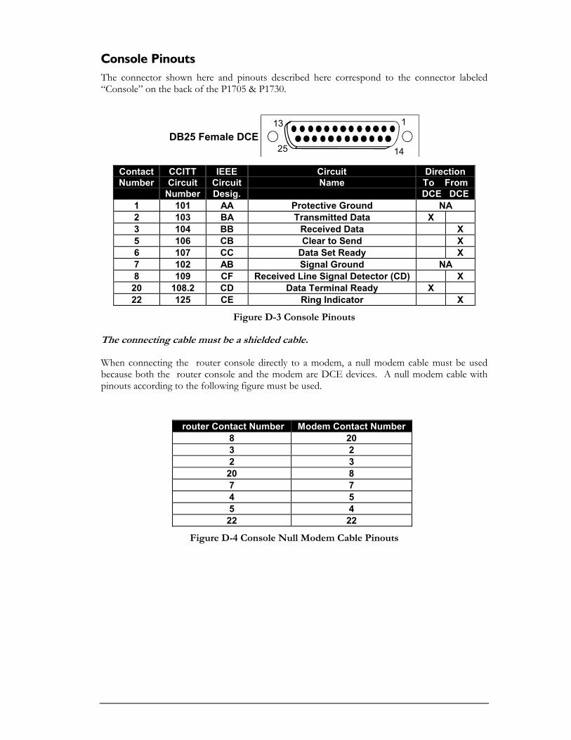
Console PinoutsThe connector shown here and pinouts described here correspond to the connector labeled“Console” on the back of the P1705 & P1730.
DB25 Female DCE 13 1
25 14
ContactNumber
CCITTCircuit
Number
IEEECircuitDesig.
CircuitName
DirectionTo FromDCE DCE
1 101 AA Protective Ground NA2 103 BA Transmitted Data X3 104 BB Received Data X5 106 CB Clear to Send X6 107 CC Data Set Ready X7 102 AB Signal Ground NA8 109 CF Received Line Signal Detector (CD) X20 108.2 CD Data Terminal Ready X22 125 CE Ring Indicator X
Figure D-3 Console Pinouts
The connecting cable must be a shielded cable.
When connecting the router console directly to a modem, a null modem cable must be usedbecause both the router console and the modem are DCE devices. A null modem cable withpinouts according to the following figure must be used.
router Contact Number Modem Contact Number8 203 22 320 87 74 55 422 22
Figure D-4 Console Null Modem Cable Pinouts

V.24 & RS232C Link Pinouts
The connector shown here and pinouts described here correspond to the connector labeled“RS232 / V.24” on the back of the P1705 & P1730.
DB25 Female DTE 13 1
25 14
ContactNumber
CCITTCircuit
Number
Circuit CircuitName
DirectionTo FromDCE DCE
1 101 AA Protective Ground NA2 103 BA Transmitted Data X3 104 BB Received Data X4 105 CA Request to Send X5 ----------6 107 CC Data Set Ready X7 102 AB Signal Ground NA8 109 CF Received Line Signal Detector (CD) X9 ----------10 ----------11 ----------12 ----------13 ----------14 ----------15 114 DB Transmit Signal Element Timing (DCE
Source)X
16 ----------17 115 DD Receive Signal Element Timing (DCE Source) X18 141 Local Loopback X19 ----------20 108.2 CD Data Terminal Ready X21 ----------22 125 CE Ring Indicator X23 ----------24 113 DA Transmit Signal Element Timing (DTE Source) X25 ----------
Figure D-5 RS232 Link Pinouts
The connecting cable must be a shielded cable.
NOTE For U.K. Approval:
The connecting cable may be any length between 0 and 5M. Each end must be terminated in amale 25 pin X.21 bis connector as defined in ISO-2110 1989.

V.11/X.21 Link Pinouts
The connector shown here and pinouts described here correspond to the connector labeled“V.11/x.21” on the back of the P1705 & P1730.
DB15 Female DTE 18
915
ContactNumber
X.21Circuits
ReferenceCircuitName
DirectionTo FromDCE DCE
1 Protective Ground NA2 T (A) Transmitted Data (A) X3 C (A) Control (A) X4 R (A) Received Data (A) X5 I (A) Indication (A) X6 S (A) Signal Element Timing (A) X7 ----------8 Ground Signal Ground NA9 T (B) Transmitted Data (B) X10 C (B) Control (B) X11 R (B) Received Data (B) X12 I (B) Indication (B) X13 S (B) Signal Element Timing (B) X14 ----------15 ----------
Figure D-6 V.11/x.21 Link Pinouts
The connecting cable must be a shielded cable.
Circuits which are paired (contain an (A) and (B) reference) should be connected totwisted pairs within the connecting cable.
NOTE For U.K. Approval:
The connecting cable may be any length between 0 and 5M. Each end must be terminated in amale 15 pin X.21 connector as defined in ISO-4903 1989, but one end of the cable must haveUNC-4-40 screws and the other end must have M3 screws.
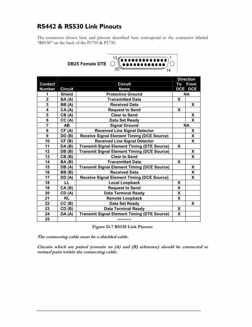
RS442 & RS530 Link Pinouts
The connector shown here and pinouts described here correspond to the connector labeled“RS530” on the back of the P1705 & P1730.
DB25 Female DTE 13 1
25 14
ContactNumber Circuit
CircuitName
DirectionTo FromDCE DCE
1 Shield Protective Ground NA2 BA (A) Transmitted Data X3 BB (A) Received Data X4 CA (A) Request to Send X5 CB (A) Clear to Send X6 CC (A) Data Set Ready X7 AB Signal Ground NA8 CF (A) Received Line Signal Detector X9 DD (B) Receive Signal Element Timing (DCE Source) X10 CF (B) Received Line Signal Detector X11 DA (B) Transmit Signal Element Timing (DTE Source) X12 DB (B) Transmit Signal Element Timing (DCE Source) X13 CB (B) Clear to Send X14 BA (B) Transmitted Data X15 DB (A) Transmit Signal Element Timing (DCE Source) X16 BB (B) Received Data X17 DD (A) Receive Signal Element Timing (DCE Source) X18 LL Local Loopback X19 CA (B) Request to Send X20 CD (A) Data Terminal Ready X21 RL Remote Loopback X22 CC (B) Data Set Ready X23 CD (B) Data Terminal Ready X24 DA (A) Transmit Signal Element Timing (DTE Source) X25 ----------
Figure D-7 RS530 Link Pinouts
The connecting cable must be a shielded cable.
Circuits which are paired (contain an (A) and (B) reference) should be connected totwisted pairs within the connecting cable.

V.35 Link Pinouts
The connector pinouts described here correspond to the connector labeled “V.35” on theback of the P1705 & P1730.
13 1
25 14
DB25ContactNumber
M.34ContactNumber
CircuitName
DirectionTo FromDCE DCE
1 A Protective Ground NA2 ----------3 ----------4 C Request to Send X5 ----------6 E Data Set Ready X7 B Signal Ground NA8 F Data Channel Received Line Signal Detector X9 P Transmitted Data (A) X10 S Transmitted Data (B) X11 R Received Data (A) X12 T Received Data (B) X13 ----------14 V Receiver Signal Element Timing (A) X15 ----------16 X Receiver Signal Element Timing (B) X17 ----------18 U Transmitter Signal Element Timing (A) DTE X19 W Transmitter Signal Element Timing (B) DTE X20 H Data Terminal Ready X21 Local Loopback X22 J Calling Indicator X23 Y Transmitter Signal Element Timing (A) X24 ----------25 a Transmitter Signal Element Timing (B) X
Figure D - 8 V.35 Link Pin Outs
The connecting cable must be a shielded cable.
Circuits which are paired (contain an (A) and (B) reference) should be connected to twisted pairs withinthe connecting cable.
NOTE For U.K. Approval:
The connecting cable may be any length between 0 and 5M. One end must be terminated in a male 34 pin X.21bis connector as defined in ISO-2593 1984. The other end must be terminated in a male 25 pin X.21 bisconnector as defined in ISO-2110 1989

RS232 Null-Modem Cable Configuration
Figure D-9 RS232 Null-Modem Cable
The connecting cable must be a shielded cable.
This cable is needed when it is necessary to connect two units back-to-back and aset of modems is not available. Note that this cable specifies DB25 connectors oneach end to allow direct connection to the link interface connector on each unit. Thelink speed must be defined for each of the two units.
Shield
Signal Ground
DB25 MALE
1
20
7
8
15
17
24
DB25 MALE
1
8
7
20
24
17
15
Signal Ground
Shield
Transmitted Data Received Data
Received Data Transmitted Data
Request To Send
Request To Send
Received Line Signal Detector (CD)
Data Set Ready
Data Set Ready
Received Line Signal Detector (CD) DTE Ready
DTE Ready
Transmit Timing DCE Source
Receiver Timing DCE Source
Transmit Timing DTE Source
Receiver Timing DCE Source
Transmit Timing DCE Source
Transmit Timing DTE Source
2 3
23
4 6
46

V.35 Null-Modem Cable Configuration
Protective GND
Transmitted Data (A)
Transmitted Data (B)
Received Data (A)
Received Data (B)
Transmitter Signal Element Timing (A)
Transmitter Signal Element Timing (B)
Receiver Signal Element Timing (A)
Receiver Signal Element Timing (B)
Transmitter Signal Element Timing (A)
Transmitter Signal Element Timing (B)
Data Terminal Ready
Signal Ground
Data Channel Received Line Signal Detector (CD)
Request to Send
Data Set Ready
Transmitter Signal Element Timing (A)
DB25 MALE
1
9
10
11
12
18
19
14
16
23
25
20
7
8
4
6
DB25 MALE
1
11
12
9
10
14
16
2325
18
19
8
7
20
6
4
Transmitted Data (A)
Received Data (A)
Transmitted Data (B)
Received Data (B)
Receiver Signal Element Timing (A)
Receiver Signal Element Timing (B)
Transmitter Signal Element Timing (B)
Transmitter Signal Element Timing (A)
Transmitter Signal Element Timing (B)
Data Channel Received Line Signal Detector (CD)
Data Terminal Ready
Signal Ground
Data Set Ready
Request to Send
Protective GND
Figure D – 10 V-35 Null-Modem Cable
The connecting cable must be a shielded cable.
Circuits which are paired (contain an (A) and (B) reference) should be connected totwisted pairs within the connecting cable.
This cable is needed when it is necessary to connect two units back-to-back and aset of modems is not available. Note that this cable specifies DB25 connectors oneach end to allow direct connection to the link interface connector on each unit.
The link speed must be defined for each of the two units.
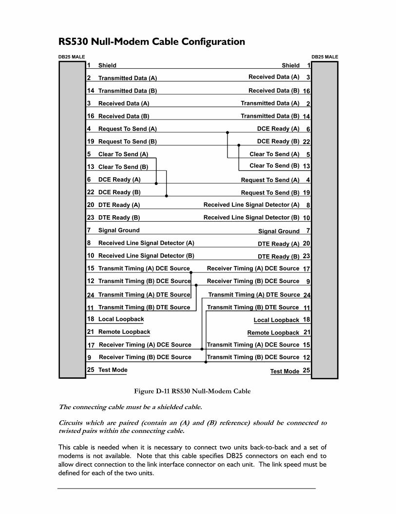
RS530 Null-Modem Cable Configuration
Shield
Transmitted Data (A)
Transmitted Data (B)
Received Data (A)
Received Data (B)
Request To Send (A)
Request To Send (B)
Clear To Send (A)
Clear To Send (B)
DCE Ready (A)
DCE Ready (B)
DTE Ready (A)
DTE Ready (B)
Signal Ground
Received Line Signal Detector (A)
Received Line Signal Detector (B)
Transmit Timing (A) DCE Source
Transmit Timing (B) DCE Source
Receiver Timing (A) DCE Source
Receiver Timing (B) DCE Source
Local Loopback
Remote Loopback
Transmit Timing (A) DTE Source
Transmit Timing (B) DTE Source
Test Mode
Clear To Send (A)
DB25 MALE
1
2
14
3
16
4
19
5
13
6
22
20
23
7
8
10
15
12
17
9
18
21
24
11
25
DB25 MALE
1
3
16
2
14
6
22
513
4
19
8
10
7
20
23
24
11
17
9
18
21
15
12
25
Transmitted Data (A)
Received Data (A)
Transmitted Data (B)
Received Data (B)
DCE Ready (A)
DCE Ready (B)
Clear To Send (B)
Request To Send (A)
Request To Send (B)
Received Line Signal Detector (A)
Received Line Signal Detector (B)
DTE Ready (A)
DTE Ready (B)
Signal Ground
Transmit Timing (A) DTE Source
Transmit Timing (B) DTE Source
Local Loopback
Remote Loopback
Receiver Timing (A) DCE Source
Transmit Timing (A) DCE Source
Transmit Timing (B) DCE Source
Test Mode
Shield
Receiver Timing (B) DCE Source
Figure D-11 RS530 Null-Modem Cable
The connecting cable must be a shielded cable.
Circuits which are paired (contain an (A) and (B) reference) should be connected totwisted pairs within the connecting cable.
This cable is needed when it is necessary to connect two units back-to-back and a set ofmodems is not available. Note that this cable specifies DB25 connectors on each end toallow direct connection to the link interface connector on each unit. The link speed must bedefined for each of the two units.

RS530 To RS449 Conversion Cable
Transmitted Data (A)
Data Terminal Ready (A)
Transmitted Data (B)
Data Terminal Ready (B)
Received Data (A)
Receiver Signal Element Timing (DCE Source) (A)
Received Data (B)
Receiver Signal Element Timing (DCE Source) (B)
Received Line Signal Detector (A)
Transmit Signal Element Timing (DCE Source) (A)
Received Line Signal Detector (B)
Transmit Signal Element Timing (DCE Source) (B)
Data Set Ready (A)
Transmit Signal Element Timing (DTE Source) (A)
Data Set Ready (B)
Transmit Signal Element Timing (DTE Source) (B)
Request to Send (A)
Signal Ground
Request to Send (B)
Shield
Clear to Send (A)
Clear to Send (B)
DB25 MALE
2
20
14
23
3
17
16
9
8
15
10
12
6
24
22
11
4
7
19
1
5
13
DB37 MALE/FEMALE
4
12
22
30
6
8
24
26
13
5
31
23
11
17
29
35
7
19
25
1
9
27
Figure D-12 RS530 to RS449 Conversion Cable
The connecting cable must be a shielded cable.
Circuits which are paired (contain an (A) and (B) reference) should be connected totwisted pairs within the connecting cable.
This cable is used to connect an RS530 link to an RS449 device. The cable converts from aDB25 connector to a DB37 connector.

V.11/X.21 Null-Modem Cable Configuration
Figure D-13 V.11/X.21 Null-Modem Cable
The connecting cable must be a shielded cable.
Circuits which are paired (contain an (A) and (B) reference) should be connected totwisted pairs within the connecting cable.
This cable is needed when it is necessary to connect two units back-to-back and a set ofmodems is not available. Note that this cable specifies DB15 connectors on each end toallow direct connection to the link interface connector on each unit. The link speed must bedefined for each of the two units.
When using this cable to connect two units back-to-back, a jumper must be installed onpinheaders W8 and W9 on one of the V.11/X.27 interface modules. This allows thatparticular module to generate the required timing signals.


![~V4 ffi~~~~~@ti~T~ ~~~~~(g~ ©©lMi]lMi]~[M[Q) …](https://static.fdocuments.net/doc/165x107/61cc5ca722583c59e2144e35/v4-ffitit-g-lmilmimq-.jpg)


