Bricscad V8 - User Guide - civilstructural.com.my · Isometric Snap and Grid ... Bricscad V8 - User...
268
Bricscad V8 – User Guide
Transcript of Bricscad V8 - User Guide - civilstructural.com.my · Isometric Snap and Grid ... Bricscad V8 - User...

Bricscad V8 – User Guide

Table Of Contents Bricscad .......................................................................................................................1
Welcome to Bricscad....................................................................................................1
Understanding Bricscad................................................................................................2
Installation platforms and levels ....................................................................................3
Differences between Bricscad for Linux, Bricscad Classic and Pro: .................................3
Upgrading a Classic version to a Pro version....................................................................4
Silent Installation (MS-Windows only) ............................................................................7
What's New...................................................................................................................8
What's New................................................................................................................8
Drawing Explorer ........................................................................................................9
Drawing Explorer......................................................................................................9
Exploring Blocks .......................................................................................................12
Exploring Blocks.....................................................................................................12
Blocks Explorer display options ..............................................................................13
Exploring Xrefs .........................................................................................................16
Exploring Xrefs ......................................................................................................16
Xrefs Explorer display options................................................................................16
Exploring Images ......................................................................................................20
Exploring Images ...................................................................................................20
Images Explorer display options.............................................................................20
Placing images in a drawing ..................................................................................23
Load / Unload images...........................................................................................25
Removing images ................................................................................................27
Bricscad Properties Bar ..............................................................................................28
Bricscad Properties Bar ...........................................................................................28
Settings Dialog .........................................................................................................38
Settings Dialog ......................................................................................................38
User Interface .............................................................................................................42
The Bricscad Application Window.................................................................................42
The Bricscad Application Window ..............................................................................42
Toolbars ..................................................................................................................46
Toolbars................................................................................................................46
Toolbar Flyouts.................................................................................................47
Defining your preferences .............................................................................................52
Overview .................................................................................................................52
Drawing Accurately ......................................................................................................54
Overview .................................................................................................................54
Coordinate Input.......................................................................................................55
Coordinate Input ....................................................................................................55
Working with Cartesian coordinates........................................................................55
Working with cylindrical coordinates .......................................................................56
Working with spherical coordinates.........................................................................57
Snap and Grid ..........................................................................................................59
Using Snap and Grid ...............................................................................................59
Isometric Snap and Grid ....................................................................................59
Command Options ............................................................................................61
ii

Table Of Contents
Entity Snaps.............................................................................................................64
Entity Snaps ..........................................................................................................64
Entity Snap Modes ............................................................................................66
Using Orthogonal Mode ..............................................................................................69
Polar Tracking ..........................................................................................................70
Polar Tracking........................................................................................................70
Entity Snap Tracking .................................................................................................72
User Coordinate Systems ...........................................................................................74
User Coordinate Systems.........................................................................................74
Command Options ............................................................................................75
Direct Distance Entry.................................................................................................78
Viewing your drawing ...................................................................................................79
Overview .................................................................................................................79
View manipulation using the mouse .............................................................................81
View manipulation using the mouse ..........................................................................81
Redrawing and Regenerating a Drawing .......................................................................83
Redrawing and Regenerating a Drawing.....................................................................83
Panning ...................................................................................................................85
Panning ................................................................................................................85
Command Options ............................................................................................85
Zooming ..................................................................................................................87
Zooming ...............................................................................................................87
Command Options ............................................................................................87
View Rotation ...........................................................................................................89
View Rotation ........................................................................................................89
Command Options ............................................................................................91
Define a View ...........................................................................................................92
Command Options ...............................................................................................93
Named Views ...........................................................................................................95
Named Views.........................................................................................................95
Command Options ............................................................................................95
Workspaces..............................................................................................................98
Workspaces...........................................................................................................98
Switching between workspaces..............................................................................98
Model Space Viewports ............................................................................................ 100
Model Space Viewports.......................................................................................... 100
Command Options .......................................................................................... 102
Paper space viewports ............................................................................................. 104
Paper space viewports........................................................................................... 104
Command Options .......................................................................................... 107
Properties ...................................................................................................... 108
Layouts ................................................................................................................. 111
Layouts............................................................................................................... 111
Drawing Entities ........................................................................................................ 114
Entity Creation Settings ........................................................................................... 114
Overview ............................................................................................................ 114
Fill Mode ............................................................................................................. 115
Entity Color ......................................................................................................... 117
iii

Bricscad V8 - User Guide
Entity Color ...................................................................................................... 117
Index Colors .................................................................................................. 117
True Colors .................................................................................................... 118
Lineweight........................................................................................................... 121
Lineweight........................................................................................................ 121
Linetype.............................................................................................................. 124
Entity Linetype .................................................................................................. 124
Current Layer ...................................................................................................... 128
Drawing 2D Entities................................................................................................. 129
Overview ............................................................................................................ 129
Lines .................................................................................................................. 131
Command Options .......................................................................................... 132
Rays................................................................................................................... 133
Command Options .......................................................................................... 133
Infinite Lines ....................................................................................................... 135
Command Options .......................................................................................... 135
Polylines ............................................................................................................. 137
Polylines........................................................................................................... 137
Splines ............................................................................................................... 142
Command Options .......................................................................................... 143
Freehand ............................................................................................................ 144
Command Options .......................................................................................... 145
Circles ................................................................................................................ 146
Circles ............................................................................................................. 146
Arcs ................................................................................................................... 148
Arcs................................................................................................................. 148
Ellipses ............................................................................................................... 151
Ellipses ............................................................................................................ 151
Elliptical Arcs ....................................................................................................... 154
Elliptical Arcs .................................................................................................... 154
Rectangles .......................................................................................................... 156
Command Options .......................................................................................... 156
Polygons ............................................................................................................. 158
Command Options .......................................................................................... 158
Traces ................................................................................................................ 160
Donuts................................................................................................................ 161
Command Options .......................................................................................... 162
Planes ................................................................................................................ 163
Command Options .......................................................................................... 163
Revision Clouds.................................................................................................... 165
Points ................................................................................................................. 168
Points .............................................................................................................. 168
Working with hatches .............................................................................................. 171
Hatching Overview ............................................................................................... 171
Using Boundary Hatch........................................................................................... 173
Command Options .......................................................................................... 175
Editing a hatch..................................................................................................... 178
Modifying Entities ...................................................................................................... 179
iv

Table Of Contents
Overview ............................................................................................................... 179
Modifying Commands Overview .............................................................................. 179
Entity Modification Settings.................................................................................... 181
Selecting Entities .................................................................................................... 182
Selection Settings................................................................................................. 182
Selection Methods ................................................................................................ 184
Selection Methods.............................................................................................. 184
Rearranging Entities ................................................................................................ 186
Moving Entities .................................................................................................... 187
Moving Entities.................................................................................................. 187
Moving entities in a drawing ............................................................................. 187
Moving entities between drawings ..................................................................... 188
Rotating Entities................................................................................................... 191
Rotating Entities ................................................................................................ 191
Adjusting the Draw Order ...................................................................................... 194
Command Options .......................................................................................... 194
Aligning Entities ................................................................................................... 196
Aligning Entities ................................................................................................ 196
Changing Entities ................................................................................................. 199
Copying Entities...................................................................................................... 200
Copying Entities in a Drawing................................................................................. 200
Command Options .......................................................................................... 200
Copying Entities Between Drawings......................................................................... 202
Copying Entities Between Drawings ...................................................................... 202
Making Parallel Copies........................................................................................... 204
Command Options .......................................................................................... 204
Mirroring Entities.................................................................................................. 206
Mirroring Entities ............................................................................................... 206
Arraying Entities................................................................................................... 208
Arraying Entities................................................................................................ 208
Arraying Entities in 3D .......................................................................................... 213
Arraying Entities in 3D........................................................................................ 213
Resizing Entities...................................................................................................... 216
Extending Entities................................................................................................. 216
Command Options .......................................................................................... 216
Changing the length of an entity............................................................................. 218
Changing the length of an entity .......................................................................... 218
Stretching Entities ................................................................................................ 221
Stretching Entities ............................................................................................. 221
Trimming Entities ................................................................................................. 223
Command Options .......................................................................................... 223
Scaling Entities .................................................................................................... 225
Breaking and Joining Entities .................................................................................... 227
Breaking Entities .................................................................................................. 227
Command Options .......................................................................................... 227
Joining Entities..................................................................................................... 228
Chamfering and Filleting .......................................................................................... 230
Overview ............................................................................................................ 230
v

Bricscad V8 - User Guide
vi
Chamfering Entities .............................................................................................. 232
Chamfering Entities............................................................................................ 232
Filleting Entities ................................................................................................... 236
Filleting Entities................................................................................................. 236
Editing Polylines...................................................................................................... 239
Overview ............................................................................................................ 239
Converting an entity into a polyline ......................................................................... 240
Opening and closing polylines................................................................................. 241
Joining Polylines................................................................................................... 242
Changing the polyline width ................................................................................... 243
Changing the polyline width ................................................................................ 243
Editing polyline vertices......................................................................................... 245
Editing polyline vertices ...................................................................................... 245
Curving and decurving polylines ............................................................................. 250
Setting the Linetype generation mode ..................................................................... 251
Editing polylines in the Properties bar...................................................................... 253
Converting Entities .................................................................................................. 255
Exploding entities ................................................................................................. 255
Creating Regions .................................................................................................. 256
Flattening Entities................................................................................................. 257
Measuring and Dividing Entities................................................................................. 258
Measuring Entities ................................................................................................ 258
Dividing Entities ................................................................................................... 261

Bricscad
Welcome to Bricscad
Congratulations on your purchase of Bricscad. Whether you're a novice user or an experienced CAD professional, you'll soon be creating drawings using the numerous productivity-enhancing features in the software. These features include:
• A familiar Windows environment.
• The ability to work with multiple open documents.
• Unparalleled DWG compatibility.
These are just a few of the many features that we have included in the program to make the transition into CAD-based drawing a smooth one for new users. We have also incorporated many features that experienced CAD users have been requesting for years in a drawing package. You have chosen an affordable, high-quality software program to produce your drawings. We are conviced you will be pleased with the results!
We encourage you to take a few moments to familiarize yourself with the information in this Help system. We have organized the following quick-reference topics to give you an overview of some of the program's features and to assist you in using the Bricscad Help system.
Because Bricscad can read, write, and display DWG files without conversion, it is an obvious choice for Autodesk® AutoCAD users. But the program provides other compatibility and productivity features that you will find indispensable.
Bricscad is a powerful drawing program that gives you the ability to create professional two-dimensional drawings and three-dimensional designs. But don't take our word for it, see a few samples for yourself!
Bricscad is designed for anyone who wants a fast and efficient CAD program with the power and versatility of standard programs such as Autodesk® AutoCAD® or MicroStation® by Bentley Systems Inc., at an affordable price. Using today's advanced technology, Bricscad integrates the Microsoft® Windows® interface with a powerful CAD engine.
1

Bricscad V8 - User Guide
Understanding Bricscad
Bricscad is designed for anyone who wants a fast and efficient CAD program with all the power and versatility of standard programs such as Autodesk® AutoCAD® , or MicroStation® by Bentley Systems®, at an affordable price. Using today's advanced technology, Bricscad integrates the Microsoft® Windows interface with a powerful CAD engine.
Bricscad provides unparalleled compatibility with AutoCAD®, using most of the same file formats including those for drawings (.dwg files), linetypes, hatch patterns, and text styles. You can also use AutoCAD® menu files and run Autodesk® AutoLISP® programs. If you have written your own ADS (AutoCAD Development System® by Autodesk®) programs, simply recompile them to link with the Bricscad libraries. Many third-party ADS programs already support Bricscad. If you have a program that is not already supported, ask your software vendor to provide a Bricscad-compatible version of their program.
Bricscad is more compatible with the AutoCAD® program than any other CAD product, delivers additional tools with advanced CAD features, and has a seamless Microsoft® Windows® integration. This powerful program provides a superb combination of features for CAD users like architects, engineers, and designers.
Bricscad incorporates all the standard features found in other CAD programs, along with features and capabilities you won't find anywhere else. Its multiple-document interface (MDI) lets you open and work with several drawings at the same time. You can easily copy drawing entities between drawings. In addition, the powerful Bricscad Explorer lets you manage information and settings and quickly copy layers, linetypes, and other information between drawings. The brand new Settings Dialog lets you manage all settings variables in a single window. With the powerful search tool you can find any setting within seconds.
2

Bricscad
Installation platforms and levels
Depending on the license you have, Bricscad can be installed on 2 different platforms : MS-Windows or Linux.
For the Windows version you have the choice between 2 different levels : Classic or Pro.
Differences between Bricscad for Linux, Bricscad Classic and Pro:
Windows Feature Linux
Classic Pro
Component Object Model (COM)
True Color
Apparent & Extended Intersection Snap
SnapTrack
eDrop
ActiveX, Including in-place-editing
LISP encryption
Quick Render (future release)
Raster Image Support
ACIS Viewing
ACIS Editing
Visual Basic for Applications (VBA)
partly available
not available
available
This help file describes all the features. So some of the features do not apply to the Linux or Classic version.
NOTE In Evaluation mode (30 days trial period) Bricscad Pro is installed as a Classic version because the Pro features are not installed with a trial license key. After the trial period you need to run the installation again in order to install a Pro license key and the specific Pro features: VBA and ACIS Editing.
3

Bricscad V8 - User Guide
Upgrading a Classic version to a Pro version
It is possible to install a Bricscad Pro version without uninstalling an existing Classic version. You only need a Bricscad Pro installer (or the installer from a Bricscad CD) and a valid Pro license key.
NOTE A valid Pro License key must be entered before or during the installation (and not after). This because the licensed features are installed only if they are authorized by the active licence key !
To upgrade an installed Classic version to the Pro version
1. Run the Bricscad Pro installer (or the installer from a Bricscad CD).
2. Select the Modify option.
3. Click the Next button.
4. Accept the license agreement, then press the Next button.
5. In the Licensing Information dialog box, click the Modify... button.
4

Bricscad
6. Enter the new Pro licence key in the License Key field to replace the already installed
Classic license key.
If the licence key was sent to you by mail, it is recommended to copy/paste the key from the
email message into the License Key field.
7. Press the OK button to confirm the license key.
8. Press the OK button on the License Information dialog box.
9. Select the Pro features: ACIS Editing and VBA .
These features are only selected if a Pro licence key was previously installed.
Do not unselect other (installed) features : unselect a feature means uninstall it !
7. Click the Next button to finalize the installation.
5

Bricscad V8 - User Guide
The Pro features VBA (menu Tools > Visual Basic... > Visual Basic Editor.) and ACIS Editing (menu View > Toolbars > Solids Editing) are available now .
NOTE In Evaluation mode (30 days trial period) Bricscad Pro is installed as a Classic version because the Pro features are not installed with a trial license key. After the trial period you need to run the installation again in order to install a Pro license key and the specific Pro features: VBA and ACIS Editing.
6

Bricscad
7
Silent Installation (MS-Windows only)
Silent installations are installations that run without a user interface. A normal (non-silent) installation receives the necessary input from the user in the form of responses to dialog boxes. However, a silent installation does not prompt the end user for input. Instead, a silent installation must get its user input from a response file (.iss file).
A response file contains information that an end user would ordinarily enter as responses to dialog boxes when running a normal installation. During a silent installation (when the user runs Setup.exe with the /s switch), Setup.exe reads the necessary input from the response file at run time.
The format of response files resembles that of an .ini file, but response files have the .iss extension. A response file is a plain text file consisting of sections containing data entries.
Creating a response file
To create a response file, run Setup.exe with the /r switch, which runs the installation normally, and additionally creates the response file used by a silent installation. By default, the response file is called Setup.iss, and is created in the Windows or WinNT folder. To specify a different name or location for the response file, use the /f1"ISS file path" switch to Setup.exe.
Running a silent installation
To run an installation silently based on the contents of a response file, the end user runs Setup.exe with the /s switch in combination with the /f1"ISS file path" switch to specify the location of the response file.
A silent installation program does not display a dialog if an error occurs. Instead, status information for the silent installation is recorded (by default) in a file called Setup.log, created in the same folder as the response file being used. The end user can specify a different name and location for the log file using the /f2"LOG file path" switch to Setup.exe.

What's New
What's New
Compared to Bricscad V7 the following is new in V8:
• Drawing Explorer
• Xref Explorer integrated in the Drawing Explorer
• Image Explorer integrated in the Drawing Explorer
• Properties bar
• Settings dialog
8

What's New
Drawing Explorer
Drawing Explorer
The new drawing explorer window consists of 4 sub-windows:
• Open Drawings: a list of all drawings that are currently open
• Details: the details of the selected drawing or the details of the selected category in a drawing, e.g. layers, blocks, images, ...
• Drawings: your favorite drawing folders
• Preview: a preview of the selected drawing or block
Go to top
How to open the drawing explorer
To open the Drawing Explorer window to one of the following:
• Double click the Layer field in the Status Bar. The Drawing Explorer window opens showing the details of the Layers in the current drawing.
9

Bricscad V8 - User Guide
• Choose a Settings Category in the Settings menu. The Drawing Explorer window opens showing the details of the selected category.
Go to top
Opening a drawing
To open a drawing using the Drawing Explorer do the following
1. Launch the Drawing Explorer.
2. In the Drawings sub-window browse to the folder of the drawing.
3. Double click the drawing.
The drawing opens, while the Drawing Explorer window stays open.
4. (optional) Repeat steps 2 and 3 to open more drawings.
5. Close the Drawing Explorer.
10

What's New
NOTE When you select a drawing, a preview displays in the Preview sub-window.
Go to top
Adding a drawing folder
1. In the Drawings sub-window of the Drawing Explorer main window click Add Folder...
The Browse For Folder window opens.
2. In the Browse For Folder window do one of the following:
• To add an existing folder: select the folder you want to add.
• To add a new folder: click the button.
3. Click the OK button.
The folder is added.
NOTE The parent folder(s) of the selected folder is (are) greyed out in the drawing folder tree. Drawings in such folders cannot be accessed.
Go to top
11

Bricscad V8 - User Guide
Exploring Blocks
Exploring Blocks
In the Blocks Explorer you can:
• Insert blocks ( ) in the current drawing
• Create new blocks ( )
• Delete blocks ( )
• Save a block as a (new) drawing ( )
• Insert Drawings as a block ( )
• Cut ( ) or Copy ( ) a block, then Paste ( ) the block in another drawing
Open the Blocks Explorer
To open the Blocks Explorer do one of the following:
• Choose Blocks in the Settings menu.
• Select Blocks in the Open Drawings sub-window of the Drawing Explorer.
go to top
12

What's New
Blocks Explorer display options
You can choose between Detail View (list) and Icon View (thumbnails) to see the blocks in the current drawing.
Open the Detail View of the Blocks Explorer
Click the Detail View button ( ) in the Drawing Explorer toolbar. The Detail View button is
now pressed ( ), indicating the block details are displayed.
The selected block displays in the Preview sub-window of the Drawing Explorer.
Detail View of the blocks in the current drawing
go to top
Open the Icon View of the Blocks Explorer
Click the Icon View button ( ) in the Drawing Explorer toolbar. The Icon View button is now
pressed ( ), indicating the block icons are displayed.
The selected block displays in the Preview sub-window of the Drawing Explorer.
13

Bricscad V8 - User Guide
Icon View of the blocks in the current drawing
go to top
Insert a block
1. Launch the Block Explorer.
2. (optional) Choose either Detail View ( ) or Icon View ( ).
3. Select the block.
4. Click the Insert Block button ( ) in the Block Explorer toolbar.
The Block Explorer window closes.
5. Insert the block in the drawing.
The Block Explorer windows opens.
6. (optional) Repeat steps 2 through 5 to insert more blocks.
7. Close the Block Explorer window.
NOTE Instead of clicking the Insert Block tool button in step 4 you can also:
• right click and select Insert from the context menu when in Detail View;
14

What's New
• double click the block when in Icon View.
go to top
15

Bricscad V8 - User Guide
Exploring Xrefs
Exploring Xrefs
In the Xrefs Explorer you can:
• Attach Xrefs ()
• Detach Xrefs( )
• Reload Xrefs( )
• Unload Xrefs( )
• Bind Xrefs( )
Open the Xrefs Explorer
To open the Xrefs Explorer do one of the following:
• Choose Xrefs in the Settings menu.
• .Select External References in the Open Drawings sub-window of the Drawing Explorer.
go to top
Xrefs Explorer display options
You can choose between Detail View (list), Icon View and Tree View to see the xrefs in the current drawing.
16

What's New
NOTE Bricscad searches for external references in the folder of the parent drawing first. If the drawing is not found there, Bricscad looks in the Saved Path folder. If the drawing is not found there either, (! Not Found) displays in the Saved Path field.
Open the Detail View of the Xrefs Explorer
Click the Detail View button ( ) in the Drawing Explorer toolbar. The Detail View button is
now pressed ( ), indicating the Xref details are displayed.
The selected Xref displays in the Preview sub-window of the Drawing Explorer.
Detail view of the Xrefs in the current drawing
go to top
Open the Icon View of the Xrefs Explorer
Click the Icon View button ( ) in the Drawing Explorer toolbar. The Icon View button is now
pressed ( ), indicating the Xref icons are displayed.
The selected Xref displays in the Preview sub-window of the Drawing Explorer.
External References that were not found display with the default icon ( ) in the Details sub-window of the Drawing Explorer window.
17

Bricscad V8 - User Guide
Icon view of the Xrefs in the current drawing
go to top
Open the Tree View of the Xrefs Explorer
Click the Tree View button ( ) in the Drawing Explorer toolbar. The Tree View button is now
pressed ( ), indicating the Xref tree is displayed.
The selected Xref displays in the Preview sub-window of the Drawing Explorer.
External References that were not found display with the error icon ( ) in the Details sub-window of the Drawing Explorer window.
18

What's New
Tree view of the Xrefs in the current drawing
go to top
19

Bricscad V8 - User Guide
Exploring Images
Exploring Images
In the Images Explorer you can:
• Attach images ( )
• See a preview of the attached images
• Insert images ( )
• Load / Unload inserted images
• Detach images ( )
Open the Images Explorer
To open the Images Explorer do one of the following:
• Choose Images in the Settings menu.
• Click the Image Management tool button ( ) in the Images toolbar.
• Select Images in the Open Drawings sub-window of the Drawing Explorer.
go to top
Images Explorer display options
20

What's New
You can choose between Detail View (list), Icon View and Tree View to see the images in the current drawing.
Open the Detail View of the Images Explorer
Click the Detail View button ( ) in the Drawing Explorer toolbar. The Detail View button is
now pressed ( ), indicating the image details are displayed.
The selected image displays in the Preview sub-window of the Drawing Explorer.
Detail View of the images in the current drawing
go to top
Open the Icon View of the Images Explorer
Click the Icon View button ( ) in the Drawing Explorer toolbar. The Icon View button is now
pressed ( ), indicating the image icons are displayed.
The selected image displays in the Preview sub-window of the Drawing Explorer.
21

Bricscad V8 - User Guide
Icon View of the images in the current drawing
go to top
Open the Tree View of the Images Explorer
Click the Tree View button ( ) in the Drawing Explorer toolbar. The Tree View button is now
pressed ( ), indicating the image tree is displayed.
The selected image displays in the Preview sub-window of the Drawing Explorer.
22

What's New
Tree View of the images in the current drawing
go to top
Placing images in a drawing
As different form Bricscad V7, in Bricscad V8 you need to attach an image first, then insert it in the drawing. As a result, an image can be attached to a drawing, while it is not placed in the drawing yet. If you delete an image in the drawing, it will still be attached and can be inserted again.
Attach images
1. Launch the Image Explorer.
2. Click the New tool ( ) in the Drawing Explorer - Images toolbar.
The Open dialog window displays.
23

Bricscad V8 - User Guide
3. In the Open dialog window browse to the image.
4. Do one of the following:
• Click the Open button.
• Double click the image.
The image is attached to the current drawing. A preview of the image shows in Preview sub-window of the Images Explorer.
go to top
Insert images
1. Launch the Image Explorer.
2. Select the image.
3. Do one of the following:
• Click the Insert tool ( ) in the Drawing Explorer - Images toolbar.
• Right click and choose Insert in the context menu.
24

What's New
The Attach Image dialog opens.
4. On the Attach Image dialog:
• (option) Select a Position File.
• Specify an insertion point or select the Specify on-screen check box.
• Specify scale or select the Specify on-screen check box.
• Specify rotation angle or select the Specify on-screen check box.
5. Click the OK button.
6. If any of the Specify on-screen options is selected, the image is inserted at the desired
insertion point, scale and rotation angle;
else
Specify the insertion point, scale and/or rotation angle on-screen.
NOTE The Attach Raster Image tool in the Images toolbar simultaneously attaches and inserts the image.
go to top
Load / Unload images
When an image is attached and then inserted in the drawing, you can unload the image to temporarily remove it. Unloaded images are still inserted in the drawing, but they no longer display. If the Imageframe setting is on, the frame still displays though.
Modify the Image Frame setting
1. Click the Image Frame tool ( ) in the Images toolbar.
25

Bricscad V8 - User Guide
2. Choose On or Off on the Imageframe option box.
The display of the image frames changes accordingly.
go to top
Load / Unload a single image
1. Launch the Image Explorer.
2. For the image you want to load or unload, click the check box in the Loaded column.
3. If the Regen On/Off button ( ) is not pressed, click the Regen tool ( ) in the
Images Explorer toolbar.
NOTE It is not necessary to select the image first in step 2.
go to top
Load / Unload multiple images
1. Launch the Image Explorer.
2. Select the images you want to load or unload.
3. For one of the selected images, click the check box in the Loaded column.
26

What's New
All selected images will be loaded or unloaded simultaneously.
4. If the Regen On/Off button ( ) is not pressed, click the Regen tool ( ) in the
Images Explorer toolbar.
NOTE Press and hold the Ctrl key to select multiple images.
go to top
Removing images
Since an image is first attached, then inserted in the drawing, you can delete an image, without detaching it.
Detach images
1. Launch the Image Explorer.
2. Select the image(s) that you want to detach.
3. Do one of the following
• Click the Delete tool ( ) in the Images Explorer toolbar.
• Right click and select Delete in the context menu.
NOTE Press and hold the Ctrl key to select multiple images.
go to top
27

Bricscad V8 - User Guide
Bricscad Properties Bar
Bricscad Properties Bar
In the Bricscad Properties Bar you can:
• Set the current properties: color, layer, linetype, linetype scale and lineweight
• See the properties of a single entity
• Edit the properties of a single entity
• Edit endpoints of lines and and vertices of polylines graphically
• Edit the shared properties of a selection set
Open the Properties Bar
Do one of the following.
• Right click when the cursor is on a toolbar.
A context menu displays.
The marked items in the context menu are currently open.
Select Properties Bar in the context menu.
• Double click an entity. The Bricscad Properties Bar opens, showing the properties of the
selected entity.
• Click the Properties tool button ( ) on the Modify toolbar.
• Choose Properties in the Modify menu.
• Type properties in the command window, then press Enter.
28

What's New
NOTE The Bricscad Properties Bar can be either floating or docked.
To dock the Bricscad Properties Bar, drag it by its title bar to either the left or right hand side of the Bricscad application window.
go to top
Adjust the size of the Bricscad Properties Bar
1. Move the cursor over one of the edges of the Bricscad Properties Bar (1).
The cursor turns into a double-headed arrow.
2. Press and hold the left mouse button to drag the edge of the Bricscad Properties Bar.
29

Bricscad V8 - User Guide
3. Move the cursor over the boundary between the Setting Names and the Setting Fields
columns (2).
The cursor turns into a double-headed arrow.
4. Press and hold the left mouse button to drag the boundary.
NOTE When docked, only the left (or right) edge of the Bricscad Properties Bar is adjustable.
Set the current properties in the Bricscad Properties Bar
1. (option) Click on Color,
then click the down arrow button to select a color.
2. (option) Click on Layer,
30

What's New
then click the down arrow to select a layer.
3. (option) Click on Linetype.
then click on the down arrow to select a linetype.
31

Bricscad V8 - User Guide
4. (option) Click on Linetype scale,
then type the new value in the Linetype scale field.
5. (option) Click on Lineweight,
then click on the down arrow to select a lineweight.
go to top
See the properties of a single entity
32

What's New
1. Select the entity.
The entity's properties display in the Bricscad Properties Bar.
Properties of a circle
2. (option) Press the Escape key to deselect the previous entity and select another entity.
The newly selected entity's properties display in the Bricscad Properties Bar.
33

Bricscad V8 - User Guide
Properties of a block
3. Press the Escape key to stop.
go to top
Edit the properties of a single entity
1. Select the entity.
The entity's properties display in the Bricscad Properties Bar.
2. Click the property you want to modify.
The settings field of the selected property is activated.
34

What's New
3. Type a new value in the settings field of the selected property or choose a setting from
the list box, then press the Enter key or select another property.
The entity is updated.
4. (option) repeat steps 2 and 3 to modify another property.
5. Press the Escape key to stop.
NOTES • Properties of which the value displays in grey cannot be modified.
• Step 3: Properties (such as the General properties), which are chosen from a list are updated instantly.
go to top
Edit endpoints of a line graphically
1. Select the line.
2. On the Bricscad Properties Bar, under Geometry, select either Start point or End point.
An X indicates the point being edited.
3. Click the Define button ( ).
4. In the drawing, specify the point graphically.
The XYZ coordinates of the point are adjusted accordingly.
5. Press the Escape key to stop.
NOTE This procedure also applies to the edit the insertion point of blocks.
Edit vertices of polyline graphically
1. Select the polyline..
2. On the Bricscad Properties Bar under Geometry, select Vertex.
35

Bricscad V8 - User Guide
3. Click the Next/Previous arrow buttons to select a vertex.
An X indicates the vertex being edited.
4. Under Vertex select Position.
5. Click the Define button ( ).
6. In the drawing, specify the point graphically.
The XYZ coordinates of the point are adjusted accordingly.
7. Press the Escape key to stop.
go to top
Edit the shared properties of a selection set
1. Select the entities.
The shared properties display in the Bricscad Properties Bar.
2. Click the property you want to modify.
The settings field of the selected property is activated.
3. Type a new value in settings field of the selected property or choose a setting from the
list box, then press the Enter key or select another property.
All selected entities are updated simultaneously.
4. (option) Repeat steps 2 and 3 to modify another property.
5. Press the Escape key to stop.
NOTES • *Varies* displays for shared properties which are defined differently. If you edit such property, all entities in the selection set will be equally defined for this property.
• Step 3: Properties (such as the General properties), which are chosen from a list are updated instantly.
36

What's New
go to top
37

Bricscad V8 - User Guide
Settings Dialog
Settings Dialog
In the Settings Dialog you can:
• Check the current value of all settings.
• Edit settings.
• Find settings.
• Export the settings in a text file
Open the Settings dialog
1. Choose Settings in the Settings menu.
38

What's New
2. (option) Choose a display mode by clicking the corresponding button in the Settings
toolbar.
Categorized ( )
Lists the settings by category: Drawing, Dimensions and Program Options.
Alphabetical ( )
Lists the settings alphabetically.
3. (option) Choose a category:
Drawing ( )
Opens the Categorized view mode, with the Drawing settings tree expanded.
Dimensions ( )
Opens the Categorized view mode, with the Dimension settings tree expanded.
Program Options ( )
Opens the Categorized view mode, with the Program Options settings tree expanded.
go to top
Edit settings
1. Open the Settings Dialog.
2. Select a setting.
39

Bricscad V8 - User Guide
1 Class: Drawing, Dimensions or Program Options
2 Category (expanded)
3 Sub-category (expanded)
4 Group (expanded)
5 Setting and its current value
6 Options list
7 Group (collapsed)
8 Command (to define the setting in the command bar)
9 Settings Name
10 Settings Description
11 Preview
12 Settings Type ( = hard coded; = user-defined)
13 Where is the setting saved? ( = drawing; = registry; = not saved)
14 ( ) Indicates a setting is available in Bricscad only.
4. Click the settings field to edit the setting.
5. (option) Repeat steps 3 and 4 to edit more settings.
6. Close the Settings window.
go to top
Find Settings
1. Open the Settings Dialog.
2. (option) Click the Find Options button ( ) to open the open the Find Setting dialog
where you can set the search options.
40

What's New
3. Type the search string in the Search field.
The first setting matching the content of the search field highlights.
4. (option) Click the next ( ) or previous ( ) button to browse through the matching
settings.
go to top
Export Settings
1. Click the Export tool ( ) on the Settings toolbar.
The Export Settings window opens.
2. Type a name in the File name field.
3. (option) Select a folder.
By default the export file is saved in the Languages/en_US folder of the Bricscad
installation folder
e.g. C:\Program Files\Bricsys\Bricscad\Languages\en_US.
4. Click the Save button on the Export Settings window.
All Settings are exported in a CSV (Comma Separated Values) text file, which can be
opened in Microsoft® Excel®.
go to top
41

User Interface
The Bricscad Application Window
The Bricscad Application Window
The layout of the Bricscad application window can be fully customized.
You can:
• open / close the command window
• open / close the status bar
• modify drawing settings in the status bar
• display / hide scroll bars
Components of the Bricscad application window:
1. Menu Bar
2. Toolbar (docked)
3. Drawing windows
4. Drawing viewports
5. Bricscad Properties Bar
6. Toolbar (floating)
7. Command window
8. Status Bar
42

User Interface
Open / Close the command bar
1. (option) Do one of the following:
• Choose Command Bar in the View Menu.
• Move the cursor to a docked toolbar, then right click and choose Command Bar in the
context menu.
The Command Window closes if it was open and vice versa.
2. (option) Type cmdbar.
The CMDBAR context menu opens.
3. Choose one of the options on the Cmdbar context menu.
NOTES • You can modify the height of the docked command window by dragging its top edge, when docked Lower or bottom edge, when docked Upper.
• The size of a floating command bar can be adjusted by dragging one of its edges.
• When the command bar is closed, command options and keyboard entries display in the status bar.
Open / Close the status bar
Do one of the following:
• Choose Status Bar in the View Menu.
• Press the F10 function key on the keyboard.
The Status Bar closes if it was open and vice versa.
Working with the status bar
The Status Bar fields are:
1. Status:
• displays the status of the software.
• when the cursor is in a menu or on a toolbar: gives a brief description of the tool or
menu item.
43

Bricscad V8 - User Guide
• when the command window is closed: displays the tool options and keyboard entry.
2. Coordinates: displays the coordinates of the current cursor position (depending on the
setting of the COORDS variable).
3. Layer: displays the name of the current layer.
• double click to open the Layer Explorer.
• right click to select the current layer
4. Color: displays the current color.
• double click to open the Select Color dialog window.
• right click to select one of the basic colors.
5. Linetype: displays the name of the current linetype.
• double click to open the Linetype Explorer.
• right click to select the current linetype
6. Text Style: displays the name of the current text style.
• double click to open the Styles Explorer.
• right click to select the current text style.
7. Dimension Style: displays the name of the current dimension style
• double click to op en the Dimensions Settings dialog window.
• right click to select the current dimension style.
8. Snap:
• double click to toggle Snap on ( ) /off ( ).
• right click, then choose Settings to get access to the Snap and Grid settings.
9. Grid: double click to toggle the display of grid points on ( ) / off ( ) in the
current viewport.
10. Orthogonal Mode: double click to toggle Orthogonal mode on ( ) /off ( ).
Turning Orthogonal mode on automatically disables Polar Tracking.
11. Entity Snaps:
• double click to toggle Entity Snaps on ( ) / off ( ).
• right click, then choose Settings to get access to the Entity Snaps settings.
12. Polar Tracking (AutoSnap):
• double click to toggle Polar Tracking on ( ) / off ( ).
Turning Polar Tracking on automatically disables Orthogonal mode.
• right click, then choose Settings to get access to the Polar Tracking settings.
13. Snap Tracking (AutoSnap):
• double click to toggle Snap Tracking on ( ) /off ( ).
• right click, then choose Settings to get access to the Snap Tracking settings.
44

User Interface
14. Line Weight Dispaly:
• double clik to toggle the display of Line Weights On ( ) or Off ( ).
• right click, then choose On or Off to control the display of Line Weights.
15. Current Workspace.
• Tile : Model space with tiled viewports.
• M:Layout : Model space with floating viewports
• P:Layout : Paper space
16. Tablet: Initializes the use of a drawing tablet.
NOTE Orthogonal mode (field 10) is switched off if Polar Tracking (field 14) is on and vice versa.
Display or hide scroll bars
1. (option) To toggle scroll bars on / off: choose Scroll Bars in the View menu.
2. (option) Type scrollbar in the command bar, then do one of the following:
• type off in the command bar or choose Off in the context menu.
• type on in the command bar or choose On in the context menu.
• type T in the command bar or choose Toggle in the context menu.
45

Bricscad V8 - User Guide
Toolbars
Toolbars
The following toolbars are available in Bricscad.
Standard
Draw 2D
Modify
Draw Order
View
Isometric Views
Dimensions
Inquiry
Entity Data
Entity Snaps
Draw 3D
46

User Interface
Solid Editing
Solids
Rendering
Settings
Tools
Layout
Images
Entity Properties
Toolbar Flyouts
On some tool buttons a small black arrow indicates a flyout is available. A flyout holds a group of related tools. Press and hold the left mouse button to expand the flyout and choose one of the flyout tools. The tool that was last chosen remains visible in the collapsed toolbar. Each of the flyouts can also be opened as a separate toolbar.
Parent Flyout
Draw 2D Line
Polyline
Polygon
47

Bricscad V8 - User Guide
Modify Extend/Stretch
Measure/Divide
Chamfer/Fillet
View Redraw/Regen
Zoom
Real-Time Rotate
Dimensions Circles
Draw 3D 3D Faces
3D Surfaces
Settings Color
Opening a toolbar
48

User Interface
1. Place the cursor on a open toolbar, then right click.
A context menu displays.
2. Choose BRICSCAD on the context menu.
A list of all available toolbars displays. Toolbars that are already open are checked.
49

Bricscad V8 - User Guide
2. Select the toolbar on the context menu.
The toolbar opens.
3. (option) Dock the toolbar by dragging the toolbar by its title bar to one of the edges of
the Bricscad application window.
50

User Interface
51
NOTES • If you select a toolbar that was already open, it will be closed.
• To prevent a toolbar from docking, press and hold the Ctrl key while dragging the toolbar.
• Drag a toolbar by its left (or top) edge ( ) to undock.
Closing a toolbar
1. Place the cursor on a open toolbar, then right click.
A context menu displays.
2. Choose BRICSCAD on the context menu.
3. On the toolbar list click the toolbar you want to close.
NOTE You can close a floating toolbar also by clicking its Close button ( ).
Customizing toolbars
Not yet implemented.
Composing a user-defined toolbar
Not yet implemented.

Defining your preferences
Overview
In Bricscad all preferences of each user are stored in specific folders, which are called the Local root folder and the Roamable root folder.
The Local root folder contains the Template folder, where the drawing templates are saved.
The Roamable root folder contains three subfolders:
• plotconfig: where the plotter configuration files (*.pc3) are saved
• plotstyles: where the plot style table files (*.stb) and plot color table files (*.ctb) are saved
• support: where the hatch pattern files (*.pat), line style files (*.lin), alias files (*.pgp), unit files (*.unt), custom user interface files (*.cui), etc. are saved.
Roamable root folder in Windows XP C:\Documents and Settings\<user
name>\Application Data\Bricsys\Bricscad\V8\en_US
Roamable root folder in Windows Vista C:\Users\<user
name>\AppData\Roaming\\Bricsys\Bricscad\V8\en_US
When you install an update of the software, the first time you launch Bricscad after the update, the content of the User Data Cache folder (C:\Program Files\Bricsys\Bricscad\UserDataCache) is compared with the content of the Local root folder and the Roamable root folder of the current user. If you have customized the files in these folders and if one or more of the corresponding files in the User Data Cache folder are more recent, the Bricscad user file manager is launched asking you whether to keep your files or to overwrite your files with the updated files.
Using the Bricscad user file manager
1. Do one of the following:
• Select a file in the file list, then click the Yes button to overwrite or click the No button
to keep your file.
Repeat this procedure for each file in the list.
• Click the Yes to all button to replace all your files with the more recent files from
Bricscad.
• Click the Stop Copying button to keep all your files.
52

Defining your preferences
53
2. If you have decided not to update one or more files, an alert window displays.
Do one of the following:
• Click the Yes button if you want to update one of these files later.
In this case this procedure is restarted the next time you start Bricscad.
• Click the No button if you don't want to be reminded.

Drawing Accurately
Overview
In Bricscad the following drawing aids are available:
• Coordinate Input
• Snap and Grid
• Drawing Limits
• Ortho Mode
• Entity Snaps
• Polar Tracking
• Snap Tracking
• User Coordinate Systems
• Direct Distance Entry
54

Drawing Accurately
Coordinate Input
Coordinate Input
When you create entities in a drawing, they are located in relation to the drawing's underlying Cartesian coordinate system. Every drawing has a fixed coordinate system called the World Coordinate System (WCS).
You can also define arbitrary coordinate systems located anywhere in three-dimensional space. These are called user coordinate systems (UCS) and can be located anywhere in the WCS and oriented in any direction.
To specify points and distances using the keyboard you can use the following formats:
• Cartesian coordinates
• Cylindrical coordinates
• Spherical coordinates
Working with Cartesian coordinates
In the Cartesian coordinate system we use three perpendicular axis: the x-axis, the y-axis and the z-axis. All axes originate in the origin point of the coordinate system. The x- and y-axes define a horizontal plane, while the x-axis and the z-axis and the y-axis and the z-axis define vertical planes. A point is defined by its distances to the xy-, xz- and yz- planes. These distances are called the xyz-coordinates of a point.
55

Bricscad V8 - User Guide
If you want to enter the absolute Cartesian coordinates of a point, type the x-, y- and z- coordinates separated by commas: 45.5,57.3,60
If you omit the z-coordinate, the point is placed in the xy-plane (Z = 0).
If you place the @ - character in front of the entry, the coordinates are calculated with respect to the previous point: @45.5,57.3,60. This technique is called Relative Cartesian coordinates.
Using relative Cartesian coordinates to draw a rectangle
1. Launch the Rectangle command.
2. Specify the first corner of the rectangle.
3. In the command bar type: @<width>,<height>
• <width> = the width of the rectangle in drawing units, measured along the x-axis
• <height> = the height of the rectangle in drawing units, measured along the y-axis
Go to top
Working with cylindrical coordinates
In a cylindrical coordinate system we use three perpendicular axis: the x-axis, the y-axis and the z-axis. All axes originate in the origin point of the coordinate system. The x- and y-axes define a horizontal plane, while the x-axis and the z-axis and the y-axis and the z-axis define vertical planes. A point is defined using the following format: R<alpha, z.
R = distance to the origin in the xy-plane
<alpha = the angle between R and the x-axis (positive angles are measured counter clockwise)
z = the height above the xy-plane.
If the z-coordinate is omitted, cylindrical coordinates are referred to as polar coordinates.
56

Drawing Accurately
Go to top
Working with spherical coordinates
In a cylindrical coordinate system we use three perpendicular axis: the x-axis, the y-axis and the z-axis. All axes originate in the origin point of the coordinate system. The x- and y-axes define a horizontal plane, while the x-axis and the z-axis and the y-axis and the z-axis define vertical planes. A point is defined using the following format: R<alpha<beta
R = distance from the origin
<alpha = angle in the xy-plane (positive angles are measured counter clockwise)
<beta = angle measured from the xy-plane (positive angles are measured above the xy-plane)
57

Bricscad V8 - User Guide
Go to top
58

Drawing Accurately
Snap and Grid
Using Snap and Grid
Grid and snap help you to draw fast and accurately. A grid is a set of evenly spaced, visible dots that serve as a visual distance reference. The grid also indicates how far the drawing limits extend. The snap feature creates a set of evenly spaced, invisible magnetic points, which make the crosshairs move in even increments. Both grid and snap are like the intersection points of the lines on a piece of grid paper. Grid points are for visual reference only and they do not print. Snap constrains the points that you can pick with the mouse.
• Both snap and grid can be toggled on/off separately, giving you the opportunity to display the grid points, while snap is not active and vice versa.
• Both snap and grid can be set differently in each viewport.
• In each viewport you can rotate the grid using the Snap Angle setting. Isometric Snap and Grid
You can use the Isometric snap and grid option to create two-dimensional isometric drawings. With the isometric option, you can draw a simulated three-dimensional view on a two-dimensional plane, much the same as you might draw on a piece of paper. Do not confuse isometric drawings with three-dimensional drawings.
The isometric option always uses one of three preset planes, which are denoted as Left, Right and Top. You cannot alter the arrangement of these planes. If the Snap Angle is 0, the three isometric axes are 30 degrees, 90 degrees, and 150 degrees.
When you set the Snap Style setting to Isometric Snap and then set the Snap Isometric Pair setting to Left, Top or Right, the snap intervals, grid, and crosshairs align with the selected plane. The grid is always shown as isometric and uses y-coordinates to calculate the grid spacing. If the Orthogonal Mode is active, the movement of the crosshairs is constrained to the current isometric plane.
Display the Snap and Grid settings
Do one of the following to display the Snap/Grid settings in the Settings dialog:
• In the Status Bar, right click on the Snap field, then choose Settings in the context
menu.
• Open the Systems Variables dialog, then click the Drawings button ( ) on the
Systems Variables dialog.
Under Drafting, expand Coordinate Input and Snap/Grid.
Defining snap and grid spacing
1. Display the Snap/Grid settings in the Settings dialog:
59

Bricscad V8 - User Guide
2. Set the Reference Grid in the current viewport:
• Expand the Grid Unit variable.
• Type a value in the X and Y fields
3. Set the Snap Spacing:
• Expand the Snap Unit variable.
• Type a value in the X and Y fields
4. Close the System Variables dialog window.
5. If the Grid display is not turned on yet, do one of the following:
• Double click the GRID field ( ) in the Status Bar.
• Click the Grid tool ( ) on the Settings toolbar.
6. If Snap is not turned on yet, do one of the following:
• Double click the SNAP field ( ) in the Status Bar.
• Click the Snap tool ( ) on the Settings toolbar.
60

Drawing Accurately
NOTES • Although not necessary, it is recommended to set the Reference Grid as a multiple of the Snap Spacing.
• The Reference Grid only displays within the Drawing Limits. If necessary adjust the Drawing Limits.
Setting the drawing Limits
1. Do one of the following:
• Click the Drawing Limits tool button ( ) on the Settings toolbar.
• Choose Drawing Limits in the Settings menu.
• Type limits in the command bar, then press Enter.
The command bar reads: Limits are off: ON/<Lower left corner> <x,y>:
2. Do one of the following:
• Press Enter to accept the current lower left corner.
• Specify the lower left corner of the drawing limits.
The command bar reads: Upper right corner <x,y>:
3. Do one of the following:
• Press Enter to accept the current upper right corner.
• Specify the upper right corner of the drawing limits.
Command Options
Keyboard Prompt
Box Description
ON Turn limits on
Turns the drawing limits on. When the drawing limits are on it is impossible to draw outside of the limits.
OFF Turn limits off
Turns the drawing limits off.
Esc Cancel Aborts the Limits command.
Using Isometric Snap
61

Bricscad V8 - User Guide
1. Display the Snap/Grid settings in the Settings dialog:
2. Turn on the Orthogonal Mode.
3. Set the Snap Style setting to Isometric Snap.
4. In Snap isometric pair, set the appropriate drawing plane: Top, Left or Right.
Setting the Snap Angle
62

Drawing Accurately
1. Display the Snap/Grid settings in the Settings dialog:
2. Select the Snap Angle setting.
3. Type a new value in the Snap Angle setting field.
4. Close the Settings dialog.
NOTE You can also set the Snap Angle by typing snapang in the command bar.
When in a command, type 'snapang (with an apostrophe in front), to set the Snap Angle variable transparently (= without interrupting the running command).
63

Bricscad V8 - User Guide
Entity Snaps
Entity Snaps
Entity snaps enable you to quickly select exact geometric points on existing entities without having to know the exact coordinates of those points. With entity snaps, you can select the end point of a line or arc, the center point of a circle, the intersection of any two entities, or any other geometrically significant position. You can also use entity snaps to draw entities that are tangent or perpendicular to an existing entity. You can use entity snaps any time you need to specify a point.
You can work with entity snaps in one of two ways
• Enable a running entity snap that remains in effect until you turn it off by choosing an entity snap when no other command is active.
• Enable a one-time entity snap for a single selection by choosing an entity snap when another command is active. You can also use a one-time entity snap to override a running entity snap.
When using entity snaps, the program recognizes only visible entities or visible portions of entities. You cannot snap to entities on layers that have been turned off or to the blank portions of dashed lines.
When you specify one or more entity snaps, the entity Snap Aperture Box is added to the crosshairs. In addition, an icon appears adjacent to the crosshair indicating the active entity snap (Snap cursor decoration). When you move the cross hairs, the program snaps to the snap point closest to the center of the Snap Aperture Box. The Snap Marker indicates the current snap point. Press the TAB key to cycle through all possible entity snaps.
To define the Entity Snap settings
1. Do one of the following:
• Click the Settings tool button ( ) on the Settings toolbar.
• Choose Settings in the Settings menu.
• Type settings in the command bar, then press Enter.
The Settings dialog opens.
2. In the Settings dialog, expand the Program Options settings class.
3. Under Program Options expand the Display settings group, then scroll down to the
Entity Snap settings.
64

Drawing Accurately
4. Define the Entity Snap settings.
Setting Description
Snap flyover Enables Entity Snap.
Snap marker (1) Enables the display of the snap marker.
Snap marker size Sets the size of the snap marker. (default size is 6)
Snap marker thickness
Sets the thickness of the snap marker. (default thickness is 2)
Snap marker color
Sets the color of the snap marker.
Snap marker in all views
If multiple viewports are open, enables the display of the snap marker in all viewports.
Snap tooltips (2) Enables the display of the Entity Snap tooltips.
Snap aperture box (3)
Sets the size of the Entity Snap aperture box. (default size is 10)
Snap cursor decoration (4)
Enables the display of the current Entity Snap icon adjacent to the cross hairs.
65

Bricscad V8 - User Guide
NOTE You can toggle the Entity Snaps on/off by double clicking the ESNAP field in the
Status Bar.
To set the Entity Snaps
Do one of the following:
• Click the buttons on the Entity Snaps toolbar.
The buttons of the currently active Entity Snap modes are pressed.
• Press and hold the Shift key, then right click and select the entity snap mode in the
context menu.
The icons of the currently active Entity Snap modes are outlined.
When no command is active, the above procedures toggle the Entity Snap modes on/off.
When a command is active, the above procedures set a 'one shot' override of the current Entity Snap modes.
Entity Snap Modes
Name Icon Marker Description
Nearest Snap to the nearest point on an entity.
Endpoint Snap to the nearest endpoint of an entity or polyline segment.
66

Drawing Accurately
Midpoint Snap to the midpoint of an entity or polyline segment.
Center
Sncap to the center point of an arc, circle, polygon, ellipse or elliptical arc.
Snap to the center of gravity of a closed polyline.
Perpendicular
Snap to the perpendicular point of another entity. You can snap to an arc, circle, ellipse, line, polyline, infinite line, ray, spline or edge of a plane to form a perpendicular alignment with that entity or with an extension of that entity.
Tangent Snap to the point on an arc, ellipse, spline or circle that, when connected to the previous point, forms a line tangent to that entity.
Quadrant Snap to the closest quadrant of an arc, circle, ellipse, or elliptical arc.
Insertion Snap to the insertion point of an attribute, block or text entity.
Point Snap to a point entity.
Intersection Snap to the intersection of any combination of entities.
Apparent Intersection
Snap to the apparent intersection in the current view of two entities that do not intersect in three-dimensional space.
Extension Snaps to the extension of an entity or to the intersection of the extension of two entities.
Clear Turn off all entity snap modes.
Working with multiple Entity Snap modes
1. Move the cursor to the entity you want to snap.
One of the active Entity Snap modes markers display.
2. Press the TAB key.
The entity the snap point is on highlights.
3. Do one of the following:
• Click to accept the snap point.
• Press the TAB key.
The next possible Entity Snap mode marker displays.
The entity the snap point is on highlights.
4. (option) Repeat step 3 until the right snap point is found.
NOTE If you keep pressing the TAB key you can cycle through all possible snap points.
67

Bricscad V8 - User Guide
To snap to the extension of two entities
1. If not already on, turn on the Extension Entity Snap mode ( ).
2. Launch a drawing tool, e.g. Draw Line.
3. Move the cursor over the endpoint of the first entity (1).
A small cross ( ) indicates the entity is marked for extension.
4. Move the cursor over the endpoint of the second entity (2).
A small cross ( ) indicates the entity is marked for extension.
5. Move the cursor near the intersection of the extensions of the two entities.
An X indicates the intersection (3).
6. Click to accept the snap point.
NOTE You can snap to the extension of lines, polylines, arcs and elliptical arcs
68

Drawing Accurately
Using Orthogonal Mode
Orthogonal Mode restricts the movement of the cursor to be parallel to the X-axis or the Y-axis of the current coordinate system. For example, with the default 0-degree orientation (angle 0 at the "three o'clock" or "east" position), when the Orthogonal Mode setting is enabled, lines are restricted to 0 degrees, 90 degrees, 180 degrees, or 270 degrees. As you draw lines, the rubber-banding line follows either the horizontal or vertical axis, depending on which axis is nearest to the cursor: type the length of the line in the command bar, then press Enter.
NOTES • When you enable the Isometric snap style, cursor movement is restricted to orthogonal equivalents within the current isometric plane.
• You can rotate the Orthogonal Mode axes using the Snap Angle setting.
• Press and hold the Shift key to reverse the Orthogonal Mode setting.
• Orthogonal Mode is overruled by entity snaps.
To toggle Orthogonal Mode
Do one of the following:
• Double click the ORTHO field in the Status Bar.
• Press the F8 function key.
• Type ortho in the command bar, then choose the appropriate setting.
• Set the Orthogonal Mode in the Settings dialog.
NOTE Turning on Ortho Mode, automatically disables Polar Tracking.
69

Bricscad V8 - User Guide
Polar Tracking
Polar Tracking
Polar tracking assists you to draw at exact angles:
• at fixed intervals, starting from 3 O'clock (or East)
• at specific additional angles
A polar tracking path line displays from the origin point when you move the cursor close to one of the polar tracking angles. The tracking path lines display as long as the Snap Aperture box crosses a polar tracking line.
To define the Polar Tracking settings
1. Do one of the following:
• Right click on the POLAR field in the Status Bar, then right click and choose Settings in
the context menu.
• Open the Settings dialog, then expand the Coordinate input sub-category under
Drafting in the Drawing settings class.
Expand the Snap Tracking settings group.
2. Adjust the settings:
• Autosnap > 0x0001: Autosnap marker (not used, required for AutoCad® compatibility
only)
• Autosnap > 0x0002: Autosnap tooltips (not used, required for AutoCad® compatibility
only)
• Autosnap > 0x0004: Autosnap magnet (not used, required for AutoCad® compatibility
only)
• Autosnap > 0x0008: If checked, Polar Tracking is on.
• Autosnap > 0x0010: If checked, Object Snap Tracking is on.
70

Drawing Accurately
• Autosnap > 0x0010: If checked, tooltips display for polar tracking and entity snap
tracking.
• Polar angle: Sets the polar angle increment.
• Polar add angles: Sets the additional polar angles. Separate angles by semicolons.
• Polar mode > 0x0001: If checked, polar angles are measured relatively from selected
entities.
• Polar mode > 0x0002: If checked, the polar angles (interval and additional angles) are
also used in entity snap tracking.
• Polar mode > 0x0004: If checked, the additional angles for polar tracking are used.
• Polar mode > 0x0008: If checked, press and hold the Shift key to acquire entity
tracking points.
• Track path: Controls the display of the polar and entity snap tracking paths.
Using Polar Tracking to draw a line
1. (option) Check the Polar Tracking settings.
2. (option) If not already on, double click the POLAR field in the Status Bar.
3. Launch the Draw Line tool.
4. Specify the start point of the line.
Polar tracking lines display at the specified intervals and additional angles.
A cross marker (X) indicates the current point.
5. Do one of the following to define the endpoint of the line.
When the appropriate tracking line displays:
• Click when the cursor is at the desired position.
• Use Direct Distance Entry: type the length of the line in the command bar and press
Enter.
NOTE Turning on Polar Tracking automatically disables Orthogonal Mode.
71

Bricscad V8 - User Guide
Entity Snap Tracking
Entity Snap Tracking assists you to draw entities in relationship to other entities.
When Entity Snap Tracking is turned on, Bricscad displays temporary alignments based on entity snap points. Entity Snap Tracking works in combination with Entity Snap tools. At least one Entity Snap mode must be on if you want to use Entity Snap Tracking.
Entity Snap Tracking alignments are parallel to the X- and Y-axis of the current UCS by default. If the Polar mode > 0x0002 setting is checked, the polar angles used in Polar Tracking (interval and additional angles) are also used in Entity Snap Tracking.
Alignment points must be acquired by moving the cursor over entity snap points. Acquired points display a small plus sign (+). To remove an acquired point, move the cursor back over the plus sign (+). If the Polar mode > 0x0008 is checked, you must press and hold the Shift key to acquire entity tracking points. Alignments relative to an acquired point are displayed as you move the cursor over their drawing paths. You can then define points either on the alignments or at the intersection of two alignments.
Using Entity Snap Tracking
1. Launch a drawing tool, e.g. Draw Line.
2. Hover the cursor over the first tracking point (1).
A small plus sign (+) displays to indicate the tracking point is active.
3. Hover the cursor over the second tracking point (2)
A small plus sign (+) displays to indicate the tracking point is active.
4. Move the cursor close to position 4.
• Tracking lines display from both tracking points (3).
• A cross marker (X) indicates the intersection of the tracking lines.
• Snap markers display at the tracking points.
• An Entity Snap Tracking tooltip shows the distances from the tracking points.
72

Drawing Accurately
5. Click to accept the Entity Snap Tracking point.
73

Bricscad V8 - User Guide
User Coordinate Systems
User Coordinate Systems
When you create entities in a drawing, they are located in relation to the drawing's underlying Cartesian coordinate system. Every drawing has a fixed coordinate system called the World Coordinate System (WCS).
You can also define arbitrary coordinate systems located anywhere in three-dimensional space. These are called user coordinate systems (UCS) and can be located anywhere in the WCS and oriented in any direction. You can create as many UCS as you want, saving or redefining them to help you construct three-dimensional entities. By defining a UCS within the WCS, you can simplify the creation of most three-dimensional entities into combinations of two-dimensional entities.
When you begin a new drawing, you are automatically in the WCS, indicated by the letter W in the icon. When you display a drawing in plan view, you see the coordinate system icon from the top, with the z-axis directed straight toward you. When you display a three-dimensional drawing in a view other than plan view, the coordinate system icon changes to reflect your new viewpoint.
NOTE You cannot delete or modify the WCS.
To help you keep your bearings in the current coordinate system, the Bricscad displays a coordinate system icon. The visible portions of the axes are the positive directions.
WCS Top View UCS Top View WCS Isometric View
UCS Isometric View
Three colors represent the three axes, making it easier for you to recognize the orientation in three-dimensional space:
• x-axis: red
• y-axis: green
• z-axis: blue
The Plan View command restores the Plan view or Top view of the current UCS or WCS.
The UCSICON variable controls the display and location of the UCS icon:
Show icon:
Controls whether the icon shows or not.
74

Drawing Accurately
at origin:
Controls the location of the UCS icon: if on, the icon indicates the origin point of the current coordinate system (UCS or WCS). However, if the origin is not within the viewport borders, the UCS icon moves to the bottom right corner of the viewport. When the at origin option is not checked, the icon always displays in the bottom right corner of the viewport.
To define a User Coordinate System
1. Do one of the following:
• Click the Coordinate Systems... tool button ( ) on the Settings toolbar.
• Choose Coordinate Systems in the Settings menu.
• Type expucs in the command bar, then press Enter.
The Bricscad Explorer - Coordinate Systems dialog opens.
2. Click the New tool button ( ) on the Bricscad Explorer dialog.
The Bricscad Explorer dialog closes.
The command bar reads: Current/Entity/Origin/View/X/Y/Z/ZAxis<3point>:
A prompt box displays:
3. Press Enter to define the UCS using points.
The command bar reads: New origin <current origin>:
4. Specify the origin point of the UCS.
The command bar reads: Point of positive X axis <current point>:
5. Specify a point to define the positive X-axis.
The command window reads: Point in X-Y plane with positive Y value <current point>:
6. Specify a point to define the positive Y-axis.
The UCS is defined.
The Bricscad Explorer dialog reopens.
7. Click in the UCS Name field of the newly defined UCS to replace the <NewUCS> default
name.
8. Close the Bricscad Explorer dialog.
Command Options
75

Bricscad V8 - User Guide
Keyboard Prompt
Box Description
C Current Save the current coordinate system.
Enter 3 point Define the coordinate system using points.
E Entity Align the coordinate system with an entity.
O Origin Define the coordinate system parallel to the current coordinate system.
V View Align the coordinate system with the current view orientation (1).
X X Rotate the current coordinate system about its X-axis.
Y Y Rotate the current coordinate system about its Y-axis.
Z Z Rotate the current coordinate system about its Z-axis.
ZA Z axis Define the Z-axis of the new coordinate system (2).
Esc Cancel Abort the command.
(1) X-axis is parallel to the bottom edge of the screen and Z-axis perpendicular to the view orientation, positive Z-axis pointing to the viewer. The origin is copied from the previous coordinate system.
(2) The first point defines the origin of the UCS. The econd point defines the positive Z-axis. The XY-plane is perpendicular to the Z-axis with the X-axis horizontal and the Y-axis pointing upwards.
To restore the WCS
1. Type UCS in the command bar, then press Enter.
The command bar reads:
?/3point/Delete/Entity/Origin/Previous/Restore/Save/View/X/Y/Z/Zaxis/<World>:
A prompt box displays.
2. Do one of the following:
• Press Enter to accept the default option.
• Choose World in the prompt box.
• Type W in the command bar and press Enter.
To restore a UCS
1. Do one of the following:
• Click the Coordinate Systems... tool button ( ) on the Settings toolbar.
• Choose Coordinate Systems in the Settings menu.
• Type expucs in the command bar, then press Enter.
The Bricscad Explorer - Coordinate Systems dialog opens.
76

Drawing Accurately
2. Click the blank tile in front of the UCS name to make it current.
3. Close the Bricscad Explorer dialog.
NOTE If no UCS is marked, the WCS is the current coordinate system.
77

Bricscad V8 - User Guide
78
Direct Distance Entry
Direct distance entry (DDE) means that you can type the length of lines, polyline segments, circle radius and diameter, movement vector in commands such as Move, Copy and Stretch, etc. in the command bar.
DDE can be used whenever Orthogonal Mode or Polar Tracking is active.
To help you keep track of the position of the cursor it is recommended to set the readout of the coordinate field in the Status Bar to "Coordinates in polar form for point, distance and angle selection".
To define the Coordinates setting
Do one of the following:
• Type coords in the command bar, then press Enter.
Type 2 and press Enter.
• Open the Settings dialog and expand the Display/Viewing settings sub-category under
Drafting in the Drawing settings class.
Set the Coordinates setting to Coordinates in polar form for point, distance and angle
selection.

Viewing your drawing
Overview
Bricscad provides various tools to control the display and view orientation of your drawing.
These tools can be found either in the View menu or the View toolbar or both.
View toolbar and flyouts
Icon Tool name Keyboard Description
Redraw redraw Refreshes the screen display in the current
viewport.
Redraw All redrawall Refreshes the screen display in all open viewports.
Regenerate regen Recalculates the screen display in the current
viewport.
Regenerate All regenall Recalculates the screen display in all open
viewports.
Real Time Pan rtpan Pans the view dynamically.
Pan pan Pans the view.
Real Time Zoom rtzoom Zooms in/out dynamically.
Zoom In zoom I(*) Zooms in on the center of the window by a factor
of 2.
Zoom Out zoom
O(*) Zooms out from the center of the window by a factor of 1/2.
Zoom Extents zoom E(*) Displays all the entities in the drawing (referred
to as the drawing extents).
79

Bricscad V8 - User Guide
Zoom Window zoom W(*)
You are prompted to pick two corners of a box on the existing view in order to enlarge that area to fill the display.
Zoom Previous zoom P(*) Restores the displayed view prior to the current
one.
Zoom All zoom A(*) Displays the whole drawing as far as its drawing limits or drawing extents (whichever is the greater of the two).
Zoom Left zoom L(*) Pick the lower left corner of the next view, then
specify the magnification factor or the view height.
Zoom Center zoom C(*) Pick the center of the next view, then specify the
magnification factor or the view height.
Zoom Right zoom R(*) Pick the upper right corner of the next view, then
specify the magnification factor or the view height.
Real-Time
Sphere
rtrot Rotates the view dynamically in 3D.
Real-Time X rtrotx Rotates the view dynamically about the screen x-
axis.
Real-Time Y rtroty Rotates the view dynamically about the screen y-
axis.
Real-Time Z rtrotz Rotates the view dynamically about the screen z-
axis.
Dynamic View
Control
viewctl Opens the View Control - Relative to WCS dialog.
Set View Point setvpoint Opens the Preset Viewpoints dialog.
Plan View plan Restores the plan view with respect to the WCS,
the current UCS or a saved UCS.
Define View dview Defines parallel and visual perspective views.
Save/Restore
view
view Saves and restores named views.
Viewports viewports Manages viewports in model space.
Paper Space
Views
mview Creates viewports in paper space.
(*) <command> <option>: type zoom followed by Enter, then type the command option letter, followed by Enter.
80

Viewing your drawing
View manipulation using the mouse
View manipulation using the mouse
In Bricscad you can navigate through your drawing using the mouse.
Mouse / Key Action Result
Mouse Wheel scroll Zoom in / out (*)
Middle Button (**)
press and hold while moving the mouse
Real-time pan
Middle Button (**)
double click Zoom extents
Ctrl + Shift + Left Button
press and hold while moving the mouse
Zoom in / out
Ctrl + Shift + Right Button
press and hold while moving the mouse
Real-time pan
Ctrl + Left Button press and hold while moving the mouse
Real-time sphere
Ctrl + Right Button
press and hold while moving the mouse
Rotate about the screen Z-axis
(*) The incremental change in zoom with each mouse-wheel action is controlled through the Zoom Factor variable (ZOOMFACTOR).
(**) On condition the Middle Button Pan (MBUTTONPAN) variable is set to On.
Setting the Zoom Factor variable
1. Type zoomfactor in the command bar, then press Enter.
The command bar reads: New current value for ZOOMFACTOR (3 to 100) <current
value>:
2. Type a value between 3 and 100 in the command bar, then press Enter.
or
1. In the System Variables dialog, open the Drawing ( ) category, then expand the
Display/Viewing sub-category.
In the Viewing group, select the ZOOMFACTOR variable.
2. Type a value between 3 and 100 in the zoomfactor field.
NOTE Increase the zoom factor to speed up scroll wheel zooming in large drawings.
Setting the Middle Button Pan variable
81

Bricscad V8 - User Guide
1. Type in mbuttonpan the command bar, then press Enter.
The command bar reads: New current value for MBUTTONPAN (Off or On) <current
value>:
2. Type On or Off in the command bar.
or
1. In the System Variables dialog, open the Program Options ( ) category, then expand
the User Preferences sub-category and select the MBUTTONPAN variable.
2. Choose either Support panning or Support action defined in menu file.
82

Viewing your drawing
Redrawing and Regenerating a Drawing
Redrawing and Regenerating a Drawing
As a matter of fact the screen display of a drawing is a simplified version of the drawing database. From time to time it is necessary to synchronise the screen display and the drawing database. Most of the time Bricscad regenerates the display automatically, but in a few cases a forced regeneration of the drawing might be necessary. This is done by the Regen command.
Don't confuse the Regen command with the Redraw command, which simply repaints the screen, without attempting to synchronize the screen display with the drawing database.
Regenerate the current viewport
Do one of the following:
• Click the Regen tool button ( ) on the View toolbar.
• Choose Regen in the View menu.
• Type re or regen in the command bar, then press Enter.
The current viewport is regenerated.
Regenerate all viewports
Do one of the following:
• Click the Regenall tool button ( ) on the View toolbar.
• Type rea or regenall in the command bar, then press Enter.
All viewports are regenerated.
Redraw the current viewport
Do one of the following:
• Click the Redraw tool button ( ) on the View toolbar.
• Choose Redraw in the View menu.
• Type r or redraw in the command bar, then press Enter.
The current viewport is refreshed.
Redraw all viewports
Do one of the following:
• Click the Redraw All tool button ( ) on the View toolbar.
• Type ra or redrawall in the command bar, then press Enter.
83

Bricscad V8 - User Guide
All viewports are refreshed.
84

Viewing your drawing
Panning
Panning
The Pan command moves the drawing in any direction: horizontally, vertically, or diagonally. The magnification of the drawing remains the same, as does its orientation in space. The only
change is the portion of the drawing being displayed. The cursor changes to a hand ( ) when a Pan tool is
Using the Pan command
1. To launch the Pan command do one of the following:
• Click the Pan tool button ( ) on the View toolbar (Zoom Extents flyout).
• Choose Pan in the View menu.
• Type p or pan in the command bar, then press Enter.
The command bar reads: Left/Right/Up/Down/PGLeft/PGRight/PGUp/PGDown/<Pan base point>:
A prompt box opens:
2. Specify the Pan base point.
The command bar reads: Pan displacement point:
3. Specify the Pan displacement point.
The display shifts over the specified distance and in the specified direction.
Command Options
Keyboard Prompt
Box Description
L Left Shifts the view one step to the left.
R Right Shifts the view one step to the right.
U Up Shifts the view one step up.
D Down Shifts the view one step down.
PGL Page left
Shifts the view one screen to the left.
85

Bricscad V8 - User Guide
PGR Page right
Shifts the view one screen to the right.
PGU Page up Shifts the view one screen up.
PGD Page down
Shifts the view one screen down.
Using real time panning
1. To launch the Real-time Pan command do one of the following:
• Click the Real-Time Pan tool button ( ) on the View toolbar
• Choose Real-Time Motion > Real-Time Pan in the View menu.
• Type rtpan in the command bar, then press Enter.
The command bar reads: >>ENTER, Right click or Esc to complete...
2. Press and hold the left mouse button to pan the view.
3. To abort the Real-Time Pan command, do one of the following:
• Right click.
• On the keyboard, press Enter, space bar or Esc.
86

Viewing your drawing
Zooming
Zooming
You can change the magnification of your drawing at any time by zooming. The cursor changes
to a magnifying glass ( ) when a Zoom tool is active. Zoom out to reduce the magnification so you can see more of the drawing, or zoom in to increase the magnification so you can see a portion of the drawing in greater detail. Changing the magnification of the drawing affects only the way the drawing is displayed; it has no effect on the dimensions of the entities in your drawing.
Using the Zoom command
1. Do one of the following:
• Type zoom in the command bar.
• Type Z in the command bar.
The command bar reads: In/Out/All/Center/Extents/Left/Previous/Right/Window/<Scale (nX/nXP)>:
A prompt box opens:
2. Do one of the following:
• Type the zoom factor, followed by X. E.g. type 2x to magnify the display 2 times;
typing 0.5x changes the display to half its original size.
• In paper space viewports, type the zoom factor followed by XP to define the zoom
factor relative to the viewport, thus defining the scale of the viewport content.
• Pick two corners of a box on the existing view in order to enlarge that area to fill the
display.
Command Options
Keyboard Prompt
Box Description
I Zoom in Zooms in on the center of the window by a factor of 2 ( )
O Zoom out Zooms out from the center of the window by a factor of 0.5 ( )
87

Bricscad V8 - User Guide
A All Displays the whole drawing as far as its drawing limits or drawing
extents (whichever is the greater of the two) ( )
C Center Pick the center of the next view, then specify the magnification
factor or the view height ( )
E Extents Displays all the entities in the drawing (referred to as the drawing
extents) ( )
L Left Pick the lower left corner of the next view, then specify the
magnification factor or the view height ( )
P Previous Restores the displayed view prior to the current one ( )
R Right Pick the upper right corner of the next view, then specify the
magnification factor or the view height ( )
W Window You are prompted to pick two corners of a box on the existing
view in order to enlarge that area to fill the display ( )
Real-time zooming
1. Do one of the following:
• Click the Real-Time Zoom tool button ( ) in the View toolbar.
• Type rtzoom in the command bar, then press Enter.
The command bar reads: >>ENTER, Right click or Esc to complete...
2. Press and hold the left mouse button.
Move the mouse forward to zoom in.
Move the mouse backward to zoom out.
3. To abort the Real-Time Zoom command, do one of the following:
• Right click.
• On the keyboard, press Enter, space bar or Esc.
88

Viewing your drawing
View Rotation
View Rotation
In order to view your drawing from any angle, you can rotate a view. The Real-Time Motion tools of Bricscad allow you to rotate a view in real-time. You can rotate the view about the X, Y or Z screen axis or in any direction (real-time sphere). If the Continuous Motion variable is set, the view rotation continues until you conclude the Real-Time Motion command.
NOTES • Real-time Sphere, Real-time X and Real-time Y should not be used when drawing in 2D.
• Use the Plan View tool to restore top view.
Rotating a view freely
1. Do on of the following:
• Click the Real-Time Sphere tool button ( ) on the View toolbar.
• Choose Real-Time Motion > Real-Time Sphere in the View menu.
• Type rtrot in the command bar, then press Enter.
The command bar reads: >> ENTER, Right click or Esc to complete ...
2. Press and hold the left mouse button.
Move the mouse to rotate the view in any direction.
3. To abort the Real-Time Sphere command, do one of the following:
• Right click.
• On the keyboard, press Enter, space bar or Esc.
Go to top
Rotating a view about the view X-axis
1. Do on of the following:
• Click the Real-Time X tool button ( ) on the View toolbar.
• Choose Real-Time Motion > Real-Time X in the View menu.
• Type rtrotx in the command bar, then press Enter.
The command bar reads: >> ENTER, Right click or Esc to complete ...
2. Press and hold the left mouse button.
Move the mouse to rotate the view.
3. To abort the Real-Time X command, do one of the following:
• Right click.
• On the keyboard, press Enter, space bar or Esc.
89

Bricscad V8 - User Guide
Go to top
Rotating a view about the view Y-axis
1. Do on of the following:
• Click the Real-Time Y tool button ( ) on the View toolbar.
• Choose Real-Time Motion > Real-Time Y in the View menu.
• Type rtroty in the command bar, then press Enter.
The command bar reads: >> ENTER, Right click or Esc to complete ...
2. Press and hold the left mouse button.
Move the mouse to rotate the view.
3. To abort the Real-Time Y command, do one of the following:
• Right click.
• On the keyboard, press Enter, space bar or Esc.
Go to top
Rotating a view about the view Z-axis
1. Do on of the following:
• Click the Real-Time Z tool button ( ) on the View toolbar.
• Choose Real-Time Motion > Real-Time Z in the View menu.
• Type rtrotz in the command bar, then press Enter.
The command bar reads: >> ENTER, Right click or Esc to complete ...
2. Press and hold the left mouse button.
Move the mouse to rotate the view.
3. To abort the Real-Time Z command, do one of the following:
• Right click.
• On the keyboard, press Enter, space bar or Esc.
Go to top
Using Dynamic View Control
1. Do one of the following:
2. (under construction)
90

Viewing your drawing
Using Preset Viewpoints
1. Do one of the following:
2. (under construction)
Isometric Views toolbar.
Restoring Plan View
1. Do one of the following:
• Click the Plan View tool button ( ) on the View toolbar.
• Choose Plan View in the View menu.
• Type plan in the command bar, then press Enter.
The command bar reads: Plan view of: UCS/World/<current UCS>:
A prompt box opens:
2. Press Enter to restore the plan view with respect to the current coordinate system.
Command Options
Keyboard Prompt
Box Description
Enter Current (default command option) Restore the plan view with respect to the current coordinate system.
U UCS Show the plan view of a saved User Coordinate System. You are prompted to type the name of a UCS.
W World Show the plan view with respect to the World Coordinate System (WCS).
NOTES • If the WCS is the current coordinate system, the Current and World options have the same result.
• If the UCSFOLLOW variable is set to ON, the plan view is generated whenever the UCS changes.
Go to top
91

Bricscad V8 - User Guide
Define a View
The Define View command dynamically defines parallel perspective or visual perspective views of your 3D models.
Parallel Perspective View Visual Perspective View
The following parameters are used in the Define View procedure:
• Target Point: Defines the center of the view (1)
• Camera Point: Defines the view point and view direction (2).
• Distance to Target: Distance between the camera position an the target point (3).
Defining a view
1. Do one of the following:
• Click the Define View tool button ( ) on the View toolbar.
• Choose Define View in the View menu.
92

Viewing your drawing
• Type DV or dview in the command bar.
The command bar reads: Enter for all entities/<Select entities to see in preview>:
2. Press Enter to include all entities in the preview.
The command bar reads: Dview:
CAmera/TArget/TWist/Distance/POints/Off/Hide/PA/Zoom/<eXit>:
A prompt box displays:
3. Do one of the following:
• Choose XYZ Points in the prompt box.
• Type PO, then press Enter.
The command bar reads: Enter target point <current target point>:
4. Specify the target point.
The command bar reads: Enter camera point <current camera point>:
5. Specify the camera point.
The view is rotated accordingly. The perspective type is parallel.
6. (option) To switch to visual perspective view do one of the following:
• Choose Distance to target in the prompt box.
• Type D, then press Enter.
The command bar reads: New camera-to-target distance <current distance>:
Do one of the following:
• Press Enter to accept the current camera-to-target distance.
• Type a new camera-to-target distance, then press Enter.
7. Choose Exit in the prompt box or type X, then press Enter to conclude the Define View
command.
Command Options
Keyboard Prompt Box Description
CA Rotate Camera
Rotate the Camera point about the Target Point.
TA Rotate Rotate the Target Point about the Camera Point.
93

Bricscad V8 - User Guide
Target
TW Twist View Rotate the view about the view Z-axis. A positive angle rotates the view counterclockwise.
TA Distance to
Target
Define a new distance-to-target distance. If the view currently is a parallel perspective view, this option switches to visual perspective view.
PO XYZ Points Define the Target Point and Camera Point.
O Perspective Off
Switch to parallel perspective view.
H Hide Hide invisible lines.
PA Pan Pan the view.
Z Zoom Define the view height in drawing units.
X Exit Conclude the Define Zoom command.
Esc Cancel Abort the Define Zoom command.
NOTE View tools, such as zoom, pan, real-time motion, are not available in visual perspective views. However, you can use the mouse to manipulate the view.
94

Viewing your drawing
Named Views
Named Views
You can save the view displayed in the current window as a named view. Saved views can be restored at any time.
Saving a view
1. Do one of the following:
• Click the Save/Restore View tool button ( ) on the View toolbar.
• Choose Save/Restore View in the View menu.
• Type view in the command bar, then press Enter.
The command bar reads: View: ? to list saved views/Delete/Restore/Save/Window:
2. Do one of the following:
• Choose Save in the View prompt box.
• Type S in the command bar, then press Enter
3. Type a name for the view in the command bar, then press Enter.
The current view is saved.
NOTE If you type a name that is already used, the current view is saved, replacing the previously saved view. There is no warning when overwriting a saved view.
Command Options
Keyboard Prompt
Box Description
? List
Views
A list of saved views shows in the Prompt History window. By default all saved views are listed. You can use wildcard characters to limit the number of views. E.g. if you type P* (letter p followed by an asterisk) only views of which the name starts with P are listed.
D Delete Delete a named view.
R Restore Restore a named view.
S Save Save the current view..
W Window Save part of the current view. You are prompted to pick two points, which define two opposite corners of a rectangle in order to
95

Bricscad V8 - User Guide
define the limits of the saved view.
Esc Cancel Abort the View command.
Restoring a view
1. Do one of the following:
• Click the Save/Restore View tool button ( ) on the View toolbar.
• Choose Save/Restore View in the View menu.
• Type view in the command bar, then press Enter.
The command bar reads: View: ? to list saved views/Delete/Restore/Save/Window:
2. Do one of the following:
• Choose Restore in the View prompt box.
• Type R in the command bar, then press Enter
3. Type the name of the saved view you want to restore in the command bar, then press
Enter.
The saved view is restored.
Exploring views
1. Do one of the following:
• Click the Views... tool button ( ) on the Settings toolbar.
• Choose Views... in the Settings menu.
• Type either expviews or V in the command bar, then press Enter.
The Drawing Explorer - Views window opens.
2. (option) Click the blank tile in front of the View Name to restore a saved view.
96

Viewing your drawing
The currently loaded view is marked.
3. (option) Click the New button ( ) in the Drawing Explorer toolbar to save the current
view.
4. (option) Click the Delete button ( ) in the Drawing Explorer toolbar to delete the
selected view.
5. (option) Click the View Name, then right click and choose Rename in the context menu.
Type a new name for the saved view.
97

Bricscad V8 - User Guide
Workspaces
Workspaces
Understanding paper space and model space
When you start a drawing session, your initial working area is called Model Space. Model Space is an area in which you create two-dimensional and three-dimensional entities based on either the World Coordinate System (WCS) or a user coordinate system (UCS). You view and work in model space while using the Model tab.
In general model space consists of a single viewport that fills the screen. If needed, you can create additional views called viewports, which can show different views of your drawing or 3D model. All viewports are displayed in a tiled manner. You can work in only one of these viewports at a time but all viewports are updated simultaneously. When no command is active click in a viewport to make it the current viewport. You can print the current viewport only. The Viewports command lets you manage your viewports in model space.
Bricscad provides an additional work area, called Paper Space. Paper space represents a paper layout of your drawing. In this work area, you can create and arrange different views of your drawing similar to the way you arrange drawings on a sheet of paper. In paper space you can also add keynotes, annotations, borders, title blocks, and other print-related entities, which you don't want to see in model space.
Each drawing has at least one Layout in which you can have one or more Layout Viewports. Such layout viewports are to be considered as a view window of your drawing in model space. Layout viewports can be placed anywere in a paperspace layout. Each viewport has its own scale and layer visibility. All viewports in the same layout can be printed simultaneously.
The Mview command lets you manage your viewports in paper space.
Although not necessary to print your drawing, paper space offers a lot of advantages:
• Create multiple layouts to print the same drawing with different print settings, such as pen widths, printer configuration files, lineweight settings, drawing scale, and more.
• Add print-related entities that are not essential to the model itself, such as keynotes, annotations, title blocks, etc.
• For a single layout, create multiple layout viewports to print multiple views of your drawing at different scales.
Switching between workspaces
• To switch between Model Space and Paper Space Layouts use the Model and Layout tabs at the bottom of the drawing window.
• When working in a layout, use the Mspace and Pspace commands to toggle between paper space and model space.
Using the model and layout tabs
1. (option) To open model space, click the Model tab (1) at the bottom of the drawing
window.
2. (option) To open a paper space layout, click the corresponding Layout tab (2) at the
bottom of the drawing window.
98

Viewing your drawing
NOTE A drawing contains at least one layout, which is named Layout1 by default.
Toggle between model space and paper space in a layout
1. (option) When in model space (Model Space, with floating viewports) do one of the
following to switch to paper space:
• Type either PSPACE or PS, then press Enter
• Double click outside a viewport.
2. (option) When in paper space do one of the following to switch to model space (Model
Space, with floating viewports):
• Type either MSPACE or MS, then press Enter.
• Double click inside a viewport.
NOTE Mspace and Pspace commands are available when working in a layout only.
99

Bricscad V8 - User Guide
Model Space Viewports
Model Space Viewports
The display in model space (Model Space, with tiled viewports) can be divided into multiple viewports, each of which can contain a different view of the current drawing. All viewports are displayed in a tiled manner. You can work in only one of these viewports at a time but all viewports are updated simultaneously. When no command is active click in a viewport to make it the current viewport. You can print the current viewport only.
The following settings can be defined differently for each viewport:
• grid display and snap
• coordinate system: WCS or UCS
Model space divided in 3 viewports
Creating viewports in model space
1. Do one of the following:
• Click the Viewports tool button ( ) on the Views toolbar.
• Choose Viewports in the Views menu.
• Type viewports in the command bar.
The command bar reads: Viewports: ? to list/Save/Restore/Delete/SIngle/Join/2/3/4/<3>:
A prompt box opens.
100

Viewing your drawing
2. (option) To create 2 viewports, do one of the following:
• Choose Create 2 viewports in the prompt box.
• Type 2 in the command bar, then press Enter.
The command bar reads. Two viewports: Horizontal/<Vertical>:
Option Result
Horizontal
Vertical
3. (option) To create 3 viewports, do one of the following:
• Choose Create 3 viewports in the prompt box.
• Type 3 in the command bar, then press Enter.
The command bar reads. Three viewports: Horizontal/Vertical/Above/Below/Left/<Right>:
Option Result
Horizontal
Vertical
101

Bricscad V8 - User Guide
Above
Below
Left
Right
4. (option) To create 4 viewports, do one of the following:
• Choose Create 4 viewports in the prompt box.
• Type 4 in the command bar, then press Enter.
Option Result
4
Command Options
Keyboard Prompt Box Description
? List saved viewports
A list of saved viewport configurations shows in the Prompt History window. By default all saved configurations are listed. You can use wildcard characters to limit the number of configurations . E.g. if you type P* (letter p followed by an asterisk) only configurations of which the name starts with P are listed.
S Save Save the current viewport configuration. You are prompted to type a name in the command bar.
R Restore Restore a saved viewport configuration. You are prompted to type the name of a saved viewport configuration in the command bar.
D Delete Delete a saved viewport configuration. You are prompted to type the name of a saved viewport configuration in the command bar.
102

Viewing your drawing
J Join Join two adjacent viewports.
SI Single Restore a single viewport.
2 Create 2 viewports
Divide the current viewport vertically or horizontally.
3 Create 3 viewports
Divide the current viewport into 3 viewports.
4 Create 4 viewports
Divide the current viewport into 4 viewports.
Esc Cancel Abort the Viewports command.
Drawing in multiple viewports
1. Click in a viewport to make it current.
The border of the current viewport highlights.
2. Draw the entities in the current viewport.
3. (option) Repeat step 1 to make a different viewport current.
NOTES • The crosshairs show in the current viewport only.
• You cannot draw linear entities such as lines, polylines and splines from one viewport to another.
• You can start the Copy or Move command in current window, and finish the operation in a different viewport.
Joining adjacent viewports
1. Launch the Viewports command.
2. Select the Join command option.
The command bar reads: Select inside dominant viewport <Current>:
3. Click in the dominant viewport.
The border of the selected viewport highlights.
4. Click again in the dominant viewport to confirm.
The command bar reads. Select inside viewport to join:
5. Click in the viewport you want to join.
The border of the selected viewport highlights.
6. Click the viewport to join again to confirm.
The two selected viewports are joined.
NOTE You can join viewports which share an edge of equal length only.
103

Bricscad V8 - User Guide
Paper space viewports
Paper space viewports
In a layout you can create multiple viewports each of which display a unique view of the entities created in model space. Each layout viewport functions as a window into your model space drawing. You can control the view, scale, and content of each layout viewport separately.
A layout viewport is created as a separate entity that you can copy, delete, move, scale, and stretch as you would any other drawing entity. You can snap to the viewport borders using entity snap. When you are working in model space with floating viewports (see Toggle between model space and paper space), click any layout viewport to make it the current viewport, and then add or modify model space entities in that viewport. Any changes you make in one layout viewport are immediately visible in the other viewports (if the other layout viewports are displaying that portion of the drawing). Zooming or panning in the current viewport affects only that viewport.
Each viewport has its own layer visibility settings. You can even turn off the display of the content of a viewport.
To preserve the scaling of a paper space viewport you can lock the display. It is no longer possible to zoom or pan in a viewport of which the display is locked.
Apart from viewports, you can add print-related entities in a paper space layout that are not essential to the model itself, such as keynotes, annotations, title blocks, etc. Such entities are part of a specific paper space layout and do not appear in other layouts or in model space.
When you are working in a layout, either Model Space or Paper Space is your current workspace. The Workspace field in the Status Bar indicates which workspace is current: M:<Layout Name> indicates you are working in Model Space, while P:<Layout Name> means Paper Space is the current workspace.
Model Space, with floating viewports of layout PLAN
Paper Space of layout PLAN
Creating viewports in a layout
1. Click the appropriate layout tab at the bottom of the drawing window.
2. Do one of the following:
• Click the Paper Space Views tool button ( ) on the Views toolbar.
• Choose Paper Space Views in the Views menu.
• Type mview at the command prompt, then press Enter.
The command bar reads: Viewports. ON/OFF/Fit/2/3/4/<First corner>:
A prompt box opens:
104

Viewing your drawing
3. (option) To add 1 viewport. do one of the following:
• Click to specify the first corner of the viewport, then specify the opposite corner.
A single viewport which fits in the specified rectangle is created.
• Choose Fit to view in the prompt box or type F, then press Enter.
A single viewport which fits in the current drawing display window is created.
4. (option) To create 2 viewports, do one of the following:
• Choose Create 2 viewports in the prompt box.
• Type 2 in the command bar, then press Enter.
The command bar reads. Two viewports: Horizontal/<Vertical>:
Option Result
Horizontal
Vertical
The command bar reads: Fit to screen/<First corner of bounding rectangle>:
• Click to specify the first corner of the bounding rectangle, then specify the opposite
corner.
Two viewports which fit in the specified bounding rectangle are created.
• Choose Fit to view in the prompt box or type F, then press Enter.
Two viewports which fit in the current drawing display window are created.
5. (option) To create 3 viewports. do one of the following:
• Choose Create 3 viewports in the prompt box.
• Type 3 in the command bar, then press Enter.
The command bar reads. Three viewports: Horizontal/Vertical/Above/Below/Left/<Right>:
105

Bricscad V8 - User Guide
Option Result
Horizontal
Vertical
Above
Below
Left
Right
The command bar reads: Fit to screen/<First corner of bounding rectangle>:
• Click to specify the first corner of the bounding rectangle, then specify the opposite
corner.
Three viewports which fit in the specified bounding rectangle are created.
• Choose Fit to view in the prompt box or type F, then press Enter.
Three viewports which fit in the current drawing display window are created.
6. (option) To create 4 viewports. do one of the following:
• Choose Create 4 viewports in the prompt box.
• Type 4 in the command bar, then press Enter.
Option Result
Create 4 viewports
106
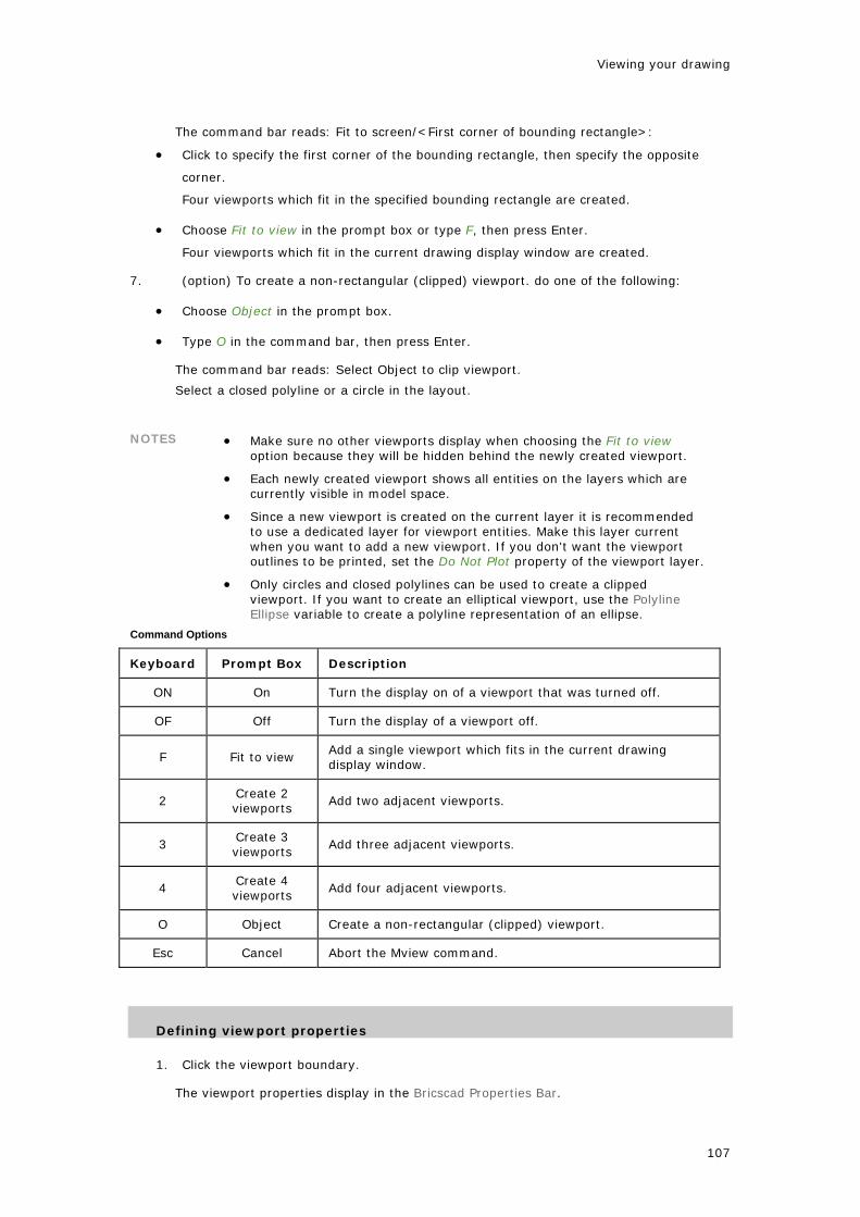
Viewing your drawing
The command bar reads: Fit to screen/<First corner of bounding rectangle>:
• Click to specify the first corner of the bounding rectangle, then specify the opposite
corner.
Four viewports which fit in the specified bounding rectangle are created.
• Choose Fit to view in the prompt box or type F, then press Enter.
Four viewports which fit in the current drawing display window are created.
7. (option) To create a non-rectangular (clipped) viewport. do one of the following:
• Choose Object in the prompt box.
• Type O in the command bar, then press Enter.
The command bar reads: Select Object to clip viewport.
Select a closed polyline or a circle in the layout.
NOTES • Make sure no other viewports display when choosing the Fit to view option because they will be hidden behind the newly created viewport.
• Each newly created viewport shows all entities on the layers which are currently visible in model space.
• Since a new viewport is created on the current layer it is recommended to use a dedicated layer for viewport entities. Make this layer current when you want to add a new viewport. If you don't want the viewport outlines to be printed, set the Do Not Plot property of the viewport layer.
• Only circles and closed polylines can be used to create a clipped viewport. If you want to create an elliptical viewport, use the Polyline Ellipse variable to create a polyline representation of an ellipse.
Command Options
Keyboard Prompt Box Description
ON On Turn the display on of a viewport that was turned off.
OF Off Turn the display of a viewport off.
F Fit to view Add a single viewport which fits in the current drawing display window.
2 Create 2 viewports
Add two adjacent viewports.
3 Create 3 viewports
Add three adjacent viewports.
4 Create 4 viewports
Add four adjacent viewports.
O Object Create a non-rectangular (clipped) viewport.
Esc Cancel Abort the Mview command.
Defining viewport properties
1. Click the viewport boundary.
The viewport properties display in the Bricscad Properties Bar.
107

Bricscad V8 - User Guide
2. Click the settings field of a property to modify.
Properties
Name Description
Center XYZ coordinates of the center point of the viewport.
To specify the center of the viewport graphically, drag the center handle of the viewport.
Height Height of the viewport in drawing units.
To specify the height of the viewport graphically, drag the top or bottom handle of the viewport.
Width Width of the viewport in drawing units.
To specify the width of the viewport graphically, drag the left or right handle of the viewport.
On Controls the display of the content of the viewport.
Clipped (not yet implemented)
Display Locks the scaling of the viewport content to preserve the scaling factor.
108

Viewing your drawing
locked
Standard scale
Lets you choose a standard scaling factor.
Custom scale Lets you define the scaling factor in a decimal format. Displays the current scaling factor.
UCS per viewport
If Yes, lets you define a UCS for this viewport.
Hide plot Controls whether the viewport boundary is plotted or not.
Navigating in a paper space layout
View manipulation commands, such as zoom, pan and view manipulation using the mouse, act slightly different in a paper space layout compared to model space (with tiled viewports).
If you are working in paper space (no viewport selected), view manipulation commands act on the complete paper space layout.
If you are working in a paper space viewport (model space with floating viewports), view manipulation commands act on the active viewport only. Except if the the display of the current paper space viewport is locked, then the view manipulation commands act on the complete paper space layout.
NOTE It is not possible to rotate the display of a paper space layout. View Rotate commands are available in viewports of which the display is not locked only.
Setting the layer visibility in a paper space viewport
1. Do one of the following:
• If Paper Space is the current workspace: double click inside the viewport to make it the
current viewport.
• If Model Space with floating viewports is the current workspace: click inside the
viewport to make it the current viewport.
2. Do one of the following.
• Click the Layers... tool button on the Settings toolbar.
• Choose Layers... in the Settings menu.
• Type explayers in the command bar, then press Enter.
The Drawing Explorer - Layers window opens.
3. In the Curr. VP (Current Viewport) column, click the layer(s) you want to freeze.
The thawed icon ( ) is replaced by the frozen icon ( ).
(option) Click the icon again to thaw a frozen layer.
4. Close the Drawing Explorer - Layers window.
5. (option) Repeat steps 1 through 4 to set the layer visibility in another paper space
viewport.
109

Bricscad V8 - User Guide
Setting the scale of a paper space viewport
1. Switch to model space (Model Space, with floating viewports).
(See Toggle between model space and paper space)
2. Click the viewport border.
The viewport properties display in the Bricscad Properties Bar.
3. Do one of the following:
• Choose a scale in the Standard scale list.
• Type a scaling factor in the Custom scale field.
The display of the viewport is scaled with respect to the layout size.
4. If necessary, adjust the viewport borders to the new scale.
5. Set the Display Locked property to Yes.
NOTE In a locked viewport it is impossible to:
• zoom or pan
• modify the scale
110

Viewing your drawing
Layouts
Layouts
In Bricscad, you can create multiple layouts for a single drawing. Each layout represents a sheet of paper. For each layout you can specify the print area, print scale, lineweight scale, pen mappings, and add viewports, dimensions, a title block, and other geometry specific to the layout. The entities you add to a layout in paper space do not appear in model space.
Each layout requires at least one layout viewport. Viewports can display all or part of the drawing’s model space entities. Each drawing can contain up to 255 layouts.
To add new layouts you can either define it yourself or your can import a layout from another drawing (template (.dwt) file, drawing (.dwg) file, or drawing interchange (.dxf) file)
Creating a new layout
1. Do one of the following:
• Click the New Layout tool button ( ) on the Layout toolbar.
• Choose Layout > New Layout in the Insert menu.
• Type layout in the command bar, press Enter, then type N and press Enter.
The command bar reads: Enter a layout name. <Layout1>:
2. Do one of the following:
• Type a unique name for the layout, then press Enter.
The name can be up to 255 characters in length and can contain letters, numbers, the
dollar sign ($), hyphen (-), and underscore (_), or any combination.
• Right click or press Enter to accept the default name (e.g. Layout1).
The new layout tab is added.
3. Create at least one viewport. (See Creating viewports in a layout for more information.)
Copying layouts
1. Right click the layout tab you want to copy.
A context menu displays.
2. Choose Copy in the context menu.
The command bar reads: Enter new layout name:
3. Type a new unique name in the command bar, then press Enter.
A copy of the selected layout is added.
Importing layouts
111

Bricscad V8 - User Guide
1. Right click the Model tab or one of the layout tabs.
A context menu displays.
2. Choose From Template... in the context menu.
The Select Template From File window opens.
3. Browse to the drawing that you want to import layouts from.
4. Click the Open button on the Select Template From File window.
The Insert Layout(s) window opens.
5. Select the layout(s) you want to import.
Press and hold the Ctrl key to select multiple layouts.
6. Click the OK button on the Insert Layout(s) window.
The selected layouts are imported.
Renaming layouts
1. Right click the layout tab you want to rename.
A context menu displays.
2. Choose Rename in the context menu.
The Rename Layout dialog opens.
3. Type a new unique name in the Name field of the Rename Layout dialog.
4. Click the OK button on the Rename Layout dialog.
Arranging layout tabs
1. Right click the layout tab you want to move.
A context menu displays.
2. Do one of the following:
• Choose Move Right.
• Choose Move Left.
3. To move the selected layout tab do one of the following:
• Select the number of tab positions.
• Choose Move to Last Layout or Move to First Layout.
112

Viewing your drawing
113
Deleting a layout
1. Right click the layout tab you want to move.
A context menu displays.
2. Choose Delete in the context menu.
The selected layout is deleted.

Drawing Entities
Entity Creation Settings
Overview
The following settings control the display and/or creation of entities.
Name Command Description
Fill mode
FILL FILLMODE
Specifies whether multilines, traces, solids, hatches (including solid-fill) and wide polylines are filled in.
Current Entity Color
CECOLOR Sets the color of new entities.
Lineweight Display LWDISPLAY Controls whether lineweights display on the screen.
Default Lineweight LWDEFAULT Defines the default lineweight.
Lineweight Units LWUNITS Defines whether lineweights are expressed in millimeters or inches.
Current Entity Lineweight
CELWEIGHT Sets the lineweight for new entities.
Current Entity Linetype Scale
CELTSCALE Sets the linetype scaling factor for new entities.
Linetype Scale LTSCALE Sets the linetype scaling factor for all entities in the drawing (global linetype scale).
Current Entity Linetype
CELTYPE Sets the linetype for new entities.
Current Layer CLAYER Sets the layer for new entities.
The current properties display in the Bricascad Properties Bar and in the Entity Properties toolbar.
Bricscad Properties Bar Entity Properties toolbar: 1. Layer 2. Color 3. Linety
114

Drawing Entities
Fill Mode
Specifies whether multilines, traces, solids, hatches (including solid-fill) and wide polylines are filled in. If Fill Mode is off, all filled entities, display and print as outlines.
You can reduce the time it takes to display or print a drawing by turning off the display of solid fill.
Polyline Donut Trace Plane (Solid)
Fill On
Fill Off
Setting Fill Mode
1. To toggle Fill Mode on / off do one of the following:
• Choose Fill in the Settings Menu.
• Click the Fill tool button ( ) on the Settings toolbar.
• Type FILL or FILLMODE in the command bar, then type T + Enter.
2. To regenerate the viewport do one of the following:
• Choose Regen in the View menu.
• Click the Regen tool button ( ) on the View toolbar.
• Type REGEN in the command bar, then press Enter.
NOTE If multiple viewports are open, click the Regen All tool button ( ) on the View toolbar to regenerate all open viewports simultaneously.
115

Bricscad V8 - User Guide
Checking the Fill Mode setting
To check whether Fill Mode is currently on or off, do one of the following:
• Type FILL or FILLMODE in the command bar.
The current status of Fill Mode is shown between arrow brackets.
• Check the Fill tool button on the Settings toolbar.
If the Fill tool button is pressed, Fill Mode is on:
If the Fill tool button is depressed, Fill Mode is off:
116

Drawing Entities
Entity Color
Entity Color
An entity's color determines how it is displayed and how it prints. Entities are created in the current color.
You can choose between 255 index colors or define a true color. Index Colors
Index color is the specification of the color of a pixel on a display screen using a an 8-bit color value, allowing up to 256 possible colors.
Each of the Index Colors has a unique number from 1 to 255. Seven of the index colors can also be referred to by name: red (1), yellow (2), green (3), cyan (4), blue (5), magenta (6) and white/black (7). Index color 7 displays white on a black screen background and black on a white screen background. Index color 7 prints in black.
The two additional color properties are BYLAYER and BYBLOCK. These color properties cause an entity to adopt the color either of the layer or of the block in which it is a member. BYLAYER is color number 256, and BYBLOCK is color number 0. In all commands where you would use a color, you can indicate BYLAYER and BYBLOCK as well as by numbers 256 and 0, respectively.
Color BYLAYER:
Entities which have a color BYLAYER adopt the color of their layer. This allows you to change the color of all such entities by adjusting the color of the layer.
Color BYBLOCK:
Entities which have a color BYBLOCK are drawn in index color 7 (black or white, depending on the screen background color). When included in a block definition, such entities adopt the color of the block.
NOTE Whether entities using an index color will be printed in this color also, depends on the Color Table (CTB) or Style Table (STB) that is used for printing. Only if the Color setting in the CTB or STB definition file is set to Use Object Color, the printed color matches the entity color.
Index color dialog
117

Bricscad V8 - User Guide
1. Colors 10 - 249
2. Colors 1 to 9
3. Colors 250 - 255
4. Current Color
5. Color Number field
6. 'Color By Block' button
7. 'Color By Layer' button
True Colors
True color is the specification of the color of a pixel on a display screen using a 24-bit value, which allows the possibility of up to 16 777 216 possible colors.
The number of bits used to define a pixel's color shade is its bit-depth. True color is sometimes known as 24-bit color. Some new color display systems offer a 32-bit color mode. The extra byte, called the alpha channel, is used for control and special effects information.
True colors use a RGB color definition (Red, Green, Blue). Each of these parameters has a range from 0 to 255. The RGB definition for black is (0,0,0), the RGB definition for white is (255,255,255).
NOTE In drawings that use Style Tables (STB) to set up plotting configurations, entities in a true color will only be printed in this color if the Color setting in the STB definition file is set to Use Object Color.
In drawings that use Color Tables (CTB) to set up plotting configurations, entities in a true color always print in this color.
True color dialog
118

Drawing Entities
1. Color Selection pane
2. Color Indicator
3. Luminosity slider
4. Current Color
5. Color Parameter fields
Setting the current entity color
1. To open the Select Color dialog, do one of the following:
• In the Color field of the Entity Properties toolbar, choose Select Color.
• Click the Select Color tool button ( ) on the Settings toolbar.
• In the Bricscad Properties Bar click Color, then choose Select Color in the drop down
list.
• Double click the Color Field in the Status Bar.
• Type SETCOLOR in the command bar.
2. (option) To select one of the index colors, do one of the following:
• Click one of the colored tiles.
• Type the color number in the Color Number field.
119

Bricscad V8 - User Guide
3. (option) To define a true color click the True Color tab on the Select Color dialog, then
do one of the following:
• Click the in Color Selection pane.
• Set the color parameters in the Color Parameter fields.
4. Click the OK button to confirm.
Choosing a named color
To set the entity color to one of the named colors, do one of the following:
• Select the color in the Color field of the Entity Properties toolbar.
• Select the color on the Color flyout of the Settings toolbar.
• In the Bricscad Properties Bar click Color, then select the color in the drop down list.
• Right click the Color Field in the Status Bar, then select the color in the context menu.
120

Drawing Entities
Lineweight
Lineweight
Lineweights determine how thick or thin entities appear on the screen and / or when printed.
The following lineweights are available: BYLAYER, BYBLOCK, DEFAULT and many additional lineweights in millimeters or inches, depending on the Lineweight Units (LWUNITS) setting..
You cannot assign lineweights to planes, points, TrueType fonts, and raster images.
New entities are drawn using the current lineweight.
Lineweight BYLAYER:
When you create an entity, it is created using the current lineweight. By default, the current lineweight for a new entity is BYLAYER. This means that the entity lineweight is determined by the current layer. When you assign BYLAYER, changing a layer’s lineweight changes the lineweight of all such entities on that layer.
Lineweight BYBLOCK:
Entities created using lineweight BYBLOCK, are drawn using the DEFAULT lineweight until include them into a block. The entities then inherit the block’s lineweight setting when you insert the block into a drawing.
DEFAULT lineweight:
The default lineweight is saved in the Default Lineweight setting (LWDEFAULT). Entities created using the default lineweight will be adjusted if the Default Lineweight setting is redefined.
NOTE For entities using an index color, lineweights will be used for printing only if the Color Table (CTB) or Plot Style (STB) is defined as 'Use object lineweight'. Otherwise the line weight is defined by the objects color or plot style.
Entities which are created in a true color always use the object line weight when printed.
Setting the current lineweight
1. (option) On the Bricscad Properties Bar, select Lineweight.
Make sure, no entity is selected.
Choose a lineweight in the drop down list.
121

Bricscad V8 - User Guide
2. (option) On the Entity Properties toolbar, click the down arrow next to the Lineweight
field, then choose a lineweight in the drop down list.
Defining the lineweight settings
1. Choose Settings in the Settings menu.
2. Select the Drawing settings category ( )
3. Expand the Display/Viewing settings sub-category.
4. Expand the Lineweights settings group.
122

Drawing Entities
5. (option) Select the Default Lineweight setting (LWDEFAULT), then select a lineweight in
the drop down list.
6. (option) Select the Lineweight Display setting (LWDISPLAY), then click the checkbox to
toggle the display of lineweights.
7. (option) Select the Lineweight Units setting (LWUNITS), then choose Millimeters or
Inches.
8. Close the Settings dialog.
NOTE You can toggle the display of lineweights on/off in the Status Bar also.
123

Bricscad V8 - User Guide
Linetype
Entity Linetype
You use different linetypes to differentiate the purpose of one line from another. A linetype consists of a repeating pattern of dots, dashes, or blank spaces. Linetypes determine the appearance of entities both on the screen and when printed. By default, every drawing has at least three linetypes: CONTINUOUS, BYLAYER and BYBLOCK. Your drawing may also contain an unlimited number of additional linetypes. Linetype definitions are saved in the drawing. New linetypes are either imported from other drawings or loaded from a linetype file (e.g. iso.lin or default.lin).
New entities are drawn using the current lineweight.
Linetype BYLAYER:
Entities which have a linetype BYLAYER adopt the linetype of their layer. This allows you to change the linetype of all such entities by adjusting the linetype of the layer.
Linetype BYBLOCK:
Entities created using linetype BYBLOCK, are drawn as continuous lines until you include them into a block. The entities then inherit the block’s linetype setting when you insert the block into a drawing.
Linetype SCALE
Non-continuous linetypes consist of lines, gaps and dots put together in a variety of patterns. In complex linetypes also text or shapes can be included. In the linetype definition the length of the lines and gaps are defined in drawing units. To display the linetype correctly it needs to be scaled to match the dimensions of your drawing. The linetype scaling factor is defined by the Linetype Scale setting (LTSCALE). Bricscad will always put a dash at the start and end of a line, polyline, arc or spline. The linetype pattern is also nicely centered, so that both ends of the entity look the same.
Because linetypes are affected by scale, paper space becomes a problem. A linetype scale that looks fine in model space is possibly going to look wrong in paper space. This problem is solved by the Paperspace Linetype Scale setting (PSLTSCALE). When set to 0 or Off, PSLTSCALE scales linetypes the same in model space and in layouts, when set to 1or On, linetypes in layouts are drawn to the same scale as the viewport's scale.
Linetypes are normally generated from vertex to vertex. Polylines of which the vertices are very close together might be rendered as a continuous line, if the linetype pattern does not fit between two subsequent vertices. The Polyline Generation setting (PLINEGEN) solves this problem: when set to 1, the linetype is drawn from one end of the polyline to the other end, instead of from vertex to vertex.
The same polyline drawn with PLINEGEN on (left) and off (right).
Go to top
124

Drawing Entities
Setting the current linetype
1. (option) On the Bricscad Properties Bar, select Linetype.
Make sure, no entity is selected.
Choose a linetype in the drop down list.
2. (option) On the Entity Properties toolbar, click the down arrow next to the Linetype
field, then choose a linetype in the drop down list.
3. (option) Right click on the Linetype field in the Status Bar, then choose a linetype in the
context menu.
Go to top
Adding a new linetype
1. On the Bricscad Properties Bar, select Linetype.
Make sure, no entity is selected.
2. Choose Load... in the drop down list.
125
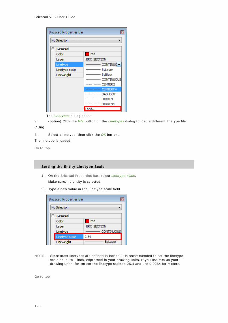
Bricscad V8 - User Guide
The Linetypes dialog opens.
3. (option) Click the File button on the Linetypes dialog to load a different linetype file
(*.lin).
4. Select a linetype, then click the OK button.
The linetype is loaded.
Go to top
Setting the Entity Linetype Scale
1. On the Bricscad Properties Bar, select Linetype scale.
Make sure, no entity is selected.
2. Type a new value in the Linetype scale field..
NOTE Since most linetypes are defined in inches, it is recommended to set the linetype scale equal to 1 inch, expressed in your drawing units. If you use mm as your drawing units, for cm set the linetype scale to 25.4 and use 0.0254 for meters.
Go to top
126

Drawing Entities
Setting the Global Linetype Scale
1. Choose Settings in the Settings menu.
2. Select the Drawing settings category ( )
3. Expand the Entity Creation settings sub-category.
4. Select the Global Linetype Scale setting (LTSCALE).
5. Type a new value in the Global Linetype Scale field, then press Enter.
The drawing is regenerated.
6. Close the Settings dialog.
NOTE The Global Linetype Scale must be set with respect to the plot scale. E.g. if you want to plot your drawing at 1/50, set the LTSCALE setting to 50. Remember to set the Paperspace Linetype Scale setting (PSLTSCALE) Off if you want linetypes to be scaled equally in model space and paper space.
Go to top
127

Bricscad V8 - User Guide
Current Layer
When you create new entities, they are drawn on the current layer. To draw new entities on a different layer, you must first make that layer the current layer.
Setting the current layer
1. (option) On the Bricscad Properties Bar, select Layer.
Make sure, no entity is selected.
Choose a layer in the drop down list.
2. (option) On the Entity Properties toolbar, click the down arrow next to the Layer field,
then choose a layer in the drop down list.
3. (option) Right click on the Layer field in the Status Bar, then choose a layer in the
context menu.
128
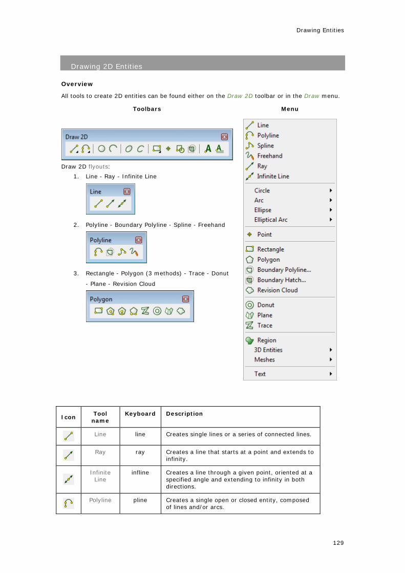
Drawing Entities
Drawing 2D Entities
Overview
All tools to create 2D entities can be found either on the Draw 2D toolbar or in the Draw menu.
Toolbars Menu
Draw 2D flyouts:
1. Line - Ray - Infinite Line
2. Polyline - Boundary Polyline - Spline - Freehand
3. Rectangle - Polygon (3 methods) - Trace - Donut
- Plane - Revision Cloud
Icon Tool
name Keyboard Description
Line line Creates single lines or a series of connected lines.
Ray ray Creates a line that starts at a point and extends to
infinity.
Infinite Line
infline Creates a line through a given point, oriented at a specified angle and extending to infinity in both directions.
Polyline pline Creates a single open or closed entity, composed
of lines and/or arcs.
129

Bricscad V8 - User Guide
Boundary Polyline
bpoly boundary
Calculates a closed polyline from a boundary set.
Spline spline Creates open or closed curved lines.
Freehand freehand Creates lines as if you were sketching, using a
pencil.
Circle circle Creates circles.
Arc arc Creates circular arcs.
Ellipse ellipse Creates ellipses
Elliptical
Arc
ellipse Creates elliptical arcs
Rectangle rectangle Creates Rectangles
Polygon polygon Creates equal sided polygons.
Trace trace Creates traces.
Donut donut Creates donuts.
Plane plane Creates planes (solids).
Revision Cloud
revcloud Creates revisioun clouds.
Point point Creates points.
130

Drawing Entities
Lines
A line consists of two points: a start point and an endpoint. Using the Line command you can draw a series of connected lines, but each line is considered a separate line entity.
Drawing lines
1. Do one of the following
• Click the Line tool button ( ) on the Draw 2D toolbar.
• Choose Line in the Draw menu.
• Type line in the command bar, then press Enter.
• Type L in the command bar, then press Enter.
The command bar reads: ENTER to use last point/Follow/<Start of line>:
A prompt box opens:
2. Specify the start point.
The line displays dynamically.
3. Specify the end point.
The line is drawn and the following line displays dynamically starting in the endpoint of the first
line.
• Using Ortho Mode or Polar Tracking you can type the length of the line in the command
bar.
• Using Snap Tracking you can position the end point with respect to the start point and
any existing point in the drawing.
The prompt box changes:
4. (option) Repeat step 3 to draw a series of connected lines.
When the second line is drawn, the options in the prompt box are:
After the third line, the options in the prompt box are:
131

Bricscad V8 - User Guide
4. Right click to stop drawing lines.
5. (option) Right click to restart.
Command Options
Keyboard Prompt
Box Description
Enter The last point used in a previous drawing tool is used as the start point of the line.
Concludes the Line command.
F Follow The line is created as an extension of the previously drawn entity. If this was an arc, the line is drawn tangent to the arc, starting at the endpoint of the arc.
A Angle Type the angle for the next line. Positive angles are measured counter clockwise from the positive x-axis. The Length option follows by default.
L Length Type the length for the next line.
C Close Connects the end point of the last line to the start point of the first line and concludes the Line command.
U Undo Undoes the previous action.
D Done Concludes the Line command.
132

Drawing Entities
Rays
A ray is a line that starts at a point and extends to infinity. Because rays extend to infinity, they are not calculated as part of the drawing extents. The default method for drawing a ray is to select the start point of the ray, and then specify its direction.
Rays and Infinite Lines or sometimes referred to as construction lines.
Drawing rays
1. Do one of the following:
• Click the Ray tool button ( ) on the Draw 2D toolbar.
• Choose Ray in the Draw menu.
• Type ray in the command bar, then press Enter.
The command bar reads: Infinite ray: Bisect/Horizontal/Vertical/Angle/Parallel/<Start of Ray>:
A prompt box opens:
2. Specify the start point of the ray.
The ray displays dynamically.
3. Specify the direction of the ray.
The next ray displays dynamically.
4. (option) Keep specifying directions to draw a series of rays, starting from the same
point.
5. Right click to stop drawing rays.
Command Options
Keyboard Prompt
Box Description
H Horizontal The ray is drawn parallel to the x-axis of the current coordinate system.
V Vertical The ray is drawn parallel to the y-axis of the current coordinate system.
A Angle
The ray is drawn at the specified angle. You can define the angle in one of two ways:
• type the angle in the command bar
• define the angle by clicking two points in the drawing
133

Bricscad V8 - User Guide
B Bisect
The ray is drawn perpendicular to an existing entity. The startpoint of the ray is the midpoint of the selected entity. You are prompted to choose the side of the selected entity where the ray must be created.
P Parallel The ray is drawn parallel to an existing entity. You are prompted to create the ray at a specified distance and side of the existing entity or to draw the ray through a point.
C Cancel Concludes the command.
134

Drawing Entities
Infinite Lines
An infinite line is a line through a given point, oriented at a specified angle and extending to infinity in both directions. Because infinite lines extend to infinity, they are not calculated as part of the drawing extents. The default method for drawing an infinite line is to select a point and then specify its direction.
Rays and Infinite Lines or sometimes referred to as construction lines.
Drawing infinite lines
1. Do one of the following:
• Click the Infinite Line tool button ( ) on the Draw 2D toolbar.
• Choose Infinite Line in the Draw menu.
• Type infline in the command bar, then press Enter.
The command bar reads: Infinite line: Bisect/Horizontal/Vertical/Angle/Parallel/<Start of Ray>:
A prompt box opens:
2. Specify the start point of the infinite line.
The infinite line displays dynamically.
3. Specify the direction of the infinite line.
The next infinite line displays dynamically.
4. (option) Keep specifying directions to draw a series of infinite lines, starting from the
same point.
5. Right click to stop drawing infinite lines.
6. (option) Right click to restart.
Command Options
Keyboard Prompt
Box Description
H Horizontal The infinite line is drawn parallel to the x-axis of the current coordinate system.
V Vertical The infinite line is drawn parallel to the y-axis of the current coordinate system.
A Angle The infinite line is drawn at the specified angle. You can define the angle in one of two ways:
135

Bricscad V8 - User Guide
• type the angle in the command bar
• define the angle by clicking two points in the drawing
B Bisect
The infinite line is drawn perpendicular to an existing entity. The start point of the infinite line is the midpoint of the selected entity. You are prompted to choose the side of the selected entity where the infinite line must be created.
P Parallel
The infinite line is drawn parallel to an existing entity. You are prompted to create the infinite line at a specified distance and side of the existing entity or to draw the infinite line through a point.
C Cancel Concludes the command.
136

Drawing Entities
Polylines
Polylines
A polyline is an open or closed sequence of connected line and arc segments, which are treated as a single entity. Each segment of a polyline can have a width that is either constant or tapers over the length of the segment. When a polyline is edited, you can modify the entire polyline or change individual segments.
zero width polyline constant width polyline
tapered width polyline
NOTE When Fill Mode is turned off, all filled entities, such as wide polylines and planes, display and print as outlines.
Drawing polylines
1. Do one of the following
• Click the Polyline tool button ( ) on the Draw 2D toolbar.
• Choose Polyline in the Draw menu.
• Type pline in the command bar, then press Enter.
• Type PL in the command bar, then press Enter.
The command bar reads: ENTER to use last point/Follow/<Start of polyline>:
A prompt box opens:
137

Bricscad V8 - User Guide
2. Specify the start point of the polyline.
The prompt box changes:
3. Specify the second point of the polyline.
The prompt box changes:
4. (option) Repeat step 3 to add more straight segments.
5. (option) Do one of the following to start drawing arc segments:
• Type A, then press Enter.
• Choose Draw arcs in the prompt box.
The prompt box changes:
An arc segement displays dynamically. The arc is tangent to the previous line segment.
6. Specify the endpoint of the arc.
7. (option) Repeat step 6 to add more arc segments.
8. (option) Do one of the following to start drawing line segments:
• Type L, then press Enter.
• Choose Draw lines in the prompt box.
138

Drawing Entities
8. Specify the endpoint of the line segment.
9. Right click or choose Done in the prompt box to stop.
10. (option) Right click to restart.
Command Options
Keyboard Prompt
Box Description
Enter The last point used in a previous drawing tool is used as the start point of the first segment.
Concludes the command.
A Draw arcs
When drawing lines, start drawing arc segments.
A Angle When drawing arcs, specify the angle for the arc segment.
You are then prompted to specify either the Endpoint, Center or Radius of the arc (*).
C Close When drawing lines, closes the polyline.
CL Close When drawing arcs, closes the polyline.
CE Center When drawing arcs, specify the center point of the arc segment.
You are then prompted to specify either the Angle, Length or endpoint of the arc (*).
D Distance When drawing lines, specify the length of the next segment.
The Angle option follows by default.
D Direction
When drawing arcs, specify the direction for a straight segment.
You are prompted to specify the endpoint of the arc.
This option allows you to draw line segments when drawing arcs if the endpoint of the arc lies in the specified direction.
F Follow The segment is created as an extension of the previously drawn entity or segment. If this was an arc, the segment is drawn tangent to the arc, starting at the endpoint of the arc.
H Half
width
Specify a new current width for polyline segments. The width will be twice the keyboard entry, expressed in drawing units.
You are prompted to specify the start width first, then the end width. The current width shows between arrow brackets. To accept the current width, press Enter. By default the end with equals the start width.
L Draw lines
When drawing arcs, start drawing line segments.
W Width
Specify a new current width for polyline segments. The width equals the keyboard entry, expressed in drawing units.
You are prompted to specify the start width first, then the end width. The current width shows between arrow brackets. To accept the current width, press Enter. By default the end with equals the start width.
R Radius
When drawing arcs, specify the radius of the arc segment.
You are prompted to specify the Angle (*) or the endpoint of the arc. If you have chosen to specify the angle, you are prompted to specify the direction of the chord.
139

Bricscad V8 - User Guide
S Second point
When drawing arcs, draws the arc segment through the specified point. This point is NOT a vertex of the polyline.
U Undo Removes the last segment.
D Done Concludes the command.
(*) Type the capitalized letter, followed by Enter to choose an option.
Creating boundary polylines
1. Do one of the following
• Click the Boundary Polyline tool button ( ) on the Draw 2D toolbar.
• Choose Boundary Polyline in the Draw menu.
• Type bpoly in the command bar, then press Enter.
The Boundary dialog box opens.
2. (option) Click the New Boundary Set button ( )
The Boundary dialog closes.
Select the boundary entities in the drawing, then Press Enter.
The Boundary dialog opens.
140

Drawing Entities
3. Click the Pick points in boundaries ( ) button on the Boundary dialog box.
The dialog box closes.
4. Click in the area where you want to create the boundary polyline: point 1 in the image
below.
5. The boundary polyline displays in dashed lines.
6. (option) Keep picking points to create more boundary polylines.
7. Right click to accept the polyline(s).
The Boundary dialog box opens again.
8. Click the OK button on the Boundary dialog box.
The polyline(s) is (are) created.
NOTES • If you select the boundary entities before launching the Boundary Polyline tool, you can make the selection set active by pressing the New
Boundary Set button ( ) in step 2.
• If you type -boundary (don't forget the "minus" sign) in the command bar, you are prompted to click the area where you want to create the polyline(s) immediately (no dialog opens) then right click to create the polyline(s).
141

Bricscad V8 - User Guide
Splines
A spline is an open or closed smooth curve defined by a set of points. You can use splines to draw curved shapes, which cannot be drawn as a polyline.
Drawing splines
1. Do one of the following
• Click the Spline tool button ( ) on the Draw 2D toolbar.
• Choose Spline in the Draw menu.
• Type spline in the command bar, then press Enter.
The command bar reads: First point of spline:
2. Specify the first point of the spline.
3. Define the second point of the spline.
The command bar reads: Close/Fit Tolerance/<next point>:
A prompt box displays.
4. (option) Repeat step 3 to define more points.
5. Right click to stop adding more points.
The command bar reads: Select starting tangent point:
A line that is tangent to the spline displays dynamically from the start point of the spline.
6. Click to define the curve of the spline.
The command bar reads: Select ending tangent point:
142

Drawing Entities
A line that is tangent to the spline displays dynamically from the start end of the spline.
7. Click to conclude the spline command.
8. (option) Right click to restart.
NOTE The red dashed lines in the above images represent the polyline through the control points of the spline.
Command Options
Keyboard Prompt
Box Description
C Close Create a closed spline. In this case the spline command concludes after defining the starting tangent point.
F Fit
Tolerance
By default, the spline passes through all of the control points. When you draw a spline, you can change this by specifying the fit tolerance. The fit tolerance value determines how closely the spline fits the set of points you specify. For example, a spline fit tolerance value of 0 (zero) causes the spline to pass through the control points. A value of 0.01 creates a spline that passes through the start and endpoints and within 0.01 units of the intermediate control points.
Cancel Ends the spline command without creating the spline.
143

Bricscad V8 - User Guide
Freehand
A freehand sketch consists of a series of straight line segments, created either as individual line entities or as a polyline. Before you begin creating a freehand sketch, you must set the length, or increment, of each segment. The smaller the segments, the more accurate your sketch, but small segments increase the file size.
After you specify the length of the sketch segments, the crosshairs change to a Pencil tool. A freehand sketch line is not added to the drawing until you "write" the sketch into your drawing.
Whether a chain of individual lines or a polyline is created by the Freehand tool is controlled through the Sketch Poly (skpoly) setting. When the skpoly setting is On the Freehand tool creates polylines.
Creating a freehand sketch
1. Do one of the following
• Click the Freehand tool button ( ) on the Draw 2D toolbar.
• Choose Freehand in the Draw menu.
• Type freehand in the command bar, then press Enter.
The command bar reads: Freehand: Length of segments <current length>:
2. Do one of the following to define the length of the segments::
• Press Enter to accept the current length.
• Type a new value in the command bar.
• Define the length graphically by clicking two points.
The new value is saved in the SKETCHINC setting.
3. Click to start sketching (pen down). The crosshairs change to into the Pencil tool ( )
The command bar reads: Press ENTER to end /Pen up/Quit/Delete on /Connect /Straight to
cursor /Write to drawing /(Sketching ...):
A prompt box displays:
4. Move the cursor to sketch.
The sketched line displays in light green.
5. (option) Click to stop sketching (pen up), then click again (pen down) to resume.
144

Drawing Entities
6. Right click to create the freehand sketch.
Command Options
Keyboard Prompt
Box Description
D Delete on/off
Toggle between the Pencil tool ( ) and the Erase tool ( ).
When the Erase tool is active, move the cursor over the freehand sketch line to erase segments. Because the Erase tool cannot break a freehand sketch line, always begin at the start or end segment of the freehand sketch line to erase.
C Connect to end
After erasing segments, move the cursor to the last segment to continue.
W Write, then
resume
Create the freehand sketch line(s) drawn so far, then continue the Freehand command.
P Toggles between pen up (move cursor without drawing) and pen down (draw segments).
S Straight to cursor: connect the endpoint of the last segment to the current cursor position when pen is up.
Enter Done Create the freehand sketch line(s) and conclude the Freehand tool.
145

Bricscad V8 - User Guide
Circles
Circles
The default method for drawing a circle is to specify a center point and radius.
Other methods to draw circles can be found in the Circle submenu of the Draw menu.
General procedure to draw a circle
1. Do one of the following.
• Click the Circle tool button ( ) on the Draw 2D toolbar.
• Type circle in the command bar, then press Enter.
• Type C in the command bar, then press Enter.
The command bar reads: 2Point/3Point/RadTanTan/Arc/Multiple/<Center of circle>:
A prompt box displays:
2. Specify the center point of the circle.
The command bar reads: Diameter/<Radius> <current radius>:
The prompt box changes:
3. Do one of the following:
• Press Enter to accept the current radius.
• Type a new radius and press Enter.
• Click to define the radius graphically.
Command Options
146

Drawing Entities
Keyboard Prompt Box Description
2P 2_Point Draw a circle by defining the diameter by two points.
3P 3-Point Draw a circle by specifying three points.
RTT Radius-Tangent-
Tangent
Draw a circle tangent to two entities and a specified radius. You can draw circles tangent to lines, polyline segments, arcs and circles.
A Turn_arc_into_circle Turn an arc into a circle.
M Multiple_Circles Create multiple circles of the same size.
D Diameter Draw a circle by specifying the center point and diameter.
Esc Cancel Abort the Circle command.
Editing a circle
1. Select the circle.
The properties of the circle display in the Bricscad Properties bar.
2. Type a new value in the Center, Radius, Diameter, Circumference or Area field, then
press Enter.
3. Press the Esc key to stop editing the circle.
147

Bricscad V8 - User Guide
Arcs
Arcs
The default method for drawing circular arcs is to specify three points: the start point, a second point and the endpoint.
Other methods to draw arcs can be found in the Arc submenu of the Draw menu.
General procedure to draw an arc
1. Do one of the following.
• Click the Arc tool button ( ) on the Draw 2D toolbar.
• Type arc in the command bar, then press Enter.
• Type A in the command bar, then press Enter.
The command bar reads: Enter to use last point/Center/Follow/<Start of arc>:
A prompt box displays:
2. Specify the start point of the arc.
The command bar reads: Angle/Center/Direction/End/Radius/<Second point>:
148

Drawing Entities
The prompt box changes:
3. Specify the second point of the arc.
The command bar reads: End point:
4. Specify the end point of the arc.
Command Options
Keyboard Prompt
Box Description
C Center
Draw an arc by first specifying the center point, then the start point, then you can choose between specifying:
• endpoint (default)
• the included angle (option)
• the length of the chord (option)
F Follow Draw an arc tangent to the previously drawn line or polyline segment. The arc start at the endpoint of the line or polyline segment.
Esc Cancel Abort the Arc tool.
The following options are available after specifying the start point of the arc first:
A Angle
Specify the included angle, then you can choose between specifying:
• the endpoint (default)
• the center point (option)
C Center
Specify the center point, then you can choose between specifying:
• the endpoint (default)
• the included angle (option)
• the length of the chord (option)
149

Bricscad V8 - User Guide
D Direction Define the direction of tangent in the start point of the arc, then define the endpoint.
E End
Define the end point of the arc, then you can choose between specifying:
• center point (default)
• the included angle (option)
• the direction of the tangent in the start point of the arc (option)
• the radius (option)
R Radius
Define the radius, then you can choose between specifying:
• the endpoint (default)
• the included angle (option)
Esc Cancel Abort the Arc tool.
Editing an arc
1. Select the arc.
The properties of the arc display in the Bricscad Properties bar.
2. Type a new value in the Center, Radius, Start angle or End angle, then press Enter.
3. Press the Esc key to stop editing the arc.
150

Drawing Entities
Ellipses
Ellipses
The default method for drawing an ellipse is to specify the endpoints of one axis of the ellipse and then specify a distance representing half the length of the second axis. The endpoints of the first axis determine the orientation of the ellipse. The longer axis of the ellipse is called the major axis, and the shorter one is the minor axis. The order in which you define the axes does not matter. The program determines the major and minor axes based on their relative lengths. Half the major axis is called the major radius, half the minor axis is the minor radius. The ratio (minor radius divided by the major radius) defines the eccentricity of the ellipse. A circle is an ellipse with an eccentricity of 1.
Other methods to draw ellipses can be found in the Ellipse submenu of the Draw menu.
The Polyline Ellipse variable: controls whether real ellipses or a polyline representation is created.
If the variable is ON, the Ellipse tool creates a closed polyline, if the variable is OFF real ellipses are created.
The difference between a real ellipse and a polyline representation of an ellipse is visible when you select the ellipse. A real ellipse has five handles: center point and the endpoints of the axes. A polyline representation of an ellipse is a closed polyline composed of arc segments.
real ellipse (left) and the polyline representation of an ellipse (right)
NOTE Since ellipses cannot be used as a clip boundary for external references or to create clipped paperspace viewports, you must use a polyline representation to do these jobs.
Setting the Polyline Ellipse variable
Do one of the following:
• In the command bar type pellipse, then press Enter.
• In the Settings dialog, go to Drawing > Drafting > Entity Creation > Other entities.
151

Bricscad V8 - User Guide
General procedure to draw an ellipse
1. Do one of the following.
• Click the Ellipse tool button ( ) on the Draw 2D toolbar.
• Type ellipse in the command bar, then press Enter.
• Type EL in the command bar, then press Enter.
The command bar reads: Arc/Center/<First end of ellipse axis>:
A prompt box displays:
2. Specify the the first end of the ellipse axis.
The command bar reads: Second end of axis:
3. Specify the second end of the ellipse axis.
The command bar reads: Rotations/<Other axis>:
A prompt box displays:
4. Specify the length of half the other axis of the ellipse.
Command Options
Keyboard Prompt
Box Description
A Arc Creates an elliptical arc.
C Center First specify the center point of the ellipse, then specify the endpoint of the first axis and the length of half the second axis.
R Rotation Specify the rotation around the first axis.
Esc Cancel Abort the Ellipse command.
NOTE If the Polyline Ellipse variable is off, the Arc option is not available.
152

Drawing Entities
Editing an ellipse
1. Select the ellipse.
The properties of the ellipse display in the Bricscad Properties bar.
2. Type a new value in the Center, Major radius, Minor radius, Radius ratio, Start angle
or End angle field, then press Enter.
3. Press the Esc key to stop editing the ellipse.
153

Bricscad V8 - User Guide
Elliptical Arcs
Elliptical Arcs
An elliptical arc is a portion of an ellipse. The default method for drawing an elliptical arc is to specify the endpoints of one axis of the ellipse, and then specify a distance representing half the length of the second axis. Then you specify the start and end angles for the arc, measured from the center of the ellipse in relation to its major axis.
Other methods to draw elliptical arcs can be found in the Ellipse submenu of the Draw menu.
General procedure to draw an elliptical arc
1. Do one of the following.
• Click the Elliptical Arc tool button ( ) on the Draw 2D toolbar.
• Launch the Ellipse command using the Arc option.
The command bar reads: Center/<First end of ellipse axis>:
A prompt box displays:
2. Specify the first end or the ellipse axis.
The command bar reads: Second end of axis:
3. Specify the second end of the ellipse axis.
The command bar reads: Rotation/<Other axis>
A prompt box displays:
4. Specify the length of half the other axis of the ellipse.
The command bar reads: Parameter/<Start angle of arc>:
The prompt box changes:
5. Specify the start angle of the elliptical arc.
The elliptical arc is drawn dynamically when you move the crosshairs.
The command bar reads: Parameter/Included/<End angle>:
154

Drawing Entities
The prompt box changes:
6. Specify the end angle of the elliptical arc.
Command Options
Keyboard Prompt
Box Description
C Center First specify the center point of the ellipse, then specify the endpoint of the first axis and the length of half the second axis.
R Rotation Specify the rotation around the first axis.
P Parameter
Draw an elliptical arc by specifying its parametric vector equation.
The equation is:p(u) = c + a * cos(u) = b * sin(u)
c = the center of the ellipse; a = major axis; b = minor axis
I Included angle
Angle between the radius vector of the start point and the radius vector of the end point of the elliptical arc.
Esc Cancel Abort the Elliptical Arc tool.
Editing an elliptical arc
1. Select the elliptical arc.
The properties of the elliptical arc display in the Bricscad Properties bar.
2. Type a new value in the Center, Major radius, Minor radius, Radius ratio, Start angle
or End angle field, then press Enter.
3. Press the Esc key to stop editing the elliptical arc.
155

Bricscad V8 - User Guide
Rectangles
A rectangle is created as a closed, four sided polyline. A rectangle is drawn by specifying two opposite corners. Unless the Rotated option is chosen, the sides of a rectangle are always parallel to the x-axis and y-axis of the current coordinate system.
Drawing rectangles
1. Do one of the following
• Click the Rectangle tool button ( ) on the Draw 2D toolbar.
• Choose Rectangle in the Draw menu.
• Type rectangle in the command bar, then press Enter.
• Type rec in the command bar, then press Enter.
The command bar reads: Chamfer/Elevation/Fillet/Rotated/Square/Thickness/Width/<select first corner of rectangle>:
A prompt box opens:
2. Specify the first corner of the rectangle.
The rectangle displays dynamically when you move the cursor.
3. Specify the opposite corner of the rectangle.
The rectangle is created.
4. (option) Right click to draw more rectangles.
NOTE Because a rectangle is created as a closed polyline, rectangles have a direction. The direction of a closed polyline is positive if it is drawn counter-clockwise and negative if it is drawn in a clockwise direction. Rectangles have a counter-clockwise direction if both the X- and Y-coordinate of the second point are higher or lower than the coordinates of the first point (= movement of the cursor is positive or negative along X- and Y-axis). Rectangles have a clock-wise direction if the X- or Y-coordinate is higher or lower than the X- or Y-coordinate of the first point (= movement of the cursor is positive along the X-axis and negative along the Y-axis or vice versa).
The Reverse Direction option of the Edit Polyline tool changes the direction of a polyline.
Command Options
Keyboard Prompt Description
156

Drawing Entities
Box
C Chamfer Draw a rectangle of which the corners are equally chamfered. You are prompted to specify the chamfer distances.
F Fillet Draw a rectangle of which the corners are equally filleted. You are prompted to specify the fillet radius.
R Rotated
Draw a rotated rectangle. When the second corner is specified, you are prompted to type the rotation angle in the command bar or define the angle graphically.
S Square Draw a square. Use Ortho Mode to draw the square parallel to the x-axis.
Squares can also be drawn as a four-sided polygon.
E Elevation
Draw a rectangle at the specified Elevation. All rectangles created in the current session of the drawing will be drawn with an offset from the xy-plane, until you define the Elevation differently.
T Thickness Define the Thickness for the rectangle polyline
W Width of line
Define the Width for the four segments of the rectangle polyline.
Esc Cancel Abort the Rectangle command.
Rectangles: Elevation = 0 (left), Thickness = 50 (middle), Elevation = 50 (right)
NOTE When Fill Mode is turned off, all filled entities, such as wide polylines and planes, display and print as outlines.
157

Bricscad V8 - User Guide
Polygons
Polygons are closed polylines comprised of a minimum of three and a maximum of 1,024 equal-length sides.
In Bricscad you can draw polygons using the following methods:
• Centre - Vertex: first define the center point, then the vertex (= radius of the circumscribed circle method).
• Center - Side: first define the center point, then the midpoint of a side (= radius of the inscribed circle method).
• Edge: define the length of the side of the polygon.
Drawing polygons
1. Do one of the following
• Click the Polygon, Center - Vertex tool button ( ) on the Rectangle flyout of Draw 2D
toolbar.
• Choose Polygon in the Draw menu.
• Type polygon in the command bar, then press Enter.
The command bar reads: Polygon: Multiple/Width of line/<Number of sides> <4>:
A prompt box opens:
2. Specify the number of sides, then press Enter.
The command bar reads: Specify by: Edge/<Center of polygon>:
The prompt box changes:
3. Specify the center of the polygon.
The command bar reads: Specify by: Side/<Select vertex point>:
the prompt box changes:
4. Specify a vertex point of the polygon.
The polygon is created.
Command Options
158

Drawing Entities
Keyboard Prompt
Box Description
W Width of line
Define the Width for the all segments of the polygon.
M Multiple polygons
Draw multiple identical polygons. When the polygon is created you are prompted to define the midpoints of the other polygons. This option is not available using the Edge method.
E Specify by edge
Use the Edge method.
V Specify by vertex
Use the Center - Vertex method.
S Specify by side
Use the Center - Side method.
Esc Cancel Abort the Polygon command.
NOTE When Fill Mode is turned off, all filled entities, such as wide polylines and planes, display and print as outlines.
159

Bricscad V8 - User Guide
Traces
Traces are 4-sided filled entities, created with two parallel sides. When you create a series of traces, they are L-connected to each other.
Drawing traces
1. Do one of the following
• Click the Trace tool button ( ) on the Rectangle flyout of the Draw 2D toolbar.
• Choose Trace in the Draw menu.
• Type trace in the command bar, then press Enter.
The command bar reads: Width of trace <current width>:
2. Do one of the following:
• Right click to accept the current width.
• Type a new current width in the command bar.
• Define a new current width graphically by clicking two points.
The command bar reads: Start of trace:
3. Specify the start point of the trace.
The command bar reads: Next point:
4. Specify the end point of the first trace.
A line indicates the direction of the first trace. The direction of the second trace displays
dynamically.
5. Do one of the following:
• Right click to create the trace.
• Specify the endpoint of the next trace.
6. (option) Repeat step 5 to keep adding traces.
NOTE When Fill Mode is turned off, all filled entities, such as traces, display and print as outlines.
160

Drawing Entities
Donuts
Donuts are solid, filled circles or rings created as closed, 2-segment, wide polylines. The default method to draw donuts is to specify its inside and outside diameters, and then specify its center. If the inside diameter is zero, a filled circle is created.
Drawing donuts
1. Do one of the following:
• Click the Donut tool button ( ) on the Rectangle flyout of Draw 2D toolbar.
• Choose Donut in the Draw menu.
• Type donut in the command bar, then press Enter.
The command bar reads: 2Point/3Point/RadTanTan/<Inside diameter of donut> <current inside diameter>:
A prompt box opens:
2. Do one of the following:
• Right click to accept the current inside diameter.
• Type a new inside diameter in the command bar.
• Define a new inside diameter graphically by clicking two points.
The command bar reads: Outside diameter of donut <current outside diameter>:
3. Do one of the following:
• Right click to accept the current outside diameter.
• Type a new outside diameter in the command bar.
• Define a new outside diameter graphically by clicking two points.
The command bar reads: Center of donut:
4. Specify the center of the donut.
The donut is created.
5. (option) Specify the center point of another donut.
6. Right click to conclude the donut command.
161

Bricscad V8 - User Guide
Command Options
Keyboard Prompt Box Description
2P 2 point Draw a donut by specifying the width and outside diameter
3P 3 point Draw a donut by first specifying the width, then you are prompted to specify three points on the outside of the donut.
RTT Radius
Tangent Tangent
Draw a donut tangent to 2 circles or circular arcs. You are prompted to specify the width and outside diameter of the donut.
NOTE When Fill Mode is turned off, all filled entities, such as wide polylines and planes, display and print as outlines.
162

Drawing Entities
Planes
Planes are rectangular, square, triangular or quadrilateral areas filled with a solid color. Planes in Bricscad are similar to Solids in Autocad®.
Left to right: quadrilateral, rectangular, square and triangular planes
Drawing planes
1. Do one of the following:
• Click the Plane tool button ( ) on the Rectangle flyout of Draw 2D toolbar.
• Choose Plane in the Draw menu.
• Type plane in the command bar, then press Enter.
The command bar reads: Rectangle/Square/Triangle/<First point of plane>:
A prompt box opens:
2. Specify the first point of the plane.
3. Specify the second point of the plane.
4. Specify the third and fourth point of the plane.
The plane is created.
5. (option) Repeat step 4 to add more planes.
A series of connected planes is created.
6. Right click to conclude.
Command Options
Keyboard Prompt
Box Description
R Rectangle
Draw a rectangular plane. You are prompted to specify two opposite corners of the plane and a rotation angle (much like in the Rotated option of the Rectangle command). You can create a series of connected rectangular planes.
163

Bricscad V8 - User Guide
S Square
Draw a square plane. You are prompted to specify two subsequent corners of the square (much like the Square option of the Rectangle command). You can create a series of connected square planes.
T Triangle Draw a equal sided triangular plane. You are prompted to specify to corners of the triangle. You can create a series of connected triangular planes.
NOTE When Fill Mode is turned off, all filled entities, such as wide polylines and planes, display and print as outlines.
164

Drawing Entities
Revision Clouds
A revision cloud is an open or closed polyline composed of arcs. Revisions clouds are used to for reviewing or redlining purposes to indicate the parts of the drawing that need to be adjusted or annotated.
Before you start drawing revision clouds, first define the Arc length and Style.
Drawing revision clouds
1. Do one of the following:
• Click the Revision Cloud tool button ( ) on the Rectangle flyout of Draw 2D toolbar.
• Choose Revision Cloud in the Draw menu.
• Type revision cloud in the command bar, then press Enter.
The command bar reads: Specify start point or [Arc length/Object/Style] <Object>:
A prompt box opens:
2. (option) To define the Arc length, do one of the following:
• Choose Arc length in the prompt box.
• Type A in the command bar, then press Enter.
The command bar reads: Specify minimum length of arc <current minimum length>:
Do one of the following:
• Press Enter or right click to accept the current minimum length.
• Type a new value in the command bar, then press Enter.
• Define a new minimum length graphically by specifying two points.
The command bar reads: Specify maximum length of arc <current minimum length>:
Do one of the following:
• Press Enter or right click to maximum length equal to the minimum length.
• Type a new value in the command bar, then press Enter.
• Define a new maximum length graphically by specifying two points.
3. (option) To define the revision cloud Style, do one of the following:
• Choose Style in the prompt box.
• Type S in the command bar, then press Enter.
The command bar reads: Select arc style [Normal/Calligraphy] <current style>:
A prompt box opens:
165

Bricscad V8 - User Guide
Do one of the following:
• Press Enter or right click to accept the current style
• Select a new style in the prompt box.
• Type N or C in the command bar, then press Enter.
4. (option) To convert an existing polyline, arc or circle to a revision cloud, do one of the
following:
• Press Enter, then select the entity you want to convert.
• Choose Object in the prompt box, then select the entity you want to convert.
5. (option) To draw the revision cloud, click where you want to start and move the cursor.
Each time the cursor movement exceeds the minimum length, an arc is added.
To stop do one of the following:
• Move the cursor over the start point to close the revision cloud.
• Right click.
The command bar reads: Reverse direction [Yes/No] <No>:
A prompt box opens:
6. To create the revision cloud, do one of the following:
• To accept the revision cloud, right click.
• To reverse the direction, type Y or choose Yes in the prompt box.
• To leave the command without creating the revision cloud, choose Cancel in the prompt
box or press the Esc key.
Revision Clouds: 1. Normal 2. Calligraphy 3. Reversed calligraphy (based on a rectangle)
166

Drawing Entities
167

Bricscad V8 - User Guide
Points
Points
Since points are dimensionless, a single pixel should be the correct representation on the screen. But this is hardly visible, especially in a complex drawing. Therefore you can choose between a number of possible display styles.
The point display style is chosen by means of the Point Display Mode (PDMODE) setting. The size of the point representation style is controlled through the Point Display Size (PDSIZE) setting.
Defining the point display settings
1. Open the Settings dialog.
2. In the Drawing settings category, expand the Entity Creation sub-category.
3. Expand the Points settings group, then expand the Point display mode setting.
Point display modes
168

Drawing Entities
4. Set the Point Display Mode setting:
• Choose the point location marker style: point, none, X or |
• Choose to add a circle and/or a square.
5. Set the Point Display Size setting.
• Relative: Type 0 (zero) to scale the point display style at 5% of the screen.
• Absolute: Type the size of the point display style in drawing units.
6. Close the Settings dialog.
NOTE If you need to draw a 'dot', use a Donut with a zero inside diameter instead of a point entity.
Drawing points
1. Do one of the following
• Click the Point tool button ( ) on the Draw 2D toolbar.
• Choose Point in the Draw menu.
• Type point in the command bar, then press Enter.
The command bar reads: Settings/Multiple/<Location of point>:
A prompt box opens:
2. Specify the location of the point.
The point is created.
Command Options
Keyboard Prompt
Box Description
S Point Settings
Define the point settings.
M Multiple Points
Draw multiple points.
D Done When drawing multiple points, stop drawing points.
C Cancel Abort the point command.
169

Bricscad V8 - User Guide
NOTE If the Point Display Size setting is set to 0 (zero), use the Regen tool to resize the display of the points to 5% of the screen size after zooming in or out.
170

Drawing Entities
Working with hatches
Hatching Overview
When you add hatching to a drawing, Bricscad fills entities or enclosed areas with a predefined pattern or lines. First you specify the hatch pattern and other options, and then you choose which entities or enclosed areas that you want to hatch.
NOTES • Hatch patterns are memory intensive and can take a considerable amount of time to draw and display. To improve performance, add hatching as one of the last steps when you create a drawing, or insert hatches on a separate layer that you can freeze as you continue to work on your drawing.
• Hatches that are too dense, are not displayed. If such hatches exist in a drawing, a warning displays in the command bar after opening the drawing. The maximum number of dashes is controlled by the MAXHATCH setting. By default the maximum number of dashes is 100 000.
• The hatch command is obsolete and still exists for compatibility only. Use Boundary Hatch (bhatch) instead. Boundary Hatch creates hatching entities, which can be edited afterwards, while hatch creates anonymous, static blocks.
The pattern files sit in the Support folder of the current user.
The MEASUREMENT setting controls which hatch pattern file will be used.
• Imperial: uses Default.pat
• Metric: uses Iso.pat
NOTE Custom hatch pattern files are not yet supported, though custom hatch patterns can be added in the Default.pat and Iso.pat files.
Defining the MEASUREMENT setting
Do one of the following:
• In the command bar type measurement, then press Enter.
Type ON, then press Enter to set measurement to Metric.
Type OFF, then press Enter to set measurement to Imperial.
• In the Settings dialog go to Drawing > Drafting > Drawing units.
Choose either Metric or Imperial in the combo box.
Defining the MAXHATCH setting
Do one of the following:
171

Bricscad V8 - User Guide
• In the command bar type maxhatch, then press Enter.
Type a new value and press enter.
• In the Settings dialog, go to Drawing > Drafting > Entity Creation > Hatches.
Type a new value in the Maximum hatch dashes settings field.
172

Drawing Entities
Using Boundary Hatch
The Boundary Hatch tool fills an enclosed area in your drawing with a pattern. The area can either be a single entity such as a circle or a closed polyline or a selection of entities. To create the hatch you must click inside the closed perimeter of a boundary, not on one of the boundary entities. If no entities are selected, Bricscad will automatically detect the boundary entities.
General procedure to create hatching
1. Do one of the following:
• Click the Boundary Hatch tool button ( ) on the Draw 2D toolbar.
• Choose Boundary Hatch... in the Draw menu.
• Type bhatch in the command bar, then press enter.
The Hatch and Gradient dialog opens:
173

Bricscad V8 - User Guide
2. (option) Select the Pattern Type.
3. (option) If the Pattern Type is Predefined, select a Pattern Name in the Hatch pattern
palette,
then double click the pattern or click the OK Button.
4. (option) If the Pattern Type is Predefined, do one of the following:
• Type a Scale in the Scale settings field.
• Choose the Scale from the drop down list.
5. (option) Do one of the following:
• Type a Angle in the Angle settings field.
• Choose the Angle from the drop down list.
6. (option) If the Pattern Type is User defined, specify the Pattern Spacing.
7. (option) If the Pattern Type is User defined, select the Cross Hatch option.
8. (option) Select the Boundary retention option.
9. (option) Select an Island option.
174

Drawing Entities
10. (option) Adjust the Boundary tolerance.
11. (option) Select the Associative option.
12. (option) Click the New button ( ) to select a Boundary set.
The Hatch and Gradient dialog temporarily closes to let you select entities.
(see also the note below)
13. (option) Click the Specified Origin radio button, then click the Pick a new origin button
( ).
The Hatch and Gradient dialog temporarily closes to let you specify a new origin.
14. Click the Pick Points button ( ).
The Hatch and Gradient dialog closes.
The command bar reads: Select a point to define a boundary or hatch area:
15. Click in the area you want to hatch.
The command bar reads: Select a point to define a boundary or hatch area:
16. (option) Repeat step 14 to hatch more areas.
17. Right click or press Enter to stop adding areas.
The Hatch and Gradient dialog displays again.
18. (option) Click the Specified Origin radio button, then click the Pick a new origin button
( ).
The Hatch and Gradient dialog temporarily closes to let you specify a new origin.
19. Click the OK button to create the hatching.
NOTE If a selection set was active when you launch the Boundary Hatch tool, this selection will be used as the Boundary Set if you click the New button in step 11 in the above procedure. In this case the Hatch and Gradient dialog closes and immediately reopens.
Command Options
Option Description
Pattern Type
User defined: the pattern type consists of parallel lines at a fixed distance.
Predefined: the hatching consists of a predefined repeated pattern, read from a pattern file.
Pattern Name
The name of a predefined hatch pattern, as defined in the pattern file.
175

Bricscad V8 - User Guide
Pattern Scale
Scaling factor used for predefined patterns.
Pattern Angle
Rotation angle of the hatching. The pattern angle setting applies to both user defined and predefined patterns.
Pattern Spacing
Distance between the parallel lines of a user defined pattern.
Cross Hatch
Repeats a user defined pattern with the same spacing and origin, but rotated 90° with respect to the pattern angle.
single hatching (left) cross hatching (right)
Hatch origin
Start point of the first line of a user defined hatch pattern.
Origin of the first instance of a predefined hatch pattern.
The hatch origin is relative to the current coordinate system (UCS or WCS)
Boundary Set
Selection of entities to take part in the calculation of a hatch boundary. If no Boundary set is active, all entities that are visible in the current viewport will be taken into account. In a complex drawing it is recommended to use a Boundary set in order to limit the calculation time.
Boundary Retention
If the boundary of the hatch is composed of multiple entities, you can use this option to create a new boundary entity. If the hatch boundary is a single entity already, a new entity is created on top of the original entity.
Islands
If within the detected enclosed area other closed areas exist (so called islands), you can choose between three options:
• Normal: creates hatching inside all closed areas found.
• Outer: creates hatching between the outer boundary and the first islands only.
• Ignore: ignore all islands
When you click at the location of the cross, the result of the island options are:
normal (left) outer (middle) ignore (right).
Boundary Tolerance
The Boundary Hatch tool searches for an enclosed area around the point that you specify in the drawing. The Boundary Tolerance setting defines the maximum size of gaps in the boundary.
Associative An associative hatching is connected to the boundary entities. If you move one of the boundary entities, the hatching is recalculated. You can remove the associativity afterwards, but you cannot turn a non-associative hatch into a associative one.
176

Drawing Entities
Inherit properties
Reads the properties of an existing hatch, in order to reuse them to create a new hatching.
177

Bricscad V8 - User Guide
178
Editing a hatch
If you select a hatch, its properties display in the Bricscad Properties bar.
To edit a hatch
1. Select the hatch in the drawing.
The properties of the selected hatch display.
2. Select the property you want to modify in the Bricscad Properties bar.
3. Modify the selected property
4. Do one of the following:
• Repeat steps 2 and 3 to modify another property.
• Press the Esc key to stop editing the hatch.
NOTES • If you select multiple hatches you can you edit them simultaneously. Properties which are different display as *varies* in the Bricscad Properties bar. If you edit such property, all edited hatches will then share this property.
• Linetype, Linetype scale and Lineweight only apply to User Defined pattern types.

Modifying Entities
Overview
Modifying Commands Overview
All entity modification tools can be found either on the Modify toolbar or in the Modify menu.
Icon Tool
name Keyboard Description
Move M Moves entities to another location in the same drawing or into another drawing.
Copy CO Draws a duplicate or multiple duplicates of the selected entities.
Parallel PARALLEL Creates a parallel or offset copy of curves and lines.
Scale SC Changes the scale of existing entities, either enlarging them or reducing them proportionately in x, y, and z directions.
Rotate RO Rotates entities around a specified point.
3D Rotate ROTATE3D Rotates entities around a three-dimensional axis.
Mirror MI Moves or copies the reflected image of entities about a line.
3D Mirror MIRROR3D Moves or copies the reflected image of entities about a plane.
Array AR Creates multiple copies of entities in one of two symmetrical patterns: rectangular (rows and columns) or polar (circular).
3D Array 3DARRAY
Creates multiple copies of entities in three dimensions. Entities are arrayed in a three-dimensional rectangular (rows, columns and levels) pattern or a two-dimensional polar (circular) pattern in three-dimensional space.
Break BR Splits an entity into two entities.
Join JOIN Joins two entities (two or more lines or two or more arcs) into one entity.
Trim TR Erases the portions of selected entities that cross a specified boundary.
Flatten FLATTEN Equals the Z-coordinate of the selected entities.
Align ALIGN Aligns selected entities with other entities in three-dimensional space.
Extend EX Lengthens lines, arcs, polylines or rays to meet another entity.
179

Bricscad V8 - User Guide
Edit
Length
EDITLEN Changes the length of a line, polyline, freehand entity or arc.
Stretch S Moves a portion of a drawing while retaining connections to other parts of the drawing.
Measure MEASURE Divides a selected entity into segments by placing markers (points or blocks) at specified intervals along its length or circumference.
Divide DIV Places markers (points or blocks) along a selected entity. The markers evenly divide the entity into the specified number of equal parts.
Chamfer CHA Creates a chamfer, or a beveled edge, at the intersection of two 3D solids, lines, rays, or infinite lines.
Fillet F Creates a fillet, or rounded corner, at the intersection of 3D solids, two lines, rays, or infinite lines.
Edit
Polyline
PEDIT Edits a two-dimensional or three-dimensional polyline, or a polygon mesh.
Edit Text DDEDIT Modifies the properties of selected text entities. See Working with Text.
Explode EXPLODE Ungroups a block, polyline, polyface mesh, solid, or hatch, creating separate entities for each element.
Region REG Converts a closed entity into a two-dimensional region.
Change CHANGE Changes the location, size, color, elevation, layer, linetype, linetype scale, lineweight, and three-dimensional thickness of entities.
Properties PROPERTIES Opens the Bricscad Properties Bar (if not already open).
180

Modifying Entities
Entity Modification Settings
Entity modification settings are found in the Entity modification settings group of the Drawing settings category in the Settings Manager.
Name Command Description
Explode Mode
EXPLMODE Controls whether explode supports non-uniformly scaled blocks
Offset Distance
OFFSETDIST Sets the default offset distance
Offset Gap Type
OFFSETGAPTYPE Controls how to offset polylines when a gap is created as a result of offsetting the individual polyline segments.
Chamfer Mode
CHAMMODE Sets the input method by which chamfers are created.
Trim Mode TRIMMODE Controls whether selected edges for chamfers and fillets are trimmed.
Edge Mode EDGEMODE Controls how TRIM and EXTEND determine cutting and boundary edges.
Projection Mode
PROJMODE Sets the current projection mode for TRIM and EXTEND.
181

Bricscad V8 - User Guide
Selecting Entities
Selection Settings
Selection settings are found in the Selection settings group of the Program Options settings category in the Settings Manager.
Name Command Description
Pick add PICKADD
Controls whether subsequent selections replace the current selection set or add to it.
ON: The selection set is extended if you select additional entities. Press and hold the Shift key to remove entities from the selection set.
OFF: You cannot add entities to a selection set. The newly selected entity or entities replace the existing selection set. However, if you press and hold the Shift key, you can add entities. If you select an entity that was already selected while pressing the Shift key, this entity is removed from the selection set.
Pick automatic
PICKAUTO
Controls automatic windowing at the Select Objects prompt.
ON: The Window-Inside and Crossing Window options of the Select command are chosen by default. This method is referred to as Automatic Windowing.
OFF: You need to explicitly specify a selection method.
Pick box PICKBOX
Defines the size of the small square at the end of the selection
cursor ( ) . If you select an entity by clicking the Pick Box must touch or overlap the entity.
182

Modifying Entities
The default size of the Pick Box is 3.
Pick drag PICKDRAG
Controls the method of drawing a selection window.
ON: Allows to define a selection window by dragging:press and hold the left mouse button to define the first corner of the rectangle, then move the mouse to define the size of the selection window and release the mouse button to define the opposite corner.
OFF: Define the selection window by clicking two opposite corners.
Pick first PICKFIRST
Controls whether you select objects before or after you issue a modification command.
ON: Allows to first compose a selection set, then launch a modification command.
OFF: You must first start the command, then compose the select entities.
Pick style PICKSTYLE
Controls selection of associative hatch patterns and their boundaries. To select the hatch without its associated boundary, first set PICKSTYLE to 0 or 1. To select both the hatch and boundary, set PICKSTYLE to 2 or 3. To erase a boundary hatch pattern without erasing the boundary object, first set PICKSTYLE to 1. PICKSTYLE default setting is 1.
183

Bricscad V8 - User Guide
Selection Methods
Selection Methods
Before you start to use modification commands, you need to know how to compose a selection set. If the PICKFIRST variable is ON you can build the selection set before starting the command, else you are prompted to select the entities after you launched the modification command.
Composing a selection set before (pre-pick)
To compose a selection set before launching a modification command do one or more of the following:
• Click an entity.
The entity highlights and grips show.
• Click to define the first corner of a selection window.
Move the mouse to the left to define a Crossing Window:
All entities which overlap the window or are completely inside the window are added to
the selection set.
The selection window displays in dashed lines.
• Click to define the first corner of a selection window.
Move the mouse to the right to define a Window-Inside:
All entities which are completely inside the window are added to the selection set.
The selection window displays in continuous lines.
• Press an hold the Shift key, then use one of the above methods to select entities that
you want to remove from the selection set.
NOTE If the PICKADD variable is OFF, you cannot add entities to a selection set.
Composing a selection set afterwards (post-pick)
If you launch a modification command when no selection set is active, you are prompted to select entities. Bricscad provides a range of selection methods to let you compose your selection set easily.
The various selection methods are:
• Add to set: Selected entities are added to the selection set.
• Subtract from set: Selected entities are removed from the selection set.
184

Modifying Entities
• Picking: Place the pickbox over a part of the object and click.
• Select all entities: Select all entities in the entire drawing, including entities which are
on hidden layers. Entities on frozen layers are not selected.
• Previous selection: Re-use the previous selection set.
• Last entity in drawing: Select the most recent entity.
• Window: All entities which are inside, overlap or are completely outside a window are
selected. You can choose between a rectangle, polygon or a circle.
• Fence: All entities that cross a multi-segment line are selected.
• Point: Click a point to select all closed entities which enclose this point.
• Select by Properties: Displays the Select by Properties context menu to select entities
by Color, Layer, Linetype, Name, Thickness, Type, Value, Width or Handle.
• Undo: Undoes the last selection action.
• Location: Displays the Select Location context menu.
Select Location and Select By Properties context menus
185

Bricscad V8 - User Guide
Rearranging Entities
186

Modifying Entities
Moving Entities
Moving Entities
You can move entities within the current drawing or from one drawing to another. Moving entities in a drawing
The default method is to create a selection set and then specify a starting point (base point0 and an endpoint (displacement point) to define the relocation of the entities. You can also move the entities using a direction vector.
Some entities can be moved using grips. The grip you select depends on the type of entity. For example, to move a line entity, select the midpoint grip. To move a curved entity, such as an arc, circle, or ellipse, select the center point grip. Not all entities can be moved using grips.
Using the Move command
1. Do one of the following:
• Click the Move tool button ( ) on the Modify toolbar.
• Choose Move in the Modify menu.
• Type move or M in the command bar.
The command bar reads: Select entities to move:
2. Select the entities, then right click or press Enter.
The command bar reads: Vector/<Base point>:
3. Specify the base point.
The selection set is now attached to the cross hairs.
The command bar reads: Displacement point.
4. Do one of the following to specify the displacement point.
• Click the displacement point.
• Use Direct Distance Entry: type the displacement distance, then press Enter.
The distance is measured in the cursor direction.
Use ORTHO or POLAR TRACKING to constrain the movement of the cross hairs.
The selection set is moved.
Command Options
Keyboard Prompt
Box Description
V Vector
You are prompted to enter the direction vector (x,y,z). E.g. a value of 5,4,2 moves the entities at a distance of 5 units in the x direction, 4 units in the y direction, and 2 units in the z direction. If you omit the z-coordinate it is assumed to be 0 (zero).
Esc Cancel Abort the Move command.
Moving entities using grips
1. Select the entity.
187

Bricscad V8 - User Guide
2. Click the grip.
The entity moves with the cross hairs.
3. Click to relocate the entity.
NOTE The following entities can be moved using grips:
• lines, infinite lines and rays
• circles and circular arcs
• ellipses and elliptical arcs
• 3D solids
• text and multi-line text
Moving entities between drawings
Entities can be moved between drawings in one of three ways:
• Move command: allows to specify the base point in the selection set.
• Cut and Paste: allows to paste the selection using the coordinates of the source drawing.
• Cut and Paste Special: allows you to paste the selection as a block in the target drawing.
NOTE Use Ctrl + Tab (press and hold the Ctrl key, then press the Tab key) to cycle between open drawings.
Using the Move command to move entities between drawings
1. Do one of the following:
• Click the Move tool button ( ) on the Modify toolbar.
• Choose Move in the Modify menu.
• Type move or M in the command bar.
The command bar reads: Select entities to move:
2. Select the entities, then right click or press Enter.
The command bar reads: Vector/<Base point>:
3. Specify the base point.
The selection set is now attached to the cross hairs.
The command bar reads: Displacement point.
4. Switch to the target drawing.
5. Specify the displacement point.
The selection set is moved from the source drawing into the target drawing.
Using Cut and Paste to move entities between drawings
1. In the source drawing, select the entities you want to move.
188

Modifying Entities
2. Do one of the following:
• Right click, then choose Cut ( ) in the context menu.
• Choose Cut ( ) in the Edit menu.
• Press Ctrl + X (press and hold the Ctrl key, then press X).
The entities are deleted in the source drawing and copied to the Clipboard.
3. Switch to the target drawing.
4. Do one of the following:
• Right click, then choose Paste ( ) in the context menu.
• Choose Paste ( ) in the Edit menu.
• Press Ctrl + V (press and hold the Ctrl key, then press V).
The bottom left corner of the bounding rectangle of the selection is attached to the cross hairs in the target drawing.
5. Do one of the following:
• Specify the displacement point.
• Press Enter to paste the selection set using the coordinates of the source drawing.
NOTE If you choose Undo in the Edit menu in the source drawing, the deletion of the selection set is undone.
Paste a selection as a block in the target drawing
1. In the source drawing, select the entities you want to move.
2. Do one of the following:
• Right click, then choose Cut ( ) in the context menu.
• Choose Cut ( ) in the Edit menu.
• Press Ctrl + X (press and hold the Ctrl key, then press X).
The entities are deleted in the source drawing and copied to the Clipboard.
3. Switch to the target drawing.
4. Choose Paste Special in the Edit menu.
5. Choose Paste As: Bricscad Block in the Paste Special dialog window.
6. Press the OK button on the Paste Special dialog window.
7. Click the Insert button on the Insert Block dialog window to place the block.
You are prompted to specify the Scaling and Rotation of the block.
NOTE The origin of the current UCS in the source drawing will be the insertion point of
189

Bricscad V8 - User Guide
the block.
190

Modifying Entities
Rotating Entities
Rotating Entities
You can rotate entities about a specified point at a specified rotation angle or by an angle referenced to a base angle. The default method rotates the entities using a relative rotation angle from their current orientation.
By default, angles start at 3 o'clock and increase in a counter-clockwise direction. If you want to rotate in a clockwise direction you can enter a negative angle by using a minus sign.
NOTES • The Angular Base is controlled by the ANGBASE variable, which in turn refers to the current UCS.
• The Angle Direction is controlled by the ANGDIR variable, which sets the positive angle direction from angle 0 with respect to the current UCS.
Rotating a selection set
1. Do one of the following:
• Click the Rotate tool button ( ) on the Modify toolbar.
• Choose Rotate in the Modify menu.
• Type rotate or RO in the command bar.
The command bar reads: Select entities to rotate:
2. Select the entities, then right click or press Enter.
The command bar reads: Rotation point:
3. Specify the rotation point.
The command bar reads: Base angle/<Rotation angle>:
4. Specify the rotation angle.
The selection set is rotated.
NOTE Use the Center option of the Array command if you want to keep the original entities.
Rotating a selection set in reference to a base angle
1. Do one of the following:
• Click the Rotate tool button ( ) on the Modify toolbar.
• Choose Rotate in the Modify menu.
191

Bricscad V8 - User Guide
• Type rotate or RO in the command bar.
The command bar reads: Select entities to rotate:
2. Select the entities, then right click or press Enter.
The command bar reads: Rotation point:
3. Specify the rotation point.
The command bar reads: Base angle/<Rotation angle>:
4. Do one of the following:
• Choose Base angle in the context menu.
• Type B in the command bar, then press Enter.
The command bar reads: Base angle <0>:
5. To specify the base angle do one of the following:
• Type the base angle in the command bar.
• Click the rotation point again, then click a second point.
The command bar reads: New Angle.
6. Do one of the following:
• Type the new angle in the command bar.
• Click a point to define the new angle.
Rotating in 3D
1. Do one of the following.
• Click the 3D Rotate tool button ( ) on the Modify toolbar.
• Choose 3D Rotate in the Modify menu.
• Type rotate3d in the command bar.
The command bar reads: Select entities to rotate:
2. Select the entities, then right click or press Enter.
The command bar reads: Select axis by: Entity/Last/View/Xaxis/Yaxis/Z-axis/<2 points>:
3. Press Enter to define the rotation axis by specifying two points.
4. Specify the first rotation axis point.
5. Specify the second rotation axis point.
The command bar reads: Reference/<Rotation Angle>:
6. Specify the rotation angle.
The selection set is rotated clockwise, looking in the rotation axis direction.
Command Options
Keyboard Prompt
Box Description
192

Modifying Entities
E Entity Select a line or polyline segment to define to rotation axis. The direction of the line or segment defines the rotation axis dimension.
L Last Re-use the rotation axis used in the previous 3D Rotate.
V View Rotate about an axis which is perpendicular to the current view. You are prompted to specify the location of the rotation axis.
X Xaxis Rotate about the X-axis of the current UCS.
Y Yaxis Rotate about the Y-axis of the current UCS.
Z Zaxis Rotate about the Z-axis of the current UCS.
R Reference Specify a reference angle.
Esc Cancel Abort the 3D Rotate command.
193

Bricscad V8 - User Guide
Adjusting the Draw Order
If new entities overlap existing entities, they will display and print on top of the previously drawn entities. The Draw Order tool can change the order in which overlapping entities are displayed and printed. You can move entities to the front, back, or on top or below of another entity.
Using Draw Order
1. Do one of the following:
• Click the Draw Order tool button ( ) on the Draworder toolbar.
• Choose Draw Order in the Tools menu.
• Type draworder in the command bar.
The command bar reads: Select entities to change the draw order:
2. Select the entities, then right click or press enter.
The command bar reads: Change draw order: Above/Under/Clear/Front/<Back>:
3. Choose the appropriate draw order tool option.
4. If you have chosen Above or Under, the command bar reads: Select reference entity:
Identify the reference entity.
Command Options
Keyboard Prompt
Box Description
A Above Places the selection set above the reference entity.
U Under Places the selection set under the reference entity.
C Clear Clears the draw order rearrangement for the selection set.
F Front Places the selection set on top.
B Back Moves the selection set to the back.
Using Draw Order tools
1. Select the entities you want to change the draw order of.
2. Do one of the following.
• Click the appropriate tool button on the Draw Order toolbar.
• Right click, then choose Draw Order in the context menu and select the appropriate
tool.
Tool Button
Tool Name Description
194

Modifying Entities
Bring to
front Places the selection set on top.
Move
Forward Places the selection set above the reference entity. (*)
Move
Backward Places the selection set under the reference entity. (*)
Send to Back Moves the selection set to the back.
(*) You are prompted to select the reference entity.
195

Bricscad V8 - User Guide
Aligning Entities
Aligning Entities
The Align command lets you reposition a selection set with respect to an existing entity in the drawing. The selection set is moved and rotated in a single action. If necessary you can even scale the selection to fit in its new location.
The Align command can be used both in a 2D and 3D environment.
Aligning an entity in 2D
1. Do one of the following:
• Click the Align tool button ( ) on the Modify toolbar.
• Choose Align in the Modify menu.
• Type align in the command bar, then press Enter.
The command bar reads: Select entities:
2. Select the entities, then right click or press Enter.
The command bar reads: Specify first source point:
3. Snap to the first source point in the selection set (1).
The command bar reads: Specify first destination point:
4. Snap to the first destination point on the reference entity (2).
A witness line is drawn between the source point and the target point.
The command bar reads: Specify the second source point:
5. Snap to the second source point in the selection set (3).
The command bar reads: Specify second destination point:
6. Snap to the second destination point on the reference entity (4).
A witness line is drawn between the source point and the target point.
The command bar reads: Specify the third source point:
196

Modifying Entities
7. Right click to skip the third source point.
The command bar reads: Scale objects based on alignment points [Yes/No] <No>:
8. Do one of the following:
• Press Enter if you don't wan to scale the selection set.
• Type Y and press Enter to scale the selection set.
Result of the Align procedure with scaled selection set.
Aligning an entity in 3D
1. Do one of the following:
• Click the Align tool button ( ) on the Modify toolbar.
• Choose Align in the Modify menu.
• Type align in the command bar, then press Enter.
The command bar reads: Select entities:
2. Select the entities, then right click or press Enter.
The command bar reads: Specify first source point:
3. Snap to the first source point in the selection set (1).
The command bar reads: Specify first destination point:
4. Snap to the first destination point on the reference entity (2).
A witness line is drawn between the source point and the target point.
197

Bricscad V8 - User Guide
The command bar reads: Specify the second source point:
5. Snap to the second source point in the selection set (3).
The command bar reads: Specify second destination point:
6. Snap to the second destination point on the reference entity (4).
A witness line is drawn between the source point and the target point.
The command bar reads: Specify the third source point:
7. Snap to the third source point in the selection set (5).
The command bar reads: Specify third destination point:
8. Snap to the third destination point on the reference entity (6).
A witness line is drawn between the source point and the target point.
The entity is moved.
198

Modifying Entities
Changing Entities
The Change tool lets you change the insertion point and orientation of texts and block inserts.
The Properties option of the command can also change the layer, line type, line type scale, line weight, etc. but he Bricscad Properties bar is much more versatile to do such things.
To change text entities
1. Do one of the following
• Click the Change tool button ( ) on the Modify toolbar.
• Choose Change in the Modify menu
• Type change in the command bar, then press Enter.
The command bar reads: Select entities to change:
2. Select the text entities, then right click or press Enter.
The command bar reads: Change: Entities/Properties/<Change point>:
3. Right click or press Enter to accept the default option.
New point for text, or Enter for no change:
The first text entity is attached to the cursor.
4. Specify the new insertion point for the text or right click to accept the current location.
The command bar reads: New text style <current style>:
5. Type a new text style and press Enter or right click to keep the current style.
The command bar reads: New height <current height>:
6. Type a new height and press Enter or right click to keep the current height.
The command bar reads: New rotation angle <current angle>:
7. Type a new angle and press Enter or right click to keep the current angle.
The command bar reads: New text <current text>:
8. Type the new text and press Enter or right click to keep the current text.
9. (option) If multiple text entities were selected in step 2, steps 3 through 8 are repeated
for each text.
NOTE The Change tool cannot change Multi-Line text (Mtext) entities.
199

Bricscad V8 - User Guide
Copying Entities
Copying Entities in a Drawing
You can duplicate entities within the current drawing. The default method is to create a selection set and then specify a starting point ( base point) and an endpoint (displacement point) for the copy. You can also make multiple copies or copy the selection set using a direction vector.
Making a single copy
1. Do one of the following:
• Click the Copy tool button ( ) on the Modify toolbar.
• Choose Copy in the Modify menu.
• Type copy or CO in the command bar.
The command bar reads: Select entities to copy:
2. Select the entities, then right click or press Enter.
The command bar reads: Multiple/Vector/<Base Point>:
3. Specify the base point.
The selection set is now attached to the cross hairs.
The command bar reads: Displacement point.
4. Do one of the following to specify the displacement point.
• Click the displacement point.
• Use Direct Distance Entry: type the displacement distance, then press Enter.
The distance is measured in the cursor direction.
Use ORTHO or POLAR TRACKING to constrain the movement of the cross hairs.
The selection set is copied. Command Options
Keyboard Prompt
Box Description
M Multiple Copies
Creates multiple copies of the selection set.
V Vector
You are prompted to enter the direction vector (x,y,z). E.g. a value of 5,4,2 moves the entities at a distance of 5 units in the x direction, 4 units in the y direction, and 2 units in the z direction. If you omit the z-coordinate it is assumed to be 0 (zero).
Esc Cancel Abort the Move command.
Making multiple copies
1. Do one of the following:
200

Modifying Entities
• Click the Copy tool button ( ) on the Modify toolbar.
• Choose Copy in the Modify menu.
• Type copy or CO in the command bar.
The command bar reads: Select entities to copy:
2. Select the entities, then right click or press Enter.
The command bar reads: Multiple/Vector/<Base Point>:
3. Choose Multiple Copies in the prompt box or type M, then press Enter.
The command bar reads: Vector/<Base Point>:
4. Do one of the following to specify the displacement point.
• Click the displacement point.
• Type the displacement distance, then press Enter.
The distance is measured in the cursor direction.
Use ORTHO or POLAR TRACKING to constrain the movement of the cross hairs.
The selection set is copied.
5. Repeat step 4 to place additional copies.
6. Right click or press Enter to stop.
201

Bricscad V8 - User Guide
Copying Entities Between Drawings
Copying Entities Between Drawings
Entities can be copied between drawings in one of three ways:
• Copy command: allows to specify the base point in the selection set.
• Copy and Paste: allows to paste the selection using the coordinates of the source drawing.
• Copy and Paste Special: allows you to paste the selection as a block in the target drawing.
NOTE Use Ctrl + Tab (press and hold the Ctrl key, then press the Tab key) to cycle between open drawings.
Using the Copy command to copy entities between drawings
1. Do one of the following:
• Click the Copy tool button ( ) on the Modify toolbar.
• Choose Copy in the Modify menu.
• Type Copy or CO in the command bar.
The command bar reads: Select entities to Copy:
2. Select the entities, then right click or press Enter.
The command bar reads: Multiple/Vector/<Base point>:
3. Specify the base point.
The selection set is now attached to the cross hairs.
The command bar reads: Displacement point.
4. Switch to the target drawing.
5. Specify the displacement point.
The selection set is Copied from the source drawing into the target drawing.
Using Copy and Paste to Copy entities between drawings
1. In the source drawing, select the entities you want to Copy.
2. Do one of the following:
• Right click, then choose Copy ( ) in the context menu.
• Choose Copy ( ) in the Edit menu.
• Press Ctrl + C (press and hold the Ctrl key, then press C).
The entities are copied to the Clipboard.
3. Switch to the target drawing.
4. Do one of the following:
202

Modifying Entities
• Right click, then choose Paste ( ) in the context menu.
• Choose Paste ( ) in the Edit menu.
• Press Ctrl + V (press and hold the Ctrl key, then press V).
The bottom left corner of the bounding rectangle of the selection is attached to the cross hairs in the target drawing.
5. Do one of the following:
• Specify the displacement point.
• Press Enter to paste the selection set using the coordinates of the source drawing.
Paste a selection as a block in the target drawing
1. In the source drawing, select the entities you want to Copy.
2. Do one of the following:
• Right click, then choose Copy ( ) in the context menu.
• Choose Copy ( ) in the Edit menu.
• Press Ctrl + C (press and hold the Ctrl key, then press C).
The entities are copied to the Clipboard.
3. Switch to the target drawing.
4. Choose Paste Special in the Edit menu.
5. Choose Paste As: Bricscad Block in the Paste Special dialog window.
6. Press the OK button on the Paste Special dialog window.
7. Click the Insert button on the Insert Block dialog window to place the block.
You are prompted to specify the Scaling and Rotation of the block.
NOTE The origin of the current UCS in the source drawing will be the insertion point of the block.
203

Bricscad V8 - User Guide
Making Parallel Copies
The parallel command creates a copy of linear entities and align them parallel to the original entities at a specified distance. You can make parallel entities using arcs, circles, ellipses, elliptical arcs, lines, two-dimensional polylines, rays and infinite lines.
Making parallel copies of curved entities creates larger or smaller curves, depending on which side of the original entity you place the copy. For example, placing a parallel copy of a circle outside the circle creates a larger concentric circle; positioning the copy inside the circle creates a smaller concentric circle.
NOTE Depending on the specified distance and the shape of the selected entity in some cases it might be impossible to create a parallel copy.
Making a parallel copy at a specified distance
1. Do one of the following:
• Click the Parallel tool button ( ) on the Modify toolbar.
• Choose Parallel in the Modify menu.
• Type parallel in the command bar.
The command bar reads: Parallel: Through point/<Distance> <current distance>:
2. Do one of the following:
• Press Enter to accept the current distance.
• Type a new distance in the command bar.
• Define a new distance by specifying two points.
The command bar reads: Select Entity.
3. Select the entity.
The command bar reads: Both sides/<Side for parallel copy>:
4. Click the side for the parallel copy.
The parallel copy is created.
The command bar reads: Select Entity.
5. Do one of the following:
• Repeat steps 3 and 4 to create more parallel copies.
• Right click or press Enter to stop.
Command Options
Keyboard Prompt
Box Description
T Trough Point
Creates a parallel copy through a specific point.
B Both Sides Creates a parallel copy on both sides of the selected entity.
L Last Selects the last entity again.
204

Modifying Entities
Esc Cancel Aborts the parallel command.
Making a parallel copy through a point
1. Do one of the following:
• Click the Parallel tool button ( ) on the Modify toolbar.
• Choose Parallel in the Modify menu.
• Type parallel in the command bar.
The command bar reads: Parallel: Through point/<Distance> <current distance>:
2. Choose Through point in the context menu or type T, then press Enter.
The command bar reads: Select entity:
3. Select the entity.
The command bar reads: Through point:
4. Specify the point to create the parallel copy through.
The parallel copy is created.
The command bar reads: Select entity:
5. Do one of the following.
• Repeat steps 3 and 4 to create ;ore parallel copies.
• Right click or press Enter to stop.
205

Bricscad V8 - User Guide
Mirroring Entities
Mirroring Entities
You can create a mirror image of a selection set. The selection is mirrored about a mirro line, which you define by specifying two points. You can choose to either delete or retain the original entities.
You can also create a mirror image of selected entities in three-dimensional space. In this case the selection is mirrored about a mirror plan, which can be defined by either specifying three points, selecting an existing two-dimensional planar entity, aligning the plane parallel to the xy, yz, or xz plane of the current UCS or aligning the plane with the current view. You can choose to either delete or retain the original entities.
NOTE Whether text is mirrored or not by the Mirror command is controlled by the Mirror Text (MIRRTEXT) setting.
Mirroring entities about a line
1. Do one of the following:
• Click the Mirror tool button ( ) on the Modify toolbar.
• Choose Mirror in the Modify menu.
• Type mirror or MI in the command bar.
The command bar reads: Select entities to mirror:
2. Select the entities then right click or press Enter.
The command bar reads: Start of mirror line.
3. Specify the start point of the mirror line.
4. Specify the endpoint of the mirror line.
The command bar reads: Delete the original entities? <N>
5. Do one of the following:
• Press Enter to keep the original entities.
• Type Y, then press Enter to delete the original entities.
• Choose Yes-Delete entities in the context menu.
Mirroring entities about a three-dimensional plane
1. Do one of the following:
• Click the 3D Mirror tool button ( ) on the Modify toolbar.
• Choose 3D Mirror in the Modify menu.
• Type mirror3d in the command bar.
The command bar reads: Select entities:
206

Modifying Entities
2. Select the entities then right click or press Enter.
The command bar reads: Define mirror plane by: Entity/Last/View/Zaxis/XY/YZ/ZX/<3points>:
3. Specify the first point of the mirror plane.
4. Specify the second point of the mirror plane.
5. Specify the third point of the mirror plane.
The command bar reads: Delete the original entities? <N>
6. Do one of the following:
• Press Enter to keep the original entities.
• Type Y, then press Enter to delete the original entities.
• Choose Yes-Delete entities in the context menu.
Command Options
Keyboard Prompt
Box Description
E Entity Select a planar entity to define the mirror plane.
L Last Re-uses the last mirror plane.
V View
Z Z axis Define the mirror plane by two points: the mirror plane passes through the first point and is perpendicular to the line defined by the two points.
XY X-Y plane
Define the mirror plane parallel to the XY-plane of the current UCS.
YZ Y-Z plane
Define the mirror plane parallel to the YZ-plane of the current UCS.
ZX Z-X plane
Define the mirror plane parallel to the ZX-plane of the current UCS.
Enter 3 points Define the mirror plane by three points (default option).
Esc Cancel Abort the 3D Mirror command.
207

Bricscad V8 - User Guide
Arraying Entities
Arraying Entities
The Array command copies a selection set in a rectangular or polar (circular) pattern. For a rectangular array you must specify the number of rows and columns and also the spacing between subsequent rows and columns. To create a polar array you will be prompted to specify the center point of the array, the rotation step and the number of items in the array or the angle to fill. You can choose to rotate the selection set about the center point or to keep its original orientation.
Creating a rectangular array
1. Do one of the following:
• Click the 2D Array tool button ( ) on the Modify toolbar.
• Choose 2D Array in the Modify menu.
• Type AR or array in the command bar, then press Enter.
The command bar reads: Select entities to array:
2. Select the entities, then right click or press Enter.
The command bar reads: Polar/<Rectangular>:
3. Choose Rectangular in the prompt box or type R in the command bar and press Enter.
The command bar reads: Number of rows in the array <1>:
4. Type the number of rows in the command bar, then press Enter.
The command bar reads: Number of columns in the array <1>:
5. Type the number of columns in the command bar, then press Enter.
The command bar reads: Vertical distance between rows, or spacing rectangle:
6. Type the distance between the rows of the array and press Enter.
The command bar reads: Horizontal distance between columns:
7. To define the distance between the columns of the array, do one of the following:
• Type the distance in the command bar and press Enter.
• Specify the distance by clicking two points.
The array is created.
208

Modifying Entities
Row spacing (A) and column spacing (B) can be defined by the spacing rectangle (red).
NOTE Positive values in steps 4 and 5 are measured along the positive X- and Y-axis of the current UCS. Negative values are measured in the opposite direction.
Creating a polar array
1. Do one of the following:
• Click the 2D Array tool button ( ) on the Modify toolbar.
• Choose 2D Array in the Modify menu.
• Type AR or array in the command bar, then press Enter.
The command bar reads: Select entities to array:
2. Select the entities, then right click or press Enter.
The command bar reads: Polar/<Rectangular>:
3. Choose Polar in the prompt box or type P in the command bar and press Enter.
The command bar reads: Base/Center of polar array:
4. Specify the center point of the polar array.
The command bar reads: ENTER to specify angle between items/<Number of items to array>:
5. Type the number of items in the array, then press Enter.
The command bar reads: Angle to array (+ for ccw, - for cw) <360>:
6. Do one of the following:
• Type the angle to array, then press Enter.
• Press Enter to create a 360° array.
The command bar reads: Rotate entities around the array? No/<Yes>
7. Do one of the following:
209

Bricscad V8 - User Guide
• Press Enter to rotate the entities about the center point of the array.
• Type N and press Enter to keep the original orientation of the entities.
The array is created.
Entities rotated (left) or not (right) about the center point of the array.
Creating a polar array with base point
1. Do one of the following:
• Click the 2D Array tool button ( ) on the Modify toolbar.
• Choose 2D Array in the Modify menu.
• Type AR or array in the command bar, then press Enter.
The command bar reads: Select entities to array:
2. Select the entities, then right click or press Enter.
The command bar reads: Polar/<Rectangular>:
3. Do one of the following:
• Type P in the command bar, then press Enter.
• Choose Polar in the prompt box.
The command bar reads: Base/Center of polar array:
4. Choose Base in the prompt box or type B and press Enter.
The command bar reads: Base of polar array entities.
5. Specify the base point for the rotation of the selection set.
The command bar reads: Center point of array:
6. Specify the center point of the array.
The command bar reads: ENTER to specify angle between items/<Number of items to array>:
7. Type the number of items in the array, then press Enter.
The command bar reads: Angle to array (+ for ccw, - for cw) <360>:
8. Do one of the following:
210

Modifying Entities
• Type the angle to array the press Enter.
• Press Enter to create a 360° array.
The command bar reads: Rotate entities around the array? No/<Yes>
9. Type N and press Enter to keep the original orientation of the entities.
The array is created.
Polar array with base point (dot) and center point (cross).
NOTE If you choose to rotate the entities about the center point in the final step of the array procedure, the selection of a base point does not influence the result.
Specify the angle between the items when creating a polar array
1. Do one of the following:
• Click the 2D Array tool button ( ) on the Modify toolbar.
• Choose 2D Array in the Modify menu.
• Type AR or array in the command bar, then press Enter.
The command bar reads: Select entities to array:
2. Select the entities, then right click or press Enter.
The command bar reads: Polar/<Rectangular>:
3. Choose Polar in the prompt box or type P in the command bar, then press Enter.
The command bar reads: Base/Center of polar array:
4. Specify the center of the polar array.
The command bar reads: ENTER to specify angle between items/<Number of items to array>:
5. Press Enter.
The command bar reads: Angle to array (+ for ccw, - for cw) <360>:
6. Specify the angle to array, then press Enter.
The command bar reads: Angle between items:
211

Bricscad V8 - User Guide
7. Specify the angle between the items and press Enter.
The command bar reads: Rotate entities around the array? No/<Yes>:
8. Do one of the following:
• Press Enter to rotate the entities.
• Type N, then press Enter to keep the original orientation of the entities.
The array is created.
NOTE This procedure can also be used to rotate a selection set and keep the original.
212

Modifying Entities
Arraying Entities in 3D
Arraying Entities in 3D
The 3D Array command creates multiple copies a selection set in three dimensions. Entities are arrayed in a three-dimensional rectangular (rows, columns, and levels) pattern or a two-dimensional polar (circular) pattern. The polar pattern is created by copying entities about a specified axis. You can choose to rotate the selection set about rotation axis or or to keep its original orientation.
Creating a 3D rectangular array
1. Do one of the following:
• Click the 3D Array tool button ( ) on the Modify toolbar.
• Choose 3D Array in the Modify menu.
• Type 3darray in the command bar, then press Enter.
The command bar reads: Select entities to array:
2. Select the entities, then right click or press Enter.
The command bar reads: Type of array: Polar/<Rectangular>:
3. Choose Rectangular in the prompt box or type R in the command bar and press Enter.
The command bar reads: Number of rows in the array <1>:
4. Type the number of rows in the command bar, then press Enter.
The command bar reads: Number of columns <1>:
5. Type the number of columns in the command bar, then press Enter.
The command bar reads: Number of levels <1>:
6. Type the number of levels in de command bar, then press Enter.
The command bar reads: Vertical distance between rows:
7. To define the distance between rows of the array, do one of the following:
• Type the distance in the command bar and press Enter.
• Specify the distance by clicking two points.
The command bar reads: Horizontal distance between columns:
8. To define the distance between the columns of the array, do one of the following:
• Type the distance in the command bar and press Enter.
• Specify the distance by clicking two points.
The command bar reads: Depth between levels:
9. To define the distance between the levels of the array, do one of the following:
• Type the distance in the command bar and press Enter.
• Specify the distance by clicking two points.
The array is created.
213

Bricscad V8 - User Guide
Rectangular 3D Array:row spacing A, column spacing B, level spacing C
NOTE Positive values in steps 7, 8 and 9 are measured along the positive X-, Y- and Z-axis of the current UCS. Negative values are measured in the opposite direction.
Creating a 3D polar array
1. Do one of the following:
• Click the 3D Array tool button ( ) on the Modify toolbar.
• Choose 3D Array in the Modify menu.
• Type 3darray in the command bar, then press Enter.
The command bar reads: Select entities to array:
2. Select the entities, then right click or press Enter.
The command bar reads: Type of array: Polar/<Rectangular>:
3. Choose Polar in the prompt box or type P in the command bar and press Enter.
The command bar reads: ENTER to specify angle between items/<Number of items to array>:
4. Type the number of items you want in the array, then press Enter.
The command bar reads: Angle to array (+ for ccw, - for cw) <360>:
5. Do one of the following:
• Type the angle to array, then press Enter.
• Press Enter to create a 360° array.
214

Modifying Entities
The command bar reads: Rotate entities around the array? No/<Yes>
6. Do one of the following:
• Press Enter to rotate the entities about the array axis.
• Type N and press Enter to keep the original orientation of the entities.
The command bar reads: Center of polar array.
7. Specify the first point of the array axis.
The command bar reads: Specify second point along central axis of array:
8. Specify the second point of the array axis.
The array is created.
Polar 3D array about a horizontal axis (red).
215

Bricscad V8 - User Guide
Resizing Entities
Extending Entities
The Extend command lets you extend entities to a boundary, which is defined by one or more other entities.
If the Edge Mode setting (EDGEMODE) is On, you can extend entities to an implied edge of the boundary entities.
If the boundary entity is not in the same plane as the entity you want to extend, the Projection Mode setting (PROJMODE) lets you choose how the intersection is to be calculated. The options are:
• Project to the XY plane of the current UCS
• Project to the current view plane
• True 3D mode (No projection).
When extending entities, you first select the boundary edges, and then specify the entities to extend, selecting them either one by one or using the fence selection method.
The following entities can be extended: arcs, lines, two-dimensional polylines, rays.
Boundary entities can be: arcs, circles, ellipses, lines, splines, polylines, rays, infinite lines, layout viewports.
To extend entities
1. Do one of the following:
• Click the Extend tool button ( ) on the Extend/Stretch flyout of Modify toolbar.
• Choose Extend in the Modify menu.
• Type extend or EX in the command bar, then press Enter.
The command bar reads: Select boundary entities for extend <ENTER to select all>:
2. Select the boundary entities, then press Enter or right click.
The command bar reads: Edge mode/Fence/Projection/<Select entity to extend>:
A prompt box displays.
3. Click the entity you want to extend near the end that can make the extension.
The entity is extended.
4. Repeat step 3 to extend more entities.
5. Right click to conclude the Extend command.
Command Options
Keyboard Prompt
Box Description
216

Modifying Entities
E Edge mode
Adjusts the Edge Mode setting. The options are: Extend and No Extend.
F Fence Lets you select the entities to extend using a fence: all entities that cross the fence line are extended.
P Projection Adjusts the Projection Mode setting. The options are: No Projection, xy plane of UCS and Current view.
Enter Done Concludes the Extend command.
Esc Cancel Aborts the Extend command.
NOTES • Entities which are selected when you launch the Extend command will be used as boundary entities.
• If you select an entity near the end that cannot make an extension to on of the boundary entities, the Extend command is aborted.
217

Bricscad V8 - User Guide
Changing the length of an entity
Changing the length of an entity
The Edit Length (EDITLEN) command lets you change the length of lines, open polylines and arcs. You can also modify the included angle of arcs.
Change the length of an entity dynamically
1. Do one of the following:
• Click the Edit Length tool button ( ) on the Extend/Stretch flyout of Modify toolbar.
• Choose Edit Length in the Modify menu.
• Type editlen in the command bar, then press Enter.
The command bar reads: Edit length: DYnamic/Increment/Percent/Total/<Select entity to list length>:
A prompt box displays:
2. (option) Click an entity.
The current length of the selected entity displays in the command bar.
In case an arc is selected, the current length and the included angle display in the command
bar.
3. Do on of the following:
• Choose Dynamic in the prompt box.
• Type DY in the command bar, then press Enter.
The command bar reads: Mode/<Select entity to change>:
4. Click the entity near the end you want to change.
The length of the entity changes dynamically.
5. Click to define the new length.
Command Options
Keyboard Prompt
Box Description
DY Dynamic Changes the length dynamically.
I Increment Lengthens or shortens the length of an entity by the specified increment.
P Percent Changes the length of an entity by the specified percent.
218

Modifying Entities
T Total Changes the total length of an entity to the specified length.
Esc Cancel Aborts the Edit Length command.
Modify the included angle of an arc
1. Do one of the following:
• Click the Edit Length tool button ( ) on the Extend/Stretch flyout of Modify toolbar.
• Choose Edit Length in the Modify menu.
• Type editlen in the command bar, then press Enter.
The command bar reads: Edit length: DYnamic/Increment/Percent/Total/<Select entity to list length>:
2. Choose Total in the prompt box of type T and press Enter.
The command bar reads: Angle/<Enter total Length (0.00)>:
A prompt box displays:
3. Choose Angle in the prompt box or type A and press Enter.
The command bar reads: Enter total angle <00° 0' 0">:
4. Type the new angle in the command bar and press Enter.
The command bar reads: Mode/<Select entity to change>:
A prompt box displays:
5. Click the arc at the end you want to lengthen or shorten.
The arc is modified.
The command bar reads: Mode/Undo/<Select entity to change>:
A prompt box displays:
6. Do one of the following:
• Select another arc.
• Choose Undo in the prompt box or type U and press Enter to undo the previous action.
• Choose Edit mode in the prompt box or type M and press Enter to choose a different
Edit Length command option.
219

Bricscad V8 - User Guide
• Choose Done in the prompt box to conclude the Edit Length command.
220

Modifying Entities
Stretching Entities
Stretching Entities
The size and shape of entities can be changed by stretching them. You select an area in your drawing using either a rectangular window or a polygon, then you specify a base point and a displacement point. All points and nodes inside the selected area will be moved over the specified distance. As a result, entities that cross the window or polygon boundary are stretched; those completely within the window or polygon are simply moved.
To stretch entities
1. Do one of the following:
• Click the Stretch tool button ( ) on the Extend/Stretch flyout of the Modify toolbar.
• Choose Stretch in the Modify menu.
• Type stretch or S in the command bar and press Enter.
The command bar reads: Select entities to stretch by crossing-window or crossing-polygon:
A prompt box displays:
2. (option) Choose Crossing window in the Stretch prompt box, then define the stretch
area by a rectangular window.
3. (option) Choose Crossing polygon in the Stretch prompt box, then define the stretch
area by a polygon.
4. (option) Repeat steps 2 and 3 to expand the stretch area.
5. (option) Choose Remove in the Stretch prompt box to select entities in the stretch area
that must not be stretched.
6. (option) Choose Add in the Stretch prompt box to add previously remove entities to the
selection of entities that must be stretched.
7. Right click to conclude the selection of entities.
The command bar reads: Base point of displacement.
8. Specify the base point.
The selection stretches dynamically.
The command bar reads: Second point of displacement.
9. Do one of the following to specify the second displacement point.
• Click the displacement point.
221

Bricscad V8 - User Guide
• Use Direct Distance Entry: type the displacement distance, then press Enter.
The distance is measured in the cursor direction.
Use ORTHO or POLAR TRACKING to constrain the movement of the cross hairs.
The selection is stretched.
NOTES To add or remove entities from the selection set in steps 5 and 6 you can use any selection method: picking, window inside or crossing window.
Stretching entities using grips
1. Click the entity you want to stretch.
The entity grips display.
2. Click a grip to activate it.
The grip is attached to the drawing cursor.
3. Click to relocate the grip.
The grip is released from the drawing cursor.
NOTES • Use Ortho Mode, Polar Tracking or Snap Tracking to constrain the movement of the drawing cursor.
• If you select two (or more) entities with coinciding grips, the shared grips move simultaneously.
222

Modifying Entities
Trimming Entities
The Trim command lets you clip or trim entities by cutting entities.
If the Edge Mode setting (EDGEMODE) is On, you can trim entities by an implied edge of the cutting entities.
If the cutting entity is not in the same plane as the entity you want to trim, the Projection Mode setting (PROJMODE) lets you choose how the intersection is to be calculated. The options are:
• Project to the XY plane of the current UCS
• Project to the current view plane
• True 3D mode (No projection).
When trimming entities, you first select the cutting edges, and then specify the entities to trim, selecting them either one by one or using the fence selection method.
The following entities can be trimmed: lines, two- and three dimensional polylines, arcs, circles, ellipses, elliptical arcs, splines, rays and infinite lines.
Cutting entities can be: lines, splines, polylines, arcs, circles, elliptical arcs, ellipses, rays, infinite lines, layout viewports.
To trim entities
1. Do one of the following:
• Click the Trim tool button ( ) on the Modify toolbar.
• Choose Trim in the Modify menu.
• Type trim or TR in the command bar, then press Enter.
The command bar reads: Select cutting entities for trim <ENTER to select all>:
2. Select the cutting entities, then press Enter or right click.
The command bar reads: Edge mode/Fence/Projection/<Select entity to trim>:
A prompt box displays.
3. Click the entity you want to trim, the part of the entity that you click will be removed.
The entity is trimmed.
4. Repeat step 3 to trim more entities.
5. Right click to conclude the Trim command.
Command Options
Keyboard Prompt
Box Description
E Edge mode
Adjusts the Edge Mode setting. The options are: Extend and No Extend.
F Fence Lets you select the entities to trim using a fence: all entities that
223

Bricscad V8 - User Guide
cross the fence line are trimmed.
P Projection Adjusts the Projection Mode setting. The options are: No Projection, xy plane of UCS and Current view.
Enter Done Concludes the Trim command.
Esc Cancel Aborts the Trim command.
NOTES Entities which are selected when you launch the Trim command will be used as cutting entities.
224

Modifying Entities
Scaling Entities
The Scale command resizes a selection set in relation to a base point. You can specify the scale factor by selecting a base point and a length or by typing an explicit scale factor in the command bar. The scale factor can also be defined with respect to a base scale factor. E.g. when the base scale factor is 2 and the the new scale is 3, the new size is 3/2 of the original. The base scale and the new scale can also be defined graphically in the drawing.
To scale a selection set
1. Do one of the following:
• Click the Scale tool button ( ) on the Modify toolbar
• Choose Scale in the Modify menu.
• Type scale or SC in the command bar.
The command bar reads: Select entities to scale:
2. Select the entities, then right click or press Enter.
The command bar reads: Base point:
3. Specify the base point for the scaling.
The selection set scales dynamically.
The command bar reads: Base scale/<Scale Factor>:
4. Type the scale factor in the command bar and press Enter.
The selection set is scaled.
NOTE The length of the vector between the base point and the current cursor position is used as the dynamic scale factor in step 3.
Scaling an entity using a base scale
1. Select the entity.
2. Do one of the following:
• Click the Scale tool button ( ) on the Modify toolbar
• Choose Scale in the Modify menu.
• Type scale or SC in the command bar.
The command bar reads: Base point:
225

Bricscad V8 - User Guide
3. Specify the base point (1).
The command bar reads: Base Scale/<Scale Factor>:
4. Choose Base in the prompt box of type B and press Enter.
The command bar reads: Base scale <1>:
5. Click point 1, then point 2 to define the base scale.
The pentagon scales dynamically.
6. Click point 3.
The edge of the pentagon now equals the side of the square.
226

Modifying Entities
Breaking and Joining Entities
Breaking Entities
The Break command remove a portion of an entity, thus breaking it into two parts.
You can break arcs, circles, ellipses, lines, polylines, rays and infinite lines. Breaking a circle converts it to an arc. A ray is broken into a ray and a line, an infinite line is broken into two rays.
When breaking entities, you must specify two points for the break. By default, the point you use to select the entity becomes the first break point; however, you can use the First option to select a break point different from the one that selects the entity.
To break an entity
1. Do one of the following:
• Click the Break tool button ( ) on the Modify toolbar.
• Choose Break in the Modify menu.
• Type break or BR in the command bar, then press Enter.
The command bar reads: Select entity to break:
2. Click the entity you want to break.
The command bar reads: First break point/<Second break point>:
A prompt box displays:
3. Click a second point on the entity.
The entity is broken. The portion between the two break points is removed.
Command Options
Keyboard Prompt
Box Description
F First Lets you specify the first break point.
@ Same as first point
Breaks the entity into two parts, without removing a portion.
Esc Cancel Aborts the Break command.
227

Bricscad V8 - User Guide
Joining Entities
You can join two entities into a single entity. You can join either two lines or two arcs. Lines must be parallel, while arcs must share the same center point and radius.
When you join two lines, the farthest endpoints remain at their existing locations; the program draws a new line between these points.
Arcs are joined counterclockwise, therefore the result depends on the selecting order.
To join two lines
1. Do one of the following:
• Click the Join tool button ( ) on the Modify toolbar.
• Choose Join in the Modify menu.
• Type join in the command bar, then press Enter.
The command bar reads: Select arc or line for joining:
2. Select the first line.
The command bar reads: Select lines for attempted join:
3. Select the second line and press Enter.
The lines are joined.
Joining two lines: start situation (left) and result (right).
To join two arcs
1. Do one of the following:
• Click the Join tool button ( ) on the Modify toolbar.
• Choose Join in the Modify menu.
• Type join in the command bar, then press Enter.
228

Modifying Entities
The command bar reads: Select arc or line for joining:
2. Select the first arc.
The command bar reads: Select arcs for counterclockwise join:
3. Select the second arc and press Enter.
The arcs are joined.
Joining two arcs: start situation (left) and result when selecting A first (middle) or B first (right).
NOTE If more arcs share the same center point and radius, you can select the in step 3. Press Enter after selecting the last arc.
229

Bricscad V8 - User Guide
Chamfering and Filleting
Overview
A chamfer connects two nonparallel entities with a line to create a beveled edge.
A fillet connects two entities with an arc of a specified radius to create a rounded edge.
If both entities you are working with are on the same layer, the chamfer or fillet is drawn on that layer. If they are on different layers, the chamfer or fillet is drawn on the current layer.
You can choose whether to trim the selected edges to the endpoints of the chamfer lines and fillet arcs or not.
Chamfered rectangle (left) and filleted rectangle (right) with trimmed edges.
Chamfer and fillet settings
1. Launch the Settings Manager.
2. Do one of the following:
• In the Drawings settings category, choose Chamfer/Fillet in the Entity Modification
settings sub-category.
• Type chamfer or fillet in the search field on the Settings dialog window.
230

Modifying Entities
231

Bricscad V8 - User Guide
Chamfering Entities
Chamfering Entities
The Chamfer command connects two non-parallel entities by extending or trimming them and then joining them with a line to create a beveled edge.
In Bricscad you can choose between two chamfer methods:
• distance-distance: specify how far to trim the entities back from their intersection
• distance-angle: specify the length of the chamfer and the angle it forms along the first entity.
The following entities can be chamfered: lines, polylines, rays and infinite lines. When chamfering a polyline, you can create a chamfer between two polyline segments or you can chamfer the entire polyline.
NOTE It is not possible to chamfer segments of different polylines. Use the Join option of the Edit Polyline tool to create a single polyline.
Chamfering using the distance-distance method
1. Do one of the following:
• Click the Chamfer tool button ( ) on the Chamfer/Fillet flyout of the Modify toolbar.
• Choose Chamfer in the Modify menu.
• Type chamfer or CHA in the command bar, then press Enter.
The command bar reads: Chamfer (<current chamfer settings>): Settings/Polyline/<Select first entity>:
A prompt box displays:
2. Choose Chamfer Settings ... in the prompt box or type S and press Enter.
232

Modifying Entities
3. In the Settings dialog window:
• Specify the Chamfer first distance.
• Set the Chamfer second distance.
• Set the Chamfer mode to Distance-Distance.
4. Close the Settings dialog window.
The command bar reads: Chamfer (<current chamfer settings>): Settings/Polyline/<Select first
entity>:
5. Select the first entity or polyline segment.
The command window reads: Select second entity.
6. Select the second entity or polyline segment.
The chamfer is created.
Chamfering using the length-angle method
1. Do one of the following:
• Click the Chamfer tool button ( ) on the Chamfer/Fillet flyout of the Modify toolbar.
• Choose Chamfer in the Modify menu.
• Type chamfer or CHA in the command bar, then press Enter.
The command bar reads: Chamfer (<current chamfer settings>): Settings/Polyline/<Select first entity>:
A prompt box displays.
2. Choose Chamfer Settings ... in the prompt box or type S and press Enter.
3. In the Settings dialog window:
• Specify the Chamfer length.
• Set the Chamfer angle.
• Set the Chamfer mode to Length-Angle.
233

Bricscad V8 - User Guide
4. Close the Settings dialog window.
The command bar reads: Chamfer (<current chamfer settings>): Settings/Polyline/<Select first
entity>:
5. Select the first entity or polyline segment.
The command window reads: Select second entity.
6. Select the second entity or polyline segment.
The chamfer is created.
Chamfering all vertices of a polyline
1. Do one of the following:
• Click the Chamfer tool button ( ) on the Chamfer/Fillet flyout of the Modify toolbar.
• Choose Chamfer in the Modify menu.
• Type chamfer or CHA in the command bar, then press Enter.
The command bar reads: Chamfer (<current chamfer settings>): Settings/Polyline/<Select first entity>:
A prompt box displays:
234

Modifying Entities
2. (option) Adjust the Chamfer Settings.
3. Choose Polyline in the prompt box or type P and press Enter.
The command bar reads: Select 2D polyline to chamfer:
4. Select a polyline.
All vertices of the selected polyline are chamfered.
NOTE When the chamfer method is distance-angle, the direction of the polyline defines which is the first entity of a vertex. See drawing rectangles for more information about the direction of closed polylines.
235

Bricscad V8 - User Guide
Filleting Entities
Filleting Entities
The Fillet command connects two entities with an arc of a specified radius to create a rounded edge.
You can fillet pairs of line segments, straight polyline segments, arcs, circles, rays, and infinite lines. You can also fillet parallel lines, rays, and infinite lines.
When filleting a polyline, you can fillet multiple segments between two selected segments or you can fillet the entire polyline.
NOTE It is not possible to fillet segments of different polylines. Use the Join option of the Edit Polyline tool to create a single polyline.
Filleting two entities or polyline segments
1. Do one of the following:
• Click the Fillet tool button ( ) on the Chamfer/Fillet flyout of the Modify toolbar.
• Choose Fillet in the Modify menu.
• Type fillet or F in the command bar, then press Enter.
The command bar reads: Fillet (<current fillet settings>): Settings/Polyline/<Select first entity>:
A prompt box displays:
2. Choose Fillet Settings ... in the prompt box or type S and press Enter.
3. Specify the Fillet radius in the Settings dialog window:
236

Modifying Entities
4. Close the Settings dialog window.
The command bar reads: Chamfer (<current fillet settings>): Settings/Polyline/<Select first
entity>:
5. Select the first entity or polyline segment.
The command window reads: Select second entity.
6. Select the second entity or polyline segment.
The fillet is created.
Filleting all vertices of a polyline
1. Do one of the following:
• Click the Fillet tool button ( ) on the Chamfer/Fillet flyout of the Modify toolbar.
• Choose Fillet in the Modify menu.
• Type fillet or F in the command bar, then press Enter.
The command bar reads: Fillet (<current fillet settings>): Settings/Polyline/<Select first entity>:
A prompt box displays:
237

Bricscad V8 - User Guide
2. (option) Adjust the Fillet Settings.
3. Choose Polyline in the prompt box or type P and press Enter.
The command bar reads: Select 2D polyline to chamfer:
4. Select a polyline.
All vertices of the selected polyline are filleted.
Filleting two parallel lines
1. Do one of the following:
• Click the Fillet tool button ( ) on the Chamfer/Fillet flyout of the Modify toolbar.
• Choose Fillet in the Modify menu.
• Type fillet or F in the command bar, then press Enter.
The command bar reads: Fillet (<current fillet settings>): Settings/Polyline/<Select first entity>:
2. Select the first entity (line or ray).
The command window reads: Select second entity:
3. Select the second entity (line, ray or infinite line).
The fillet is executed. The length of the second entity is adjusted.
238

Modifying Entities
Editing Polylines
Overview
The Edit Polyline tool can modify any type of two-dimensional or three-dimensional polyline: such as rectangles, polygons and donuts, as well as three-dimensional entities such as pyramids, cylinders and spheres
Editing a polyline can be: opening or closing it, changing its overall width or the widths of individual segments, converting a polyline with straight line segments into a flowing curve or an approximation of a spline.
The Edit Polyline tool lets you edit individual vertices, adding, removing or moving vertices. You can also add new segments to an existing polyline, change the linetypes of a polyline and reverse the direction or order of the vertices.
To modify a polyline, you first select the polyline, and then select a polyline editing option. The available options vary depending on whether the selected polyline is a two-dimensional or three-dimensional entity.
If the selected entity is not a polyline, the Edit Polyline tool provides the option of turning it into one. Only arcs and lines can be converted into polylines. If a series of arcs or lines are connected endpoint to endpoint, they can be merged into one polyline.
239

Bricscad V8 - User Guide
Converting an entity into a polyline
Lines and arcs can be converted into single-segment polyline.
Converting an entity into a polyline
1. Do one of the following:
• Click the Edit Polyline tool button ( ) on the Modify toolbar.
• Choose Edit Polyline in the Modify menu.
• Type editpline or pedit in the command window, then press Enter.
The command bar reads: Select polyline to edit.
Select a line or arc. The command bar reads: The entity selected is not a polyline. Turn it into one? <Y>
A prompt box displays:
2. Do one of the following:
• Press Enter to accept the default option.
• Choose Yes-Turn into polyline in the prompt box.
3. Press Enter to conclude the Edit Polyline command.
NOTE The Explode tool turns a single segment polyline back into a line or arc.
240

Modifying Entities
Opening and closing polylines
When you close a polyline, a straight polyline segment is drawn from the last vertex of the polyline to the first vertex. Opening a polyline removes the closing segment.
When you select a polyline for editing, the prompt box displays either the Open or Close option, depending on whether the polyline you select is closed or open.
The following entities are created as closed polylines:
• rectangles
• polygons
• donuts
• revision clouds
You can open or close a polyline using the Edit Polyline tool or in the Bricscad Properties bar.
To close or open a polyline
1. Do one of the following:
• Click the Edit Polyline tool button ( ) on the Modify toolbar.
• Choose Edit Polyline in the Modify menu.
• Type editpline or pedit in the command window, then press Enter.
The command bar reads: Select polyline to edit.
2. Click the polyline you want to close or open.
The command bar reads: Edit polyline: Edit vertices/Close (or Open)/Decurve/Fit/Join/Linetype-
Mode/Reverse/Spline/Taper/Width/Undo/<eXit>:
A prompt box displays.
3. To close (or open) a polyline do one of the following:
• Type C (or O) in the command bar, then press Enter.
• Choose Close (or Open) in the prompt box.
Opening and closing a polyline using the Bricscad Properties bar
1. Select the polyline.
The current properties of the selected polyline display in the Bricscad Properties bar.
2. Select Closed in the Misc settings category in the Bricscad Properties bar.
3. Click the down arrow and select Yes (or No).
241

Bricscad V8 - User Guide
Joining Polylines
Using the Join option of the Edit Polyline tool you can add an arc, a line or a polyline entity to an existing open polyline, forming one continuous polyline entity.
To join an entity to a polyline, that entity must already share an endpoint with an end vertex of the selected polyline.
When you join an entity to a polyline, the width of the new polyline segment depends on the width of the original polyline and the type of entity you are joining to it:
• A line or an arc inherits the width from the polyline segment to which it is joined.
• A polyline joined to a tapered polyline retains its own width values.
• A polyline joined to a uniform-width polyline inherits the width from the polyline to which it is joined.
To join an arc, line, or polyline to an existing polyline
1. Do one of the following:
• Click the Edit Polyline tool button ( ) on the Modify toolbar.
• Choose Edit Polyline in the Modify menu.
• Type editpline or pedit in the command window, then press Enter.
The command bar reads: Select polyline to edit.
2. Select the parent polyline.
The command bar reads: Edit polyline: Edit vertices/Close (or Open)/Decurve/Fit/Join/Linetype-
Mode/Reverse/Spline/Taper/Width/Undo/<eXit>:
A prompt box displays.
3. Choose Join in the prompt box or type J and press Enter.
The command bar reads: Select entities:
4. Select the entity to join, then right click or press Enter.
5. Do one of the following:
• Continue editing the selected polyline.
• Choose Done in the prompt box or press Enter to conclude the Edit Polyline tool.
NOTE You can select multiple entities in step 3 on condition they form one chain with the parent polyline.
242

Modifying Entities
Changing the polyline width
Changing the polyline width
The Width option of the Edit Polyline tool applies a uniform width to the entire entity, while the Taper option tapers the polyline uniformly alongs its entire length.
To apply a uniform width to an entire polyline
1. Do one of the following:
• Click the Edit Polyline tool button ( ) on the Modify toolbar.
• Choose Edit Polyline in the Modify menu.
• Type editpline or pedit in the command window, then press Enter.
The command bar reads: Select polyline to edit.
2. Select the polyline.
The command bar reads: Edit polyline: Edit vertices/Close (or Open)/Decurve/Fit/Join/Linetype-
Mode/Reverse/Spline/Taper/Width/Undo/<eXit>:
A prompt box displays.
3. Choose Width in the prompt box or type W and press Enter.
The command bar reads: Enter new width for all segments:
4. Type a new width in the command bar and press Enter.
The new width is applied to the entire polyline.
5. Do one of the following:
• Continue editing the selected polyline.
• Choose Done in the prompt box or press Enter to conclude the Edit Polyline tool.
To taper a polyline uniformly along its length
1. Do one of the following:
• Click the Edit Polyline tool button ( ) on the Modify toolbar.
• Choose Edit Polyline in the Modify menu.
• Type editpline or pedit in the command window, then press Enter.
The command bar reads: Select polyline to edit.
2. Select the polyline.
The command bar reads: Edit polyline: Edit vertices/Close (or Open)/Decurve/Fit/Join/Linetype-
Mode/Reverse/Spline/Taper/Width/Undo/<eXit>:
A prompt box displays.
3. Choose Taper in the prompt box or type T and press Enter.
The command bar reads: Enter new starting polyline width <current starting width>::
243

Bricscad V8 - User Guide
4. Type a new starting width in the command bar and press Enter.
The command bar reads: Enter new ending polyline width <current ending width>:
5. Type a new ending width in the command bar and press Enter.
The polyline is tapered uniformly along its length.
6. Do one of the following:
• Continue editing the selected polyline.
• Choose Done in the prompt box or press Enter to conclude the Edit Polyline tool.
244

Modifying Entities
Editing polyline vertices
Editing polyline vertices
The Edit vertices option of the Edit Polyline tool modifies individual polyline vertices.
When you select this option, the program switches into a special vertex editing mode and places an X on the first vertex. The X indicates the vertex you are editing. The Next and Previous options move the X to the next or previous vertex. You can edit only one vertex at a time.
When editing vertices, you can modify the polyline in the following ways:
• Convert a straight polyline segment into a curve.
• Break a polyline into two separate polylines.
• Insert a new vertex in a polyline.
• Move a vertex in a polyline.
• Delete vertices in a polyline.
• Change the width of a polyline segment.
Starting the polyline vertex editing mode
1. Do one of the following:
• Click the Edit Polyline tool button ( ) on the Modify toolbar.
• Choose Edit Polyline in the Modify menu.
• Type editpline or pedit in the command window, then press Enter.
The command bar reads: Select polyline to edit.
2. Select the polyline.
The command bar reads: Edit polyline: Edit vertices/Close (or Open)/Decurve/Fit/Join/Linetype-
Mode/Reverse/Spline/Taper/Width/Undo/<eXit>:
A prompt box displays.
3. Choose Edit vertices in the prompt box or type E and press Enter.
The command bar reads:
Next/Previous/Angle/Break/Insert/Move/Regen/SElect/Straighten/Width/eXit/<Next>:
The Editpline prompt box changes:
A triangle indicates the start point of the polyline. The first vertex of the polyline is selected.
245

Bricscad V8 - User Guide
Convert a straight polyline segment into a curve
1. Start the polyline vertex editing mode.
2. Select the start vertex of the segment you want to convert.
Choose Next vertex / Previous vertex in the prompt box to select a vertex.
The X indicates the currently selected vertex.
3. Choose Angle in the prompt box or type A and press Enter.
The prompt box closes.
The command bar reads: Included angle for segment (>0 is ccw, 0 is straight, <0 is
cw) <current angle>:
4. Type a new included angle for the segment and press Enter.
The direction of an arc segment is as follows:
• positive angles: counter clockwise
• negative angle: clockwise direction
• 0° for straight segments
5. Choose Exit in the prompt box or type X and press Enter to leave the Polyline vertex
editing mode.
6. Do one of the following:
• Continue editing the selected polyline.
• Choose Done in the prompt box or press Enter to conclude the Edit Polyline tool.
Break a polyline into two separate polylines.
1. Start the polyline vertex editing mode.
2. Select the start vertex where you want to break the polyline.
Choose Next vertex / Previous vertex in the prompt box to select a vertex.
The X indicates the currently selected vertex.
3. Choose Break in the prompt box or type B and press Enter.
The command bar reads: Next/Previous/Select/Go/eXit/<Next>:
The prompt box changes:
4. (option) Do one of the following to select a second vertex:
• Choose Next vertex / Previous vertex in the prompt box.
• Choose Select in the prompt box or type S and press Enter.
You are prompted to select a vertex.
246

Modifying Entities
5. Choose Go in the prompt box or type G and press Enter.
The polyline s broken into two polylines.
If a second point is selected in step 4 the segment(s) between the selected vertices is (are)
deleted.
6. Choose Exit in the prompt box or type X and press Enter to leave the Polyline vertex
editing mode.
7. Do one of the following:
• Continue editing the selected polyline.
• Choose Done in the prompt box or press Enter to conclude the Edit Polyline tool.
Insert a new vertex in a polyline
1. Start the polyline vertex editing mode.
2. Select the start vertex of the segment where you want to insert a vertex.
Choose Next vertex / Previous vertex in the prompt box to select a vertex.
The X indicates the currently selected vertex.
3. Choose Insert vertex in the prompt box or type I and press Enter.
The command bar reads: Location for new vertex:
4. Specify the location for the new vertex.
The new vertex is inserted.
5. Choose Exit in the prompt box or type X and press Enter to leave the Polyline vertex
editing mode.
6. Do one of the following:
• Continue editing the selected polyline.
• Choose Done in the prompt box or press Enter to conclude the Edit Polyline tool.
Move a vertex in a polyline
1. Start the polyline vertex editing mode.
2. Select the vertex you want to move.
Choose Next vertex / Previous vertex in the prompt box to select a vertex.
The X indicates the currently selected vertex.
3. Choose Move in the prompt box or type M and press Enter.
The command bar reads: New location for vertex.
4. Specify the new location for the selected vertex.
The vertex is moved.
5. Choose Exit in the prompt box or type X and press Enter to leave the Polyline vertex
editing mode.
247

Bricscad V8 - User Guide
6. Do one of the following:
• Continue editing the selected polyline.
• Choose Done in the prompt box or press Enter to conclude the Edit Polyline tool.
Delete vertices in a polyline
1. Start the polyline vertex editing mode.
2. Select the vertex before the first vertex you want to delete.
Choose Next vertex / Previous vertex in the prompt box to select a vertex.
The X indicates the currently selected vertex.
3. Choose Straighten in the prompt box or type S and press Enter.
The command bar reads: Straighten: Next/Previous/Select/Go/eXit/<Next>:
4. Do one of the following to select the vertex after the last vertex you want to delete:
• Choose Next vertex / Previous vertex in the prompt box.
• Choose Select in the prompt box or type S and press Enter.
You are prompted to select a vertex.
5. Choose Go in the prompt box or type G and press Enter.
The vertices between the selected vertices are removed.
A straight segment is drawn between the selected vertices.
6. Choose Exit in the prompt box or type X and press Enter to leave the Polyline vertex
editing mode.
7. Do one of the following:
• Continue editing the selected polyline.
• Choose Done in the prompt box or press Enter to conclude the Edit Polyline tool.
Change the width of a polyline segment
1. Start the polyline vertex editing mode.
2. Select the start vertex of the segment you want to change the width of.
Choose Next vertex / Previous vertex in the prompt box to select a vertex.
The X indicates the currently selected vertex.
3. Enter starting width <current width>:
4. Do one of the following:
• Type the new width in the command bar and press Enter.
• Click to define the width graphically.
The command bar reads: Enter ending width <current width>:
5. Do one of the following:
248

Modifying Entities
• Type the new width in the command bar and press Enter.
• Click to define the width graphically.
5. Choose Exit in the prompt box or type X and press Enter to leave the Polyline vertex
editing mode.
6. Do one of the following:
• Continue editing the selected polyline.
• Choose Done in the prompt box or press Enter to conclude the Edit Polyline tool.
NOTE The new width is applied when you conclude the Edit Polyline tool in step 6.
249

Bricscad V8 - User Guide
Curving and decurving polylines
The Fit or Spline options of the Edit Polyline tool convert a multi-segment polyline into a smooth curve. The Fit option creates a smooth curve connecting all the vertices. The Spline option computes a smooth curve that is pulled toward the vertices but passes through only the first and last vertices.
The Decurve option removes Fit or Spline curves and arcs, leaving straight segments between the vertices.
To fit a curve to a polyline
1. Do one of the following:
• Click the Edit Polyline tool button ( ) on the Modify toolbar.
• Choose Edit Polyline in the Modify menu.
• Type editpline or pedit in the command window, then press Enter.
The command bar reads: Select polyline to edit.
2. Select the polyline.
The command bar reads: Edit polyline: Edit vertices/Close (or Open)/Decurve/Fit/Join/Linetype-
Mode/Reverse/Spline/Taper/Width/Undo/<eXit>:
A prompt box displays.
3. Do one of the following:
• Choose Fit in the prompt box of type F and press Enter.
• Choose Spline in the prompt box or type S and press Enter.
Original polyline After applying Fit After applying Spline
4. Do one of the following:
• Continue editing the selected polyline.
• Choose Done in the prompt box or press Enter to conclude the Edit Polyline tool.
NOTE Use the Decurve option in step 3 of the above procedure the restore the original polyline.
250

Modifying Entities
Setting the Linetype generation mode
The Linetype mode option of the Edit Polyline tool lets you change the way how a dashed linetype is applied to a multi-segment polyline.
To set the Linetype mode
1. Do one of the following:
• Click the Edit Polyline tool button ( ) on the Modify toolbar.
• Choose Edit Polyline in the Modify menu.
• Type editpline or pedit in the command window, then press Enter.
The command bar reads: Select polyline to edit.
2. Select the polyline.
The command bar reads: Edit polyline: Edit vertices/Close (or Open)/Decurve/Fit/Join/Linetype-
Mode/Reverse/Spline/Taper/Width/Undo/<eXit>:
A prompt box displays.
3. Choose Linetype mode in the prompt box or type L and press Enter.
The command bar reads: Linetype continuous along polyline: ON/OFF <current setting>:
The Editpline prompt box changes:
4. Do one of the following:
• Choose Continuous on or Continuous off in the prompt box.
• Type ON or OF in the command bar, then press Enter.
The same polyline with Continuous On (left) and Continuous Off (right)
5. Do one of the following:
• Continue editing the selected polyline.
251

Bricscad V8 - User Guide
• Choose Done in the prompt box or press Enter to conclude the Edit Polyline tool.
252

Modifying Entities
Editing polylines in the Properties bar
When you select polyline, its current properties display in the Bricscad Properties bar.
In the Bricscad Properties bar the following polyline properties can be edited:
• Move vertices (1)
• Change the width of polyline segments (2)
• Convert straight segments into a curve (3)
• Change the global width (4)
• Change the Elevation (5)
• Open / close the polyline (6)
• Change the Linetype generation mode (7)
To move polyline vertices
1. Select the polyline.
2. Click the Vertex field in the Properties bar, then press the arrow buttons to select the
vertex you want to move.
253

Bricscad V8 - User Guide
A X indicates the currently selected vertex in the drawing.
3. Do one of the following:
• Adjust the X- and/or Y-field and press Enter.
• Click the Vertex Position field and press the Position button to move the vertex in the
drawing.
4. Continue editing the polyline or press the Esc key to stop.
To change the width of polyline segments
1. Select the polyline.
2. Click the Vertex field in the Properties bar, then press the arrow buttons to select the
start vertex of the segment you want to modify.
A X indicates the currently selected vertex in the drawing.
3. Type a new width in the Start width field and press Enter.
4. Type a new widith in the End width field and press Enter.
5. Continue editing the polyline or press the Esc key to stop.
To convert straight segments into a curve
1. Select the polyline.
2. Click the Vertex field in the Properties bar, then press the arrow buttons to select the
start vertex of the segment you want to modify.
A X indicates the currently selected vertex in the drawing.
3. Type a new value in the Bulge field and press Enter.
4. Continue editing the polyline or press the Esc key to stop.
NOTE The bulge is the tangent of one fourth the included angle for an arc segment. A positive bulge creates a counter clockwise arc, while a negative bulge creates an arc with a clockwise direction. Straight segments have a zero bulge.
254

Modifying Entities
Converting Entities
Exploding entities
The Explode tool converts complex entities, such as blocks, polylines, solids or dimensions into its component parts.
Exploding a polyline or dimension reduces it to a collection of individual line and arc entities that you can then modify individually.
Blocks are converted to the individual entities, possibly including other, nested blocks that composed the original entity.
In general exploding entities will have no visible effect in the drawing, except for:
• If the original polyline had a width, the width information is lost when you explode it. The resulting lines and arcs follow the centerline of the original polyline.
• If you explode a block containing attributes, the attributes are lost, but the original attribute definitions remain. Colors and linetypes assigned BYBLOCK may appear different after exploding an entity, because they will adopt the default color and linetype until inserted into another block.
To explode entities
1. Do one of the following:
• Click the Explode tool button ( ) on the Modify toolbar.
• Choose Explode in the Modify menu.
• Type explode in the command bar, then press Enter.
The command window reads: Select entities to explode.
2. Select the entities, then right click or press Enter.
NOTE If you select the entities first, then launch the Explode tool, the selected entities are exploded immediately.
255

Bricscad V8 - User Guide
Creating Regions
The Region tool converts closed entities into a solid entity.
You can create regions from closed entities, such as polylines, polygons, circles, ellipses, closed splines and donuts.
Creating regions typically has no visible effect on a drawing. However, if the original entity had a width or lineweight, that information is lost when you create the region.
To create regions
1. Do one of the following:
• Click the Region tool button ( ) in the Modify toolbar.
• Choose Region in the Modify menu.
• Type region in the command bar, then press Enter.
The command bar reads: Select objects:
2. Select the entities, then right click or press Enter.
The command bar displays how many regions have been created.
256

Modifying Entities
Flattening Entities
The Flatten tool equals the Z-coordinate of the selected entities, thus flattening three-dimensional entities to two dimensions. All selected entities are flattened onto the current UCS elevation plane, which is not necessarily parallel to the WCS x,y plane.
The following entity types are affected by the Flatten command: line, polyline, arc, circle, ellipse, elliptical arc, point, hatch, block insert, text, Mtext, attribute, dimension, polyface mesh, 3D Face,
Planar entities (such as text, arcs, and two-dimensional polylines) that are not parallel to the current UCS XY-plane are ignored. A message displays in the command bar saying how many entities in the selection set were not parallel to the XY-plane of the UCS.
The Flatten tool can be useful in the following situations:
• to correct the Z-coordinate (elevation)
• to set the Z-coordinate of all entities to zero
Original entities (left) after flattening (right)
To flatten entities
1. Do one of the following:
• Click the Flatten tool button ( ) on the Modify toolbar.
• Choose Flatten in the Modify menu.
• Type flatten in the command bar, then press Enter.
The command bar reads: Select entities to flatten:
2. Select the entities, then right click or press Enter.
The command bar reads: New UCS elevation <current elevation>:
3. Do one of the following:
• Press Enter to accept the current elevation.
• Type a new elevation in the command bar and press Enter.
The command bar displays:
• How many entities were flattened.
257
• How many entities were not parallel to the XY-plane of the UCS, if any.

Bricscad V8 - User Guide
Measuring and Dividing Entities
Measuring Entities
The Measure tool places markers - points or blocks - at a specified interval along the length or circumference of an entity. The Measure tool starts placing markers at the closes endpoint to where you select the entity.
You can measure lines, polylines, arcs, circles, ellipses, elliptical arcs and splines. You cannot measure rays and infinite lines.
You measure a circle along its circumference starting from the Angle Base value as defined in the Settings dialog. If Angle Base is set to zero, a circle is measured starting at 3 o'clock (east).
To measure an entity using points
1. Do one of the following:
• Click the Measure tool button ( ) on the Modify toolbar.
• Choose Measure in the Modify menu.
• Type measure in the command bar, then press Enter.
The command bar reads: Select entity to measure:
2. Click the entity you want to measure.
The command bar reads: Block/<Segment length>:
3. To define the measurement interval, do one of the following:
• Type the measurement interval and press Enter.
• Specify two points in the drawing.
Points are placed along the selected entity at the specified interval.
NOTE It might be necessary to adjust the Point display mode settings to display the points correctly.
To place blocks a specified interval along an entity
1. Do one of the following:
• Click the Measure tool button ( ) on the Modify toolbar.
• Choose Measure in the Modify menu.
• Type measure in the command bar, then press Enter.
The command bar reads: Select entity to measure:
2. Click the entity you want to measure.
The command bar reads: Block/<Segment length>:
258

Modifying Entities
A prompt box displays:
3. Choose Insert blocks in the prompt box or type B and press Enter.
The command bar reads: Name of block to insert:
4. Type the name of the block in the command bar and press Enter.
The command bar reads: Align blocks with entity? <Y>:
A prompt box displays:
5. Do one of the following:
• Choose Yes-Align blocks in the prompt box or press Enter to align the blocks with the
selected entity.
• Choose No-Do not align in the prompt box or type N and press Enter to place the
blocks not rotated.
The command bar reads: Segment length:
6. To define the measurement interval, do one of the following:
• Type the measurement interval and press Enter.
• Specify two points in the drawing.
The blocks are placed along the selected entity at the specified interval.
Blocks aligned (top) or not aligned (bottom)
259

Bricscad V8 - User Guide
260

Modifying Entities
Dividing Entities
The Divide tool places markers - points or blocks - along a selected entity. The markers evenly divide the entity into the specified number of equal parts.
You can divide lines, polylines, arcs, circles, ellipses, elliptical arcs and splines.
To divide an entity using points
1. Do one of the following:
• Click the Divide tool button ( ) on the Modify toolbar.
• Choose Divide in the Modify menu.
• Type divide in the command bar, then press Enter.
The command bar reads: Select entity to divide:
2. Click the entity you want to divide.
The command bar reads: Blocks/<Number of Segments>:
3. Type the number of segments in the command bar and press Enter.
Points are placed along the selected entity to divide the entity.
NOTE It might be necessary to adjust the Point display mode settings to display the points correctly.
To divide an entity using blocks
1. Do one of the following:
• Click the Divide tool button ( ) on the Modify toolbar.
• Choose Divide in the Modify menu.
• Type divide in the command bar, then press Enter.
The command bar reads: Select entity to divide:
2. Click the entity you want to divide.
The command bar reads: Blocks/<Number of Segments>:
A prompt box displays:
2. Choose Insert blocks in the prompt box or type B and press Enter.
The command bar reads: Name of block to insert:
3. Type the name of the block in the command bar and press Enter.
The command bar reads: Align blocks with entity? <Y>:
261

Bricscad V8 - User Guide
262
A prompt box displays:
4. Do one of the following:
• Choose Yes-Align blocks in the prompt box or press Enter to align the blocks with the
selected entity.
• Choose No-Do not align in the prompt box or type N and press Enter to place the
blocks not rotated.
The blocks are placed along the selected entity to divide the entity.
Blocks aligned (top) or not aligned (bottom)