Brick Breaker Game - Columbia Universitysedwards/classes/2015/4840/designs/breakout.pdf · Project...
12
Project Design CSEE4840 Spring 2015 1 Brick Breaker Game Team Members: Fengyi Song(fs2523), Junchao Zhang(jz2606), Mingrui Liu (ml3663), Wanding Li(wl2501) I. Introduction and Overview We will implement a simple brick game. Here is how simple brick game works. You have layers of colored bricks and a tossed up ball with which to break the layers. Controlling the momentum of the ball (usually a white ball) is a paddle which you have to maneuver from side to side[1]. When the ball is bounced up by the paddle, it will hit a brick and then the brick is gone. After that the ball will come down, if the paddle misses the ball, game is over. Users can use the gamepad to control the position of paddle. At the same time, there will be music outputs to match different game effects. The basic user interface may be similar to figure 1. If there is enough time, the brick can be made more complex. For example, we can hide bonus in some brick and once that brick is bounced, the bonus will jump out on screen the game score will increase greatly. Figure 1: Game User Interface
Transcript of Brick Breaker Game - Columbia Universitysedwards/classes/2015/4840/designs/breakout.pdf · Project...

Project Design CSEE4840
Spring 2015
1
Brick Breaker Game
Team Members:
Fengyi Song(fs2523), Junchao Zhang(jz2606), Mingrui Liu (ml3663), Wanding Li(wl2501)
I. Introduction and Overview
We will implement a simple brick game. Here is how simple brick game works. You have layers
of colored bricks and a tossed up ball with which to break the layers. Controlling the momentum
of the ball (usually a white ball) is a paddle which you have to maneuver from side to side[1].
When the ball is bounced up by the paddle, it will hit a brick and then the brick is gone. After
that the ball will come down, if the paddle misses the ball, game is over. Users can use the
gamepad to control the position of paddle. At the same time, there will be music outputs to
match different game effects. The basic user interface may be similar to figure 1. If there is
enough time, the brick can be made more complex. For example, we can hide bonus in some
brick and once that brick is bounced, the bonus will jump out on screen the game score will
increase greatly.
Figure 1: Game User Interface

Project Design CSEE4840
Spring 2015
2
The simple brick game implements the following functions: gamepad controller, game graphic
design and audio signal processing. Gamepad controller makes sure the gamepad can control the
position of paddle. Game graphic design is the user interface design and it should show the
correct routine of ball. Audio signal makes sure whenever the ball break a brick, there is a sound
effect.
II. Unit Level Design
Our system consists of four main parts: VGA block, Audio block and Controller. The Top-level
Units of the game is shown in figure 2.
Figure 2: Top-level Units of simple brick game
1. Game Controller Design
The game needs a controller to receive the operation signals from users and control the breaker.
We choose the PC game controller to realize the function. The controller is shown in figure3.
The game is for one player. So, we do not need two controllers for two players. If time permits,
we can also make the game as a competition between two players.
Controller Graphic Audio
simple brick game

Project Design CSEE4840
Spring 2015
3
Figure 3: PC game controller
The controller can be directly connected to the SoCKit Board and communicate with the HPS
through USB port on the board. We only need arrow keys of the controller to direct the breaker
to catch the ball. A game controller driver should be built by SystemVerilog and the interface for
the game controller will be implemented in C program. The schematic diagram of the USB
circuitry is shown below.
Figure 4: Connections between CycloneV SoC FPGA and USB OTG PHY
The Sockit board provides USB interfaces using the SMSC USB3300 controller. A SMSC
USB3300 device in a 32-pin QFN package device is used to interface to a single Type AB
Micro-USB connector. This device supports UTMI+ Low Pin Interface (ULPI) to communicate
to USB 2.0controller in HPS. The ULPI interface consists of 12 interface pins, 8 bi-directional
data pins, 3 control pins, and a 60 MHz clock. As defined by OTG mode, the PHY can operate in

Project Design CSEE4840
Spring 2015
4
Host or Device modes. When operating in Host mode, the interface will supply the power to the
device through the Micro-USB interface. In our project, we will make the PHY work in the
device mode as what we need are just signals from the game controller. The pin assignments for
the associated interface are listed in Table1 and Table2 below.
Table1: USB OTG PHY Pin Assignments
Signal Name FPGA Pin No. Description I/O Standard
HPS_USB_CLKOUT PIN_N16 60MHzReference Clock Output 3.3V
HPS_USB_DATA[0] PIN_E16 HPSUSB_DATA[0] 3.3V
HPS_USB_DATA[1] PIN_G16 HPSUSB_DATA[1] 3.3V
HPS_USB_DATA[2] PIN_D16 HPSUSB_DATA[2] 3.3V
HPS_USB_DATA[3] PIN_D14 HPSUSB_DATA[3] 3.3V
HPS_USB_DATA[4] PIN_A15 HPSUSB_DATA[4] 3.3V
HPS_USB_DATA[5] PIN_C14 HPSUSB_DATA[5] 3.3V
HPS_USB_DATA[6] PIN_D15 HPSUSB_DATA[6] 3.3V
HPS_USB_DATA[7] PIN_M17 HPSUSB_DATA[7] 3.3V
HPS_USB_DIR PIN_E14 Direction oftheData Bus 3.3V
HPS_USB_NXT PIN_A14 ThrottletheData 3.3V
HPS_USB_RESET_PHY PIN_G17 HPS USBPHYReset 3.3V
HPS_USB_STP PIN_C15 StopData Streamon theBus 3.3V
Table2: USB3300 Pin Assignments
Pin NAME TYPE ACTIVE LEVEL DESCRIPTION
1 GND Ground N/A Ground
2 GND Ground N/A Ground
3 CPEN Output,CMOS High EX. Supply EN
4 VBUS I/O,Analog N/A VBUS PIN
5 ID Input,Analog N/A ID PIN

Project Design CSEE4840
Spring 2015
5
6 VDD3.3 Power N/A 3.3V Supply
7 DP I/O,Analog N/A D+ PIN
8 DM I/O,Analog N/A D- PIN
9 RESET Input,CMOS High Transceiver reset
10 EXTVBUS Input,CMOS High External bus detect
11 NXT Output,CMOS High Data throttling
12 DIR Output,CMOS N/A Data direction
13 STP Input,CMOS High Data stop
14 CLKOUT Output,CMOS N/A 60MHz CLK output
15 VDD1.8 Power N/A 1.8V for digital circuit
16 VDD3.3 Power N/A 0.1uF cap. connected
17 DATA[7] I/O,CMOS Pull-low N/A 8-bit bi-directional data bus
18 DATA[6] I/O,CMOS Pull-low N/A 8-bit bi-directional data bus
19 DATA[5] I/O,CMOS Pull-low N/A 8-bit bi-directional data bus
20 DATA[4] I/O,CMOS Pull-low N/A 8-bit bi-directional data bus
21 DATA[3] I/O,CMOS Pull-low N/A 8-bit bi-directional data bus
22 DATA[2] I/O,CMOS Pull-low N/A 8-bit bi-directional data bus
23 DATA[1] I/O,CMOS Pull-low N/A 8-bit bi-directional data bus
24 DATA[0] I/O,CMOS Pull-low N/A 8-bit bi-directional data bus
25 VDD3.3 Power N/A 0.1uF cap. connected
26 VDD1.8 Power N/A 1.8V for digital circuit
27 XO Output,Analog N/A Crystal Pin
28 XI Input,Analog N/A Crystal Pin
29 VDDA1.8 Power N/A 1.8V for analog circuit
30 VDD3.3 Power N/A Analog 3.3V supply
31 REG_EN I/O,CMOS Pull-low N/A On-chip 1.8V regulator enable
32 RBIAS Analog,CMOS N/A External bias resistor
Project Design CSEE4840
Spring 2015
6
GND FLAG Ground N/A Ground
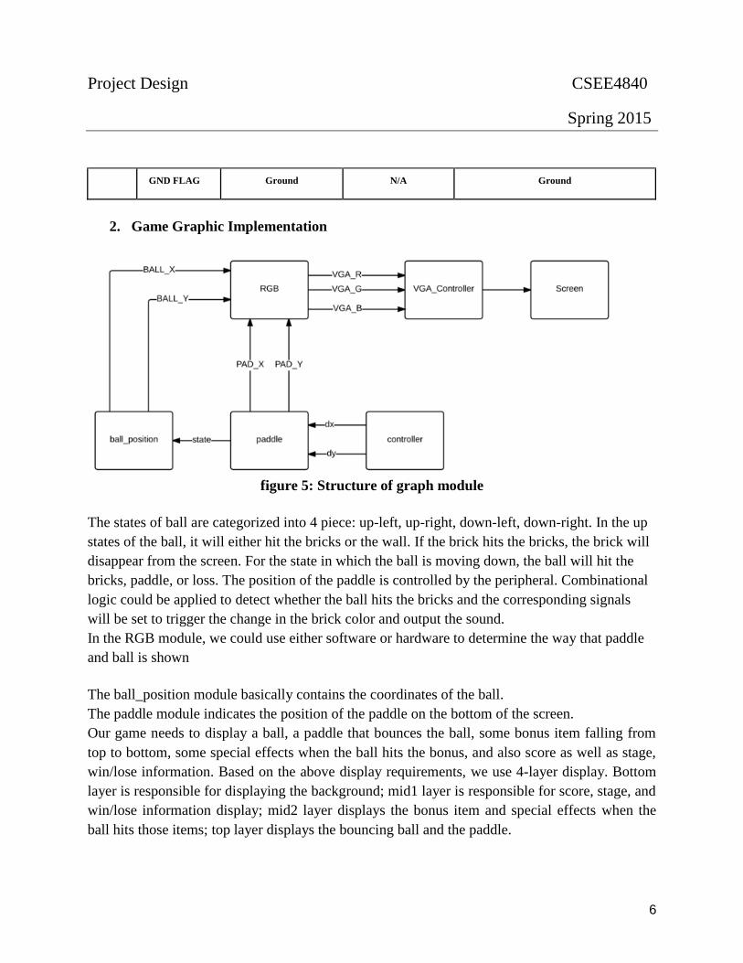
2. Game Graphic Implementation
figure 5: Structure of graph module
The states of ball are categorized into 4 piece: up-left, up-right, down-left, down-right. In the up
states of the ball, it will either hit the bricks or the wall. If the brick hits the bricks, the brick will
disappear from the screen. For the state in which the ball is moving down, the ball will hit the
bricks, paddle, or loss. The position of the paddle is controlled by the peripheral. Combinational
logic could be applied to detect whether the ball hits the bricks and the corresponding signals
will be set to trigger the change in the brick color and output the sound.
In the RGB module, we could use either software or hardware to determine the way that paddle
and ball is shown
The ball_position module basically contains the coordinates of the ball.
The paddle module indicates the position of the paddle on the bottom of the screen.
Our game needs to display a ball, a paddle that bounces the ball, some bonus item falling from
top to bottom, some special effects when the ball hits the bonus, and also score as well as stage,
win/lose information. Based on the above display requirements, we use 4-layer display. Bottom
layer is responsible for displaying the background; mid1 layer is responsible for score, stage, and
win/lose information display; mid2 layer displays the bonus item and special effects when the
ball hits those items; top layer displays the bouncing ball and the paddle.

Project Design CSEE4840
Spring 2015
7
Figure 6: Principle diagram for display module
For the display of each individual item, such as the ball, the board, bonus items, and the special
effects when the ball hit bonus items, as well as the backgrounds, we use sprites to implement
them and at the same time to save memory. Considering that there may be 3-6 bonus items, we
might need 7-10 sprites, far more less than 64, which means this scheme is workable.
As for the scan signal part, we use principle diagrams to describe it specifically.

Project Design CSEE4840
Spring 2015
8
Figure 7: Principle diagram for line scan controller
Figure 8: Principle diagram for frame scan controller
3. Audio Signal Processing
We are going to use low power audio codec SSM2603 to process sound signal. The SSM2603 is
a low power, high quality stereo audio codec for portable digital audio applications with one set

Project Design CSEE4840
Spring 2015
9
of stereo programmable gain amplifier line inputs and one monaural microphone input. The
SSM2603 software-programmable stereo output options provide the user with many application
possibilities. Its volume control functions provide a large range of gain control of the audio
signal[2]. Our main control hardware FPGA and we can connect SSM2603 to it. FPGA has
Linux operating system processor. Linux has codec driver interface for it. Our control hardware
FPGA and SSM2603 audio codec block diagram is shown below.
Figure 9: FPGA board

Project Design CSEE4840
Spring 2015
10
Figure 10: SSM2603 audio codec functional block diagram
The traditional system architecture is as follows:
Figure 11: Traditional system architecture

Project Design CSEE4840
Spring 2015
11
Linux audio codec driver has a lot of modules. ALSA module provides a unified interface to the
hardware and user application modules provide given functionalities to the end user. In our
project, we will insert the sound effect in user space and store it on hardware memory[3]. Then
through the SSM2603 codec the sound can be played.
The digital audio input can support the following four digital audio communication protocols:
right-justified mode, left-justified mode, I 2 S mode, and digital signal processor (DSP) mode.
The mode selection is performed by writing to the FORMAT bits of the digital audio interface
register (Register R7, Bit D1 and Bit D0). All modes are MSB first and operate with data of 16
to 32 bits. On the RECDAT output pin, the digital audio interface can send digital audio data for
recording mode operation. The digital audio interface outputs the processed internal ADC digital
filter data onto the RECDAT output.
The software control interface provides access to the user-selectable control registers and can
operate with a 2-wire (I2 C) interface. Within each control register is a control data-word
consisting of 16 bits, MSB first. Bit B15 to Bit B9 are the register map address, and Bit B8 to Bit
B0 are register data for the associated register map. SDIN generates the serial control data-word,
SCLK clocks the serial data, and CSB determines the I2 C device address. If the CSB pin is set
to 0, the address selected is 0011010; if 1, the address is 0011011.
III. Milestone Plan
For milestone 1, we are going to finish 25% of the whole project. We plan to show TA and
professor our bouncing ball, bricks and paddle on the screen. The wall instead of paddle bounces
the ball because paddle now is static. Once the brick is touched, it will vanish. And also the score
will increase.
For milestone 2, we are going to finish 50% of the whole project. At this point, the paddle can
move by controller and can bounce ball back.
For milestone3, we are going to finish 75% of the whole project. Since the sound effect happens
when the paddle bounces ball or a brick is touched, the sound effect is supposed to be added at
this point.
For the rest time, we may probably test our game again and again to make sure it works fine.
After that, if we have more time, we will improve our game by adding something to brick to

Project Design CSEE4840
Spring 2015
12
make it more interesting for players. For example, we can make some brick special once the ball
touches it, the score doubles. Or we can design some other bonus. Also, we plan to design the
game as a competition between two players or use more than one paddle to receive the ball or
use two balls instead of just one. All in all, the purpose of this time period is to embellish the UI
and improve the function of the game to make it more entertaining. We hope we can have a good
presentation at the end of the class.
Reference:
[1] http://www.makeuseof.com/tag/simple-brick-breaker-the-old-classic-game-remains-as-
addictive-as-it-was-before-iphone/
[2]http://www.analog.com/media/en/technical-documentation/data-sheets/SSM2603.pdf
[3]http://free-electrons.com/doc/embedded_linux_audio.pdf