
Brian Saghy (CE) - Team Leader Alejandro Lam (EE) Gaurav Patel (ME) Brian Payant (EE) Nathan...
71
Brian Saghy (CE) - Team Leader Alejandro Lam (EE) Gaurav Patel (ME) Brian Payant (EE) Nathan Pendleton (EE) Engineering Senior Design - Project 05400 Sustainable Platform Development for Self- positioning Microsystems Utilizing Magnetic Field Propulsion Critical Design Review Nov 11, 2005 Coordinator: Dr. Edward Hensel Team Mentor & Sponsor: Paul Stiebitz
-
date post
21-Dec-2015 -
Category
Documents
-
view
222 -
download
2
Transcript of Brian Saghy (CE) - Team Leader Alejandro Lam (EE) Gaurav Patel (ME) Brian Payant (EE) Nathan...

Brian Saghy (CE) - Team Leader
Alejandro Lam (EE)
Gaurav Patel (ME)
Brian Payant (EE)
Nathan Pendleton (EE)
Multidisciplinary Engineering
Senior Design - Project 05400
Sustainable Platform Development for Self-positioning Microsystems
Utilizing Magnetic Field Propulsion
Critical Design ReviewNov 11, 2005
Coordinator:
Dr. Edward Hensel
Team Mentor & Sponsor:
Paul Stiebitz

Presentation Overview
• Introduction
• Process Overview
• Design & Testing Details
• Budget Report
• Project Schedule
• Future Recommendations
• Conclusion
• Questions

Project Introduction and History
Swarms of small, intelligent objects can form a seemingly larger shape.
Future MEMS technology could make for microscopic robot.
Review of SD1

Previous Work
Does not work due to lack of static friction in fluid, and symmetric design.
Inertial DriveMagnetic Field
Propulsion
3D control issues
Non-robust design
Review of SD1

Magnetic Field Propulsion
•Tank has six high power magnetic coils on each side
•Chunxil drives itself by turning on internal coils to attract it to the desired wall
•Chunxil is able to determine location in tank by the strength of the EMF fields induced by the external coils
Review of SD1

Timing Diagram
N S E W F B N S E W F B W
N S E W F B N N S E W F B B N
S E W F B E N S E W F B S N S
E W F B F N S E W F B N N S E
Wake Up Signal Post Wake Up Delay Sleep Timer Running
North AC Signal Asserts Interrupt
DC Period
Sleep Delay
Review of SD1

SD2 Focus and Objectives
•Primary goals include assembly ease, modularity, re-programmability and charging ease.•Scalable mechanical and electrical engineering model which could be implemented using current & future small-scale technologies.•Utilize improvements over the last few years in microcontrollers and batteries•Start with small steps, rather than trying to tackle the whole project at once.

Process Overview
• Concept Development of Magnetics & Chunxil Design. Brainstorming (SD1)
• Feasibility Assessment of individual components (SD1)
• Analysis of Components (SD1/2)
• Engineering Model (SD2)

Desired Outcomes
• Ability to recharge the battery without opening the Chunxil
• Ability to change the Chunxil's control software without having to open/rebuild the Chunxil
• Ability to attach a debugger to the Chunxil while in operation
• Easier physical modification of Chunxil coils and battery, if necessary.
• Positioning control within a limited 1-dimension in the tank

Mechanical Design
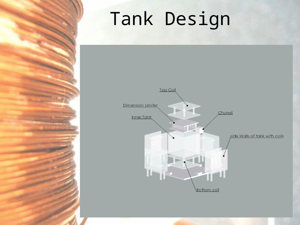
Tank Design

Chunxil Axis Limiter

Chunxil Cube

Chunxil Assembly

Charging/Programming Station

Software & Microcontroller
Design and Testing
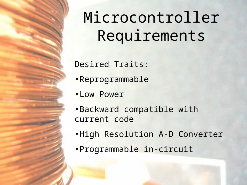
Microcontroller Requirements
Desired Traits:
•Reprogrammable
•Low Power
•Backward compatible with current code
•High Resolution A-D Converter
•Programmable in-circuit

FeaturesPIC
16LC716[Previous
Generation]
PIC 16F88[Current
Generation]
In-CircuitRe-
Programmable
No[single use]
Yes
RAM 128 Bytes 368 Bytes
Flash DataMemory
[holds dataduring power
loss]
No 256 Bytes
A/D precision 8 bits 10 bits[4x more
data]Software
Debugging No YesInstructionMemory
2048words
4096words
Low Poweroperation No YesI/O pins 13 16
Microcontroller Upgrade

PIC Pinout

PIC Engineering Model

Chunxil Software Flowchart

Chunxil Electronics

Chunxil PCB Design
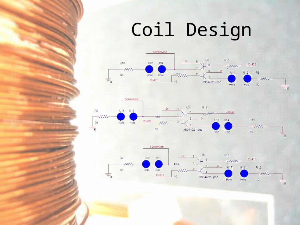
Coil Design

AC Position Sensing
+/-4.5mV Corner of Coil6"
+/- 58mV Corner of Coil0.25"
+/- 6mV Center of Coil6"
+/- 68mV Center of Coil0.25"
InducedVoltage Alignment
Distance fromTank Coil

Voltage Regulator
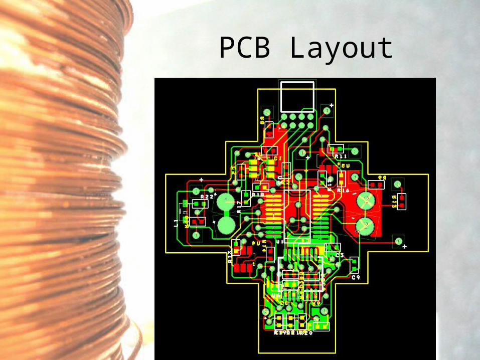
PCB Layout
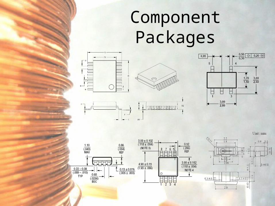
Component Packages

Assembly

Power, Programming, Debugging,& Charging

Power & Programming Requirements
• A Chunxil must be able to make 3 trips across the tank.
• The battery must be rechargeable, & able to recharge in less than 5 hours.
• A Chunxil shall be recharged, reprogrammed & debugged without being disassembled.
• All Chunxils must conform to a common interface standard, such that a universal reprogramming, recharging, and debugging method can easily be used for all Chunxils.

Deliverables
• A power source (battery) capable of providing ample power.
• A recharging method which is auto-controlled and easy to use.
• A reprogramming dock which allows data, debug, and power access to the microcontroller without opening the Chunxil case.

Power Consumption
ComponentMaximum
Current (mA)Expected
Time On (%)Net Power Usage(mA x 3V= mW)
Micro-controller 1 100% 3
Op-amps 1 x4 Op-Amps 70% 8.4
Transistor Base 2.6 50% 4
Chunxil Coil 90 50% 135
MiscellaneousLoss
3 100% 9
Voltage Regula-tor
1 100% 3
Total Power Consumed 162.4
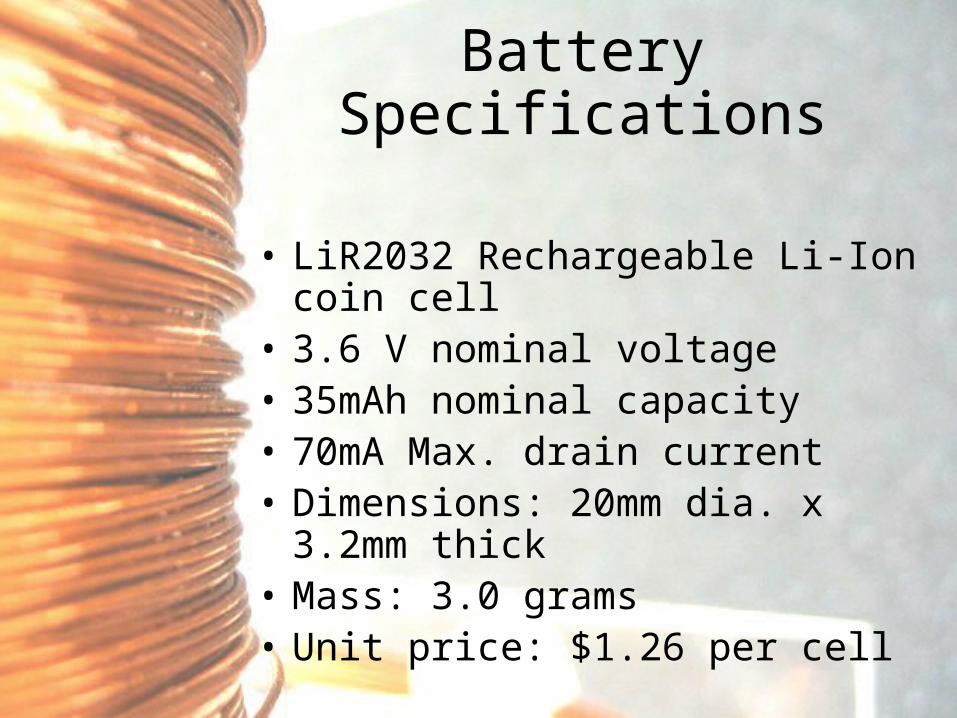
Battery Specifications
• LiR2032 Rechargeable Li-Ion coin cell• 3.6 V nominal voltage• 35mAh nominal capacity• 70mA Max. drain current• Dimensions: 20mm dia. x 3.2mm thick• Mass: 3.0 grams• Unit price: $1.26 per cell

Recharging Parameters
• The LiR-2032 can be recharged at 17mA per cell [constant current].
• A stand-alone Li-Ion charging microchip was found to be a good solution.
• The Linear Technologies LTC1733 is capable of providing 1A of constant current, and does not require an external MOSFET or current sensing resistor.

Connector Port Parameters
• The PIC 16F88 requires five (5) lines for programming [+3V, GND, PgC, Pgd, MCLR]
• Two (2) lines are needed for charging [Bat_Plus, GND]
• The GND line is shared for charging & programming.
• The Chunxil dock connector was chosen to be 8 pins, to allow for future expansion & keyed operation.

Docking Station
• [get mechanical drawing or actual picture of drawing station.]

Tank ElectronicsRedesign
Tank Electronics
• Power controls where modified to allow polarity change, which implies a direction change of the magnetic field.
• General testing was performed on the tank power supply system. Yielding a need to replace a faulty power supply.
• Unreliable wiring was replaced using proper wiring techniques.
• Safety concerns where addressed with respect to protecting the electronics and the user

Tank Electronics Schematic
AC or DC
5Vdc
5Vdc
5Vdc
CTRL2
CTRL1
CTRL3
+
-
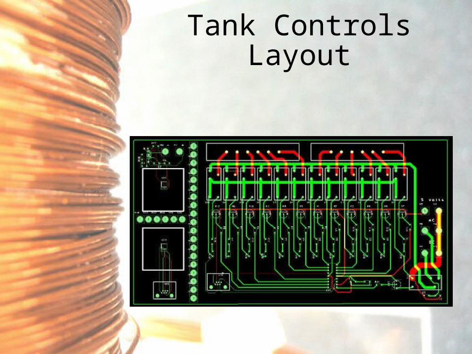
Tank Controls Layout

Tank Electronics Hardware

Budget Report

Schedule at Beginning of Quarter

Actual Schedule Followed

Future Recommendations & Ideas
•Wait to decrease size until after controls in 3D completed
•Increase size of tank coils for better multi-dimensional control
•Switch to using hall-effect sensors for position measurement, eliminate AC cycle
•Recharging and Programming using only inductors (No physical Connection)
• Wireless control of the Chunxil
• Use of multicolor LED’s inside, for color replications. Will add realism to the shape formed

Conclusion
● Proved to be very a challenging project
● Were able to overcome several obstacles
● Design should allow for easier transition of new groups to this project.
● Though we fell somewhat behind schedule, a working model is expected by the time of the demo in one week.

Questions?

Thank You

Sneaker Slides

PIC Feasibility AssessmentEvaluate each additional concept against
the baseline, score each attribute as: 1
= much worse than baseline concept 2 =
worse than baseline 3 = same as
baseline 4 = better than baseline 5=
much better than baseline
Cur
rent
( P
IC16
C17
6)
PIC 1
6F819
Pic
16F88
Pic
18F13
20
TI
MS
P430F11
3
Rel
ativ
e W
eigh
t
Suffi cient Student Skills? 3.0 3.0 3.0 3.0 1.0 2%
Size/ Weight/ Nano-Feasibility 3.0 3.0 3.0 2.0 1.0 13%
Cost of Chips 3.0 3.0 3.0 2.0 3.0 8%
Cost of Programmer,Burner, and Sof tware 3.0 3.0 3.0 3.0 1.0 3%
Compatible I SA 3.0 2.0 2.0 1.0 1.0 10%
Compatible Pin Layout/ Voltages 3.0 2.0 2.0 2.0 1.0 5%
Memory (Flash, Ram) 3.0 4.0 5.0 5.0 5.0 13%
Program in-circuit 3.0 5.0 5.0 5.0 5.0 12%
Suffi cient bit-ADC 3.0 4.0 4.0 4.0 4.0 18%
Power Usage 3.0 5.0 5.0 4.0 1.0 15%
Hardware Multiplier 3.0 3.0 3.0 5.0 5.0 3%
Low-Power Programming 3.0 5.0 5.0 3.0 5.0 5%
Weighted Score 3.3 4.1 4.2 3.7 3.1
Normalized Score 77.7% 96.8% 100.0% 88.0% 74.9%

Cube Feasibility Assessment*Evaluate each additional concept against
the baseline, score each attribute as: 1
= much worse than baseline concept 2 =
worse than baseline 3 = same as baseline
4 = better than baseline 5= much better
than baseline
Cur
rent
Chu
nxel
Cub
e (6
Sep
arat
e
Sid
es)
Prot
otyp
e 1:
Tw
o
shel
ls p
ut t
ogue
ther
Prot
otyp
e 2: U
se o
f
Exi
stin
g
Com
mer
cial
ly
Ava
ilable
1*1
*1 inc
h
Rel
ativ
e W
eigh
t
Chunxil Cube Size 3.0 1 5 25%
I nner Space for other components 3.0 2 4 21%
Waterproofi ng Capabilities 3.0 3 3 18%
Cost of Purchased Components? 3.0 4 2 4%
Ease of Assembly of a Full Chunxil
Everything I nside 3.0 2 4 7%
Modularity of Physical Parameter 3.0 3 3 7%
Nesting Ability 3.0 4 2 4%
Charging and Programming I nterface 3.0 5 1 14%
Weighted Score 3.0 2.6 3.4
Normalized Score 87.5% 75.0% 100.0%

Stabilization of Chunxil AxesFeasibility Assessment

Battery Feasibility Assessment
78.2%89.1%89.1%100.0%83.2%Normalized ScoreNormalized Score
2.83.23.23.63.0Weighted ScoreWeighted Score
7% 45553.0Price ($)Price ($)
4% 33333.0Average Lifespan (cycles)Average Lifespan (cycles)
0% 55443.0Internal Impedance (ohms)Internal Impedance (ohms)
21% 55443.0Max. Discharge rate [continuous] (mA)Max. Discharge rate [continuous] (mA)
18% 32113.0Normal Capacity (mAh)Normal Capacity (mAh)
11% 44443.0Voltage (v)Voltage (v)
25% 13453.0Size (mm)Size (mm)
14% 11233.0Weight / Mass (grams)Weight / Mass (grams)
Rela
tive W
eig
ht
Rela
tive W
eig
ht
LIR2477LIR2477LIR2450LIR2450LIR2430LIR2430LIR2032LIR2032
[Presumed][Presumed]SanyoSanyo
CR-1/3NCR-1/3N
Evaluate each additional concept against
the baseline, score each attribute as:
1 = much worse than baseline concept2 = worse than baseline3 = same as baseline4 = better than baseline5 = much better than baseline
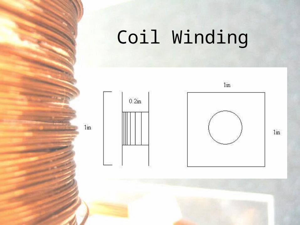
Coil Winding

Stabilization of Chunxil Axes
1) Widen Tank CoilsAdvantages:
Straighten Field Lines Inside Tank.
Increase Visibility
Disadvantages:
Physical Modification of Tank
Invalidate Past EMF Values

Wiki
•Online Collaboration
•Easy to edit
•Accessible from Anywhere

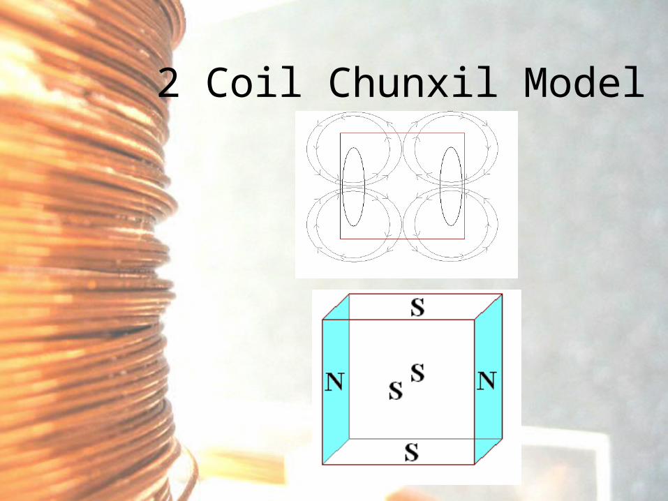
2 Coil Chunxil Model

Stabilization of Chunxil Axes
2) Simultaneous Activation of Opposite Coils Inside Chunxil
Advantages:
Greater Resistance to Spin
Opposing Field Directions on Opposite Chunxil Faces
Disadvantages:
Greater Power Consumption in Chunxil
More Complex Circuitry
More Complex Mathematical Model

1 Coil Chunxil Model
2 Coil Chunxil Model

Stabilization of Chunxil Axes
2) Simultaneous Activation of Opposite Coils Inside Chunxil
Advantages:
Greater Resistance to Spin
Opposing Field Directions on Opposite Chunxil Faces
Disadvantages:
Greater Power Consumption in Chunxil
More Complex Circuitry
More Complex Mathematical Model

Stabilization of Chunxil Axes
3) Simultaneous Activation of Opposite Coils On Tank
Advantages:
Straightens Field Lines Inside Tank
Disadvantages:
Needs Two Coils Inside Coil Activated
Greater Chance of Chunxil Spinning on “Pushing” Half of the Tank
More Complex Tank Circuitry
More Complex Mathematical Model

Stabilization of Chunxil AxesHybrid Model
Movement Cycle External InternalE W E W
West to East - West Side of Tank 1a + On On1b + - Off Off
West to East - East Side of Tank 1a + On On1b + - On On
+ = “Pulls Toward”
- = “ Pushes Away”

Velocity Control
• Increase Tank Coil Diameters
• Decrease Current
• Lessen # of Turns on Coil
• Pulse Coils

Proteus Gen 1B Navigation ControlDifference = North Voltage – South Voltage
NO
RT
H C
OIL
SO
UT
H C
OIL
X Position
50mV
40mV
30mV
20mV
10mV
Target: Difference=30mV
D=20mV
D=0mV
D=40mV
D=30mV
Review of SD1

Initial Battery saver circuit

Re-Designed Op-Amp circuit

Other Improvements

Coil Control Circuit

Tank Electronics
AC or DC
5Vdc
5Vdc
5Vdc
CTRL2
CTRL1
CTRL3
+
-