Brian Hanna Assembly Document METEOR µController The ...
10
Brian Hanna Assembly Document METEOR μController The microcontroller will be populated using heat wave. The microcontroller requires several capacitors which will all be populated. Microcontroller Pin1 Pin64 10μF Capacitors 0.1μF Capacitors
Transcript of Brian Hanna Assembly Document METEOR µController The ...

Brian Hanna Assembly Document METEOR µController
The microcontroller will be populated using heat wave.
The microcontroller requires several capacitors which will all be populated.
Microcontroller
Pin1
Pin64
10µF Capacitors
0.1µF Capacitors
Brian Hanna Assembly Document METEOR µController
The manual reset switch, the resistors and the capacitor will be populated.
For the crystals both crystals and all of the capacitors associated with them will be
populated.
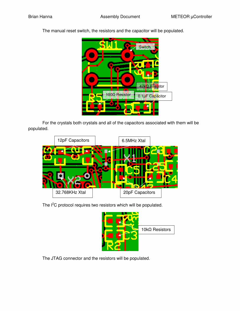
The I2C protocol requires two resistors which will be populated.
The JTAG connector and the resistors will be populated.
Switch
100Ω Resistor
47kΩ Resistor
0.1µF Capacitor
32.768KHz Xtal
6.5MHz Xtal
20pF Capacitors
12pF Capacitors
10kΩ Resistors

Brian Hanna Assembly Document METEOR µController
The power connectors will be populated.
After populating these parts the basic hardware for downloading code on to the
microcontroller is in place and to test the successful download of code to the board as well as
test the I2C address transmission the main code will be commented so that it only initializes the
I2C module and transmits an address. The SCL and SDA lines will be probed to verify the
desired address is being sent and the lines are behaving as anticipated. A start bit should occur
first which is characterized by holding the SCL line high while the SDA line gets pulled low. This
will then be followed by a series of bits corresponding to the slaves address starting with the
most significant bit followed by a logically low bit.
After verifying both I2C and code downloading abilities of the system the validity of the
received data will be tested by populating a single temperature sensor. That way the ability of
the micro-controllers code to communicate with slave devices can be tested and verified. The
JTAG
Connector
0Ω
Resistors
Gnd
+3.3V
+5V

Brian Hanna Assembly Document METEOR µController
1kΩ and 1.96kΩ resistors will not be soldered on and will have the terminals shorted out. This
resistor was originally going to be part of a voltage divider that was suggested to fix the problem
of a 5V logical high level being transmitted by the temperature sensors. Instead the
temperature sensors are going to be powered at +3.3VDC and the voltage divider is going to be
omitted since testing proved that it functions properly. Along with the temperature sensor the
0.1µF caps and a 0Ω resistor will be used to short the ADD1 pin of the temperature sensor to
ground via R15 while ADD0 will be left floating. This will give the device a slave address of
0x49.
Once the temperature sensor is all set to be tested the output will be probed to make
sure it is in the +3.3V range. The output can be probed to make sure the value of temperature
being outputted is reasonable for room temperature or the debugger can be used to step
through the code and observe the values in memory. After this test an incorrect address will be
sent to the temperature sensor to make sure that it is only responding to the address chosen by
the ADD pins biasing. After verification of the one sensor the other on-board and all the
0Ω Resistor
1kΩ Resistor
1.96kΩ Resistor
Temperature
Sensor
0.1µF Capacitor

Brian Hanna Assembly Document METEOR µController
external temperature sensors will be populated making sure each one has a unique slave
address as determined by ADD1 and ADD0 biasing. The external temperature sensors will be
connected to the main board by soldering a wire into each of the vias.
For the humidity sensor and the GPS device each have associated cables that will be
soldered together to go into a 2 by 5 connector that mates with a header on the PCB board.
The resistors called for in the respective datasheets will also be soldered on.
+3.3V
SCL
SDA
Gnd

Brian Hanna Assembly Document METEOR µController
The humidity sensor produces an analog output where the voltage level can be used in
an equation to determine the humidity. This voltage level will be probed and checked to see if
the result is reasonable compared to the actual humidity of the room using the relationship
provided on the datasheet of voltage to humidity. At 85% relative humidity this sensor is
outputting around +3.3V and at 10% relative humidity it is outputting around +1.2V. Also after
repeatedly exhaling on the humidity sensor the humidity should increase.
The GPS device outputs a logical high value around +2.85V which will be probed to
make sure it is outputting near this area. To verify the data the debugger will be used to step
through the code and the data will be read from memory. The data will be compared to the
approximate GPS coordinates of Rochester and repeated measurements will show a change for
the UTC time recorded. To further verify accurate results the platform will be driven to Vestal
and after waiting a period of time for the device to reacquire the satellites the data will be
Humidity Sensor (Left to Right)
Pin 1 Gnd, Pin3 +5V, Pin5 IRes, Pin7 IHum, Pin9 Gnd
GPS (Left to Right)
Pin 2 En, Pin4 Gnd, Pin6 Rx, Pin8 Tx, Pin10 +3.3V
10kΩ Resistors
10MΩ Resistor

Brian Hanna Assembly Document METEOR µController
checked to verify that it is different than the previous measurement and that the new data is
correct using a handheld consumer GPS.
The pressure sensors and the capacitors and voltage divider resistor networks needed
for them will all be populated.
The pressure sensors were designed to output an analog output of up to +5V which is
above the microcontrollers threshold so a voltage divider was implemented to cut this voltage in
half putting the maximum output well underneath the threshold. This voltage division is taken
into consideration in the equation provided in the datasheet that is used to calculate the
pressure based on the voltage level the sensor is outputting. Using the debug mode the
converted value of the original analog voltage will be stored in a variable and can be moused
over to check the validity of the data compared to the forecast of the actual pressure for the day.
The RS232 driver and the analog switch will be populated using heat wave. The resistor
and the capacitors for these chips will also be populated.
47kΩ Resistors
470pF Capacitors
1µF Capacitors
0.1µF Capacitors
Large Pressure Sensor (left to right) Pin1 VOUT, Pin2 Gnd, Pin3 +5V
Small Pressure Sensor (left to right) Pin1 VOUT, Pin2 Gnd, Pin3 +5V

Brian Hanna Assembly Document METEOR µController
These will be used to verify the generation and transmission of the packet of data that
will be sent to the 2m radio subsystem. This data can be probed by an oscilloscope to verify the
proper 1200 baud rate is being achieved and the desired characters ACII equivalent is being
sent. After combining all of the subsystems of the IP the results can be tested by transmitting
this data to a radio in mission control which is communicating with a computers hyperterminal.
This way both the quality and transmission of the data can be tested.
The headers for the eight camera power signals, the four video mux signals and the four
signals for SPI transmission of the OSD text to be displayed will be populated.
10kΩ Resistors
Analog
Switch
1µF Capacitors RS232 Driver

Brian Hanna Assembly Document METEOR µController
The code pertaining to selecting and powering the cameras will be tested by enabling
and selecting one camera only so the signals stay constant and probing the camera power lines
as well as the video mux lines: A0 – A3 to make sure they are the desired level. A3 is the
enable for video mux chip 2 and A2 is the enable for video mux chip 1. Camera 1 is selected
when video mux 1 is enabled and A1 and A0 are low. From there the other cameras are
selected by counting in binary and switching mux chips after using all combinations of A1 and
A0. Breakpoints can be used to stop the execution of the code after the camera channel has
been switched so that the values stay high and can be easily measured before switching
channels again.
The radio connector will be populated.
The SD card socket will not be populated due to a design flaw. A new PCB design was
created to remedy this however after submitting a request for an order the order was ignored. It
was not discovered that the new boards were never ordered until it was too late to order the
boards and have enough time to repopulate them.
Additionally there are four extra I/O pins that were routed which can be used for signals
such as fire the rocket or anything else that is needed. This will not be populated until all
systems have been approved and the platform has been deemed launch ready.
When the design is finished it shoud look like this.
Cam Power 5
Cam Power 6
Cam Power 7
Cam Power 8
Cam Power 1
Cam Power 2
Cam Power 3
Cam Power 4 A0 A1 A2 A3
OSD Data, Clk
OSD Rx, Slave Sel
O_Radio_Status
I_Radio_Tx
O_Radio_Rx
Gnd
I_Radio_Rx_Detect
O_Radio_M0
I_Radio_M1
O_Radio_PTT

Brian Hanna Assembly Document METEOR µController