Breaker Basics and New Technology - · PDF fileand New Technology Breaker Basics By: ... Low...
65
and New Technology Breaker Basics By: Scott Basinger, P.Eng. Eaton Electrical Edmonton
Transcript of Breaker Basics and New Technology - · PDF fileand New Technology Breaker Basics By: ... Low...
and New Technology
Breaker Basics
By: Scott Basinger, P.Eng.Eaton Electrical
Edmonton
��������������������� ����� ���������������������������������� ����� �������������
�������� �� ����������������������������������� �� ���������������������������
��� ������ ����� � � ����������� ����������� ������ ����� � � ����������� ��������
� ������ ���������� ��� ������ ���������� ���� ���� ������ �� ������ ��� ������ �
����������������� �������� ���� ������������������������ �������� ���� �������
Purpose
Circuit Breaker History
� First Developed at the request of Fire Inspection Authorities in the US in the 1920’s to provide better protection against fires.
� These fires were caused by users of electrical power who were bridging plug fuses with pennies or replacing fuses with ratings too high for the wires installed.
� Modern breaker design was primarily made possible by the development of the arc chute by Dr. Slepian of Westinghouse.

Breaker Classifications
� MCCB – Molded Case Circuit Breaker� This presentation is primarily about MCCB’s
� ICCB – Insulated Case Circuit Breaker� Same standard as MCCB’s with some features
found in LVPCB’s
� LVPCB – Low Voltage Power Circuit Breaker

Marking and Terminology
Molded Case Circuit BreakersMarking and Terminology
� Voltage Rating� RMS AC voltage or DC Voltage at which the breaker is
designed to operate.
� Breaker voltage markings on MCCB’s are significant and relate to the systems they may be used in.
� “Straight ratings” – 600V, 480V, 240V
� “Slash ratings” – 600Y/347V, 120/240V
� Current Rating� RMS AC current or DC current rating which the breaker will
carry continuously in open air.
Molded Case Circuit BreakersMarking and Terminology
� Ambient Temperature� Temperature of the air surrounding the breaker itself� Not necessarily room temperature
� Interrupting Rating� Highest RMS symmetrical AC (or DC ) current which a breaker is
required to interrupt under specified test conditions.
� Switching Duty Rated� Breakers marked with SWD for breakers tested to switch florescent
lighting loads on a regular basis.
� 100% Rated Breakers� Breakers must be marked specifically for 100% continuous operation
in enclosures. All others are 80%.

Breaker Elements
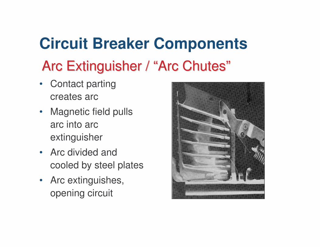
Arc Extinguisher / Arc Extinguisher / ““Arc ChutesArc Chutes””• Contact parting
creates arc
• Magnetic field pulls arc into arc extinguisher
• Arc divided and cooled by steel plates
• Arc extinguishes, opening circuit
Circuit Breaker Components
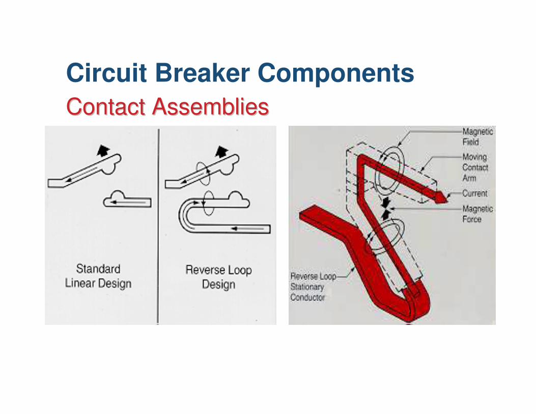
Contact AssembliesContact AssembliesCircuit Breaker Components
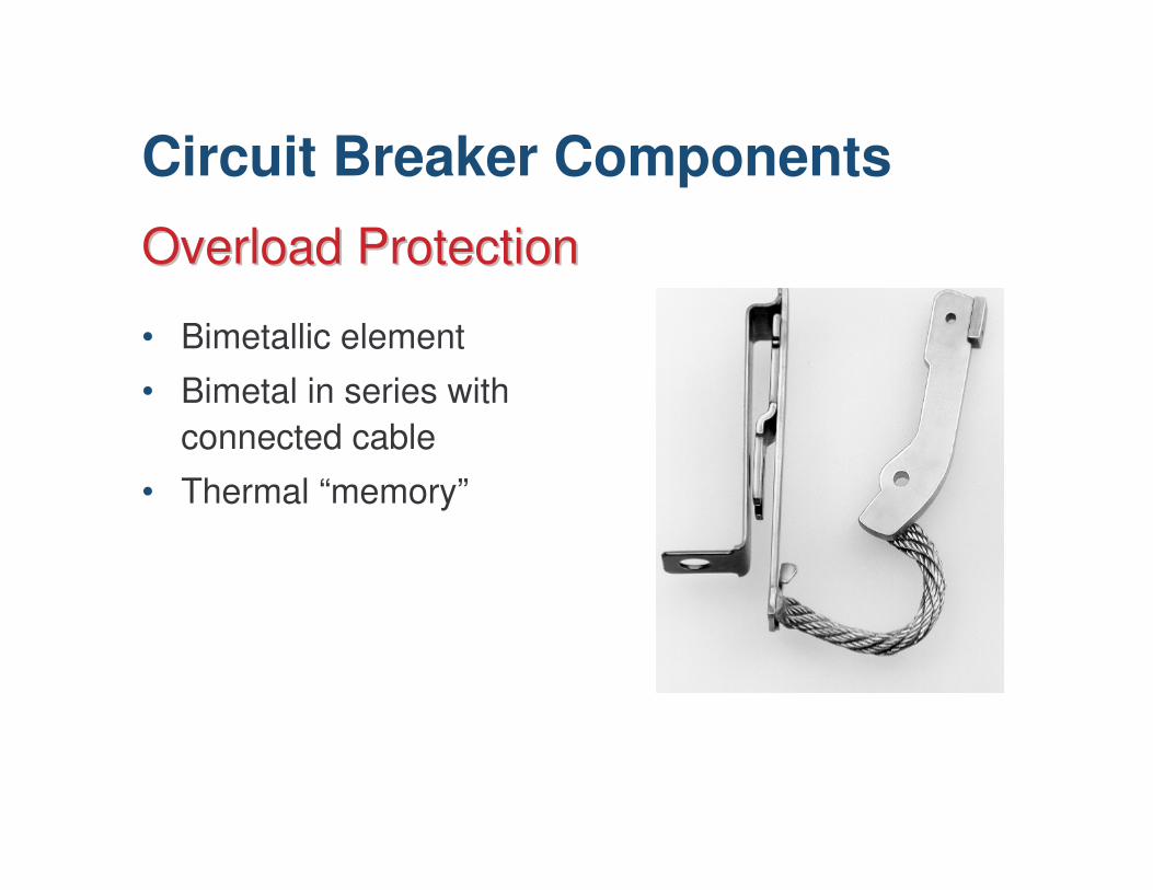
• Bimetallic element
• Bimetal in series with connected cable
• Thermal “memory”
Overload ProtectionOverload Protection
Circuit Breaker Components
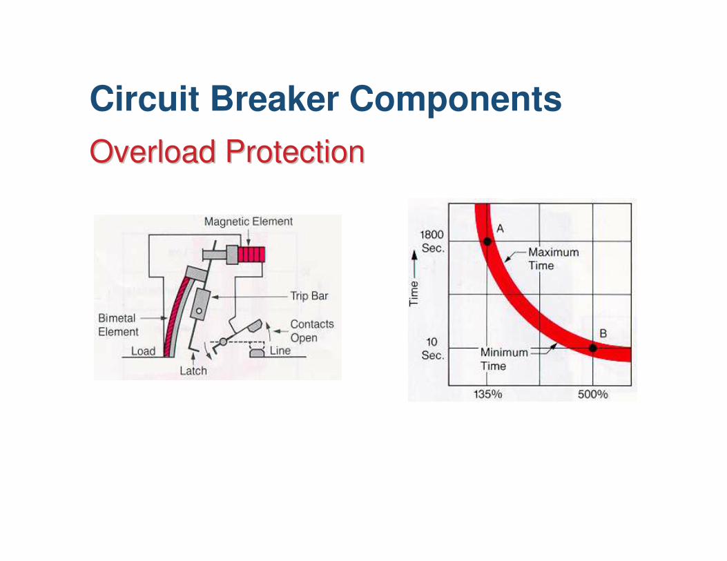
Overload ProtectionOverload Protection
Circuit Breaker Components
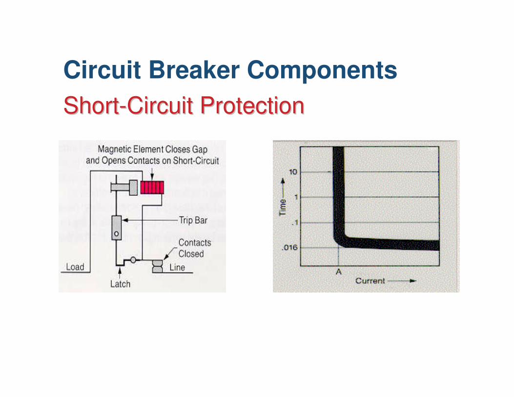
ShortShort--Circuit ProtectionCircuit ProtectionCircuit Breaker Components
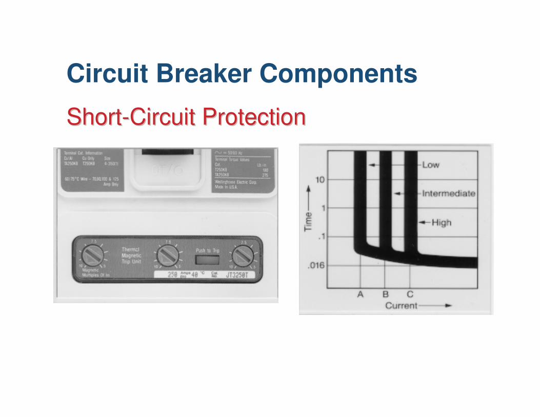
ShortShort--Circuit ProtectionCircuit Protection
Circuit Breaker Components
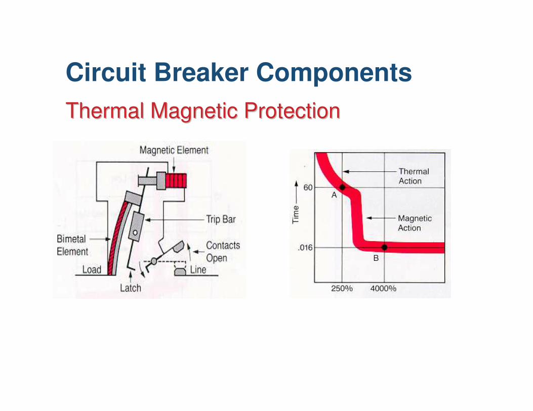
Thermal Magnetic ProtectionThermal Magnetic Protection
Circuit Breaker Components
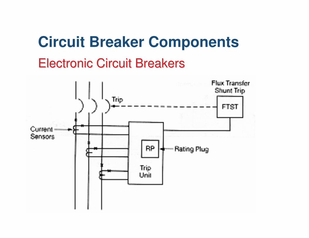
Electronic Circuit BreakersElectronic Circuit Breakers
Circuit Breaker Components
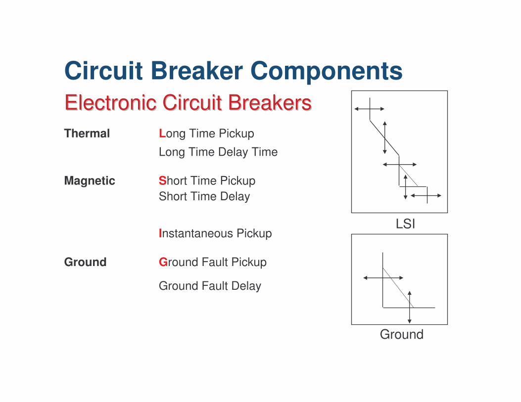
Thermal Long Time Pickup
Long Time Delay Time
Magnetic Short Time PickupShort Time Delay
Instantaneous Pickup
Ground Ground Fault Pickup
Ground Fault DelayTime
Electronic Circuit BreakersElectronic Circuit Breakers
LSI
Ground
Circuit Breaker Components
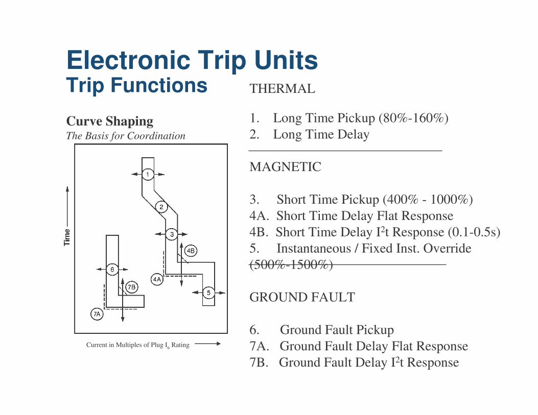
Curve ShapingThe Basis for Coordination
THERMAL
1. Long Time Pickup (80%-160%)2. Long Time Delay
MAGNETIC
3. Short Time Pickup (400% - 1000%)4A. Short Time Delay Flat Response4B. Short Time Delay I2t Response (0.1-0.5s)5. Instantaneous / Fixed Inst. Override (500%-1500%)
GROUND FAULT
6. Ground Fault Pickup7A. Ground Fault Delay Flat Response7B. Ground Fault Delay I2t Response
Current in Multiples of Plug In Rating
Electronic Trip UnitsTrip Functions
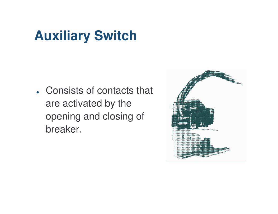
� Consists of contacts that are activated by the opening and closing of breaker.
Auxiliary Switch
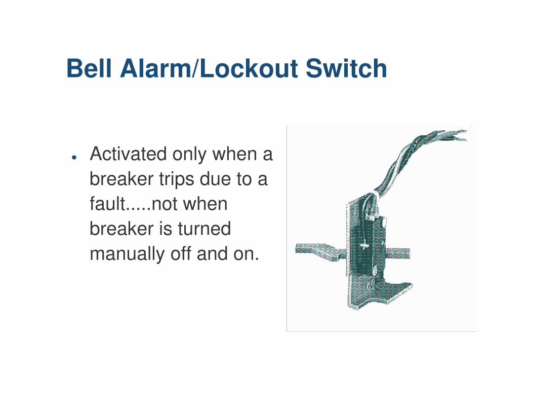
� Activated only when a breaker trips due to a fault.....not when breaker is turned manually off and on.
Bell Alarm/Lockout Switch
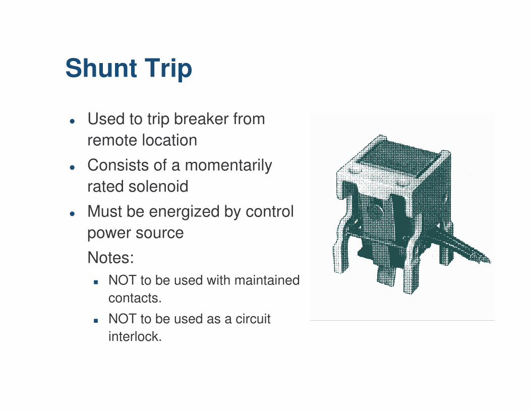
� Used to trip breaker from remote location
� Consists of a momentarily rated solenoid
� Must be energized by control power source
Notes:� NOT to be used with maintained
contacts.
� NOT to be used as a circuit interlock.
Shunt Trip
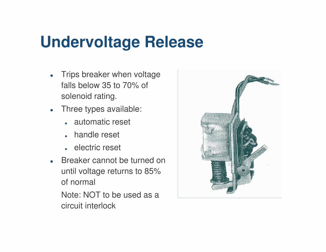
� Trips breaker when voltage falls below 35 to 70% of solenoid rating.
� Three types available:
� automatic reset
� handle reset
� electric reset
� Breaker cannot be turned on until voltage returns to 85% of normal
Note: NOT to be used as a circuit interlock
Undervoltage Release
Standard Requirements
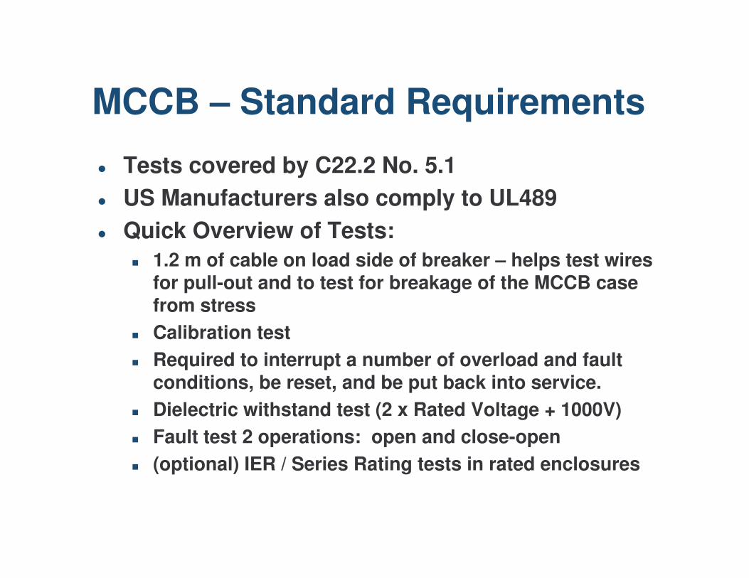
� Tests covered by C22.2 No. 5.1� US Manufacturers also comply to UL489� Quick Overview of Tests:
� 1.2 m of cable on load side of breaker – helps test wires for pull-out and to test for breakage of the MCCB case from stress
� Calibration test� Required to interrupt a number of overload and fault
conditions, be reset, and be put back into service.� Dielectric withstand test (2 x Rated Voltage + 1000V)� Fault test 2 operations: open and close-open� (optional) IER / Series Rating tests in rated enclosures
MCCB – Standard Requirements
Unusual Operating Conditions
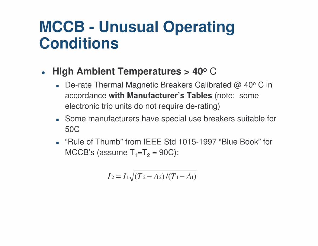
� High Ambient Temperatures > 40o C� De-rate Thermal Magnetic Breakers Calibrated @ 40o C in
accordance with Manufacturer’s Tables (note: some electronic trip units do not require de-rating)
� Some manufacturers have special use breakers suitable for 50C
� “Rule of Thumb” from IEEE Std 1015-1997 “Blue Book” for MCCB’s (assume T1=T2 = 90C):
MCCB - Unusual Operating Conditions
)/()( 112212 ATATII −−=
� Low Temperatures
MCCB - Unusual Operating Conditions
� Very Low Ambient Temperatures� Ref: IEEE Standard 1015-1997 Blue Book MCCB and
ICCB’s –5C� Ratings from one manufacturer:
� Environment Duty –20C -> 50C (CSA listed)� Typically –5C -> 40C
� Change of grease required to perform at low temperatures represents a material change to the breaker.
� Use of breakers below temperatures listed by the manufacturer may require special consideration, such as the use of a thermostat / space heater in the enclosure. Refer to manufacturer.
MCCB - Unusual Operating Conditions
� High X/R� Molded case breakers and Power Circuit Breakers are
evaluated differently for X/R� If System X/R > Standard X/R, no de-rating is required.� Power Breakers are tested with X/R ratio of 6.6� MCCB’s are tested with varying X/R :
� Tested X/R varies from 6.6 to 1.75 depending on interrupting rating.
� Can obtain multiplication factors for short circuit interruptingrating and ranges in IEEE Blue Book
� Harmonics� May affect the accuracy of “Peak Sensing” Electronic Trip
Units / Relays. Modern protective relays that use RMS sensing typically do not have this issue.
MCCB - Unusual Operating Conditions

� High Altitude > 6000 Ft� Dielectric is air, which is thinner at high altitude.� Affects both the Voltage and Current Rating.� IC usually unchanged if Voltage is de-rated.
� One Manufacturer:− Typ. -3% V per 1000 ft over 6000 with IC remaining as
published.− Typ. De-rate current equal to a 3C increase in Ambient
per 1000 ft over 6000 (in addition to standard 80% de-rating)
− Always use manufacturer tables.
MCCB - Unusual Operating Conditions
� Moisture� High Humidity is usually remedied by space heaters /
thermostat to prevent condensation.� Incorrect installation of panel.� Sample – breaker from outdoor panel that was allowing
water ingress.
MCCB - Unusual Operating Conditions
Common Errors
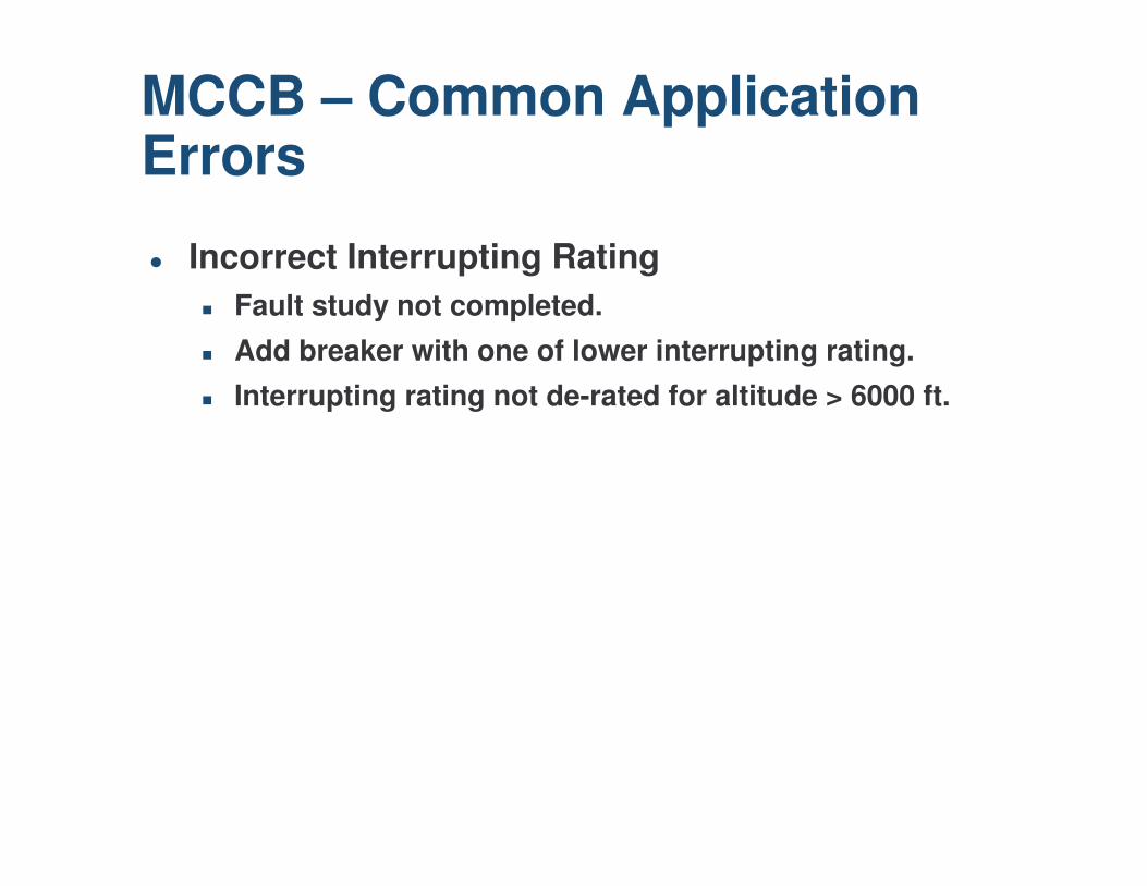
� Incorrect Interrupting Rating� Fault study not completed.� Add breaker with one of lower interrupting rating.� Interrupting rating not de-rated for altitude > 6000 ft.
MCCB – Common Application Errors
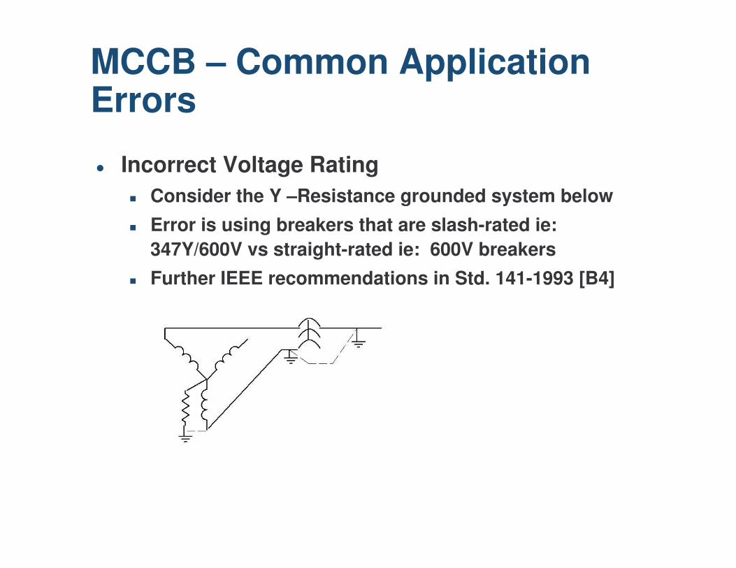
� Incorrect Voltage Rating� Consider the Y –Resistance grounded system below� Error is using breakers that are slash-rated ie:
347Y/600V vs straight-rated ie: 600V breakers� Further IEEE recommendations in Std. 141-1993 [B4]
MCCB – Common Application Errors

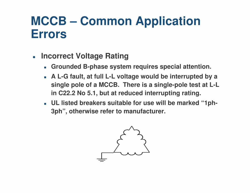
� Incorrect Voltage Rating� Grounded B-phase system requires special attention.� A L-G fault, at full L-L voltage would be interrupted by a
single pole of a MCCB. There is a single-pole test at L-L in C22.2 No 5.1, but at reduced interrupting rating.
� UL listed breakers suitable for use will be marked “1ph-3ph”, otherwise refer to manufacturer.
MCCB – Common Application Errors
� Incorrect current rating� Breakers, unless noted as “100% Rated” are 80% rated
in enclosures.� May cause nuisance tripping.
MCCB – Common Application Errors
� Use of “Refurbished” molded case circuit breakers.
MCCB – Common Application Errors

Better Protection

� Breakers and Relaying� Only simple provisions (shunt trip, trip coil) are required
to trip a breaker safely.� Allows many enhanced protection options via external
or internal breaker relaying.
MCCB – Enhanced Protection Options
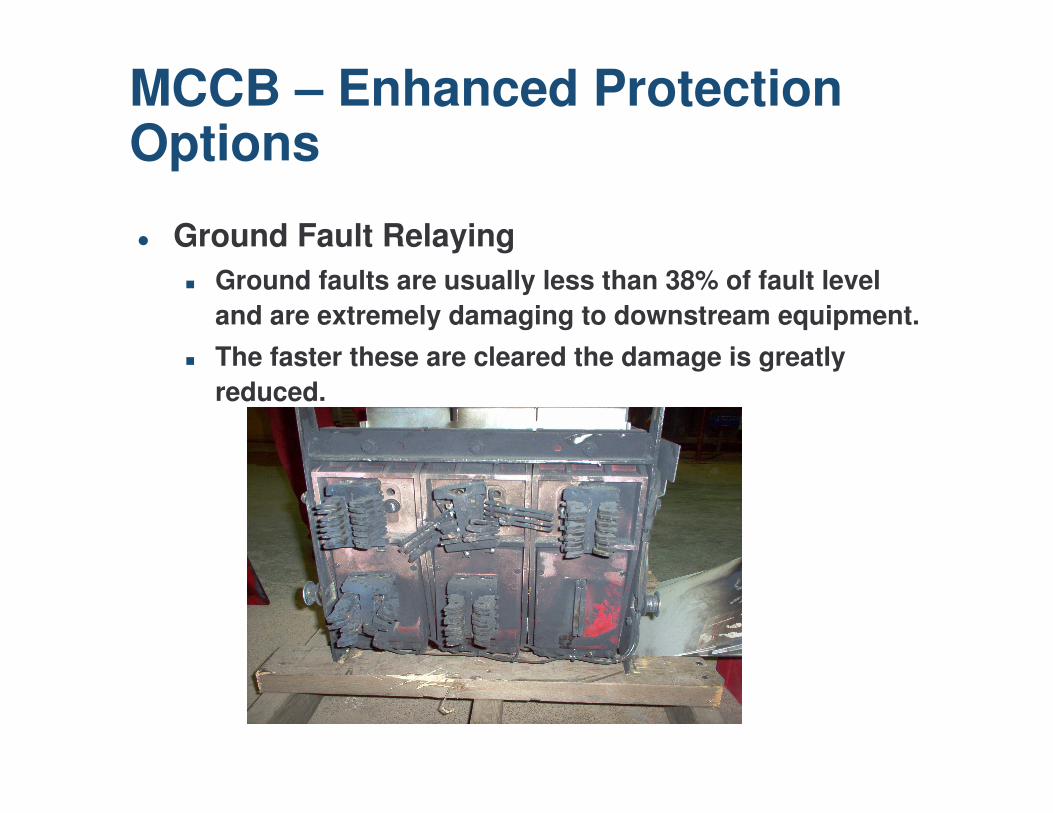
� Ground Fault Relaying� Ground faults are usually less than 38% of fault level
and are extremely damaging to downstream equipment.� The faster these are cleared the damage is greatly
reduced.
MCCB – Enhanced Protection Options
� Series Ratings (IER)
“New” MCCB Technology / Advanced Applications
� Selectively Coordinated Systems
“New” MCCB Technology / Advanced Applications
Selectively Coordinated Systems
Zone selective interlocking is a means by which two or more selectively coordinated trip devices can communicate and alter their preset tripping mode to provide faster response time for upstream fault conditions. This allows the nearest upstream breaker from the faulted zone to clear the circuit in the shortest time possible and reduce the system damage level potential.
Selectively Coordinated Systems
LVPCB’s with MCCB’s• Full discrimination
• Optimum continuity of service
• Short Time Delay - Allows the main breaker to remain closed for up to 30 cycles, but
• Subjects equipment to high mechanical and thermal stresses
• Higher equipment cost• Larger equipment size• Greater arc flash hazard risks
• Short Time Delay
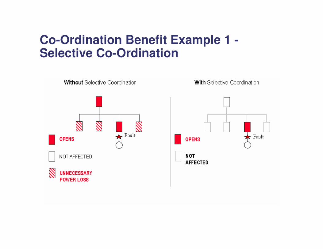
Co-Ordination Benefit Example 1 -Selective Co-Ordination
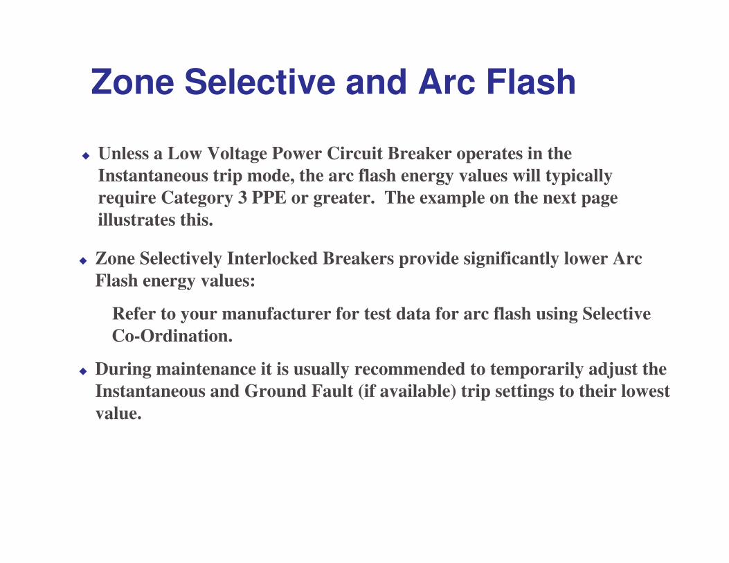
� Zone Selectively Interlocked Breakers provide significantly lower Arc Flash energy values:
Refer to your manufacturer for test data for arc flash using Selective Co-Ordination.
� During maintenance it is usually recommended to temporarily adjust the Instantaneous and Ground Fault (if available) trip settings to their lowest value.
Zone Selective and Arc Flash
� Unless a Low Voltage Power Circuit Breaker operates in the Instantaneous trip mode, the arc flash energy values will typically require Category 3 PPE or greater. The example on the next pageillustrates this.
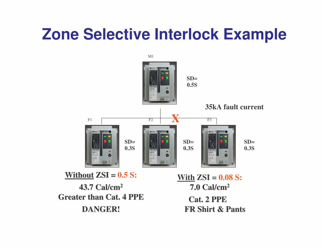
Zone Selective Interlock Example
SD=0.5S
SD=0.3S
SD=0.3S
SD=0.3S
M1
F1 F2 F3X35kA fault current
WithoutWithout ZSI =ZSI = 0.5 S:43.7 Cal/cm43.7 Cal/cm22
Greater than Cat. 4 PPEGreater than Cat. 4 PPEDANGER!DANGER!
With ZSI = 0.08 S:7.0 Cal/cm7.0 Cal/cm22
FR Shirt & PantsFR Shirt & PantsCat. 2 PPECat. 2 PPE

Home Safety
� Arc Fault Circuit Interrupters – Home Safety
“New” MCCB Technology / Advanced Applications
The CEC and AFCI
� CEC� 26-722(f): Branch circuits that supply receptacles installed
in sleeping facilities of a dwelling unit shall be protected by an arc-fault circuit interrupter.
� 26-722(g): For the purposes of paragraph (f), an arc-fault circuit interrupter means a device intended to provide protection from the effects of arc-faults by recognizing characteristics unique to arcing and functioning to de-energize the circuit when an arc-fault is detected.
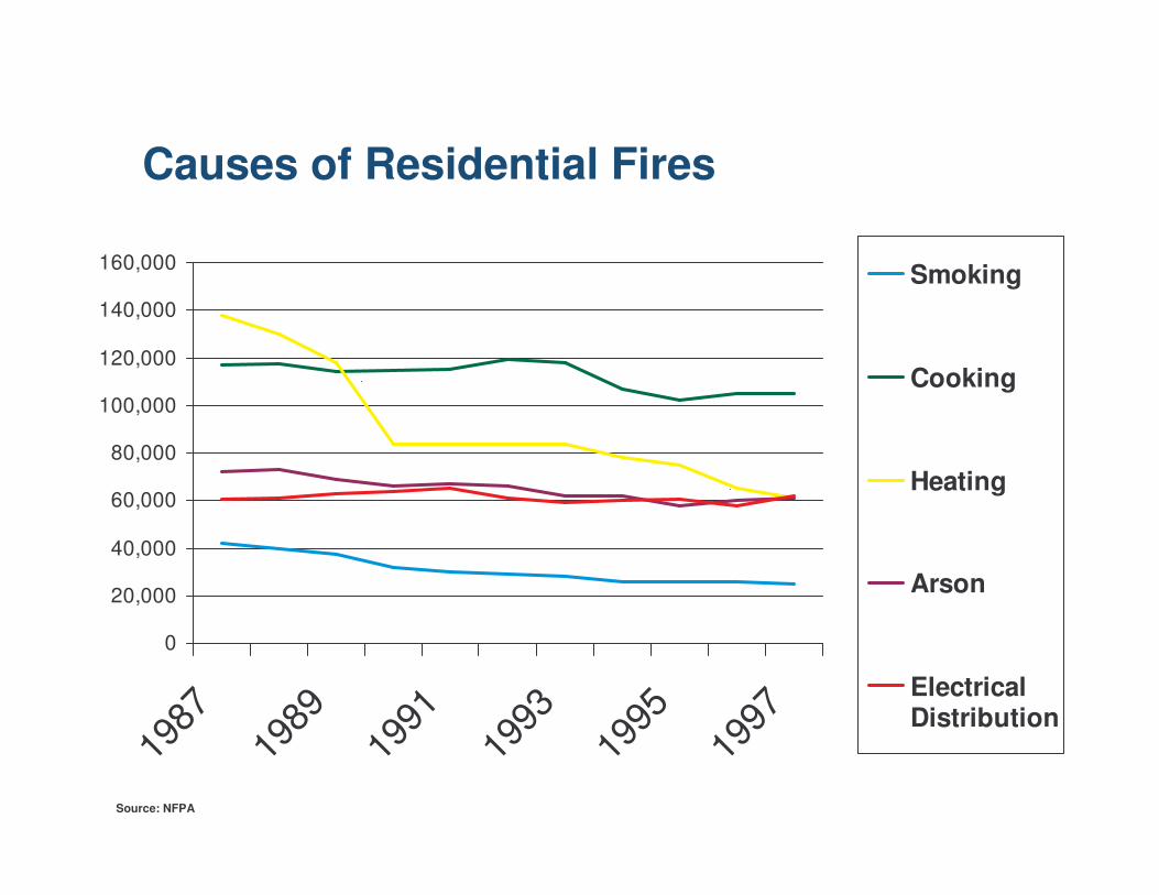
Causes of Residential Fires
Source: NFPA
0
20,000
40,000
60,000
80,000
100,000
120,000
140,000
160,000
1987
1989
1991
1993
1995
1997
Smoking
Cooking
Heating
Arson
ElectricalDistribution
Where Do Electrical Fires Start?
� Study conducted by NEMA task force
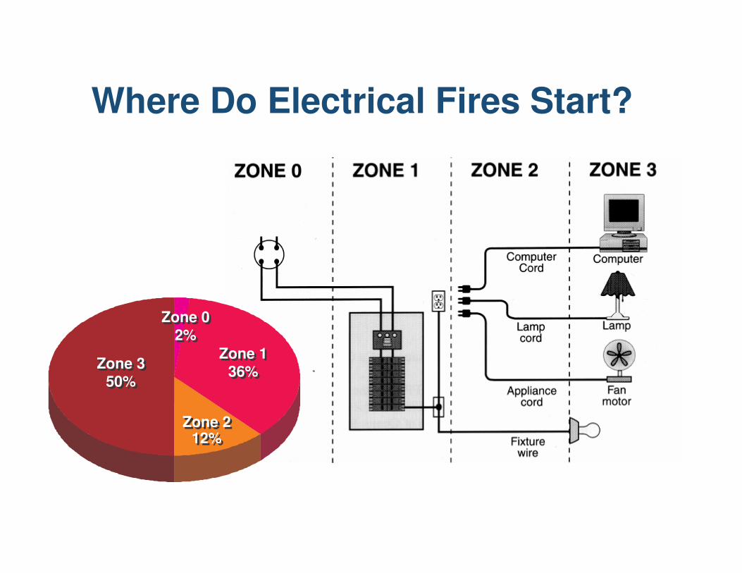
Where Do Electrical Fires Start?
Zone 350%
Zone 350%
Zone 136%
Zone 136%
Zone 212%
Zone 212%
Zone 02%
Zone 02%
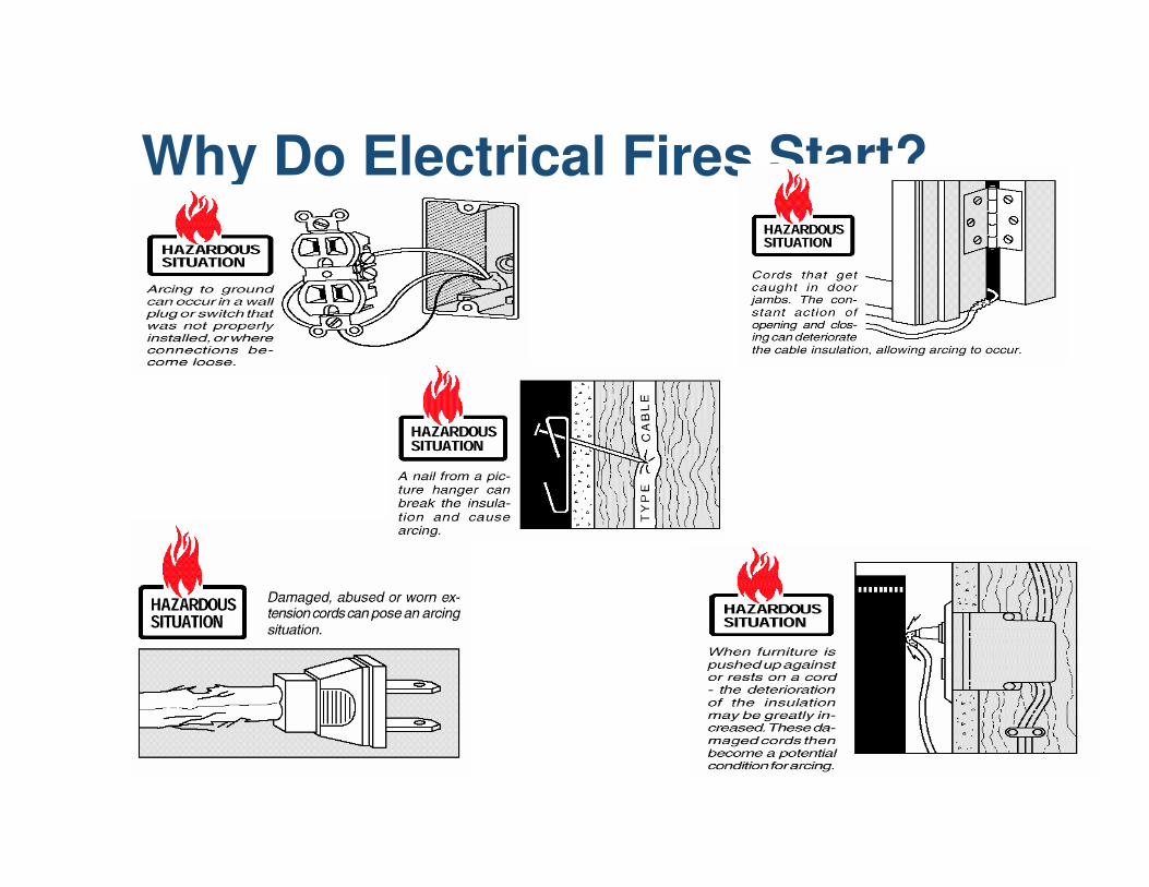
Why Do Electrical Fires Start?
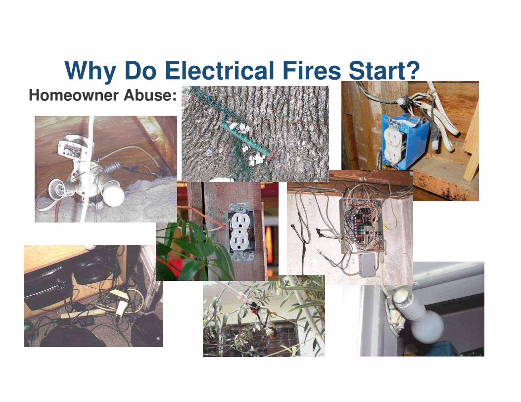
Why Do Electrical Fires Start?Homeowner Abuse:
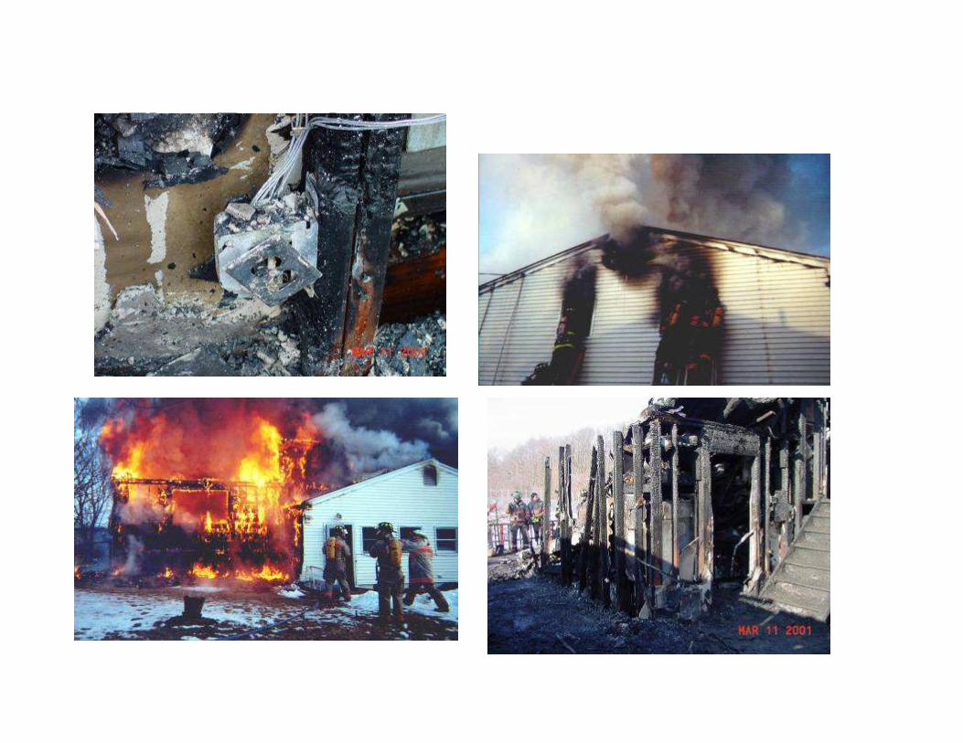
The Results:
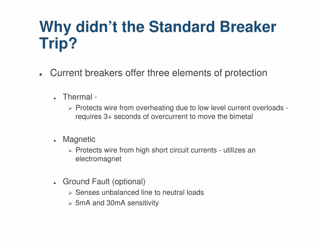
Why didn’t the Standard Breaker Trip?
� Current breakers offer three elements of protection
� Thermal -� Protects wire from overheating due to low level current overloads -
requires 3+ seconds of overcurrent to move the bimetal
� Magnetic� Protects wire from high short circuit currents - utilizes an
electromagnet
� Ground Fault (optional)� Senses unbalanced line to neutral loads� 5mA and 30mA sensitivity
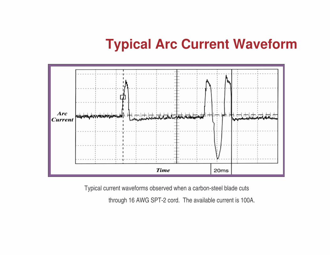
Typical current waveforms observed when a carbon-steel blade cuts
through 16 AWG SPT-2 cord. The available current is 100A.
Typical Arc Current Waveform
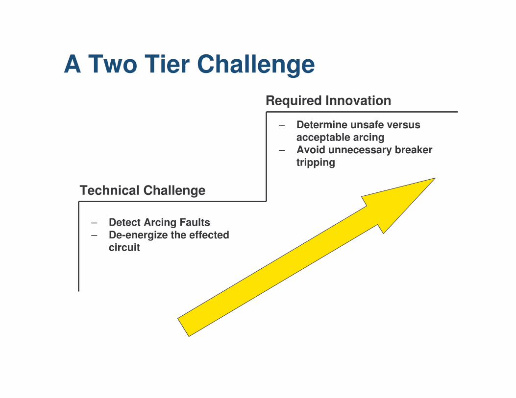
A Two Tier Challenge
– Detect Arcing Faults– De-energize the effected
circuit
– Determine unsafe versus acceptable arcing
– Avoid unnecessary breaker tripping
Technical Challenge
Required Innovation
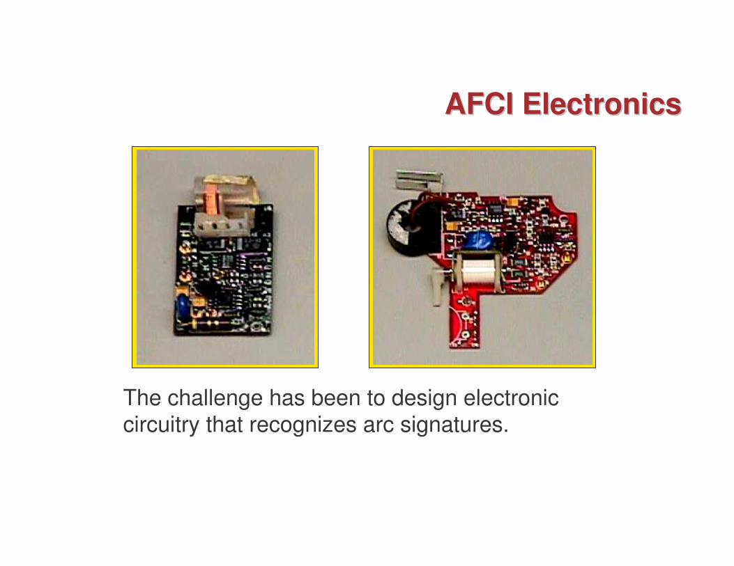
AFCI ElectronicsAFCI Electronics
The challenge has been to design electronic circuitry that recognizes arc signatures.
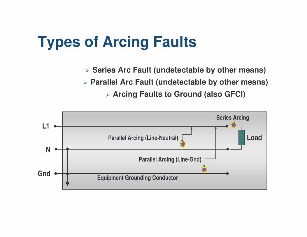
Types of Arcing Faults
� Series Arc Fault (undetectable by other means)� Parallel Arc Fault (undetectable by other means)
� Arcing Faults to Ground (also GFCI)
LoadL1
N
Gnd Equipment Grounding Conductor
Parallel Arcing (Line-Neutral)
Parallel Arcing (Line-Gnd)
Series Arcing
Arc Fault Demo

Questions?