BRAKE SYSTEM, H A - 631 T 183446 - Kress Corporation · 5/20/09 1 FS183446_631HydTractorBrakes_E...
13
5/20/09 1 FS183446_631HydTractorBrakes_E BRAKE SYSTEM, HYDRAULICALLY ACTUATED - 631 T RACTOR 183446 631 Cat Tractors with standard shoe/drum brakes Kress Corporation modifies the Caterpillar tractor air actuated shoe brake system to a hydraulically actu- ated system. This eliminates the need for an air system on the vehicle. The hydraulic system eliminates the cold weather operating problem of air lines becoming clogged with frozen moisture condensation. The air components are all replaced with hydraulic components. The mechanical portion of the shoe brake re- mains the same having the same slack adjuster and linkage. Retaining these same components keeps the servicing and adjusting of the tractor brakes very close to identical to the standard Cat tractors. MAJOR COMPONENTS OF THE HYDRAULICALLY ACTUATED TRACTOR BRAKE CIRCUIT Note: The numbers in parenthesis correlate to image on the next page and also on the foldout schematic page at the rear of this document. • Service Brake Valve, Front (20) • Service Brake Valve, Rear (19) • Brake Accumulator (25) (pre- charged to 720 psi - dry nitrogen [N 2 ]) • Tractor Park/Service Brake Actuator (13) • Tractor Park/Service Brakes (14) • Carrier Service Brakes (17) • Brake Light Pressure Switch (18) (175 psi actuation) • Pump Outlet Pressure Trans- ducer (21) • Park Brake PSI Dump Valve (28) • Brake Manifold 1. Park Brake Pressure Reducing Valve (2) 200 psi (1379 kPa) 2. Park Brake Relief Valve (10) 300 psi (2068 kPa) 3. Service Brake Relief Valve (11) 1050 psi (7239 kPa) 4. Service Brake Pressure Switch (16) (175 psi actuation) 5. Directional Valve (6) (used to release Park Brake when Service Brakes are applied) 6. Park Brake Solenoid Valves (4 & 5) (used to control flow to and from Park Brakes) 7. Test Port 1 & 3 (26 & 27) (used to check pump output pressure) 8. Test Port 2 (15) (used to check pressure to tractor service brake actuators) 9. Test Port 4 (7) (used to check pressure from park brake solenoid valves 4 & 5) 10. Test Port 5 (12) (used to check pressure to park brake actuators) 11. Needle Valve (24) (closed for normal operation - used to relieve accumulator pressure) 12. Needle Valve (3) (closed for normal operation - used to relieve park brake pressure) 13. Needle Valve (8) (open for normal operation - used to close and check park brake reducing valve pressure setting at TP 4)
Transcript of BRAKE SYSTEM, H A - 631 T 183446 - Kress Corporation · 5/20/09 1 FS183446_631HydTractorBrakes_E...

5/20/09 1 FS183446_631HydTractorBrakes_E
BRAKE SYSTEM, HYDRAULICALLY ACTUATED - 631 TRACTOR 183446631 Cat Tractors with standard shoe/drum brakes
Kress Corporation modifies the Caterpillar tractor air actuated shoe brake system to a hydraulically actu-ated system. This eliminates the need for an air system on the vehicle. The hydraulic system eliminatesthe cold weather operating problem of air lines becoming clogged with frozen moisture condensation. Theair components are all replaced with hydraulic components. The mechanical portion of the shoe brake re-mains the same having the same slack adjuster and linkage. Retaining these same components keeps theservicing and adjusting of the tractor brakes very close to identical to the standard Cat tractors.
MAJOR COMPONENTS OF THE HYDRAULICALLY ACTUATED TRACTOR BRAKE CIRCUITNote: The numbers in parenthesis correlate to image on the next page and also on the foldout schematic page at therear of this document.
• Service Brake Valve, Front (20)• Service Brake Valve, Rear (19)• Brake Accumulator (25) (pre-
charged to 720 psi - dry nitrogen[N2])
• Tractor Park/Service BrakeActuator (13)
• Tractor Park/Service Brakes (14)• Carrier Service Brakes (17)• Brake Light Pressure Switch (18)
(175 psi actuation)• Pump Outlet Pressure Trans-
ducer (21)• Park Brake PSI Dump Valve (28)• Brake Manifold
1. Park Brake PressureReducing Valve (2) 200psi (1379 kPa)
2. Park Brake Relief Valve(10) 300 psi (2068 kPa)
3. Service Brake ReliefValve (11) 1050 psi(7239 kPa)
4. Service Brake Pressure Switch (16) (175 psi actuation)5. Directional Valve (6) (used to release Park Brake when Service Brakes are applied)6. Park Brake Solenoid Valves (4 & 5) (used to control flow to and from Park Brakes)7. Test Port 1 & 3 (26 & 27) (used to check pump output pressure)8. Test Port 2 (15) (used to check pressure to tractor service brake actuators)9. Test Port 4 (7) (used to check pressure from park brake solenoid valves 4 & 5)10. Test Port 5 (12) (used to check pressure to park brake actuators)11. Needle Valve (24) (closed for normal operation - used to relieve accumulator pressure)12. Needle Valve (3) (closed for normal operation - used to relieve park brake pressure)13. Needle Valve (8) (open for normal operation - used to close and check park brake reducing
valve pressure setting at TP 4)

5/20/09 2 FS183446_631HydTractorBrakes_E
Brake Manifold located on top of transmission
OPERATIONThe explanation of the hydraulically operated 631G tractor brakes will be covered in three key areas of operation.
• High Pressure Fluid Circuit• Park Brake Circuit• Service Brake Circuit
HIGH PRESSURE FLUID CIRCUITUpon engine startup, the constant pressure piston pump (same as cushion hitch pump) flows fluid to thePall filter (1) at the rate of 9 gpm. This pump is normally set to approximately 2300 psi (15858 kPa). ThePall filter has a 50 psid bypass valve if the 3 micron element becomes clogged. Fluid from the filter flowsto the Brake Manifold that is mounted on top of the transmission.
The fluid from the constant pressure pump can also go to additional circuits besides the brakecircuit, such as the cushion hitch circuit and other optional circuits depending on vehicle model and config-uration.
The Brake Manifold disperses fluid to several hydraulic components including the Brake Accumulator(25), the pressure relieving Needle Valve (24), the Park Brake Pressure Reducing Valve (2), the 3000 psiPressure Transducer (21) and the Service Brake Pedals (19 & 20) in the Operator’s Cab.

5/20/09 3 FS183446_631HydTractorBrakes_E
BRAKE ACCUMULATOR
The 4 gallon hydraulic brake accumulator is used to store fluid under pressureto ensure adequate operating fluid for the park and service brake circuits. Thisaccumulator mounted along side the cushion hitch accumulator will also helpprotect the circuit from pressure spikes if they were to occur. Precharge thisaccumulator with dry nitrogen (N2) to 720 psi (4964 kPa) will all hydraulicpressure relieved by opening the relieving needle valve (24).
ACCUMULATOR TESTING
• Before testing the accumulator first ensure the nitrogen precharge is correctas stated above and chock blocks are placed to prevent vehicle movement.
• Release the Park Brake and start the engine to build maximum accumulatorhydraulic pressure. Check the pressure at Test Port 1 or 3 (26 or 27). Shouldbe approx. 2300 psi.
• Shut off the engine and repeatedly apply the service brakes. The servicebrakes should apply a minimum of 6 times with a minimum of 800 psiremaining in the accumulator circuit. If this cannot be obtained determinethe cause and repair as necessary.
• Repeat this test weekly.
RELIEVING NEEDLE VALVEThe accumulator pressure relieving needle valve (24) is used to relieve anypressure present in the high pressure supply circuit to the hydraulic tank. Thisneedle valve is to be open when precharging the Brake Accumulator andwhenever any lines are to be disconnected in the park and/or service brake cir-cuits. This needle valve is to be closed for normal vehicle operation.
PARK BRAKE PRESSURE REDUCING VALVEThe park brake pressure reducing valve (2) receives approximately 2300 psifluid and reduces it to 200 psi (1379 kPa) for use in the Park Brake circuit.This valve is adjustable. To check the output pressure of this valve attach apressure gauge to test port TP4 (7) and close the needle valve (8) in the parkbrake circuit. Actuate the Park Brake control to release the Park Brakes andcheck the reading on the test gauge. Adjust as necessary to obtain a 200 psi(1379 kPa) reading. Lock the adjustment screw and open the needle valve (8).Remove the test gauge.
3000 PSI PRESSURE TRANSDUCERThe pressure transducer (21) converts the input fluid pressure to an electricalsignal that can be understood by the vehicle’s electrical system so the pressurecan be read on the screen in the cab. The transducer is shown at the right. It isscrewed into the small manifold located under the cab by the front brake pedal(20).
BRAKE PEDALSThe hydraulic brake pedals are located in the cab floor just to the right of the steering column (shown atright). The hydraulic valve portion of the brake pedal is below floor level where hoses can be con-nected outside the cabin as shown at right with the front brake pedal valve (20).
5/20/09 4 FS183446_631HydTractorBrakes_E
PARK BRAKE CIRCUIT
The Park Brake circuit receives operating fluid via the Pressure Reducing Valve (2) which reduces the2300 psi (15858 kPa) pump supply to 200 psi (1379 kPa) for use in the park brake circuit. This 200 psi isused to overcome the spring force in the park brake assembly torelease the park brake for vehicle operation.The 200 psi fluid supply is distributed within the brake manifoldto the Pressure Relieving Needle Valve (3), the Directional Valve(6) and the Normally Closed (NC) Park Brake Solenoid Valve (5).
Before servicing the park brakes or discon-necting any lines in the park brake circuit, first shut down theengine and open the Relieving Needle Valve (3) to relieve anypressure in the circuit to the hydraulic tank.
PARK BRAKE PRESSURE RELIEVING NEEDLE VALVEThe pressure relieving needle valve (3) is used in the ParkBrake circuit to be able to relieve any pressure in this circuit tobe relieved to the tank. This allows components in the ParkBrake circuit to be serviced without risk of high pressure fluidescaping. This needle valve is to remain closed (turned inclockwise until snug) during normal vehicle operation.
DIRECTIONAL VALVEThe Directional Valve (6) located below test port TP1 (26) is used to ensure that the Park Brakes are notapplied at the same time that the Service Brakes are applied which could cause mechanical damage tothe brake components.The Directional Valve is hydraulically actuated by a signal from the Service Brake circuit. When thepark brakes are applied and no service brake pressure signal is being received by the directional valve,the directional valve spool is shifted by a spring to allow park brake fluid from the Normally Open(NO) solenoid valve (4) to return to tank. This allows the springs in the park brake assembly to applythe park brake. Park brake pressure supply fluid (200 psi) is blocked by the directional valve fromgoing to the NO solenoid valve (4).When the Service Brakes are applied a pressure signal to the directional valve shifts the directionalvalve spool and the 200 psi park brake fluid is allowed to go to the NO solenoid valve (4). This in turnallows the fluid to continue on to the park brake assembly to overcome spring force and release the parkbrakes at the same time the service brake fluid is applying the service brakes.
NO SOLENOID VALVEThe Normally Open (NO) Solenoid Valve (4) controls fluid flow between the Directional Valve (6) andthe park brake assemblies. This valve is electrically actuated by a switch in the operator’s cab. Whenno signal is being received the spring moves the spool to allow fluid to flow through this valve. Whenan electrical signal is received the spool shifts to allow fluid to flow toward the park brake assemblies,but an internal check valve will not let this fluid flow away from the park brake assemblies.
NC SOLENOID VALVEThe Normally Closed (NC) Solenoid Valve (5) controls fluid flow between the Pressure ReducingValve (2) and the park brake assemblies. This valve is electrically actuated by a switch in the operator’scab. When no signal is being received the spring moves the spool to block fluid flow through this valveto the brake assemblies, but an internal check valve will allow fluid in the brake assemblies to flow backtoward the reducing valve. (When relieving park brake pressure via the relieving needle valve (3) the
5/20/09 5 FS183446_631HydTractorBrakes_E
check valve in this NC Solenoid Valve (5) allows the park brake fluid to pass through and on to the nee-dle valve (3).) When an electrical signal is received the solenoid valve (5) spool shifts to allow fluid toflow toward the park brake assemblies to release the park brakes.
Both the solenoid valves (4, 5) are actuated at the same time to properly control fluid to and from thepark brake assemblies.
PARK BRAKE SHUTOFF NEEDLE VALVE
The park brake shutoff needle valve (8) is to be open (turned fully counterclockwise) during normalvehicle operation to allow fluid to flow to and from the brake assemblies.To check the park brake circuit pressure close the brake shutoff valve (turned fully clockwise),attach a pressure gauge to test port TP4 (7) and actuate the cab control to release the park brake. Areading of 200 psi (1379 kPa) should be seen when the engine is running. If not, adjust the pressurereducing valve (2) to obtain this pressure.If the vehicle is disabled and the park brakes need to be released, then close the shutoff valve (8)and attach a 200 psi (1379 kPa) pressure supply to test port TP5 (12). If there are no leaks or mechani-cal failures in the park brake system, then the park brakes should release. (See “Towing” for additionalinformation)
The Park Brake Relief Valve (10) is in the circuit to protect overpressuring of the brakecomponents. This relief valve is factory set at 300 psi (2068 kPa).
PARK BRAKE PRESSURE SWITCH
The Park Brake Pressure Switch (9) is factory set to actuate at 175 psi (1207 kPa). When 200 psi (1379kPa) pressure is present in the park brake circuit to release the park brakes, the switch contacts will beopen. When the pressure is relieved in the park brake circuit to apply the park brakes, the switch con-tacts will be closed and the indicator light in the cab dash will be illuminated to alert the operator.
PARK BRAKE PSI DUMP VALVE
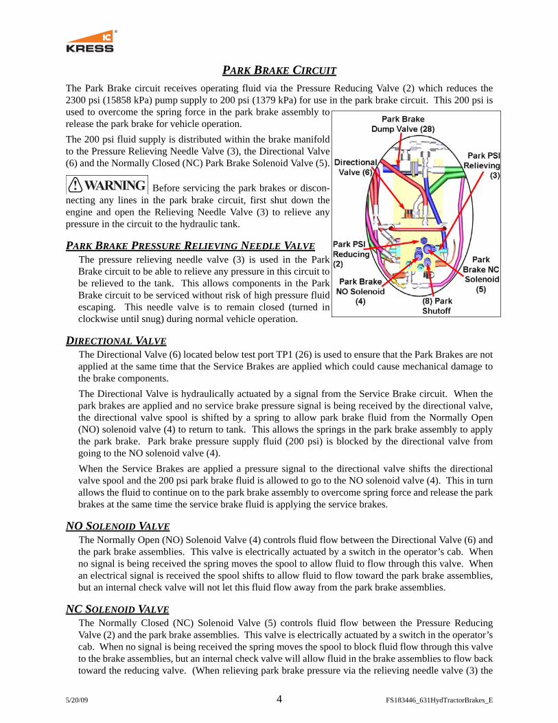
The Park Brake PSI Dump Valve (28)is used to ensure the fluid in the parkchamber of the brake actuatorcylinders will quickly dump (drain)back to the hydraulic tank. Thiselectrically actuated poppet valve isnormally open (NO) to tank andreceives an electric signal wheneverthe park brake is to be released. Thepark brake is released for normalvehicle operation and also wheneverthe service brakes are applied. Theillustration at right shows the parkbrake PSI dump valve and theconnecting lines. The blue lines arepark brake release fluid from theBrake Manifold to the BrakeActuation Cylinders and the greenline is fluid returning to the pump suction line.

5/20/09 6 FS183446_631HydTractorBrakes_E
SERVICE BRAKE CIRCUITS
The Service Brake circuit receives operating fluid via the CabBrake Pedal Valves (19, 20) which proportionally reduce the 2300psi (15858 kPa) pump supply to 820 psi (5654 kPa) for use in thetractor service brake circuit and to 1800 psi (12411 kPa) for use inthe carrier service brake circuit. Two different pressures areneeded because the tractor brakes use a cylinder to actuate the shoebrakes and the carrier brakes are calipers clamping onto a rotor.The brake pedal valves have dual chambers actuated simultane-ously so the front and rear brakes will apply simultaneously.The service brake pressure switch (16) and the retarder pressureswitch (if the machine has a retarder) are in series and go into theTransmission/Chassis ECM. The switch tells the ECM when theservice brakes are being applied. The ECM uses these inputs forthrottle lock and control throttle shifting functions, among otherthings. Another pressure switch (29) monitors the pressure in theservice brake circuit to provide a signal that is used in the electricalcircuit that controls the Park Brake Dump Valve (28).
The park brake pressure switch (9) goes into the Transmission/Chassis ECM also. It splits and goes two places: the carrier parkbrake pressure switch input and the tractor park brake pressureswitch input. The ECM uses these inputs to control the park brakesolenoids. On a standard air brake tractor, there are 3 air pressuresensors (dry tank, wet tank, and pilot tank). These air pressure sen-sors are used to tell the Transmission/Chassis ECM what the actualair pressure is at those 3 places. Based on those values, the follow-ing occurs:
• at around 120 psi, brake indicator OK• at around 70 psi, the EMS service brake indicator will begin to
alarm• at around 43 psi, the Transmission/Chassis ECM will apply the park brakesSince the modified Kress tractors do not have air brake systems, a hydraulic pressure transducer (21) isused to read the brake supply pressure. That signal is sent into the PLC which converts to the 4-20mA sig-nal into a pressure (0-3000 psi). A PWM signal is then generated at the appropriate level to approximatethe 0 to 120 psi PWM signal that the ECM is seeking. Three values are sent:• at greater than 1200 psi hydraulic pressure, the Transmission ECM is told that there is 120 psi (every-
thing is OK)• at 900 to 1200 psi hydraulic pressure, the Transmission ECM is told that there is 70 psi (the EMS brake
indicator will alarm)• at less than 900 psi hydraulic pressure, the Transmission ECM is told that there is 40 psi (the Transmis-
sion ECM will apply the park brake)
Before servicing the brake pedals or disconnecting any lines to the brake pedals, first shutdown the engine and open the Relieving Needle Valve (24) to relieve any pressure in the circuit to thehydraulic tank.

5/20/09 7 FS183446_631HydTractorBrakes_E
FRONT SERVICE BRAKE CIRCUITWhen the service brake pedal is depressed a maximum of 820 psi (5654 kPa) fluid is delivered to the frontshuttle valve (22). The shuttle valve will then direct the fluid on to the front service brake circuit. Thisshuttle is connected to both the front brake pedal (20) and the rear brake pedal (19) so whichever pedal isbeing used will actuate the service brakes. Check application pressure at TP2 on the brake manifold.
The fluid travels to the Directional Valve (6), the Service Brake Relief Valve (11), the Service Brake Pres-sure Switch (16) and to the Service Brake assemblies (13).
DIRECTIONAL VALVEThe fluid to the directional valve (6) located on the brake manifold under TP1 provides signal pressure toactuate the valve to release the Park Brake if it is not already released. This prevents component damagefrom both the Park and Service brakes being applied at the same time.
SERVICE BRAKE RELIEF VALVEThe fluid also goes to the Service Brake Relief Valve (11) which will relieve pressure in the front servicebrake circuit above 1050 psi (7239 kPa) to protect the brake components.
SERVICE BRAKE PRESSURE SWITCHThe Brake Pressure Switch (16) is factory set to actuate at 175 psi (1207 kPa) fluid pressure. This switchprovides a signal to the electrical system when the service brakes are applied.
TEST PORT TP2Test port TP2 (15) located on the brake manifold can be used to check the application pressure of the trac-tor service brakes. Attach a test gauge to this port and apply the service brakes with the engine running.There should be a reading of 820 psi (5654 kPa) when the service brake pedal is fully depressed.

5/20/09 8 FS183446_631HydTractorBrakes_E
BRAKE ACTUATOR CYLINDERThe brake actuator cylinder shown at right performs the functionsof both the Park Brake and the Service Brake.The Park Brake Piston (yellow) and associated tube (also yellow)around the cylinder rod are pushed downward by the Park BrakeApplication Spring (yellow) which pushes the cylinder rod down toapply the tractor’s shoe brakes. (see Figure 1 at the right)To release the Park Brake, fluid (blue) is introduced under the parkbrake piston which forces the piston up compressing the park brakespring. At the same time the Service Brake Retracting spring isforced up which pushes the Service Brake Piston and attached cyl-inder rod to release the tractor’s shoe brakes.To apply the Service Brakes, fluid (brown) is introduced on top ofthe service brake piston (green) which forces the piston down andthe attached cylinder rod to apply the tractor’s shoe brakes. (seeFigure 2 below)When the service brake actuation fluid pres-sure is released, the service brake spring(green) pushes the service brake piston andattached cylinder rod up to release the trac-tor’s shoe brakes.
BRAKE BLEEDERSBleeders are provided to bleed any air thatmight be present in the lines to the park/ser-vice actuator cylinders. These bleeders(shown at right) are located on the inside ofthe RH and LH tractor fenders. (Park towardfront; Service toward rear)Release the Park Brake and open each parkbrake bleeder until an air free stream of fluidis seen and the close the bleeder.Repeat this procedure with the other two bleeders by actuating theservice brakes to purge the air from the lines. Also, when bleedingthe service brakes open the bleeder on the Brake Manifold to bleedany air from those passages.Perform this bleeding procedure during the monthly testing of thesebrakes if they have slower than normal response time.
Figure 2Service Brake Applied
Figure 1Park Brake Applied

5/20/09 9 FS183446_631HydTractorBrakes_E
TOWINGIf the vehicle becomes disabled and must be towed, then the spring applied park brakes must be released toallow the wheels to turn.If hydraulic accumulator pressure is still available, then release the park brakes using the control in thecab and be sure to leave the ignition key “on” to keep the park brake fluid from returning to tank. Attacha gauge to TP3 (27) on the brake manifold to check accumulator pressure or view the pressure on themonitor screen in the cab.
If pressure is not available, then use an auxiliary pressure supply. Close the Shutoff Needle Valve (8),turn the ignition key to “on”, actuate the Park Brake control to release the park brake and attach a pressuresupply of clean hydraulic fluid to TP5 (12). The pressure should be 650 psi (4482 kPa). The 800 psi (5516kPa), Park Relief Valve (10) will protect the system from over pressuring.
If an electical failure has occurred, then an auxiliary hydraulic pressure supply can be used to release the Park Brake. • Disconnect the return to tank hose from
the Quick Dump Valve (shown at right), cap the fitting on the valve and plug the hose to prevent leaks.
• Close the Shutoff Needle Valve (8) and attach a pressure supply of clean hydraulic fluid to TP5 (12). The pressure should be 650 psi (4482 kPa). The 800 psi (5516 kPa), Park Relief Valve (10) will protect the system from over pressuring.
If none of the above methods will not release the Park Brake, then adjust the Slack Adjusters to remove the application pressure on the brakes. At that point the yoke pin should be loose.
SLACK ADJUSTERS
The slack adjusters that the brake actuator cylinders con-nect to are standard Caterpillar components and are to beadjusted as stated in the Caterpillar Service Manual forthis tractor. The following was taken from the Caterpil-lar 631G Service manual.
• Measure movement (1) of the slack adjuster at thepin when the brakes are applied. If the movement is64 mm (2.5 inch) or more, adjust the brake.
• Loosen lock bolt (4). Turn adjusting shaft (3) so that shaft (2) turns in the braking direction. Adjustthe shaft in order to limit movement (1) to 41.1 mm (1.62 inch).
• Tighten lock bolt (4).

5/20/09 10 FS183446_631HydTractorBrakes_E
ADJUSTABLE COMPONENTS OF THE BRAKE SYSTEM• Park Brake Pressure Reducing Valve (2): 200 psi (1379 kPa)• Accumulator (25) Nitrogen (N2) Precharge: 720 psi (4964 kPa)• Cushion Hitch CP Piston Pump: 2300 psi (15858 kPa)
NON-ADJUSTABLE COMPONENTS OF THE BRAKE SYSTEM• Park Brake Relief Valve (10) (factory set)• Service Brake Relief Valve (11) (factory set)• Brake Pedal Valves (19, 20) (factory set)
PORTS TO TEST PRESSURES• TP1 (26) (pump supply pressure to system)• TP2 (15) (Service delivery pressure)• TP3 (27) (pump supply pressure to system)• TP4 (7) (Park Brake psi between solenoid valves (4, 5) and
Park Brake Shutoff Needle Valve (8)• TP5 (12) (Park Brake psi between Park Brakes (13, 14) and
Park Brake Shutoff Needle Valve (8)
PRESSURE TRANSDUCER• 3000 psi Pressure Transducer (21)
PRESSURE SWITCHES• Brake Light Switch (18) (175 psi) (optional)• Service Brake Pressure Switch (16) (175 psi)• Park Brake Pressure Switch (9) (175 psi)• Service Brake PSI for Park Dump Circuit (29)
MANIFOLD NEEDLE VALVES• Park Pressure Relieving Needle Valve (3) (To be closed dur-
ing normal operation. During maintenance it can be openedto relieve pressure to apply the park brake or for servicing thecircuit.)
• Park Brake Shutoff Needle Valve (8) (To be open during nor-mal operation. During maintenance it can be closed to checkand/or set the park brake psi reducing valve.)
• Accumulator Pressure Relieving Needle Valve (24) (To beclosed during normal operation. During maintenance it canbe opened to relieve pump & accumulator pressure for ser-vicing the manifold and circuit.)

5/20/09 11 FS183446_631HydTractorBrakes_E
TROUBLESHOOTING INFORMATION
The chart below will provide troubleshooting information only for the modified Caterpillar 631 hydrau-lic tractor brake circuits by giving problem symptoms, areas to check and possible solutions to the prob-lems. The numbers in parenthesis (4) are shown in the illustrations on the previous pages and also in theschematic at the end of this document. Information on carrier brakes is in separate documents.
The fluid from the constant pressure pump can also go to additional circuits besides thebrake circuit, such as the cushion hitch circuit and other optional circuits depending on vehicle model andconfiguration. If pressure loss is being experienced, ensure the other circuits from the CP pump are func-tioning properly also.
SYMPTOMS DIAGNOSTIC CHECKS SOLUTION
Park BrakesPARK BRAKE WILLNOT RELEASE
A. Does test port TP1 show 2300 psi (15858 kPa) when engine is running?
If yes, this indicates the pump is working so go to next check.If no, repair or replace the pump and retest.
B. Does test port TP5 (12) show 200 psi (1379 kPa) when the park brake switch is actuated in the cab?
If no, go to next check.If yes, then check for line leaks to the tractor brake cylinders, mechanical failures in the actua-tor cylinders and proper adjust-ment of the slack adjusters.
C. Is the shutoff needle valve (8) closed (turned fully clockwise)? It should be open.
If yes, then open the valve and retest.If no, then go to next check.
D. Are all three park brake solenoids (4, 5, 28) receiving a 24 volt signal when the park brake switch is actuat-ed?
If yes, go to next check.If no, determine the cause, repair as necessary and retest.
E. Close the shutoff needle valve (8) and check at test port TP4 (7) to see if 200 psi (1379 kPa) when the park brake switch is actuated in the cab
If no, go to next check.If yes, then check the park brake relief valve (10) to see if fluid is bypassing below 300 psi.Also, check the dump valve (28) to see if it is bypassing fluid back to tank.
F. Is the relieving needle valve (3) closed (turned fully clockwise)?
If yes, go to next check.If no, close the valve and retest.

5/20/09 12 FS183446_631HydTractorBrakes_E
G. Is the pressure reducing valve (2) allowing fluid to flow to the solenoid valves (4, 5)? Check this first to ensure the accumulator is charged at TP1 with the engine shut off. Then with the engine off, open the park relieving needle valve (3) and listen for fluid flowing back through the needle valve. Is the sound of fluid flowing back to tank present with the needle valve open?
If no, then check, repair, adjust or replace the pressure reducing valve (2).If yes, then check, repair or re-place the solenoid valves (4, 5, 28) because either the NC valve (5) is not opening or one of the NO valves (4, 28) is not closing, either of which will not allow pressure build to release the park brake.
PARK BRAKE WILL NOT APPLY
A. Do the service brakes function properly?
If yes, go to next check.If no, then check the slack ad-justers for proper adjustment.
B. Is the shutoff needle valve (8) closed? It should be open.
If yes, then fully open it by turn-ing fully counter-clockwise and retest.If no, then go to next check.
C. With the engine shut off, open the relieving needle valve (3). Did the park brakes apply?
If no or applied slowly, then check the directional valve (6) as it may be stuck in the actuated position allowing park brake flu-id to the actuation cylinders.If yes, but only after the accu-mulator pressure was depleted, then check the NC solenoid valve (5) because it may be stuck open. Repair or replace as nec-essary.
Service BrakesSERVICE BRAKES WILL NOT APPLY
A. Does test port TP1 show 2300 psi (15858 kPa) when engine is running?
If yes, this indicates the pump is working so go to next check.If no, then check to ensure the relieving needle valve (24) is closed before repairing or replac-ing the pump. If the needle valve was open, close it and retest.
B. Does one of the brake pedals (front or rear) work, but not the oth-er?
If yes, then check the service shuttle valve (22) and the non-functioning brake pedal valve for damage and/or contamination. Repair or replace as necessary.If neither pedal functions, then go to next check.
SYMPTOMS DIAGNOSTIC CHECKS SOLUTION

5/20/09 13 FS183446_631HydTractorBrakes_E
C. Do the service brakes on the carri-er work, but not the tractor with one of the pedals?
If yes, then repair or replace the pedal valve (19, 20) that is not functioning.If no, neither pedal will actuate the tractor brakes, then go to the next check.
D. With one of the brake pedals fully depressed, is approximately 820 psi (5654 kPa) present at test port TP2 (15)?
If yes, then check for mechanical damage to the brake actuator cyl-inders and proper slack adjuster adjustment. Repair as necessary.If no, then check the service brake relief valve (11) for dam-ages. Repair, replace or adjust as necessary and retest.
SERVICE BRAKES WILL NOT RELEASE
A. Is the Park Brake switch in the ac-tuated position?
No, then go to next check.Yes, then deactuate the Park Brakes and retest.
B. Is hydraulic pressure present at test port TP2 (15)?
If no, then check for proper slack adjuster adjustment and if that is correct, the check the actuator cylinders for damages. Repair or replace as necessary.If yes, then one of the brake ped-als is not fully returning or its valve is damaged and letting flu-id bypass. Repair or replace as necessary.
SYMPTOMS DIAGNOSTIC CHECKS SOLUTION