BRACING CONFIGURATION IN EARTHQUAKE RESISTANT...
14
COMPDYN 2011 III ECCOMAS Thematic Conference on Computational Methods in Structural Dynamics and Earthquake Engineering M. Papadrakakis, M. Fragiadakis, V. Plevris (eds.) Corfu, Greece, 25–28 May 2011 BRACING CONFIGURATION IN EARTHQUAKE RESISTANT STRUCTURE Tonia Sophocleous 1 and Marios C. Phocas 2 1,2 Department of Architecture, Faculty of Engineering, University of Cyprus 75 Kallipoleos Str., P.O.Box 20537, 1678 Nicosia, Cyprus [email protected], [email protected] Keywords: Dual Structures, Hysteretic Dampers, Cable Bracing, Energy Dissipation Systems. Abstract. Technological advances in the seismic design of energy dissipation systems raise the issue of the codes dominated capacity design of structures. Building code requirements that describe the dynamic behavior, modeling and analysis of structures with different types of energy dissipation systems are currently under review. A new seismic design approach, de- scribed in the current paper, adds to the current research activities of the authors on passive- ly controlled systems with integrated hysteretic damper and cable bracings. The control system considers at first place the effect of added stiffness when conventional bracings are added to structural frames that are necessary for the integration of the damping devices. An increase in the systems stiffness may result to a reduction of the peak displacement, i.e. peak pseudo-acceleration, and thus to an increase of the shear forces. In addition, an increase in damping can significantly influence the response of elastic and inelastic systems. The new system proposed aims at both, energy dissipation and damage control. It consists of an energy dissipation device and a portal cable bracing mechanism with a kinetic closed loop, working only in tension. The closed bracing mechanism does not practically affect the initial stiffness of the system, i.e. the concept relies on two completely “separate” systems: a primary for the vertical- and wind loads and a secondary for the earthquake loads. Analysis model considera- tions for describing the physical behavior of the system in computational language are pre- sented, by incorporating the SAP2000 program, revealing step by step the procedure followed for the resulting desired dynamic performance. Based on the energy balanced equation at each time-step, the hysteretic energy dissipation demand is reduced when the supplemental damping system is utilized. An Effective Toughness Index, in accordance to the time- dependence of the hysteretic energy dissipation is proposed to characterize the portions of the input energy dissipated by the control system. The predominant parameters that characterize the system’s seismic behavior are derived on the basis of a parametric analysis under selected international strong ground motions. Finally the systems behavior is verified in respect to the mechanical properties of the control elements under the action of ten selected earthquake ex- citations of the Greek-Mediterranean region. The parametric analyses of the system’s seismic behavior conclude with a proposed preliminary design methodology for the passively con- trolled SDOF models.
Transcript of BRACING CONFIGURATION IN EARTHQUAKE RESISTANT...

COMPDYN 2011 III ECCOMAS Thematic Conference on
Computational Methods in Structural Dynamics and Earthquake Engineering M. Papadrakakis, M. Fragiadakis, V. Plevris (eds.)
Corfu, Greece, 25–28 May 2011
BRACING CONFIGURATION IN EARTHQUAKE RESISTANT
STRUCTURE
Tonia Sophocleous1 and Marios C. Phocas
2
1,2 Department of Architecture, Faculty of Engineering, University of Cyprus 75 Kallipoleos Str., P.O.Box 20537, 1678 Nicosia, Cyprus
[email protected], [email protected]
Keywords: Dual Structures, Hysteretic Dampers, Cable Bracing, Energy Dissipation Systems.
Abstract. Technological advances in the seismic design of energy dissipation systems raise
the issue of the codes dominated capacity design of structures. Building code requirements
that describe the dynamic behavior, modeling and analysis of structures with different types
of energy dissipation systems are currently under review. A new seismic design approach, de-
scribed in the current paper, adds to the current research activities of the authors on passive-
ly controlled systems with integrated hysteretic damper and cable bracings. The control
system considers at first place the effect of added stiffness when conventional bracings are
added to structural frames that are necessary for the integration of the damping devices. An
increase in the systems stiffness may result to a reduction of the peak displacement, i.e. peak
pseudo-acceleration, and thus to an increase of the shear forces. In addition, an increase in
damping can significantly influence the response of elastic and inelastic systems. The new
system proposed aims at both, energy dissipation and damage control. It consists of an energy
dissipation device and a portal cable bracing mechanism with a kinetic closed loop, working
only in tension. The closed bracing mechanism does not practically affect the initial stiffness
of the system, i.e. the concept relies on two completely “separate” systems: a primary for the
vertical- and wind loads and a secondary for the earthquake loads. Analysis model considera-
tions for describing the physical behavior of the system in computational language are pre-
sented, by incorporating the SAP2000 program, revealing step by step the procedure followed
for the resulting desired dynamic performance. Based on the energy balanced equation at
each time-step, the hysteretic energy dissipation demand is reduced when the supplemental
damping system is utilized. An Effective Toughness Index, in accordance to the time-
dependence of the hysteretic energy dissipation is proposed to characterize the portions of the
input energy dissipated by the control system. The predominant parameters that characterize
the system’s seismic behavior are derived on the basis of a parametric analysis under selected
international strong ground motions. Finally the systems behavior is verified in respect to the
mechanical properties of the control elements under the action of ten selected earthquake ex-
citations of the Greek-Mediterranean region. The parametric analyses of the system’s seismic
behavior conclude with a proposed preliminary design methodology for the passively con-
trolled SDOF models.

Tonia Sophocleous and Marios C. Phocas
2
1 INTRODUCTION
The design of frame structures with additional control members for earthquake resistance refers primarily to the need for the primary systems to exhibit essentially a linear behavior under seismic actions [1]. A reduction of the energy dissipation demand on primary structural systems was successfully aimed at by a number of researchers [2]. Passive metallic yielding, viscoelastic and viscous damping devices may be added to frame structures to dissipate input energy during an earthquake and to substantially reduce or eliminate damage to the gravity-load-resisting frames. ADAS and TADAS are well known examples, available for both, new seismic resisting designs and retrofit of frame buildings [3]. Some types of supplemental damping can substantially change the force-displacement response of the structure by adding strength and stiffness. Stiff bracings in such energy dissipation systems (EDS) reduce inter-story drifts, but they produce high accelerations; on the other hand more flexible slender brac-ings, such as cables or tension-only rods, attract smaller forces and tend to reduce floor accelerations Additionally the effective added damping benefit of EDS is shadowed by the coupling effect of the primary- and control system, due to the unavoidable stiffness increase of the former [4-6].
The research inquiry of utilizing the performance of mild steel in terms of strength, flexi-bility and minimal weight, coupled with the need of a smooth, non-coupled operation under dynamic excitations has led to the development of Adaptable Dual Control Structures (ADCS) [7-10]. The basis of the design philosophy of the systems comprises the component defor-mation capacity that characterizes the performance and damage of the system. The cable brac-ing mechanism with closed loop and the integrated hysteretic damper that forms within moment resisting frames an ADCS enables the primary system to respond elastically under load combinations of static- (gravity and equivalent static wind) and dynamic (moderate, ex-tremely irregular base excitations) actions. The design objective for the proposed systems is to “dual” the response performance between the primary frame and the added control members
that practically do not affect the elastic response of the main structure, but concentrate all the damage to the replaceable damper. A number of critical configurations have been conceived by the authors [7, 8], of which one is presented in the current paper.
Following the construction design of ADCS, the design parameters have been defined through a parametric analysis that involves 342 combinations of both geometrical and me-chanical system properties, subjected to three international strong earthquake motions: El Centro 1940, Kobe 1995 and Northridge 1994. The range of the design application is clearly stated in terms of both, the characteristic period and the limiting lateral displacements of the passively controlled system. The designer may target to a desirable performance by defining an effective energy deformation index (EEDI). Predominant design parameters for character-izing the ADCS’s response are revealed through the parametric analysis, defined as a function of the non-linear link’s elastic stiffness and yield force, the Damper Ratio (DR). ADCS’s ef-fective response behavior in terms of energy dissipation, minimal displacements and practi-cally non-coupled performance between the frame and the added dissipaters is verified under ten selected earthquake records of the Greek-Mediterranean seismic zone.
2 BRACING CONFIGURATION
Prestressed tensile bracings are used as tension-only members in ADCS. In common appli-cations, not only the low stiffness of cables, but also the nature of hinged frame construction, makes these elements vulnerable to lateral and vertical movements. Through respective modi-fication of their geometry the elements initiate a static non-linear response to the induced strong ground movements at their base and adapt to this by activating a kinetic mechanism,

Tonia Sophocleous and Marios C. Phocas
3
Figure 1. The displacement is transferred at the optimal joint where the hysteretic device is connected at its one end, while its other end is fixed at the primary beam and follows the lat-eral frame’s movement in every cycle. Tuning of both, the mechanical and geometric charac-teristics of the composed members with the respective primary frame may lead to high portions of energy dissipation and therefore add damping to the system. The control system is also responsible for the system’s relative displacements and the avoidance of any significant base shear increase. Due to the characteristic configuration, ideally the reactions from the added elements to the primary frame are neutralized. The optimization of the damper-bracing mechanism involves tuning between the stiffness, the yield force and the relative displace-ment that the hysteretic damper develops to the tension-only bracings and in extent, to the primary frame, so that the energy flow in terms of hysteresis for the damper and the elastic strain energy for the cable restraints and the primary frame are effective.
Figure 1: Frame Configuration for ADCS, S1.
2.1 Connection Design
The construction technique developed for ADCS aims at achieving among others the nec-essary stiffness on the flexible members, their prestressing and the stabilization of the system. When ADCS proposed systems are subjected to earthquake loads a kinematic mechanism is activated. This is made possible through eccentrically placed discs at the main joint region that rotate and drag along the horizontal bracing member that induces relative deformations between the damper’s ends, defined as the Interdamper Drift, Figure 2. The damper is de-signed to yield in its inelastic region and dissipate energy. When the lateral translation on the frame changes to the opposite sense, the procedure is repeated. At the end of a complete cycle, all tension-only members are stretched to their maximum potential. ADCS utilize the previ-ously established knowledge on the effectiveness of the yielding metallic dampers, ADAS and TADAS that have already been confirmed through ample tests and analytical studies [2, 3]. ADCS design introduces slightly modified shape sections of similar dampers. The damp-er’s section is selected to result in uniform bending curvature over the section’s height. The
transverse force applied at the end of each plate causes uniformly bending curvature and all section lines reach their maximum yielding potential at the same time.

Tonia Sophocleous and Marios C. Phocas
4
Figure 2: Connections’ Design for ADCS, S1.
ADCS response for the desirable level of seismic protection depends primarily on two main factors:
1. The effective values of the relative stiffness of the primary frame, the bracing and the hysteretic device at the target displacement that leads to the selection of the design stiffness of the damper, kd, given by the following equation:
3
bd
h
EI)b/a2(nk
(1)
where kd is the initial elastic stiffness of the hysteretic damper, Ib, the second moment of area at the top of the steel plates used as hysteretic damper, h is the height, b is the upper width (fixed to the beam) and a is the lower width (connected to the bracing member), E= 2.1x10⁴ kN/cm2
, ρ= 78.5 kΝ/m3 for S235 mild steel material of the damper plates, as
shown in parallel arrangement in Figure 2. 2. The load, at which the damper yields and dissipates energy through its inelastic yielding deformation, given by the following equation:
h4
btnfP
3y
y (2)
where fy is the yield stress (fy= 24 kN/cm² for S235), and t is the thickness of each plate.
3 PRELIMINARY INVESTIGATION
3.1 Frame Modeling
The finite element analysis of ADCS relies on a simplified model, whereas non-linearity is only addressed for the hysteretic damper, i.e. the non-linear link. The dynamic behavior of the simulated ADCS was examined using the FE program SAP2000. A typical geometry was as-signed for the ideal model of the steel moment resisting frame: a 6.0 m long beam and 4.5 m high column members in a 2D representation model. The bracing members were modeled as tension-only elements and a suitable pretension stress was applied to each of them. The ADCS’s tendons’ geometry was carefully drawn for the software model to represent the con-figuration with high accuracy. The disc was modeled as a composition of three short frame members, assigned with large stiffness values to represent the real property of a shaft. The preliminary analysis was completed for a number of combinations of characteristic design variables. IPBl500 sections were assigned for the columns and IPBl550 for the beam. The di-mensioning of the members was based on Eurocode 3, having assumed a static vertical load of 1200 kN and a static equivalent wind load of 15 kN. A range of diameters between dc= 15 mm and dc= 40 mm was tested in the investigation. The geometry of the steel plates varied in the parametric analysis, as follows: h= 15, 20, 25, 30, 35, 40 cm; n= 6, 8, 10; b= 4, 5, 6 cm; t=

Tonia Sophocleous and Marios C. Phocas
5
8, 10, 11, 12, 13, 14, 15, 16, 18, 20 mm. The calculated initial stiffness for the damper varied between 450 kN/m < kd < 24200 kN/m and the yield force, between 3.5 kN < Py < 43 kN.
3.2 Input Seismic Records
The system’s displacement depends directly on the amplitude of the ground motion; alt-hough the damper’s dynamic properties are defined by the designer. In order to identify the parameters that dominate the response of ADCS, the configuration presented in Figure 1, was analytically tested under the records of El Centro, Kobe and Northridge as described in Table 1.
Record Mw PGA (g) Duration (s) Scale factor El Centro 1940 6.9 0.348 53.76 2.871 Kobe 1995 6.9 0.821 48.00 1.218 Northridge 1994 6.7 0.604 30.00 1.655
Table 1: International Seismic Input Records.
The predominant design parameters of ADCS are the stiffness of the damper kd and the yield load Py, as given by equations (1) and (2). Based on the analysis results, the Damper Ra-tio (DR) that describes the response of ADCS as a function of its stiffness and yield force is introduced, as follows:
y
dDR
Pk
(3)
where kd is the damper’s stiffness and Py is the yield load of the hysteretic device, measured in 1/m units. A range between 55 1/m < DR < 780 1/m values was examined to construct the parametric analysis results diagram.
3.3 Modeling of the Non-Linear Behavior
Hysteretic dampers may exhibit a bilinear or trilinear hysteresis, an elasto-plastic or rigid-plastic behavior, which can be captured with the structural analysis software SAP2000. The damper used in ADCS was modeled as a non-linear link element. The damper’s force-deformation relationship for a respective degree of freedom, corresponding to shear, was modeled to follow the hysteretic model described as Wen plasticity property type of uniaxial deformation. Several hysteresis models were tested analytically to represent the damping fea-ture of the composed damper. The Wen-Plasticity model was finally adopted and the results were calculated based on this characteristic hysteresis model, mathematically described as follows:
zyield)ratio1(dkratiof (4)
where f is the force and d, the induced displacement, k is the elastic spring constant, i.e. initial stiffness, “yield” is the yield force, “ratio” is the specified ratio of the post-yield stiffness to the elastic stiffness, i.e. secondary stiffness ratio, and z is an internal hysteretic variable that evolves according to the following differential equation:
otherwisedor,0zdifz1(dyield
kz
exp
(5)
where “exp” is an exponent greater than or equal to unity (practically about 20), z, a path de-pendency parameter. SAP2000 provides the analytical model shown in equation (4), which
Tonia Sophocleous and Marios C. Phocas
6
represents the hysteretic behavior of the device. During the dynamic motion, inertia forces are activated by all concentrated masses; including the mass distributed on the rigid plates’ sec-tion (md in SAP2000, assigned with a default value of 0.24 kg) for the inertia forces contrib-uted by the damper. The related resistance is given as the integral of the “second moment”
about an axis of all the elements of mass dm, which compose the body of the steel plate used for the added damping, known as “MMI”, Mass Moment of Inertia, RI in SAP2000 and as-signed with a default value of RI= 0.175.
3.4 Parametric Analysis
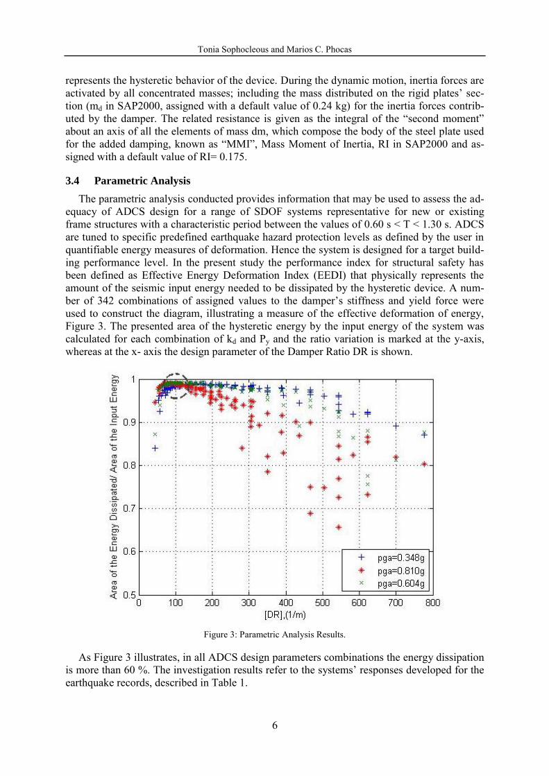
The parametric analysis conducted provides information that may be used to assess the ad-equacy of ADCS design for a range of SDOF systems representative for new or existing frame structures with a characteristic period between the values of 0.60 s < T < 1.30 s. ADCS are tuned to specific predefined earthquake hazard protection levels as defined by the user in quantifiable energy measures of deformation. Hence the system is designed for a target build-ing performance level. In the present study the performance index for structural safety has been defined as Effective Energy Deformation Index (EEDI) that physically represents the amount of the seismic input energy needed to be dissipated by the hysteretic device. A num-ber of 342 combinations of assigned values to the damper’s stiffness and yield force were
used to construct the diagram, illustrating a measure of the effective deformation of energy, Figure 3. The presented area of the hysteretic energy by the input energy of the system was calculated for each combination of kd and Py and the ratio variation is marked at the y-axis, whereas at the x- axis the design parameter of the Damper Ratio DR is shown.
Figure 3: Parametric Analysis Results.
As Figure 3 illustrates, in all ADCS design parameters combinations the energy dissipation is more than 60 %. The investigation results refer to the systems’ responses developed for the earthquake records, described in Table 1.

Tonia Sophocleous and Marios C. Phocas
7
3.5 Preliminary Design
A simplified structural analysis and design procedure may be used to test the reliability of ADCS when under arbitrary seismic input records. The numerical application involves a se-lection of 10 real records in the Mediterranean earthquake prone zone for peak ground accel-erations ranging between 0.10g and 0.50g, time durations, between 10 s and 50 s and different frequency contents, Table 2. PGA Ground Acceleration Record PGA Ground Acceleration Record
0.50g
0.20g
0.33g
0.18g
0.24g
0.15g
0.22g
0.14g
0.21g
0.10g
Table 2: Mediterranean Seismic Input Records.
The following steps are suggested for the design: 1. Select the design earthquake and assign a critical damping coefficient of 0 %. 2. Dimension the primary frame system to resist the gravity and wind load actions, (i.e. 1200 kN vertical and 15 kN lateral), combined with 25% of the static equivalent seismic load according to Eurocode 3. 3. Calculate for the dimensioned SDOF frame, the stiffness property in respect to both, the assigned mass (i.e. gravity load) and the initial estimation of the characteristic period. The period has to be within the suggested range of 0.60 s < T < 1.30 s for the indicated configu-ration. 4. Select the target allowable relative system’s displacement as a percentage of its height and according to the displacement-based analysis (i.e. 1.5 % of the SDOF system’s height). The procedure is based on previously established research results on ADCS response be-havior for the estimation of the initial system’s design parameters [7-11]. The proposed values are adopted for the next step of the design procedure. 5. Calculate the initial stiffness of the tension-only bracings by addressing the suggested factor of 1.65 to the inverse of the tendons stiffness, i.e. 1/kb, kb: bracing’s stiffness [11]. 6. Determine the bracing’s configuration under P-Delta load combinations so that it main-tains its configuration without becoming slack after the structure is loaded. In the present application example, the cables are assigned with a diameter of dc= 20 mm, with E= 1.6x10⁴ kN/cm2 and fy= 79.5 kN/cm2.

Tonia Sophocleous and Marios C. Phocas
8
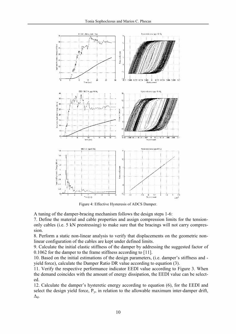
3.6 Effective Yielding
In order for the yielding of the non-linear link to be effective, the kinetic response of the cable-restraints should be verified to be tuned to the hysteretic performance of the damper for an arbitrary case of selected design parameters as shown in Figure 4. The diagrams present for each one of the seismic inputs the comparison of input and hysteretic energy and the respec-tive hysteresis for the damper with characteristics of h= 15 cm, n= 6, t= 1.2 cm, b= 5 cm, m= 0,24 kg, and a rotational inertia of RI= 0,175.
The resulting hysteresis in the damper is assumed to be equal with the dot product of the damper’s yield force Py and the design Interdamper drift Δd, expressed as folllows:
d
HydyH
EPPE .
(6)

Tonia Sophocleous and Marios C. Phocas
9
Tonia Sophocleous and Marios C. Phocas
10
Figure 4: Effective Hysteresis of ADCS Damper.
A tuning of the damper-bracing mechanism follows the design steps 1-6: 7. Define the material and cable properties and assign compression limits for the tension-only cables (i.e. 5 kN prestressing) to make sure that the bracings will not carry compres-sion. 8. Perform a static non-linear analysis to verify that displacements on the geometric non-linear configuration of the cables are kept under defined limits. 9. Calculate the initial elastic stiffness of the damper by addressing the suggested factor of 0.1062 for the damper to the frame stiffness according to [11]. 10. Based on the initial estimations of the design parameters, (i.e. damper’s stiffness and -yield force), calculate the Damper Ratio DR value according to equation (3). 11. Verify the respective performance indicator EEDI value according to Figure 3. When the demand coincides with the amount of energy dissipation, the EEDI value can be select-ed. 12. Calculate the damper’s hysteretic energy according to equation (6), for the EEDI and select the design yield force, Py, in relation to the allowable maximum inter-damper drift, Δd.

Tonia Sophocleous and Marios C. Phocas
11
The final step of the design procedure involves the dimensioning of the damper according to the system’s response, as this may be characterized through its initial elastic stiffness kd and its yield force Py: 13. According to the selected damper’s yield force and stiffness, select the number and ge-ometry of the damper’s steel plates by using equations (1) and (2).
3.7 Base Shear
The design should verify that the base shear on ADCS is not increased after the addition of the damper-bracing mechanism. Otherwise, the input energy may also increase. In addition to the latter, an increase of the strength demand on the primary frame may become higher than the foundations can carry at the end of the flow of forces circle. As Table 3 shows, there is a decrease of the base shear of the controlled system in 80 % of the cases and an increase in 20 % of the cases that can be neglected because of its small magnitude. According to the nu-merical results of the parametric analysis, the increase of the base shear can be practically ne-glected. An example is shown in Table 3. Record Primary Frame (kN) ADCS: S1 (kN) Aigio 95 (Aigio, 00), 0.50g 1577.00 -1563.00 1427.25 -1415.15 Athens 99 (Sepolia, 00), 0.33g 1978.00 -2048.00 1847.89 -1897.44 Ionian 83 (Argostoli, 900), 0.24g 480.40 -500.30 543.81 -530.99 Kalamata 86 (Kalamata, 00), 0.22g 1270.00 -1278.00 1160.92 -1136.81 Heraklio 84 (Heraklio, 900), 0.21g 1735.00 -1738.00 1282.54 -1323.04 Aigio 90 (Aigio, 900), 0.20g 1361.00 -1361.00 1222.41 -1208.77 Etolia 88 (Valsamata, 900), 0.18g 848.40 -882.90 865.73 -895.40 Killini 88 (Zakinthos, 900), 0.15g 2516.00 -2515.00 2021.72 -2019.67 Preveza 81 (Preveza, 00), 0.14g 2381.00 -2445.00 2302.20 -2285.20 Gulf of Corinth 93 (Nafpaltos, 900), 0.10g 519.10 -372.80 509.17 -357.06
Table 3: Base Shear Results.
3.8 Displacement Control
A range of defined allowable relative displacement limits should be followed for the frame to resist elastically, for the tension-only bracings to avoid compression and for the hysteretic damper to be energized. Table 4 shows the respective analysis results of the primary frame and for the arbitrary selection of ADCS assigned parameter values. A reduction of the re-sponse displacements is found in 80 % of the cases.
Record Primary Frame (cm) ADCS: S1 (cm) Aigio 95 (Aigio, 00), 0.50g 1.92 -1.90 1.75 -1.73 Athens 99 (Sepolia, 00), 0.33g 2.50 -2.42 2.32 -2.27 Ionian 83 (Argostoli, 900), 0.24g 0.63 -0.59 0.65 -0.67 Kalamata 86 (Kalamata, 00), 0.22g 1.54 -1.53 1.37 -1.41 Heraklio 84 (Heraklio, 900), 0.21g 2.12 -2.11 1.62 -1.57 Aigio 90 (Aigio, 900), 0.20g 1.66 -1.66 1.49 -1.51 Etolia 88 (Valsamata, 900), 0.18g 1.07 -1.04 1.09 -1.06 Killini 88 (Zakinthos, 900), 0.15g 3.07 -3.07 2.48 -2.48 Preveza 81 (Preveza, 00), 0.14g 2.98 -2.90 2.80 -2.82 Gulf of Corinth 93 (Nafpaltos, 900), 0.10g 0.46 -0.63 0.45 -0.62

Tonia Sophocleous and Marios C. Phocas
12
Table 4: Relative Displacement Results.
3.9 Interdamper Drift
The effectiveness of the proposed ADCS is based on the relative displacements between its composed members, in particular, the damper’s end points. The displacement is defined as Interdamper Drift, i.e. the relative displacement of the primary frame to the cable bracings. Some respective indicative results for the numerical example analyzed are plotted in Figure 5. The relation between the Interdamper Drift for a given seismic action load and the Effective Energy Dissipation is vital for the optimization procedure of ADCS design.

Tonia Sophocleous and Marios C. Phocas
13
Figure 5: Interdamper Drift.
4 CONCLUSIONS
The application of Adaptable Dual Control Systems that may be designed to supply measura-ble added damping to frame structures through the yielding of an integrated hysteretic damper is proposed in the present paper. The concept refers to a kinetically developed damper-bracing mechanism. A configuration design of tension-only bracings with closed circuit and a hyster-etic damper are investigated under strong earthquakes. In principle the optimization procedure for the best seismic control response of ADCS refers to a good trade-off between the desirable increase in energy dissipation and control of both, base shear and relative displacements, compared to the response of the primary frame without the control mechanism. The leading parameters of the design were traced through a parametric analysis that has been based on 342 combinations of design parameters. New design properties that seemed to govern the design were defined and calculated for each analytical test. The design parameters have been verified in the response behavior of ADCS under the earthquake records of the Greek-Mediterranean seismic zone, significantly different from each other and from the international ones, in their frequency content, time duration and peak ground acceleration characteristics. The benefit of high energy dissipation levels by ADCS has been proven for a broad range of the hysteretic damper’s mechanical and geometrical properties. Additionally, the common concern in pas-sively controlled frame structures, of stiffness increase, or induction of larger displacements, and the limitation of the maximum displacements of the damper-bracing mechanism’s mem-bers proved to be managed satisfactorily in the designs. Ready make diagrams that may be used for further applications are given to assist the procedure for designing structures that may develop an adaptable seismic control response mainly due to the property of “duality” as
it is valid for ADCS.

Tonia Sophocleous and Marios C. Phocas
14
REFERENCES
[1] G.W. Housner, L.A. Bergman, T.K. Caughey, A.G. Chassiakos, R.O. Claus, S.F. Masri, R.E. Skelton, T.T. Soong, Jr. B.F. Spencer, T.P. Yao, Structural Control: Past, Present and Future. Engineering Mechanics, 123(9), pp. 897-971, 1997.
[2] M.D. Symans, F. Charney, M.C. Constantinou, C. Kircher, M.W. Johnson, R.J. McNamara, Energy Dissipation Systems for Seismic Applications: Current Practice and Recent Developments. Structural Engineering, 134(1), pp. 3-21, 2008.
[3] K.C. Tsai, H.W. Chen, C.P. Hong, Y.F. Su, Design of Steel Triangular Plate Energy Absorbers for Seismic-Resistance Construction. Earthquake Spectra, 9, pp. 505-528, 1993.
[4] M. Kurata, R. DesRoches, R.T. Leon, Cable Damper Bracing for Partial Seismic Reha-bilitation. 14th World Conference on Earthquake Engineering, 14WCEE, 12.10-17.10.08: Beijing, China, October 2008.
[5] I.H. Mualla, L.O. Nielsen, B. Belev, W.I. Liao, C.H. Loh, A. Agrawal, Performance of Friction-Damped Frame Structure: Shaking Table Testing and Numerical Simulations. 7th US National Conference on Earthquake Engineering: Boston, USA, 2002.
[6] E. Renzi, S. Perno, S. Pantanella, V. Ciampi, Design, Test and Analysis of a Light-Weight Dissipative Bracing System for Seismic Protection of Structures. Earthquake
Engineering and Structural Dynamics, 36, pp. 519–539, 2007.
[7] M.C. Phocas, T. Sophocleous, Kinetic Structures in Architecture. 14th World Confer-
ence on Earthquake Engineering, 14WCEE, 12.10-17.10.08: Beijing, China, October 2008.
[8] T. Sophocleous, M.C. Phocas, Dual Earthquake Resistant Frames. M. Phocas, C.A. Brebbia and P. Komodromos, Eds., Earthquake Resistant Engineering Structures VII, WIT Press: Southampton, pp. 165-174, 2009.
[9] T. Sophocleous, M.C. Phocas, Dual Structures Towards Kinetic Adaptability for Earth-quake Resistance. First International Conference on Structures & Architecture, ICSA2010, 21.07 – 23.07.10: Guimaraes, Portugal, July 2010.
[10] T. Sophocleous, M.C. Phocas, Model of Analysis for Earthquake Resistant Dual Sys-tems. 2nd International Conference on Computational Methods in Structural Dynamics
and Earthquake Engineering, COMPDYN 2009, 22.06-24.06.09: Rhodes, Greece, June 2009.
[11] M.C. Phocas, A. Pocanschi, Steel Frames with Bracing Mechanism and Hysteretic Dampers. Earthquake Engineering and Structural Dynamics, 32, pp. 811–825, 2003.