Br Motor 0509
24
www.st.com May 2009 Reference guide Motor control www.BDTIC.com/ST
description
Br Motor
Transcript of Br Motor 0509
www.st.com
May 2009
Reference guide
Motor control
www.BDTIC.com/ST

www.BDTIC.com/ST

Contents Introduction 4Product family highlights 4
Universal motor 6AC universal motor drive 6DC universal motor drive 6High-frequency PWM universal motor drive 7
Brushed DC motor 8Single-switch chopper drive 8Full-bridge converter drive 9
Single-phase induction motor 10Bidirectional induction motor drive 10Multi-winding on/off induction motor drive 10Phase-controlled induction motor drive 11High-frequency PWM induction motor drive 11
Three-phase induction motor 12Scalar V/F drive 12Vector drive 13
Brushless DC PMSM 14Scalar 6-step drive 14Vector drive 15
Stepper motor 18Unipolar stepper motor drive 18Two-phase bipolar stepper motor drive 19Multi-phase bipolar stepper motor drive 19
Switched reluctance motor 20Asymmetrical half-bridge PWM drive 20Simplified asymmetrical half-bridge PWM drive 21
STM32 motor control starter kit 22
Vector control libraries 23
Brushless AC PMSM 16Scalar drive 16Vector drive 17
www.BDTIC.com/ST

4
High efficiency, reduced noise, extended lifetime, rapid time to market - and all at optimum cost. This is the challenge currently facing the many industries which use electric motors. Today, the demand for electronic motor control is increasing rapidly, not only in the automotive and computer peripherals markets, but also in industrial applications and home appliances such as heating and ventilation systems, power tools, vacuum cleaners and white goods. All these mass-market applications need cost-effective solutions without compromising reliability. STMicroelectronics was among the first to recognize this trend and today offers a full range of components for optimizing motor control systems. Whatever motor technology you use, this reference guide will help you to make the right choice of components.
A
ST supplies 8- and 32-bit microcontrollers which meet the performance requirements for controlling electric motors in various applications. ST’s 8-bit STM8 microcontrollers feature a high-performance core (up to 20 MIPS @ 24 MHz), 3.3 V to 5.5 V power supply, embedded true EEPROM and RC oscillator and 4- to 128-Kbyte Flash in 20- to 80-pin packages, and provide a robust, reliable and cost-effective solution.STMicroelectronics’ 32-bit STM32 microcontrollers offer the performance of the industry-standard Cortex™-M3 core at the service of vector (or field-oriented) control algorithms. Vector-control algorithms are widely used in high-performance drives. They provide precise and responsive torque
and speed control, and guarantee optimized efficiency during transient operations.All families and products are supported by a comprehensive range of emulators, development kits, programmers and demonstration boards, plus an integrated development environment, C compilers, and graphical design aids. Flash and OTP versions are available.
ST offers an extensive range ofop-amps and comparators suitable for motor control applications. The portfolio includes high-voltage bipolar and CMOS op-amps, as well as low-voltage CMOS rail-to-rail input and output op-amps.
Microcontrollers
Amplifiers and comparators
Product family highlights
ST is universally acknowledged asoffering the most comprehensive semiconductor portfolio for applications which include:
n Microcontrollersn Power devicesn Smart-power and dedicated ICs
Discrete power switches and control ICs
Monolithic solutions(smart power)
A driver-on-chip solution is available alongwith multiple-IC solutions
Single-chip versus multi-chip solution
V
A
1500
100
10
1
0 1 10 130
www.BDTIC.com/ST
5
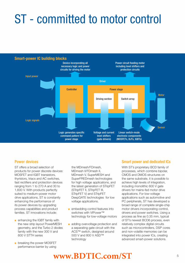
ST offers a broad selection of products for power discrete devices: MOSFET and IGBT transistors, thyristors, triacs and AC switches, fast rectifiers and protection devices ranging from 1 to 270 A and 30 to 1,600 V. With products perfectly suited to medium-power motor drive applications, ST is constantly enhancing the performance of its power devices by upgrading process capabilities and product families. ST innovations include:
n enhancing the IGBT family with the new strip layout PowerMESH geometry, and the Turbo 2 diodes family with the new 300 V and 600 V STTH series
n breaking the power MOSFET performance barrier by using
the MDmesh/FDmesh, MDmesh II/FDmesh II, MDmesh V, SuperMESH and SuperFREDmesh technologies for high voltage applications, and the latest generation of STripFET (STripFET II, STripFET III, STripFET V) and STripFET DeepGATE technologies for low voltage applications.
n embedding control features into switches with VIPower™ technology for low-voltage motors
n adding overvoltage protection and a separating gate circuit with the ACS™ switch, designed around 500 V and 800 V ASD™ technology
With ST’s proprietary BCD family of processes, which combine bipolar, CMOS and DMOS structures on the same substrate, it is possible to achieve high levels of integration, including monolithic 600 V gate drivers for mains-fed motor drive applications. For low-voltage applications such as automotive and PC peripherals, ST has developed a broad range of complete single-chip motor drivers incorporating control, drivers and power switches. Using a process as fine as 0.35 mm, typical of ST’s newest BCD6 process, even relatively complex digital circuits such as microcontrollers, DSP cores and non-volatile memories can be integrated into power ICs, creating advanced smart-power solutions.
Power devices Smart power and dedicated ICs
ST - committed to motor control
Smart-power IC building blocks
Logic generates specificcommand pattern for
power stage
Voltage and currentlevel shifters(gate drivers)
Linear switch-modeelectronic components(MOSFETs, BJTs, IGBTs)
Device incorporating allnecessary logic and power
circuits for driving the motor
Driver
Controller Power stage
Driving section Switch array
Power circuit feeding motorincluding level shifters and
protection circuits
Input power
Motor
Sensor
Logic signals
www.BDTIC.com/ST

6
Universal motors may be used with an AC or DC supply current. The stator and rotor windings of the motor are connected in series through the rotor commutator so that the mechanical force generated is always in the same direction (as it is proportional to the square of the current flowing). Operating at normal power-line frequencies, the maximum output of universal motors is limited and motors exceeding a few kilowatts are rare. The advantages of universal motors are specifically high starting torque, very compact design and high running speeds. The drawback is the maintenance and short life caused by the commutator.
The AC universal motor drive controls the rotation speed by means of phase-angle partialization. This method consists of changing the RMS voltage applied to the motor. In this case, the voltage is a function of the firing angle of the Triac. The high commutation capability of ACST-family device switches enables reliability of operation and use of a low gate-current supply for MCU interfacing.
Universal motor
100 to 240 Vac(or corresponding rectified voltage)
100 to 2,200 W 0 to 20,000 RPM High start-up and low-speed torque capability
Voltage Motor power Speed range Features
Typical application parameters
Main applications
AC universal motor drive
n Vacuum cleanersn Washing machinesn Power toolsn Food processors
Continuous speed control of a universal motor running on DC is very easily accomplished using a thyristor circuit. A thyristor supplies the motor during the positive mains half cycle. Both the thyristor and its control are connected in such a way that the motor back-EMF compensates the motor load variations to adjust the speed.
Main applications
DC universal motor drive
Umot (motor voltage)
Imot (motor current)
t
t
AC universal motor drive
Umot
Imot
t
t
DC universal motor drive
n Food processors n Power and garden tools
www.BDTIC.com/ST

7
Product highlightsMicrocontrollers
8-bit STM8 microcontrollers featuring a high-performance core (up to 20 MIPS @ 24 MHz), 3.3 V to 5.5 V power supply, embedded true EEPROM and RC oscillator and 4- to 128-Kbyte Flash in 20- to 80-pin packages.
Power transistorsThe IGBT is the best 600 V rated device for the PWM brushed DC motor drive. PowerMESH™ IGBTs combine low Vce(sat) with very short turn-off times, and significantly reduce both turn-on and turn-off switching losses. The latest low-voltage STripFET generations and STripFET DeepGATE technology for power MOSFETs for hand tools are also available.
Fast rectifiersAvailable at 300 V and 600 V, Turbo 2 diodes feature ultra-fast recovery while maintaining a low dropout voltage. They significantly cut losses in both the diode and transistor at turn-on.
ThyristorsThe thyristor (or SCR) delivers both rectification and motor voltage adjustment. A sensitive device (IGT < 200 μA) simplifies the gate drive and reduces overall control circuit dissipation.
AC switchesTriac and ACST switches are suited to this type of drive, offering high surge current and low conduction loss. ST’s Snubberless™, logic level Triacs require a low gate-triggering current (10 mA and 35 mA) and run safely without requiring a turn-off aid snubber. The new ACST switches are designed with intrinsic overvoltage robustness, and safely suppress the mains voltage surges described in IEC 61000-4-5.
Amplifiers and comparators
Operating at low voltage with rail-to-rail input and output capability, new op-amps bring innovation with very high merit factors and consumption below 1 mA, while offering high slew rate, 10 V/µs and large product gain bandwidth (up to 20 MHz). For high-voltage operation, standard CMOS or bipolar op-amps and comparators offer single-supply operation, with adequate speed.
STEVAL-IHM007V1 Universal motor control starter kit (phase-angle partialization)
STEVAL-IHM013V1 Low-end solution for a vacuum cleaner control board up to 2 kW
STEVAL-IHT00441 AC timer based on HT triacs and ST7Lite1b
Order code Description
Demonstration boards
The pulse width modulation (PWM) technique (also known as chopper drive) is used to adjust the voltage applied to the motor. With the variation of the PWM duty cycle, the effective voltage seen by the motor can be changed. The advantage of PWM modulation with respect to phase-angle partialization is higher efficiency, less acoustic noise and better EMC behavior, but it can have an impact on brush life duration.
Main applicationsn Washing machinesn Food processors
n Treadmillsn Industrial motion control
High-frequency PWM universal motor drive
Umot
Imot
t
t
High-frequency PWM universal motor drive
www.BDTIC.com/ST

8
Brushed DC motors are internally commutated electric motors designed to run from a DC power source. Generally, the rotational speed of a DC motor is proportional to the voltage applied to it, and the torque is proportional to the current. Speed can be controlled by a variable supply voltage or electronic controls. Controlling the speed of a brushed DC motor is simple - the higher the armature voltage, the faster the rotation. This relationship is linear up to the motor’s maximum speed. Here we address the permanent magnet DC motor where the stator is composed of two or more permanent-magnet pole pieces and the rotor is composed of windings that are connected to a mechanical commutator.
Brushed DC motor
A single-switch chopper can seamlessly control the speed using duty cycle modulation.
6 to 320 Vdc Up to 20,000 W 0 to 30,000 RPM
Voltage Motor power Speed range
Typical application parameters
Single-switch chopper drive
Main applicationsn Consumer audio/videon Shaversn Toysn Cordless toolsn Automotive body functions
n Tractionn Servomechanismsn Factory automationn Machine tools
Single-switch chopper drive
A full-bridge converter drive consists of four power switches that are used to adjust the motor voltage and polarity using the pulse width modulation (PWM) technique. The current can thus be controlled to flow in either direction through the motor windings, allowing the motor to run in both directions.
Full-bridge converter drive
Full-bridge converter drive
www.BDTIC.com/ST

9
Product highlightsMicrocontrollers
8-bit STM8 microcontrollers featuring a high-performance core (up to 20 MIPS @ 24 MHz), 3.3 V to 5.5 V power supply, embedded true EEPROM and RC oscillator and 4- to 128-Kbyte Flash in 20- to 80-pin packages.
Power transistorsThe latest low-voltage STripFET generations and STripFET DeepGATE power MOSFETs are ideal for higher power applications such as cordless tools.
Smart-power ICs
Monolithic motor drivers can be used conveniently in applications where the input voltage does not exceed a few dozen volts and the current feeding the motor windings is limited to a few amps. These devices may include just the power stage, the control section or the full control section, including the PWM current control, plus several protection functions such as thermal shut-down, overcurrent and cross-conduction. ST has developed several types of power IC, suited to different application requirements, working in linear or switch mode.
Gate drivers Monolithic full-bridge and half-bridge gate drivers are available and include protection, deadtime and supply circuits.
Amplifiers and comparators
Operating at low voltage with rail-to-rail input and output capability, new op-amps bring innovation with very high merit factors and consumption below 1 mA, while offering high slew rate, 10 V/µs and large product gain bandwidth (up to 20 MHz). For high-voltage operation, standard CMOS or bipolar op-amps and comparators offer single-supply operation, with adequate speed.
Order code Description
Demonstration boards
STEVAL-IHM012V1 Cordless-drill evaluation board based on power MOSFET and 8-pin MCU
STEVAL-IHM015V1 Low-voltage motor control demokit
EVAL6205/6/7N Integrated power stages with Powerspin
EVAL6205N PowerSpin with PWM current controller (L6205 + L6506)
EVAL6206N/PD PowerSpin with PWM current controller (L6206 + L6506)
EVAL6207N PowerSpin with PWM current controller (L6207)
EVAL6225PD PowerSpin with PWM current controller (L6225 + L6506)
EVAL6227PD/QR PowerSpin with PWM current controller (L6225)
EVAL6226QR PowerSpin (L6226)
www.BDTIC.com/ST
10
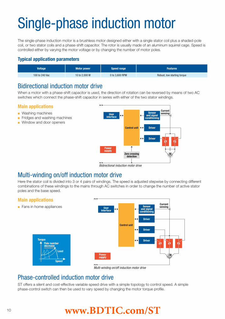
The single-phase induction motor is a brushless motor designed either with a single stator coil plus a shaded-pole coil, or two stator coils and a phase-shift capacitor. The rotor is usually made of an aluminum squirrel cage. Speed is controlled either by varying the motor voltage or by changing the number of motor poles.
When a motor with a phase-shift capacitor is used, the direction of rotation can be reversed by means of two AC switches which connect the phase-shift capacitor in series with either of the two stator windings.
Single-phase induction motor
100 to 240 Vac 10 to 2,000 W 0 to 3,600 RPM Robust, low starting torque
Voltage Motor power Speed range Features
Typical application parameters
Main applications
Bidirectional induction motor drive
n Washing machinesn Fridges and washing machinesn Window and door openers
Here the stator coil is divided into 3 or 4 pairs of windings. The speed is adjusted stepwise by connecting differentcombinations of these windings to the mains through AC switches in order to change the number of active stator poles and the base speed.
Main applications
Multi-winding on/off induction motor drive
n Fans in home appliances
Bidirectional induction motor drive
Phase-controlled induction motor drive
Torque
Load
Speed
Pole numberdecrease
Multi-winding on/off induction motor drive
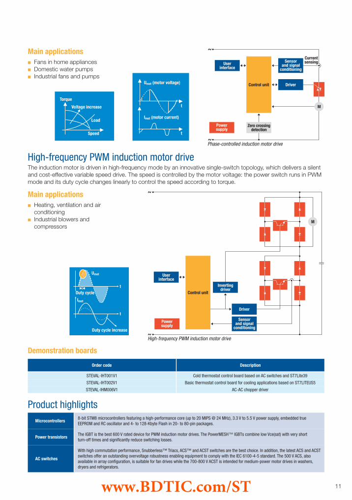
ST offers a silent and cost-effective variable speed drive with a simple topology to control speed. A simplephase-control switch can then be used to vary speed by changing the motor torque profile.
www.BDTIC.com/ST
11
Product highlightsMicrocontrollers
8-bit STM8 microcontrollers featuring a high-performance core (up to 20 MIPS @ 24 MHz), 3.3 V to 5.5 V power supply, embedded true EEPROM and RC oscillator and 4- to 128-Kbyte Flash in 20- to 80-pin packages.
Power transistorsThe IGBT is the best 600 V rated device for PWM induction motor drives. The PowerMESH™ IGBTs combine low Vce(sat) with very shortturn-off times and significantly reduce switching losses.
AC switches
With high commutation performance, Snubberless™ Triacs, ACS™ and ACST switches are the best choice. In addition, the latest ACS and ACST switches offer an outstanding overvoltage robustness enabling equipment to comply with the IEC 6100-4-5 standard. The 500 V ACS, also available in array configuration, is suitable for fan drives while the 700-800 V ACST is intended for medium-power motor drives in washers, dryers and refrigerators.
Main applicationsn Fans in home appliancesn Domestic water pumpsn Industrial fans and pumps
The induction motor is driven in high-frequency mode by an innovative single-switch topology, which delivers a silent and cost-effective variable speed drive. The speed is controlled by the motor voltage: the power switch runs in PWM mode and its duty cycle changes linearly to control the speed according to torque.
Main applications
High-frequency PWM induction motor drive
n Heating, ventilation and air conditioningn Industrial blowers and compressors
Torque
Voltage increase
Load
Speed
Phase-controlled induction motor drive
Umot (motor voltage)
Imot (motor current)
t
t
Umot
Duty cycle
Imot
Duty cycle increase
t
t
High-frequency PWM induction motor drive
Demonstration boards
Order code Description
STEVAL-IHT001V1 Cold thermostat control board based on AC switches and ST7Lite39
STEVAL-IHT002V1 Basic thermostat control board for cooling applications based on ST7LITEUS5
STEVAL-IHM006V1 AC-AC chopper driver
www.BDTIC.com/ST

12
The three-phase induction motor is a brushless motor. Its stator is copper wound and the rotor is typically analuminum squirrel cage. The motor is supplied with three alternating voltages which produce a rotating stator fieldwhile speed varies with the field frequency. The rotor follows this field with a lag called the slip.
Scalar control is typically achieved by controlling the voltage-to-frequency (V/f) ratio, thus the stator voltage amplitude (V) is adjusted proportionally to the stator current frequency (f).If rotor-speed feedback is available, slip regulation can be implemented to optimize drive dynamics and efficiency (MTPA - maximum torque per ampere - control).
Three-phase induction motor
100 to 240 Vac 50 to 2,200 W 0 to 20,000 RPM Robust, silent and reliable
Voltage Motor power Speed range Features
Typical application parameters
Main applications
Scalar V/f drive
n Washing machinesn Heating, ventilation and air conditioning
n Blowers, fans and pumpsn Industrial control
Order code Description
Demonstration boards
STEVAL-IHM001V1 BLDC and AC motor control board
STEVAL-IHM003V1 BLDC and AC motor control - 300 W power board
STEVAL-IHM004V1 BLDC and AC motor control - 1 kW power board
STEVAL-IHM005V1 BLDC and AC motor control - 3 kW power board
STEVAL-IHM008V1 Power board based on SEMITOP 2
STEVAL-IHM009V1 Power board based on SEMITOP 3
STEVAL-IHM010V1 IGBT power module kit - ST7MC control board
STEVAL-IHM011V1 IGBT power module kit - SEMITOP 2 power board
STEVAL-IHM017V1 100 W 3-phase inverter for BLDC sensorless motor control
STEVAL-IHM019V1 Complete inverter for low-power 3-phase AC motors
STEVAL-IHM021V1 BLDC and AC sensorless motor control (L6390) - 100 W power board
Centered pattern switching
Motorcurrent
ABC
Scalar V/f drive
www.BDTIC.com/ST

13
Vector driveVector control provides real-time processing of the stator phase current and rotor position. It provides four-quadrant operation and excellent dynamic behavior to give optimum efficiency and speed response time. In in the context of FOC (field-oriented control), if the rotor flux position is indirectly calculated using the transformed equations of the machine and the known motor parameters and stator current measurements, the controller is an indirect controller and is known as an IFOC drive.
Main applicationsn Roboticsn High-end industrial control
n Servo drives
Product highlights
Microcontrollers
8-bit STM8 microcontrollers featuring a high-performance core (up to 20 MIPS @ 24 MHz), 3.3 V to 5.5 V power supply, embedded true EEPROM and RC oscillator and 4- to 128-Kbyte Flash in 20- to 80-pin packages.32-bit STM32 microcontrollers based on the breakthrough ARM Cortex™-M3 core offering new degrees of freedom to MCU users: high-performance, real-time, low-power and low-voltage operation, while maintaining full integration and ease of development; six PWM advanced control timers with embedded deadtime generation; numerous PWM outputs allowing multiple motor drives; dual sample and hold ADC, 12-bit resolution and 1 μs conversion time; up to 512 Kbytes of Flash and 64 Kbytes of RAM.
Power transistors
Available at 600 V, PowerMESH IGBTs range from 3 to 50 A. To reduce component count on the board, they can be provided with a built-inTurbo 2 freewheeling diode. The low Vce(sat) combined with very short fall times significantly reduces both on and switching losses, while thefast-recovery diode further reduces the IGBT turn-on losses. For very low current applications, SuperMESH and SuperFREDmesh power MOSFETs are also available.
Fast rectifiersAvailable at 300 and 600 V, Turbo 2 diodes feature ultra-fast recovery while maintaining a low dropout voltage.They significantly cut losses in both the diode and the transistor at turn-on.
Gate driversHalf-bridge gate drivers are 600 V monolithic circuits which may include a bootstrap diode for the floating driver, deadtime circuitry, two UVLO circuits and an uncommitted comparator for protection functions. Signal and power grounds are separated to ensure high noiseimmunity.
Amplifiers and comparators
Operating at low voltage with rail-to-rail input and output capability, new op-amps bring innovation with very high merit factors and consumption below 1 mA, while offering high slew rate, 10 V/µs and large product gain bandwidth (up to 20 MHz). For high-voltage operation, standard CMOS or bipolar op-amps and comparators offer single-supply operation, with adequate speed.
STM3210B-MCKIT ST motor control starter kit
STEVAL-IHM017V1 100 W 3-phase inverter for BLDC sensorless motor control
STEVAL-IHM021V1 BLDC and AC sensorless motor control (L6390) - 100 W power board
Vector driveFOC block diagram
Order code Description
Demonstration boards
www.BDTIC.com/ST

14
Permanent-magnet synchronous motors (PMSMs) are synchronous brushless motors composed of two main components: a rotor made of permanent magnets and a wound stator. A motor is categorized as a BLDC or brushless DC motor when the stator windings are concentrated into narrow phase belts and the resulting back-EMF voltage induced in each motor phase by the rotor spinning can be modeled quite accurately as a trapezoidal waveform. Due to the back-EMF shape, BLDC motors are specifically optimized to develop nearly constant output torque when excited with a six-step switched current waveform.
The motor is supplied by three trapezoidal 6-step waveforms. During each step, two phases are active. In sensorless mode, the inactive phase is monitored to read the back-EMF.
Brushless DC PMSM
Up to 60 Vdc; 100 to 240 Vac 5 to 2,200 W 0 to 30,000 RPMHigh torque capability at start-up and low speed
Highly efficient and compact
Voltage Motor power Speed range Features
Typical application parameters
Main applications
Scalar 6-step drive
n Heating, ventilation and air conditioningn Refrigeratorsn Medical equipmentn Roboticsn Home appliances
n Fansn Pumpsn Hard disk drivesn CD/DVD drivesn Electric traction
Order code Description
Demonstration boards
STEVAL-IHM001V1 BLDC and AC motor control board
STEVAL-IHM003V1 BLDC and AC motor control - 300 W power board
STEVAL-IHM004V1 BLDC and AC motor control - 1 kW power board
STEVAL-IHM005V1 BLDC and AC motor control - 3 kW power board
STEVAL-IHM008V1 Power board based on SEMITOP 2
STEVAL-IHM009V1 Power board based on SEMITOP 3
STEVAL-IHM010V1 IGBT power module kit - ST7MC control board
STEVAL-IHM011V1 IGBT power module kit - SEMITOP 2 power board
STEVAL-IHM017V1 100 W 3-phase inverter for BLDC sensorless motor control
EVAL6235N Hall-effect sensor monolithic driver
EVAL6229PD Hall-effect sensor monolithic driver
Back-EMF
Current
t
Scalar 6-step drive
www.BDTIC.com/ST
15
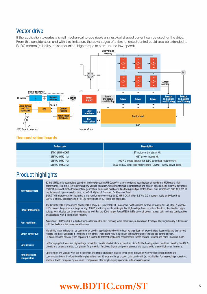
Vector drive
Product highlights
Microcontrollers
32-bit STM32 microcontrollers based on the breakthrough ARM Cortex™-M3 core offering new degrees of freedom to MCU users: high-performance, real-time, low-power and low-voltage operation, while maintaining full integration and ease of development; six PWM advanced control timers with embedded deadtime generation; numerous PWM outputs allowing multiple motor drives; dual sample and hold ADC, 12-bit resolution and 1 μs conversion time; up to 512 Kbytes of Flash and 64 Kbytes of RAM.8-bit STM8 microcontrollers featuring a high-performance core (up to 20 MIPS @ 24 MHz), 3.3 V to 5.5 V power supply, embedded true EEPROM and RC oscillator and 4- to 128-Kbyte Flash in 20- to 80-pin packages.
Power transistors
The latest STripFET generations and STripFET DeepGATE power MOSFETs are ideal PWM switches for low-voltage buses. As either N-channel or P-channel, they come in a large variety of SMD and through-hole packages. For high-voltage low-current applications, the standard high-voltage technologies can be usefully used as well. For the 600 V range, PowerMESH IGBTs cover all power ratings, both in single configuration or associated with a Turbo 2 fast rectifier.
Fast rectifiersAvailable at 300 V and 600 V, Turbo 2 diodes feature ultra-fast recovery while maintaining a low dropout voltage. They significantly cut losses in both the diode and the transistor at turn-on.
Smart power ICsMonolithic motor drivers can be conveniently used in applications where the input voltage does not exceed a few dozen volts and the current feeding the motor windings is limited to a few amps. These parts may include just the power stage or include the control section.ST has developed several types of power ICs, suited to different application requirements. Some operate in linear and some in switch mode.
Gate driversHalf-bridge gate drivers are high-voltage monolithic circuits which include a bootstrap diode for the floating driver, deadtime circuitry, two UVLO circuits and an uncommitted comparator for protection functions. Signal and power grounds are separated to ensure high noise immunity.
Amplifiers and comparators
Operating at low voltage with rail-to-rail input and output capability, new op-amps bring innovation with very high merit factors and consumption below 1 mA, while offering high slew rate, 10 V/µs and large product gain bandwidth (up to 20 MHz). For high-voltage operation, standard CMOS or bipolar op-amps and comparators offer single-supply operation, with adequate speed.
If the application tolerates a small mechanical torque ripple a sinusoidal shaped current can be used for the drive. From this consideration and with this limitation, the advantages of a field-oriented control could also be extended to BLDC motors (reliability, noise reduction, high torque at start-up and low-speed).
Vector drive
Demonstration boards
Order code Description
STM3210B-MCKIT ST motor control starter kit
STEVAL-IHM011V1 IGBT power module kit
STEVAL-IHM017V1 100 W 3-phase inverter for BLDC sensorless motor control
STEVAL-IHM021V1 BLDC and AC sensorless motor control (L6390) - 100 W power board
FOC block diagram
www.BDTIC.com/ST

16
The motor is categorized as PMSM or sinusoidal PMSM or PMAC when the stator windings are sinusoidally distributed and the magnets are shaped to induce a sinusoidal back-EMF voltage waveform in each motor phase by the rotor spinning. Due to the back-EMF shape, sinusoidal PMSMs are specifically optimized to develop nearly constant output torque when excited with a 3-phase sinusoidal current waveform.
To avoid applying too high a voltage for the current frequency, a V/f limitation curve is used to fix the maximum voltage value supplied for the stator frequency.
Brushless AC PMSM
Up to 380 Vac Up to 3 kW Up to 30,000 rpmHigh torque capability at start-up and low speed
Highly efficient and compact
Voltage Motor power Speed range Features
Typical application parameters
Main applications
Scalar drive
n Dishwashersn Electric traction
n Washing machinesn Robotics
Scalar drive
www.BDTIC.com/ST

17
Product highlights
Microcontrollers
32-bit STM32 microcontrollers based on the breakthrough ARM Cortex™-M3 core offering new degrees of freedom to MCU users: high-performance, real-time, low-power and low-voltage operation, while maintaining full integration and ease of development; six PWM advanced control timers with embedded deadtime generation; numerous PWM outputs allowing multiple motor drives; dual sample and hold ADC, 12-bit resolution and 1 μs conversion time; up to 512 Kbytes of Flash and 64 Kbytes of RAM.8-bit STM8 microcontrollers featuring a high-performance core (up to 20 MIPS @ 24 MHz), 3.3 V to 5.5 V power supply, embedded true EEPROM and RC oscillator and 4- to 128-Kbyte Flash in 20- to 80-pin packages.
Power transistors
The latest STripFET generations and STripFET DeepGATE power MOSFETs are ideal PWM switches for low-voltage buses. As either N-channel or P-channel, they come in a large variety of SMD and through-hole packages. For high-voltage low-current applications, the standard high-voltage technologies can be usefully used as well. For the 600 V range, PowerMESH IGBTs cover all power ratings, both in single configuration or associated with a Turbo 2 fast rectifier.
Fast rectifiersAvailable at 300 V and 600 V, Turbo 2 diodes feature ultra-fast recovery while maintaining a low dropout voltage. They significantly cut losses in both the diode and the transistor at turn-on.
Smart power ICsMonolithic motor drivers can be conveniently used in applications where the input voltage does not exceed a few dozen volts and the current feeding the motor windings is limited to a few amps. These parts may include just the power stage or include the control section.ST has developed several types of power ICs, suited to different application requirements. Some operate in linear and some in switch mode.
Gate driversHalf-bridge gate drivers are high-voltage monolithic circuits which include a bootstrap diode for the floating driver, deadtime circuitry, two UVLO circuits and an uncommitted comparator for protection functions. Signal and power grounds are separated to ensure high noise immunity.
Amplifiers and comparators
Operating at low voltage with rail-to-rail input and output capability, new op-amps bring innovation with very high merit factors and consumption below 1 mA, while offering high slew rate, 10 V/µs and large product gain bandwidth (up to 20 MHz). For high-voltage operation, standard CMOS or bipolar op-amps and comparators offer single-supply operation, with adequate speed.
Demonstration boards
Order code Description
STM3210B-MCKIT ST motor control starter kit
STEVAL-IHM011V1 IGBT power module kit
STEVAL-IHM017V1 100 W 3-phase inverter for BLDC sensorless motor control
STEVAL-IHM021V1 BLDC and AC sensorless motor control (L6390) - 100 W power board
Vector driveVector control processes the stator phase current and rotor position in real time. It provides four-quadrant operation and excellent dynamic behavior, to give optimum efficiency, and torque and speed response times. Sensorless algorithms for rotor position detection are available.
Vector drive
www.BDTIC.com/ST
18
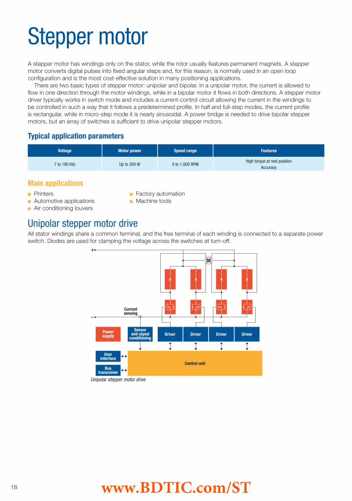
A stepper motor has windings only on the stator, while the rotor usually features permanent magnets. A stepper motor converts digital pulses into fixed angular steps and, for this reason, is normally used in an open loop configuration and is the most cost-effective solution in many positioning applications. There are two basic types of stepper motor: unipolar and bipolar. In a unipolar motor, the current is allowed to flow in one direction through the motor windings, while in a bipolar motor it flows in both directions. A stepper motor driver typically works in switch mode and includes a current-control circuit allowing the current in the windings to be controlled in such a way that it follows a predetermined profile. In half and full-step modes, the current profile is rectangular, while in micro-step mode it is nearly sinusoidal. A power bridge is needed to drive bipolar stepper motors, but an array of switches is sufficient to drive unipolar stepper motors.
All stator windings share a common terminal, and the free terminal of each winding is connected to a separate power switch. Diodes are used for clamping the voltage across the switches at turn-off.
Stepper motor
7 to 180 Vdc Up to 300 W 0 to 1,000 RPMHigh torque at rest position
Accuracy
Voltage Motor power Speed range Features
Typical application parameters
Main applications
Unipolar stepper motor drive
n Printersn Automotive applicationsn Air conditioning louvers
n Factory automationn Machine tools
Unipolar stepper motor drive
www.BDTIC.com/ST

19
A full-bridge converter is required to drive each of the two windings of a two-phase motor.
Two-phase bipolarstepper motor drive
Order code Description
Demonstration boards
Product highlights
Microcontrollers
8-bit STM8 microcontrollers featuring a high-performance core (up to 20 MIPS @ 24 MHz), 3.3 V to 5.5 V power supply, embedded true EEPROM and RC oscillator and 4- to 128-Kbyte Flash in 20- to 80-pin packages.32-bit STM32 microcontrollers based on the breakthrough ARM Cortex™-M3 core offering new degrees of freedom to MCU users: high-performance, real-time, low-power and low-voltage operation, while maintaining full integration and ease of development; six PWM advanced control timers with embedded deadtime generation; numerous PWM outputs allowing multiple motor drives; dual sample and hold ADC, 12-bit resolution and 1 μs conversion time; up to 512 Kbytes of Flash and 64 Kbytes of RAM.
Power transistorsThe latest STripFET generations and STripFET DeepGATE power MOSFETs are suitable for low-voltage stepper motors in automotive and industrial applications. They are ideal for higher power applications such as printers.
Smart-power ICs
Monolithic motor drivers can be conveniently used in applications where the input voltage does not exceed a few dozen volts and the current feeding the motor windings is limited to a few amps. These parts may include just the power stage or the control section as well.ST has developed several types of power IC which suit different application requirements; some work in half/full step and some in micro stepping mode.
Gate driversHalf-bridge gate drivers are high-voltage monolithic circuits which include a bootstrap diode for the floating driver, deadtime circuitry, two UVLO circuits and an uncommitted comparator for protection functions. Signal and power grounds are separated to ensure high noise immunity.
EVAL6205/6/7N Integrated power stages with PowerSpin
EVAL6205N PowerSpin with PWM current controller (L6205+L6506)
EVAL6206N/PD PowerSpin with PWM current controller (L6206+L6506)
EVAL6207N PowerSpin with PWM current controller (L6207)
EVAL6225PD PowerSpin with PWM current controller (L6225+L6506)
EVAL6227PD/QR PowerSpin with PWM current controller (L6225)
EVAL6226QR PowerSpin (L6226)
EVAL6208N/PD PowerSpin with stepper translator plus PWM current controller (L6208)
EVAL6228QR PowerSpin with stepper translator plus PWM current controller (L6208)
A three-phase inverter is needed to drive a three-phase motor. Multi-phase stepper motors with many phases tend to have much lower levels of vibration, although the cost of manufacture is higher.
Multi-phase bipolar stepper motor drive
Two-phase bipolar stepper motor drive
Multi-phase bipolar stepper motor drive
www.BDTIC.com/ST
20
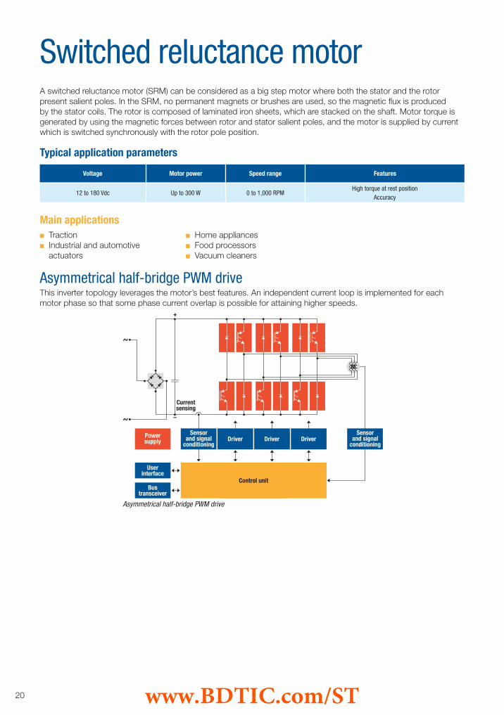
A switched reluctance motor (SRM) can be considered as a big step motor where both the stator and the rotor present salient poles. In the SRM, no permanent magnets or brushes are used, so the magnetic flux is produced by the stator coils. The rotor is composed of laminated iron sheets, which are stacked on the shaft. Motor torque is generated by using the magnetic forces between rotor and stator salient poles, and the motor is supplied by current which is switched synchronously with the rotor pole position.
This inverter topology leverages the motor’s best features. An independent current loop is implemented for each motor phase so that some phase current overlap is possible for attaining higher speeds.
Switched reluctance motor
12 to 180 Vdc Up to 300 W 0 to 1,000 RPMHigh torque at rest position
Accuracy
Voltage Motor power Speed range Features
Typical application parameters
Main applications
Asymmetrical half-bridge PWM drive
n Tractionn Industrial and automotive actuators
n Home appliancesn Food processorsn Vacuum cleaners
Asymmetrical half-bridge PWM drive
www.BDTIC.com/ST
21
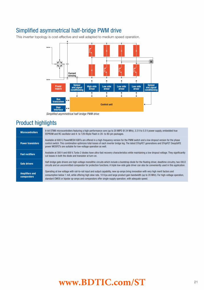
This inverter topology is cost-effective and well adapted to medium speed operation.
Simplified asymmetrical half-bridge PWM drive
Product highlightsMicrocontrollers
8-bit STM8 microcontrollers featuring a high-performance core (up to 20 MIPS @ 24 MHz), 3.3 V to 5.5 V power supply, embedded true EEPROM and RC oscillator and 4- to 128-Kbyte Flash in 20- to 80-pin packages.
Power transistorsAvailable at 600 V, PowerMESH IGBTs are offered in a high-frequency version for the PWM switch and a low dropout version for the phasecontrol switch. This combination optimizes total losses of each inverter bridge leg. The latest STripFET generations and STripFET DeepGATE power MOSFETs are suitable for low-voltage operation as well.
Fast rectifiersAvailable at 300 V and 600 V, Turbo 2 diodes have ultra-fast recovery characteristics while maintaining a low dropout voltage. They significantly cut losses in both the diode and transistor at turn-on.
Gate driversHalf-bridge gate drivers are high-voltage monolithic circuits which include a bootstrap diode for the floating driver, deadtime circuitry, two UVLO circuits and an uncommitted comparator for protection functions. A triple low-side gate driver can also be conveniently used in this application.
Amplifiers and comparators
Operating at low voltage with rail-to-rail input and output capability, new op-amps bring innovation with very high merit factors and consumption below 1 mA, while offering high slew rate, 10 V/µs and large product gain bandwidth (up to 20 MHz). For high-voltage operation, standard CMOS or bipolar op-amps and comparators offer single-supply operation, with adequate speed.
Simplified asymmetrical half-bridge PWM drive
www.BDTIC.com/ST
22
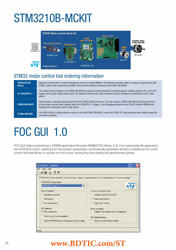
STM3210B-MCKIT
STM32 motor control tool ordering informationSTM3210B MC library
Optimized, documented C firmware libraries for control of 3-phase PMSM or AC induction brushless motors. In torque or speed control with STM32, sensor mode, sensorless for PMSM. These are the standalone libraries of the STM3210B-MCKIT.
AI-JTAG/OPTO-1The isolation board included in the STM3210B-MCKITcan also be ordered separately. It provides galvanic isolation between the J-Link from Segger and any high-voltage target board. The isolation board has two JTAG connectors (in/out). Available from distributors and ST sales offices.
STM3210B-MCKITDemonstration, evaluation and development kit for STM32 includes firmware, LCD user interface, STM3210B-EVAL board (control board), 7 A three-phase inverter board, isolation board (AI-JTAG/OPTO-1), Segger J-Link debugger/programmer and 24 VDC Shinano PMSM motor. Available from distributors and ST sales offices.
ST7MC-MOT/IND240 V/800 W Selni 3-phase induction motor for use with STM3210B-MCKIT, or with the ST7MC-KIT using induction motor default values (for evaluation purposes).
FOC GUI helps customizing a PMSM application firmware (PMSM FOC library 2.0). It is a parameter file generation tool (FOCGUI) which, starting from the system parameters, automatically generates all that is needed by the motor control firmware library to quickly run the motor, saving time and easing the development phase.
FOC GUI 1.0
www.BDTIC.com/ST

23
Class B Compliancy - how do we help?Two key features help compliance with the EN/IEC60335-1 norm: the dual watchdog architecture and the internal clock circuitry. In order to make certification even simpler with the STM32, a set of self-test routines has been developed to fulfill most of table H11.12.7 requirements. These routines have been certified by the VDE, a worldwide recognized test institute, and do not need to be re-evaluated if left unchanged.
Vector control librariesSTM32 library
Single-shunt current sensing
Internal permanent magnet motors (IPM)
Dual motor control and triple ADC system
Field weakening and feed-forward control
Optimized and documented C firmware libraries forcontrol of both PMSM (sensor and sensorless mode)and AC induction (sensor mode) brushless motors areavailable for free upon request.These libraries support IAR (EWARM), KEIL and Greenhills toolchain.These modular libraries support both types of motorin standalone mode using the hardware of theSTM3210B-MCKIT. The source files are provided free ofcharge upon request. These libraries offer:n Different current sensing methodologies n Isolated current sensing n Three shunt resistors n Single shunt topology with dual sample and hold utilization and advanced methodology for better bus voltage exploitationn Different rotor-position feedback n Tachometer (AC motor) n Hall sensors (60° and 120° placement) n Sensorless (PMSM motor only)Total execution time of the field-oriented control insensorless mode for PMSM motor is less than 21 μs Total CPU load at 10 kHz sampling time is below 25 % - code size is less than 14 Kbytes.
The STM32 motor control library version 2.0 supportssingle-shunt current sensing, for applications requiringlowest system costs. The proposed solution maximizesthe DC bus voltage use, while minimizing current distorsion and acoustical noise, and has been patentedby ST. The STM32-MCKIT can be easily reconfigured inone-shunt mode, for evaluation purposes.
Thanks to their higher power density and very highspeed capabilities, brushless IPM motors are used in anincreasing number of designs (vs. their surface mountedmagnets counterpart). The STM32 MC library supportsthis kind of motors with specific algorithms, such asMTPA (Maximum Torque Per Ampere) control strategy.
The High-density STM32 devices embed three ADCsand two motor control capable timers. This allows todrive simultaneously two brushless motors, or to have atriple Sample & hold current acquisition for very highendcontrol systems. These features are supported byadditional interrupt vectors and a second DMA controller.
The stator voltage closed loop Field Weakening controlimplemented is able to expand the operating limits ofboth surface mounted and internal PMSM, as manyapplications require. This algorithm strongly reducessensitivity to motor parameter and environmentalvariations.On top of this, feed forward control allows improvedbus voltage ripple compensation and better currentsregulation during high speed flux weakening operations.
www.BDTIC.com/ST

© STMicroelectronics - May 2009 - Printed in Italy - All rights reservedThe STMicroelectronics corporate logo is a registered trademark of the STMicroelectronics group of companies.
All other names are the property of their respective owners.
For more information on ST products and solutions, visit www.st.com
Order code: BRMOTOR0509 www.BDTIC.com/ST