BPU - Wacker Neusonproducts.wackerneuson.com/manuals/Operators/0210447en_001.pdf · Operator's...
36
www.wackergroup.com Operator's manual Vibrating plate BPU ... 0210447en 001 07.2006
Transcript of BPU - Wacker Neusonproducts.wackerneuson.com/manuals/Operators/0210447en_001.pdf · Operator's...

www.wackergroup.com
Operator's manual
Vibrating plate
BPU ...
0210447en 00107.2006

Contents
3
1. Foreword 5
2. Safety information 72.1 General instructions ..............................................................................72.2 Operation ...............................................................................................72.3 Safety checks ........................................................................................92.4 Maintenance ........................................................................................102.5 Transport .............................................................................................112.6 Maintenance checks ............................................................................11
3. Technical data 124. Description 14
4.1 Field of application ..............................................................................144.2 Max. permissible tilt .............................................................................144.3 Functional description .........................................................................15
5. Transport to the worksite 176. Recommendations for compacting 187. Operation 19
7.1 Start preparation ..................................................................................197.2 Starting the engine ..............................................................................197.3 Operating in the forward and reverse direction ...................................207.4 Turn off the engine ..............................................................................20
8. Maintenance 218.1 Maintenance schedule ........................................................................218.2 Checking engine oil level .....................................................................218.3 Changing the engine oil .......................................................................238.4 Cleaning the air filter / replacing the air filter inserts ...........................248.5 Checking / cleaning / replacing the spark plug ....................................258.6 Checking exciter V-belt .......................................................................268.7 Changing exciter V-belt .......................................................................268.8 Checking / filling hydraulic oil level ......................................................268.9 Checking exciter oil level .....................................................................278.10 Changing exciter oil .............................................................................27
9. Malfunction 289.1 Forward travel speed too low ..............................................................289.2 Reverse travel speed too low ..............................................................289.3 No forward movement .........................................................................289.4 Loss of hydraulic oil .............................................................................28

Contents
4
9.5 Engine will not start .............................................................................29
EC Declaration of Conformity 31
DIN EN ISO 9001 Certificate 33
Foreword
5
1. Foreword
For your own safety and protection from bodily injuries, carefully read,understand and follow the safety information in this manual.
Please operate and maintain your Wacker machine in accordance withthe instructions in this operator's manual. Your Wacker machine willreward you with troublefree operation and a high degree of availability.
Defective components must be replaced immediately.
All rights, especially the right for copying and distribution, are reserved
Copyright 2006 by Wacker Construction Equipment AG
No part of this publication may be reproduced in any form or by anymeans, electronic or mechanical, including photocopying, withoutexpress permission in writing from Wacker Construction Equipment AG.
Any type of reproduction, distribution or saving on data carriers of anytype or method not authorized by Wacker represents an infringement ofvalid copyrights and will be prosecuted. We expressly reserve the rightto make technical modifications - even without special notice - which aimat further improving our machines or their safety standards.
T00940en.fm 6
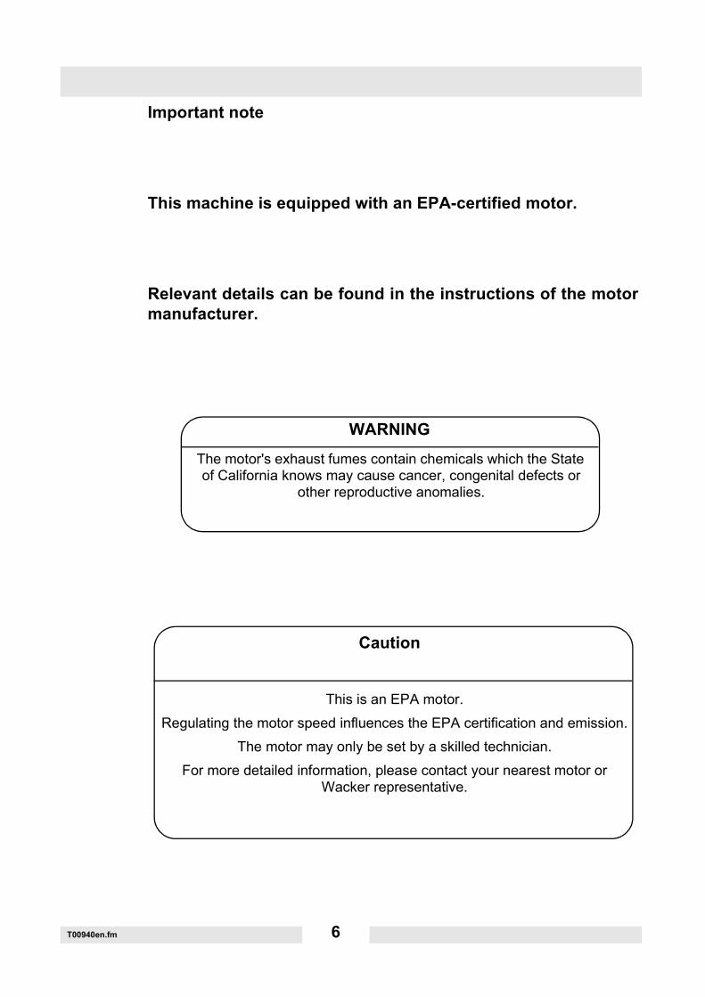
Important note
This machine is equipped with an EPA-certified motor.
Relevant details can be found in the instructions of the motormanufacturer.
The motor's exhaust fumes contain chemicals which the State of California knows may cause cancer, congenital defects or
other reproductive anomalies.
WARNING
Caution
This is an EPA motor.Regulating the motor speed influences the EPA certification and emission.
The motor may only be set by a skilled technician.For more detailed information, please contact your nearest motor or
Wacker representative.
Safety information
SV00069en.fm 7
2. Safety informationFor vibrating plates with combustion engine drive
2.1 General instructions
2.1.1 Vibrating plates may only be operated by persons who∗ are at least 18 years of age,∗ are physically and mentally fit for this job,∗ have been instructed in operating vibrating plates and have proved
their ability for the job to the employer,∗ may be expected to carry out the job they are charged with carefully.
The persons must be assigned the job of operating vibrating plates bythe employer.
2.1.2 Vibrating plates are to be applied only for compacting work. Both the
manufacturer's operator's manual and this safety information must beobserved.
2.1.3 The persons charged with the operation of vibrating plates must bemade familiar with the necessary safety measures relating to themachine. In case of extraordinary uses, the employer shall give thenecessary additional instructions.
2.1.4 It is possible that these vibrating plates exceed the admissible sound
level of 89 dB (A). If the sound level reaches 89 dB (A) or more, theemployees must wear ear protection.
2.2 Operation
2.2.1 The engine is started using a recoil starter. The decompressionautomatic allows an easy and kickback-free start-up procedure.
2.2.2 The function of operation levers or elements must not be influenced orrendered ineffective.
Safety information
SV00069en.fm 8
2.2.3 The operator must not leave the operator's area during the operationof the machine.
2.2.4 Before going on breaks, the operator must switch off the motor of the
machine. The machine must be set down so it cannot tip over.
2.2.5 The tank may only be filled when the motor is switched off and the fuelmust not make contact with hot parts or fall on the ground.
2.2.6 Open flames and smoking are strictly prohibited in the immediate
vicinity of this machine.
2.2.7 The tank lid must be tightly secured. When the motor is switched off,the fuel tap - if there is one - must be closed. When transported overlong distances, the tank of gasoline or mixed gasoline driven enginesmust be completely emptied.Leaking fuel tanks can lead to explosions and therefore must bereplaced immediately.
2.2.8 Do not operate this machine in areas where explosions may occur.
2.2.9 While operating vibrating plates with a combustion motor in closed
rooms, tunnels, drifts or deep trenches make sure that there is asufficient intake of fresh air.
2.2.10 While operating vibrating plates, keep hands, feet and clothing away
from moving parts. Protective shoes must be worn.
2.2.11 While working on cracked, cavity, acclivity or escarpment edges andon trench edges and steps, operate the vibrating plates so that theycannot tip over or fall down.
2.2.12 A sufficient load-bearing capacity of the surface or foundation to be
compacted must be ensured.
Safety information
SV00069en.fm 9
2.2.13 Wear suitable protective clothing during work and maintenance work.
2.2.14 When operating in the reverse direction, the operator must operate thevibrating plate from the side in order to protect themselves from beingcrushed between the end of the guide handle / machine and anobstacle. Great care is necessary when working on uneven terrain andcompacting large materials. A safe distance must be kept here.
2.2.15 Vibrating plates are to be guided in such a way that hand injuriescaused by solid objects are avoided.
2.2.16 Vibrating plates must be so installed and operated that their verticalstability is ensured.
2.2.17 Machines with integrated driving mechanisms must not be set down orstored on the chassis. The driving mechanism is only intended for thetransport of this machine.
2.3 Safety checks
2.3.1 Vibrating plates may only be operated with all safety devices installed.
2.3.2 Before starting operation, the operator has to check that all control and
safety devices are functioning properly.
2.3.3 If defects on the safety devices or other defects impairing the
operational safety of machine are observed, the supervisor must beinformed immediately.
2.3.4 If there are defects jeopardizing operational safety, the machine has to
be switched off immediately.
2.3.5 All auxiliary materials, fuel, lubricants and coolants are to be stored inmarked containers according to the manufacturer's regulations.
Safety information
SV00069en.fm 10
2.4 Maintenance
2.4.1 Only use original spare parts. Alterations to this machine, incl.adjustments of the maximum engine speed set by the manufacturermay only be carried out with the express permission of WACKER. Incase of non-observance, all liability shall be refused.
2.4.2 Maintenance work may only be carried out when the drives arestationary. If a spark plug connector is present, this should beremoved. This procedure may only be waived if the work cannot becarried out when the motor is switched off.
2.4.3 While using vibrating plates with an electronic start, the battery mustbe disconnected in each case before working on the electrical parts ofthe machine.
2.4.4 Hydraulic lines must be depressurized before working on them. Greatcare is required when disassembling hydraulic lines, as the oil canreach temperatures of up to 80 °C. Protect the eyes from splashes.
2.4.5 As soon as maintenance and repair jobs have been completed, allsafety devices must be properly reinstalled.
2.4.6 In order to prevent malfunctions, the machine should be cleaned usinga water hose after each use. High pressure cleaners or chemicalagents must not be used.
Safety information
SV00069en.fm 11
2.5 Transport
2.5.1 For the loading and transportation of compacting machines withhoisting gear, suitable sling chains must be secured at the relevantfixing point.
2.5.2 Loading ramps must be able to bear the load and be in a stableposition. Make sure that no one can be endangered if the machineslips away or tips over, or if parts suddenly move upward or downward.
2.5.3 When vibrating plates are being transported in vehicles, precautionshave to be taken to ensure that they do not slip or fall over.
2.6 Maintenance checks
2.6.1 According to the conditions and frequency of use, vibrating plates mustbe checked for safe operation at least once a year by skilledtechnicians, such as those employed by WACKER service stations,and repaired if necessary.
Please observe the appropriate rules and regulations valid in yourcountry.
Technical data
TD00732en.fm 12
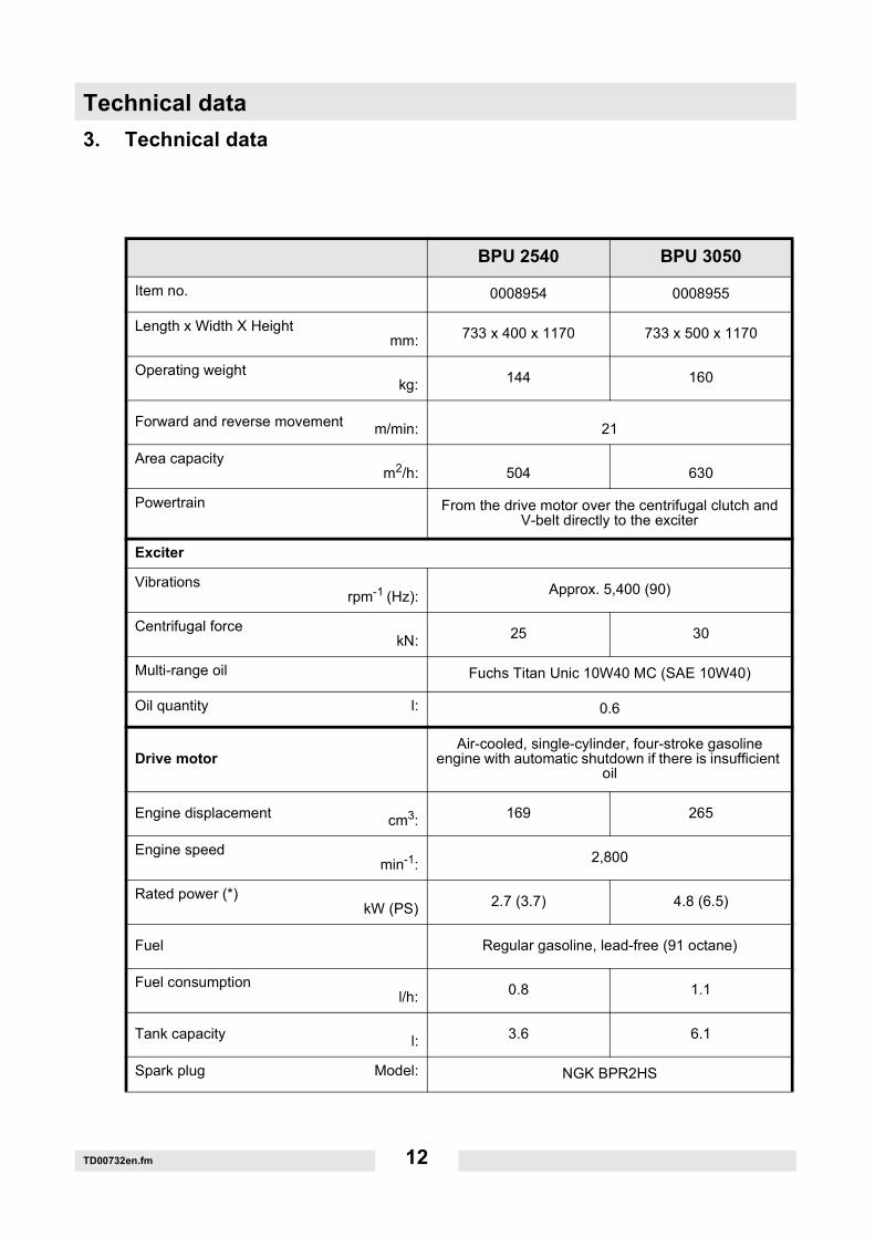
3. Technical data
BPU 2540 BPU 3050
Item no. 0008954 0008955
Length x Width X Heightmm: 733 x 400 x 1170 733 x 500 x 1170
Operating weightkg: 144 160
Forward and reverse movement m/min: 21
Area capacitym2/h: 504 630
Powertrain From the drive motor over the centrifugal clutch and V-belt directly to the exciter
Exciter
Vibrationsrpm-1 (Hz): Approx. 5,400 (90)
Centrifugal forcekN: 25 30
Multi-range oil Fuchs Titan Unic 10W40 MC (SAE 10W40)
Oil quantity l: 0.6
Drive motorAir-cooled, single-cylinder, four-stroke gasoline
engine with automatic shutdown if there is insufficient oil
Engine displacement cm3: 169 265
Engine speedmin-1: 2,800
Rated power (*)kW (PS) 2.7 (3.7) 4.8 (6.5)
Fuel Regular gasoline, lead-free (91 octane)
Fuel consumptionl/h: 0.8 1.1
Tank capacity l: 3.6 6.1
Spark plug Model: NGK BPR2HS
Technical data
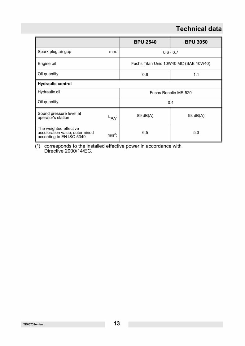
TD00732en.fm 13
(*) corresponds to the installed effective power in accordance withDirective 2000/14/EC.
Spark plug air gap mm: 0.6 - 0.7
Engine oil Fuchs Titan Unic 10W40 MC (SAE 10W40)
Oil quantity 0.6 1.1
Hydraulic control
Hydraulic oil Fuchs Renolin MR 520
Oil quantity 0.4
Sound pressure level at operator's station LPA: 89 dB(A) 93 dB(A)
The weighted effective acceleration value, determined according to EN ISO 5349 m/s2: 6.5 5.3
BPU 2540 BPU 3050
Description
T01090en.fm 14
4. Description
4.1 Field of application
4.1.1 BPU 2540Through the low width and continuous switchability especially suitablefor all surface compacting work in limited space conditions (e.g. incable trenches) or the compacting of edge trims when repairingblacktops, as well as all compacting work where the use of a largemachine is not possible.
4.1.2 BPU 3050The range of application reaches from trench and surface compacting,including semi-cohesive ground, to pressing interlocking pavingstones into place.
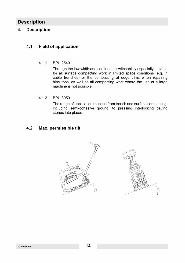
4.2 Max. permissible tilt
Description
T01090en.fm 15
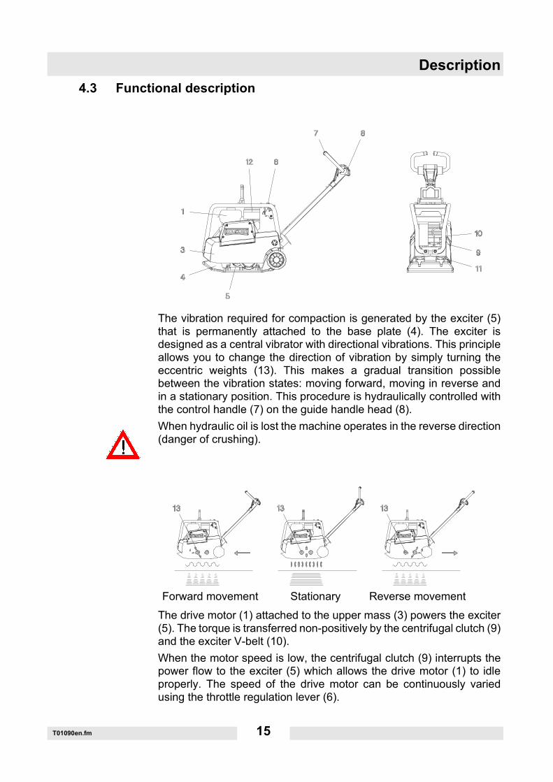
4.3 Functional description
The vibration required for compaction is generated by the exciter (5)that is permanently attached to the base plate (4). The exciter isdesigned as a central vibrator with directional vibrations. This principleallows you to change the direction of vibration by simply turning theeccentric weights (13). This makes a gradual transition possiblebetween the vibration states: moving forward, moving in reverse andin a stationary position. This procedure is hydraulically controlled withthe control handle (7) on the guide handle head (8).When hydraulic oil is lost the machine operates in the reverse direction(danger of crushing).
The drive motor (1) attached to the upper mass (3) powers the exciter(5). The torque is transferred non-positively by the centrifugal clutch (9)and the exciter V-belt (10).When the motor speed is low, the centrifugal clutch (9) interrupts thepower flow to the exciter (5) which allows the drive motor (1) to idleproperly. The speed of the drive motor can be continuously variedusing the throttle regulation lever (6).
Forward movement Stationary Reverse movement

Description
T01090en.fm 16
The upper mass (3) and the base plate (4) are connected to each othervia 4 vibration-damping rubber metal shockmounts (11). This dampingprevents very high frequencies from being transferred to the uppermass (3). This maintains proper functioning of the drive motor (1)despite a high compaction capacity.
Transport to the worksite
T01091en.fm 17
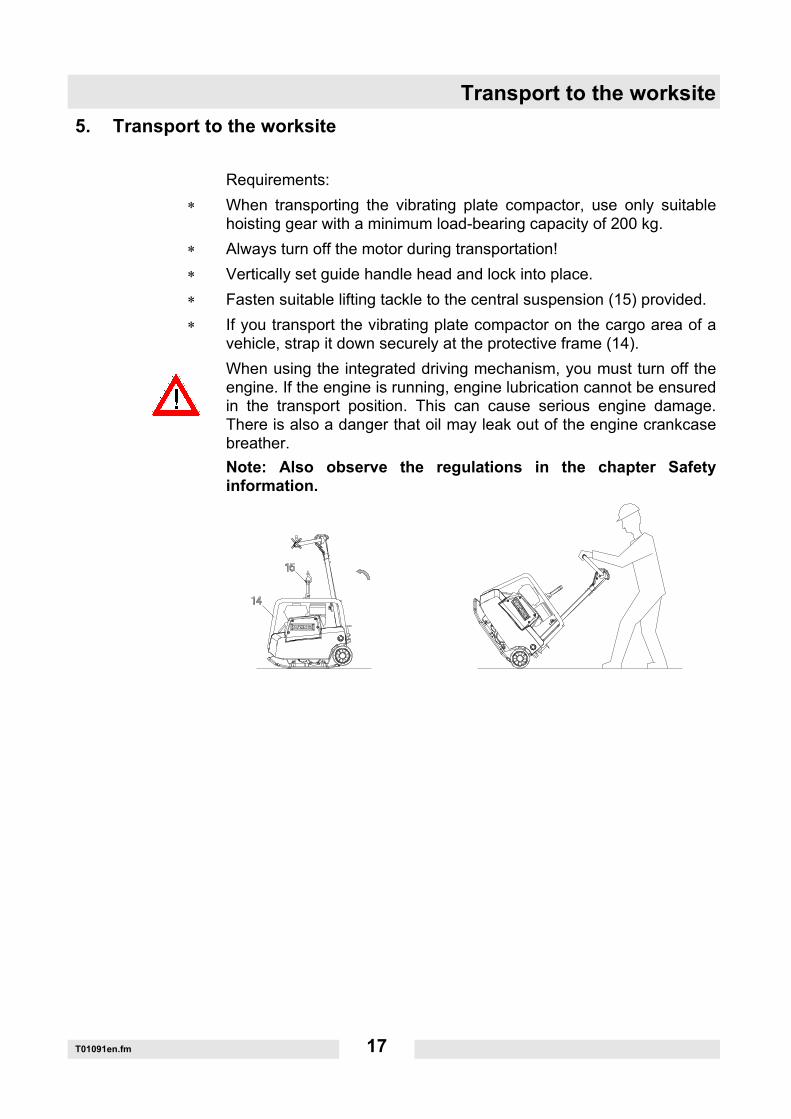
5. Transport to the worksite
Requirements:∗ When transporting the vibrating plate compactor, use only suitable
hoisting gear with a minimum load-bearing capacity of 200 kg.∗ Always turn off the motor during transportation!∗ Vertically set guide handle head and lock into place.∗ Fasten suitable lifting tackle to the central suspension (15) provided.∗ If you transport the vibrating plate compactor on the cargo area of a
vehicle, strap it down securely at the protective frame (14).When using the integrated driving mechanism, you must turn off theengine. If the engine is running, engine lubrication cannot be ensuredin the transport position. This can cause serious engine damage.There is also a danger that oil may leak out of the engine crankcasebreather.Note: Also observe the regulations in the chapter Safetyinformation.
Recommendations for compacting
T01091en.fm 18
6. Recommendations for compacting6.0.1 Condition of the ground
The maximum layer thickness depends on several factors such as thecondition of the ground/soil, the moisture, grading etc.This is why it is not always possible to make preciserecommendations.Recommendation: In certain cases, determine the maximum layerthickness by conducting compacting tests and taking ground samples.
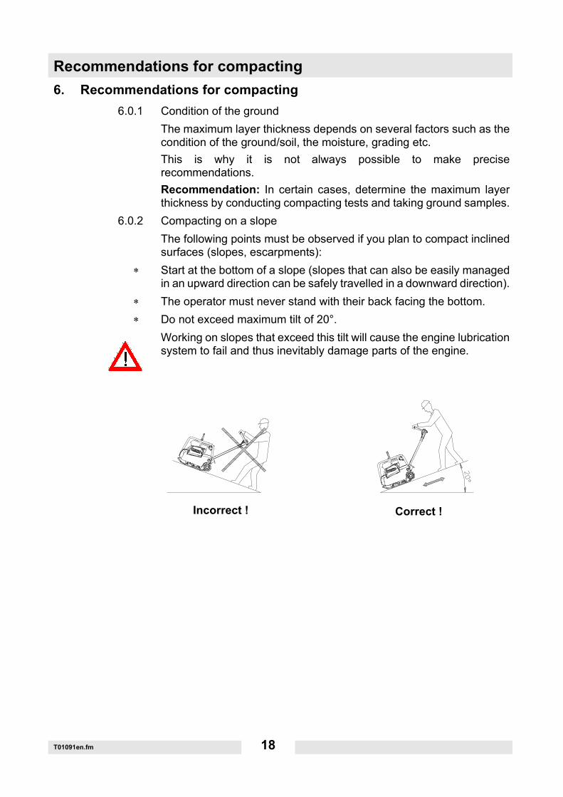
6.0.2 Compacting on a slopeThe following points must be observed if you plan to compact inclinedsurfaces (slopes, escarpments):
∗ Start at the bottom of a slope (slopes that can also be easily managedin an upward direction can be safely travelled in a downward direction).
∗ The operator must never stand with their back facing the bottom.∗ Do not exceed maximum tilt of 20°.
Working on slopes that exceed this tilt will cause the engine lubricationsystem to fail and thus inevitably damage parts of the engine.
Incorrect ! Correct !
Operation
T01092en.fm 19
7. Operation
7.1 Start preparation
Before you start the engine, check the following:Fuel level – the tank should be at least half full.Motor oil level.Air filter.Fuel lines for leaks.External screw connections for tightness.
7.2 Starting the engine
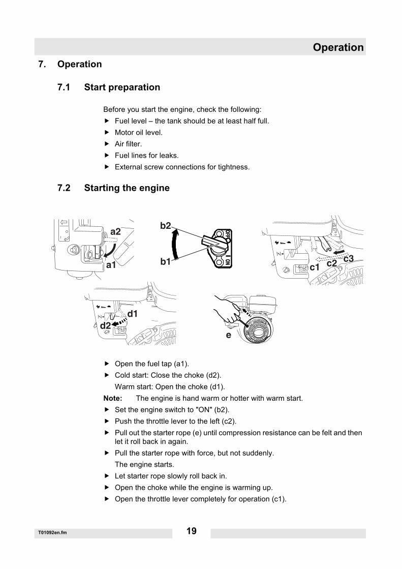
Open the fuel tap (a1).Cold start: Close the choke (d2).Warm start: Open the choke (d1).
Note: The engine is hand warm or hotter with warm start.Set the engine switch to "ON" (b2).Push the throttle lever to the left (c2).Pull out the starter rope (e) until compression resistance can be felt and then let it roll back in again.Pull the starter rope with force, but not suddenly.The engine starts.Let starter rope slowly roll back in.Open the choke while the engine is warming up.Open the throttle lever completely for operation (c1).
a1
a2b2
b1 c1 c2 c3
d2
wc_gr000655e
d1

Operation
T01092en.fm 20
7.3 Operating in the forward and reverse direction
Press the control handle in the direction of travel.Note: The forward and reverse speed can be continuously varied.
7.4 Turn off the engine
Push the throttle lever to the right to idle operation (c3).Set the engine switch to "OFF" (b1).Close the fuel tap (a2).
Maintenance
T01093en.fm 21
8. Maintenance
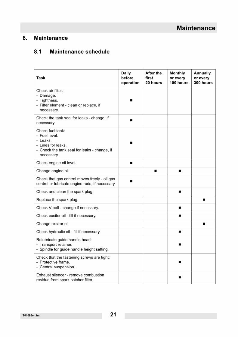
8.1 Maintenance schedule
TaskDaily before operation
After the first 20 hours
Monthly or every 100 hours
Annually or every 300 hours
Check air filter:- Damage.- Tightness.- Filter element - clean or replace, if
necessary.
Check the tank seal for leaks - change, if necessary.
Check fuel tank:- Fuel level.- Leaks.- Lines for leaks.- Check the tank seal for leaks - change, if
necessary.
Check engine oil level.
Change engine oil.
Check that gas control moves freely - oil gas control or lubricate engine rods, if necessary.
Check and clean the spark plug.
Replace the spark plug.
Check V-belt - change if necessary.
Check exciter oil - fill if necessary.
Change exciter oil.
Check hydraulic oil - fill if necessary.
Relubricate guide handle head:- Transport retainer.- Spindle for guide handle height setting.
Check that the fastening screws are tight:- Protective frame.- Central suspension.
Exhaust silencer - remove combustion residue from spark catcher filter.
Maintenance
T01093en.fm 22
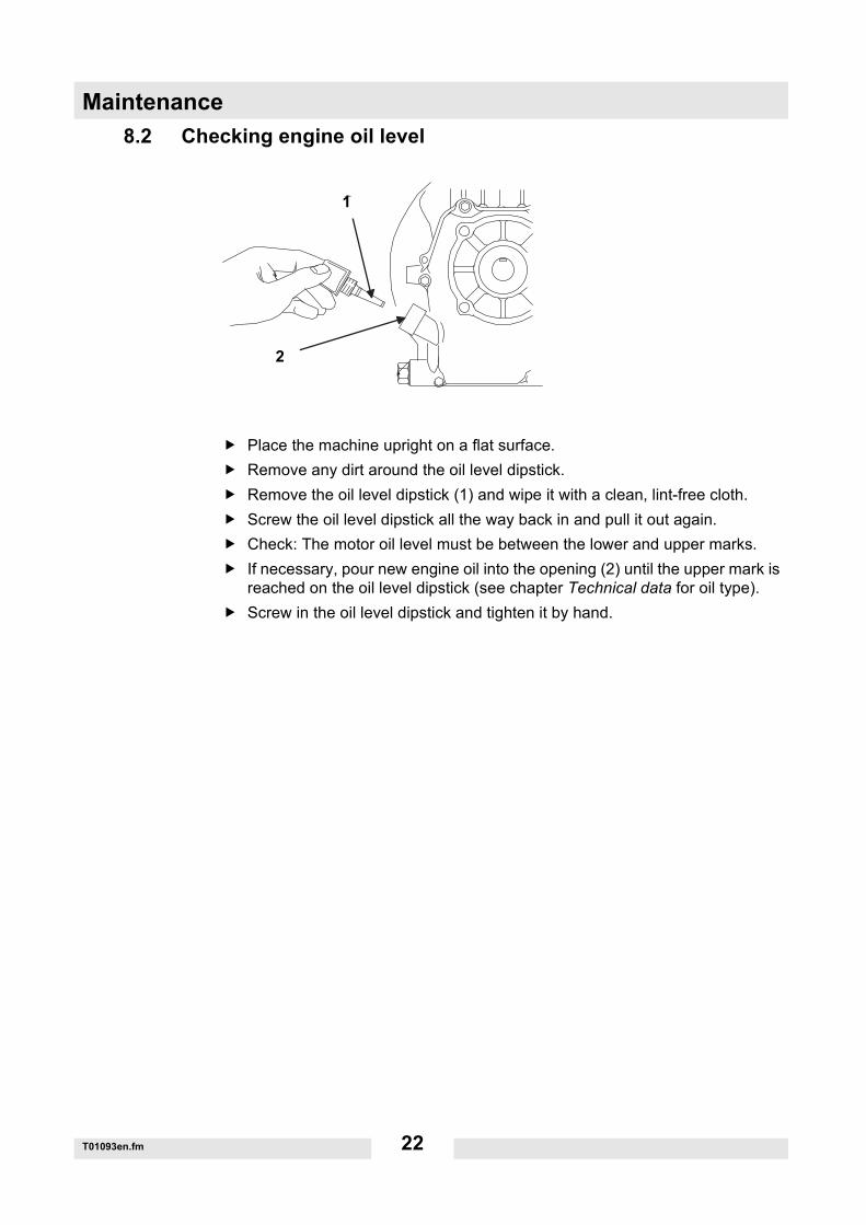
8.2 Checking engine oil level
Place the machine upright on a flat surface.Remove any dirt around the oil level dipstick.Remove the oil level dipstick (1) and wipe it with a clean, lint-free cloth.Screw the oil level dipstick all the way back in and pull it out again.Check: The motor oil level must be between the lower and upper marks.If necessary, pour new engine oil into the opening (2) until the upper mark is reached on the oil level dipstick (see chapter Technical data for oil type).Screw in the oil level dipstick and tighten it by hand.
� � � � � � � � � � �
�
�
�1
2
Maintenance
T01093en.fm 23
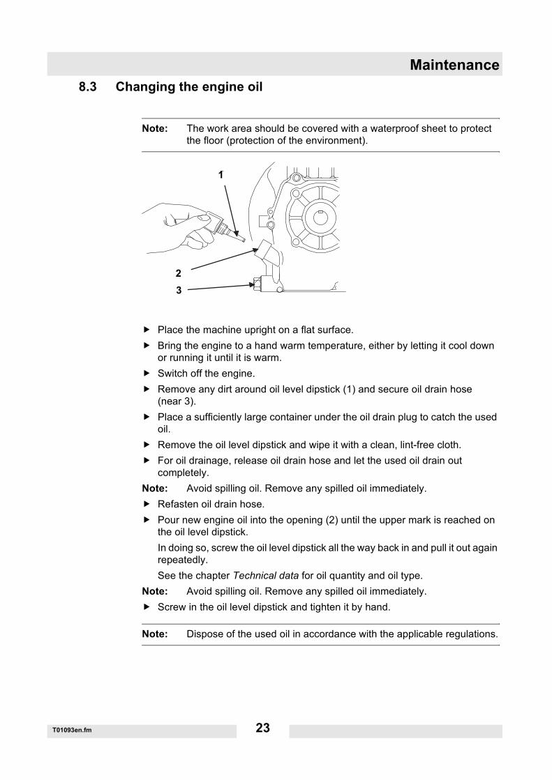
8.3 Changing the engine oil
Note: The work area should be covered with a waterproof sheet to protect the floor (protection of the environment).
Place the machine upright on a flat surface.Bring the engine to a hand warm temperature, either by letting it cool down or running it until it is warm.Switch off the engine.Remove any dirt around oil level dipstick (1) and secure oil drain hose (near 3).Place a sufficiently large container under the oil drain plug to catch the used oil.Remove the oil level dipstick and wipe it with a clean, lint-free cloth.For oil drainage, release oil drain hose and let the used oil drain out completely.
Note: Avoid spilling oil. Remove any spilled oil immediately.Refasten oil drain hose.Pour new engine oil into the opening (2) until the upper mark is reached on the oil level dipstick.In doing so, screw the oil level dipstick all the way back in and pull it out again repeatedly.See the chapter Technical data for oil quantity and oil type.
Note: Avoid spilling oil. Remove any spilled oil immediately.Screw in the oil level dipstick and tighten it by hand.
Note: Dispose of the used oil in accordance with the applicable regulations.
� � � � � � � � � � �
�
�
�1
23
Maintenance
T01093en.fm 24
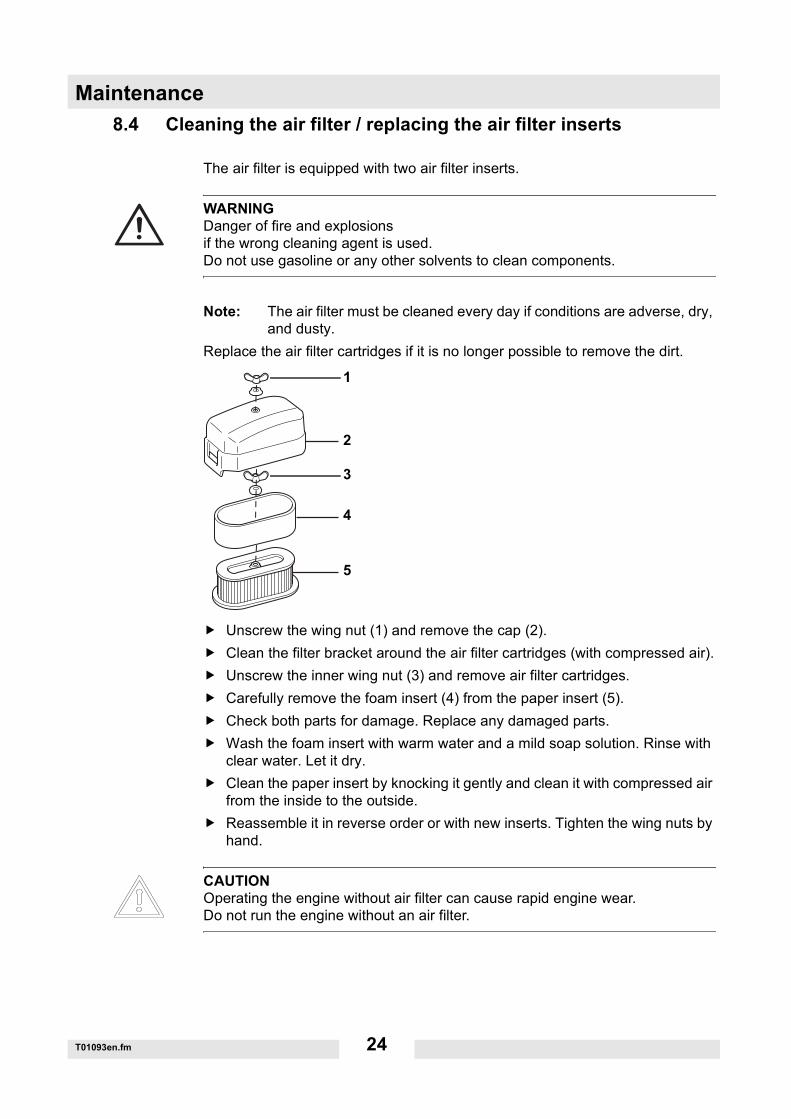
8.4 Cleaning the air filter / replacing the air filter inserts
The air filter is equipped with two air filter inserts.
Note: The air filter must be cleaned every day if conditions are adverse, dry, and dusty.
Replace the air filter cartridges if it is no longer possible to remove the dirt.
Unscrew the wing nut (1) and remove the cap (2).Clean the filter bracket around the air filter cartridges (with compressed air).Unscrew the inner wing nut (3) and remove air filter cartridges.Carefully remove the foam insert (4) from the paper insert (5).Check both parts for damage. Replace any damaged parts.Wash the foam insert with warm water and a mild soap solution. Rinse with clear water. Let it dry.Clean the paper insert by knocking it gently and clean it with compressed air from the inside to the outside.Reassemble it in reverse order or with new inserts. Tighten the wing nuts by hand.
WARNINGDanger of fire and explosionsif the wrong cleaning agent is used.Do not use gasoline or any other solvents to clean components.
CAUTIONOperating the engine without air filter can cause rapid engine wear.Do not run the engine without an air filter.
c
b
a
wc_gr000656
2
4
5
1
3
Maintenance
T01093en.fm 25
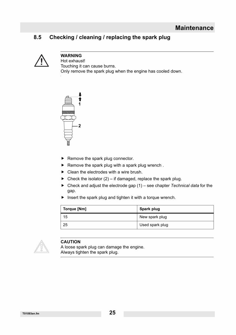
8.5 Checking / cleaning / replacing the spark plug
Remove the spark plug connector.Remove the spark plug with a spark plug wrench .Clean the electrodes with a wire brush.Check the isolator (2) – if damaged, replace the spark plug.Check and adjust the electrode gap (1) – see chapter Technical data for the gap.Insert the spark plug and tighten it with a torque wrench.
WARNINGHot exhaust!Touching it can cause burns.Only remove the spark plug when the engine has cooled down.
Torque [Nm] Spark plug
15 New spark plug
25 Used spark plug
CAUTIONA loose spark plug can damage the engine.Always tighten the spark plug.
1
2
Maintenance
T01093en.fm 26
8.6 Checking exciter V-belt
Remove V-belt protector.Check exciter V-belt for signs of damage. Replace damaged exciter V-belts.Check tension.Screw the V-belt protector back on and use a torque wrench to tighten it to 10 Nm.
8.7 Changing exciter V-belt
Remove V-belt protector.Remove 3 screws on engine V-belt disc.Remove outer half of V-belt disc.Change exciter V-belt.Press the V-belt downward into the exciter box and thread the V-belt pulley.
Note: Attach the V-belt within both roll pins.Attach clutch drum and tighten with 3 screws to 10 Nm.
Note: Turn the clutch drum in the process to avoid pinching the V-belt.Remount V-belt protector. Tighten screws with a torque wrench to 10 Nm.
8.8 Checking / filling hydraulic oil level
Vertically set guide handle head and lock into place.Press the control handle in the forward movement position.Remove any dirt around the filler hole.Open the filler hole (1).Check: Oil level must reach upper edge of the gear.If necessary, fill with new hydraulic oil through the filler hole up to the upper edge of the gear (see chapter Technical data for oil type).Close the filler hole and tighten.
Note: The hydraulic control is self-bleeding.
Maintenance
T01093en.fm 27
8.9 Checking exciter oil level
Place the machine upright on a flat surface.Remove any dirt around the filler hole.Open filler hole.Check: Oil level must reach the start of the thread of the filler hole.If necessary, fill exciter oil through the filler hole.
Note: For easier filling, use a funnel.Close filler hole and use a torque wrench to tighten it to 100 Nm.
8.10 Changing exciter oil
Note: The work area should be covered with a waterproof sheet to protect the floor (protection of the environment).
Bring the engine to a hand warm temperature, either by letting it cool down or running it until it is warm.Switch off the engine.Remove any dirt around the filler hole.
Tilt machine slightly and support it.Place a sufficiently large container under the oil drain plug to catch the used oil.
Note: Avoid spilling oil. Remove any spilled oil immediately.Open oil drain plug.Tilt machine and let used oil drain out completely.Place the machine upright on a flat surface.Fill with new exciter oil through the filler hole to the start of the thread.For oil quantity see Technical Data.Screw the oil drain plug back in and use a torque wrench to tighten it to 100 Nm.
Note: Dispose of the used oil in accordance with the applicable regulations.
WARNINGDanger through overturning.If the machine overturns, it can cause severe injury such as crushing. Only use suitable and tested hoisting gear and lifting tackle of sufficient lifting capacity.Turn off machine in a stable position.
Malfunction
T01094en.fm 28
9. Malfunction
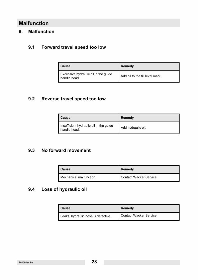
9.1 Forward travel speed too low
9.2 Reverse travel speed too low
9.3 No forward movement
9.4 Loss of hydraulic oil
Cause Remedy
Excessive hydraulic oil in the guide handle head. Add oil to the fill level mark.
Cause Remedy
Insufficient hydraulic oil in the guide handle head. Add hydraulic oil.
Cause Remedy
Mechanical malfunction. Contact Wacker Service.
Cause Remedy
Leaks, hydraulic hose is defective. Contact Wacker Service.
Malfunction
T01094en.fm 29
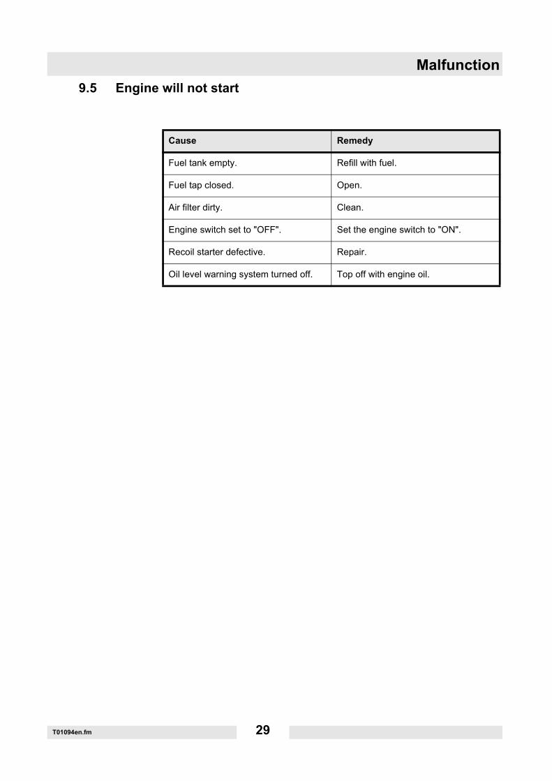
9.5 Engine will not start
Cause Remedy
Fuel tank empty. Refill with fuel.
Fuel tap closed. Open.
Air filter dirty. Clean.
Engine switch set to "OFF". Set the engine switch to "ON".
Recoil starter defective. Repair.
Oil level warning system turned off. Top off with engine oil.

Malfunction
T01094en.fm 30
C0036007en.fmPlea
se k
eep
this
doc
umen
t in
a sa
fe p
lace
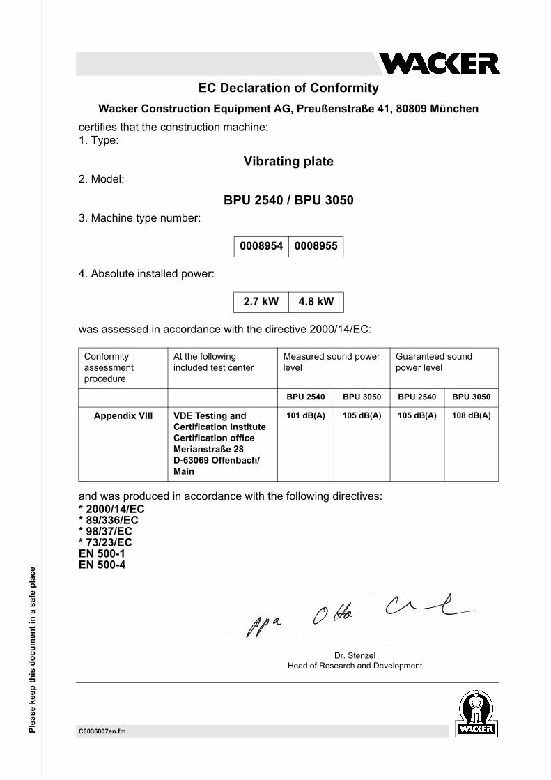
EC Declaration of ConformityWacker Construction Equipment AG, Preußenstraße 41, 80809 München
certifies that the construction machine:1. Type:
Vibrating plate2. Model:
BPU 2540 / BPU 30503. Machine type number:
4. Absolute installed power:
was assessed in accordance with the directive 2000/14/EC:
and was produced in accordance with the following directives:* 2000/14/EC* 89/336/EC* 98/37/EC* 73/23/ECEN 500-1EN 500-4
0008954 0008955
2.7 kW 4.8 kW
Conformity assessment procedure
At the following included test center
Measured sound power level
Guaranteed sound power level
BPU 2540 BPU 3050 BPU 2540 BPU 3050
Appendix VIII VDE Testing and Certification InstituteCertification officeMerianstraße 28D-63069 Offenbach/Main
101 dB(A) 105 dB(A) 105 dB(A) 108 dB(A)
Dr. StenzelHead of Research and Development


DIN EN ISO 9001 CERTIFICATE

Wacker Construction Equipment AG - Preußenstraße 41 - 80809 München - Tel.: +49-(0)89-3 54 02-0 - Fax: +49-(0)89-3 54 02-390Wacker Corporation - P.O. Box 9007 - Menomonee Falls, WI 53052-9007 - Tel.: +1-(1)(262)-255-0500 - Fax: +1-(1)(262)-255-0550 - Tel.: (800)770-0957Wacker Asia Pacific Operations-Skyline Tower, Suite 2303, 23/F, 39 Wang Kwong Road, Kowloon Bay, Hong Kong-Tel.: +852 2406 6032-Fax: +852 2406 6021