BoxyBot, the fish robot
47
BoxyBot, the fish robot Design and realization EPFL - Semester Project 27 June 2005 Author : Daisy Lachat Supervisor : Alessandro Crespi Professor : Auke Jan Ijspeert
Transcript of BoxyBot, the fish robot
BoxyBot, the fish robotDesign and realization
EPFL - Semester Project
27 June 2005
Author : Daisy Lachat
Supervisor : Alessandro Crespi
Professor : Auke Jan Ijspeert
Abstract
The world of fishes is extraordinary diversified: each fish has evolved to adapt efficiently toits environment. Despite that fact, fish propulsion systems isn’t used in common applica-tions. However some universities are studying the possibility to develop better and noiselesspropulsion systems for autonomous underwater vehicles with fishlike locomotion.
The review of fish robots shows that cruising has been already studied with success butthe autonomy is always restrained. Maneuvering has been less studied.
Amphibot II modules are used to build the fish robot: the most adapted swimming modeis labriform or ostraciiform because it don’t required a good hydrodynamic profile.
The fish robot, named BoxyBot in reference to the Boxfish, is 0.25 m long and can swimup to 0.37 m/s, the minimal radius of turning observed is 0.13 m. The robot can dive, goforwards and backwards, swim on the side and do spins. Relations between forward speed,amplitude and frequency of fin’s oscillations has been characterized.
Contents
1 Aim of the project 3
2 State of the art 42.1 Fishes’ anatomy . . . . . . . . . . . . . . . . . . . . . . . . . . . . . . . . . . 42.2 Review of fish swimming modes . . . . . . . . . . . . . . . . . . . . . . . . . . 52.3 Review of fish robots . . . . . . . . . . . . . . . . . . . . . . . . . . . . . . . . 7
3 Some possible configurations 123.1 Amphibot II modules . . . . . . . . . . . . . . . . . . . . . . . . . . . . . . . 123.2 Carangiform mode . . . . . . . . . . . . . . . . . . . . . . . . . . . . . . . . . 133.3 Ostraciiform/Labriform mode . . . . . . . . . . . . . . . . . . . . . . . . . . . 13
4 Realization of BoxyBot 164.1 Mechanical design . . . . . . . . . . . . . . . . . . . . . . . . . . . . . . . . . 164.2 Electronical design . . . . . . . . . . . . . . . . . . . . . . . . . . . . . . . . . 164.3 Software . . . . . . . . . . . . . . . . . . . . . . . . . . . . . . . . . . . . . . . 18
5 Performances 215.1 Forward speed . . . . . . . . . . . . . . . . . . . . . . . . . . . . . . . . . . . 215.2 Turning . . . . . . . . . . . . . . . . . . . . . . . . . . . . . . . . . . . . . . . 265.3 Other motions . . . . . . . . . . . . . . . . . . . . . . . . . . . . . . . . . . . 285.4 Trajectories’ follow . . . . . . . . . . . . . . . . . . . . . . . . . . . . . . . . . 29
6 Future work 31
7 Conclusion 32
A Mechanical drawings 33
B Software 34B.1 PIC’s program . . . . . . . . . . . . . . . . . . . . . . . . . . . . . . . . . . . 34B.2 Matlab . . . . . . . . . . . . . . . . . . . . . . . . . . . . . . . . . . . . . . . . 35B.3 RS232 interface . . . . . . . . . . . . . . . . . . . . . . . . . . . . . . . . . . . 36
C Web sites of fish robots 37
D Translation english-french of fishes’ vocabulary 38
1

E Electronical parts 39E.1 Control board Amphibot II - body module . . . . . . . . . . . . . . . . . . . 39E.2 Power board Amphibot II - body module . . . . . . . . . . . . . . . . . . . . 40E.3 Power board Amphibot I - head module . . . . . . . . . . . . . . . . . . . . . 41E.4 Development board for PIC16f876A . . . . . . . . . . . . . . . . . . . . . . . 42
F motor control register summary [15] 43
2
Chapter 1
Aim of the project
The goal of this project is to realize an autonomous fish robot able to move itself in water in3 dimensions. It is intended to use amphibot II modules developed at the BIRG1.
The principal guide line is:
• Review of fish swimming modes
• Review of fish robots
• Study of different possibilities to build a fish robot with amphibot II modules
• Realization and characterization of fins: maneuverability and speed
• Trajectories’ follow
1Biologically Inspired Robotics Group
3
Chapter 2
State of the art
2.1 Fishes’ anatomy
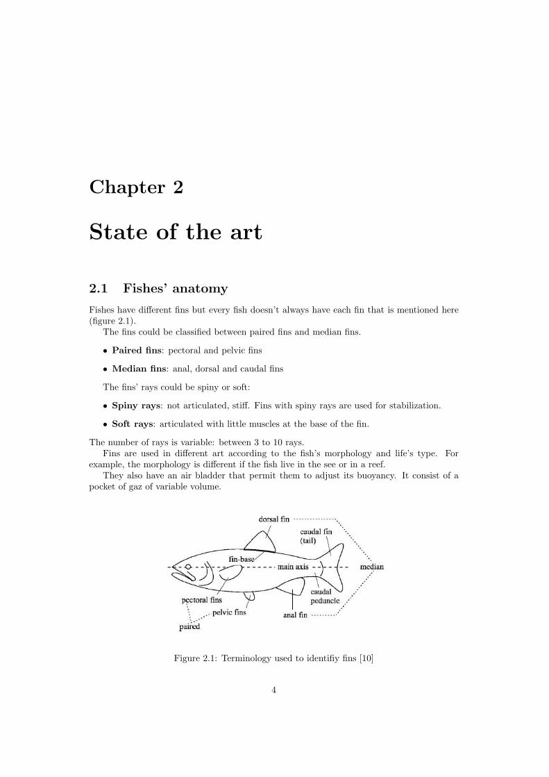
Fishes have different fins but every fish doesn’t always have each fin that is mentioned here(figure 2.1).
The fins could be classified between paired fins and median fins.
• Paired fins: pectoral and pelvic fins
• Median fins: anal, dorsal and caudal fins
The fins’ rays could be spiny or soft:
• Spiny rays: not articulated, stiff. Fins with spiny rays are used for stabilization.
• Soft rays: articulated with little muscles at the base of the fin.
The number of rays is variable: between 3 to 10 rays.Fins are used in different art according to the fish’s morphology and life’s type. For
example, the morphology is different if the fish live in the see or in a reef.They also have an air bladder that permit them to adjust its buoyancy. It consist of a
pocket of gaz of variable volume.
Figure 2.1: Terminology used to identifiy fins [10]
4
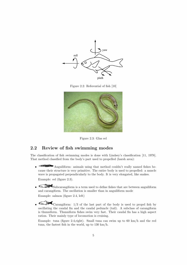
Figure 2.2: Referential of fish [10]
Figure 2.3: Glas eel
2.2 Review of fish swimming modes
The classification of fish swimming modes is done with Lindsey’s classification [11, 1978].That method classified from the body’s part used to propelled (harsh area):
• Anguiliform: animals using that method couldn’t really named fishes be-cause their structure is very primitive. The entire body is used to propelled: a musclewave is propagated perpendicularly to the body. It is very elongated, like snakes.
Example: eel (figure 2.3).
• Subcarangiform is a term used to define fishes that are between anguiliformand carangiform. The oscillation is smaller than in anguiliform mode
Example: salmon (figure 2.4, left)
• Carangiform: 1/3 of the last part of the body is used to propel fish byoscillating the caudal fin and the caudal peduncle (tail). A subclass of carangiformis thunniform. Thunniform fishes swim very fast. Their caudal fin has a high aspectration. Their mainly type of locomotion is cruising.
Example: tuna (figure 2.4,right). Small tuna can swim up to 60 km/h and the redtuna, the fastest fish in the world, up to 130 km/h.
5
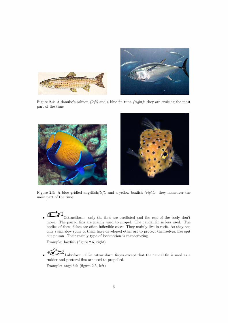
Figure 2.4: A danube’s salmon (left) and a blue fin tuna (right): they are cruising the mostpart of the time
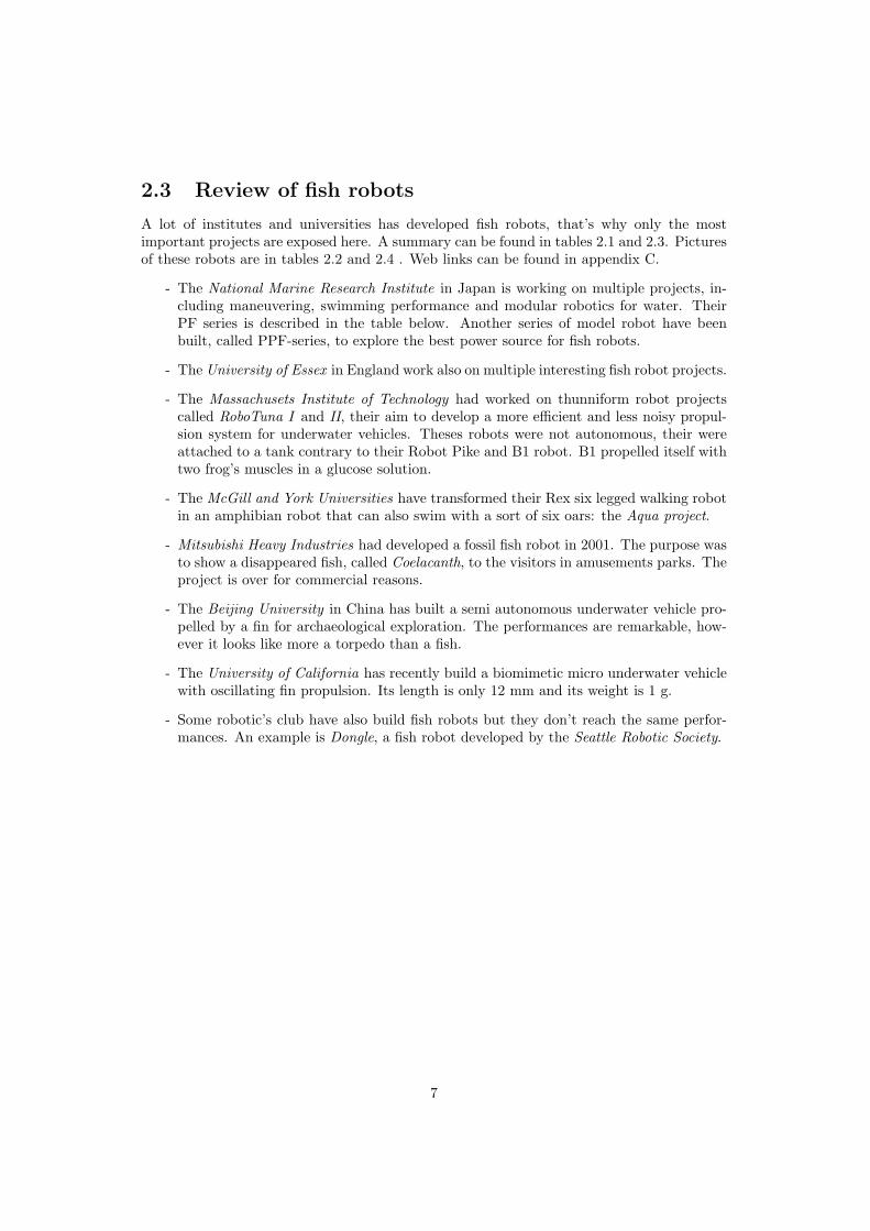
Figure 2.5: A blue gridled angelfish(left) and a yellow boxfish (right): they maneuver themost part of the time
• Ostraciiform: only the fin’s are oscillated and the rest of the body don’tmove. The paired fins are mainly used to propel. The caudal fin is less used. Thebodies of these fishes are often inflexible cases. They mainly live in reefs. As they canonly swim slow some of them have developed other art to protect themselves, like spitout poison. Their mainly type of locomotion is manoeuvring.
Example: boxfish (figure 2.5, right)
• Labriform: alike ostraciiform fishes except that the caudal fin is used as arudder and pectoral fins are used to propelled.
Example: angelfish (figure 2.5, left)
6
2.3 Review of fish robots
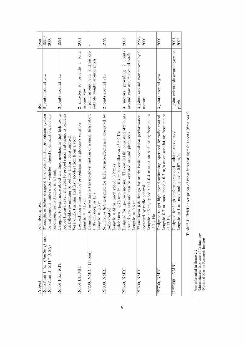
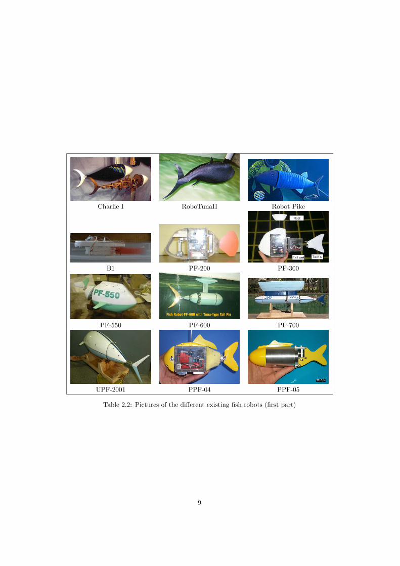
A lot of institutes and universities has developed fish robots, that’s why only the mostimportant projects are exposed here. A summary can be found in tables 2.1 and 2.3. Picturesof these robots are in tables 2.2 and 2.4 . Web links can be found in appendix C.
- The National Marine Research Institute in Japan is working on multiple projects, in-cluding maneuvering, swimming performance and modular robotics for water. TheirPF series is described in the table below. Another series of model robot have beenbuilt, called PPF-series, to explore the best power source for fish robots.
- The University of Essex in England work also on multiple interesting fish robot projects.
- The Massachusets Institute of Technology had worked on thunniform robot projectscalled RoboTuna I and II, their aim to develop a more efficient and less noisy propul-sion system for underwater vehicles. Theses robots were not autonomous, their wereattached to a tank contrary to their Robot Pike and B1 robot. B1 propelled itself withtwo frog’s muscles in a glucose solution.
- The McGill and York Universities have transformed their Rex six legged walking robotin an amphibian robot that can also swim with a sort of six oars: the Aqua project.
- Mitsubishi Heavy Industries had developed a fossil fish robot in 2001. The purpose wasto show a disappeared fish, called Coelacanth, to the visitors in amusements parks. Theproject is over for commercial reasons.
- The Beijing University in China has built a semi autonomous underwater vehicle pro-pelled by a fin for archaeological exploration. The performances are remarkable, how-ever it looks like more a torpedo than a fish.
- The University of California has recently build a biomimetic micro underwater vehiclewith oscillating fin propulsion. Its length is only 12 mm and its weight is 1 g.
- Some robotic’s club have also build fish robots but they don’t reach the same perfor-mances. An example is Dongle, a fish robot developed by the Seattle Robotic Society.
7
Pro
ject
brie
fde
scri
ptio
ndo
faye
arR
oboT
una
I(o
rC
harlie
I)an
dR
oboT
una
II,M
ITb
(USA
)T
hunn
ifor
mfis
hes
desi
gned
tode
velo
pbe
tter
prop
ulsi
onsy
stem
for
auto
nom
ous
unde
rwat
erve
hicl
es.
Spee
dop
tim
izat
ion,
not
au-
tono
mou
s,te
stat
tach
edin
ata
nk.
8jo
ints
arou
ndya
w19
95/
2000
Rob
otP
ike,
MIT
Des
igne
dto
lear
nm
ore
abou
tth
eflu
idm
echa
nics
that
fish
use
topr
opel
them
selv
esin
the
goal
topr
opel
smal
laut
onom
ous
vehi
cles
via
fish-
like
swim
min
gto
redu
ceen
ergy
cons
umpt
ion.
Ver
yqu
ick
turn
ing
and
fast
acce
lera
tion
from
ast
op.
3jo
ints
arou
ndya
w19
94
Rob
otB
1,M
ITU
sere
alfr
og’s
mus
cles
for
prop
ulsi
onin
agl
ucos
e’s
solu
tion
Len
gth:≈
0.15
m2
mus
cles
topr
ovid
e1
join
tar
ound
yaw
2001
PF20
0,N
MR
Ic(J
apan
)D
esig
ned
toin
vest
igat
eth
eup
-dow
nm
otio
nof
asm
allfi
shro
bot:
≈35
cmde
epin
15s
Len
gth:≈
0.3
m
1jo
int
arou
ndya
wan
dan
ori-
enta
ble
wei
ght
arou
ndpi
tch
-
PF30
0,N
MR
ISe
abr
eam
fish
desi
gned
for
high
turn
-per
form
ance
,op
erat
edby
radi
oco
ntro
lLen
gth:
0.34
m,m
axisp
eed:
0.2
m/s
quic
ktu
rn:�
75m
min
10s
atan
osci
llati
onof
2.2
Hz
2jo
ints
arou
ndya
w19
99
PF55
0,N
MR
ID
esig
ned
forup
-dow
nm
otio
n.T
heca
udal
fin,c
onsi
sted
of2
join
tsar
ound
yaw
axis
and
can
beor
ient
edar
ound
pitc
hax
isLen
gth:≈
0.6
m
3m
otor
spr
ovid
ing
2jo
ints
arou
ndya
wan
d2
arou
ndpi
tch
2003
PF60
0,N
MR
IT
hunn
ifor
mfis
hde
sign
for
stud
yba
sic
prop
ulsi
onpe
rfor
man
ce,
oper
ated
byra
dio
cont
rol
Len
gth:
0.6
m,
spee
d:
0.1-
0.4
m/s
atan
osci
llati
ngfr
eque
ncie
sof
1-4
Hz
3jo
ints
arou
ndya
wm
oved
by2
mot
ors
1998
-20
00
PF70
0,N
MR
ID
esig
ned
toge
thi
ghsp
eed
swim
min
g,op
erat
edby
radi
oco
ntro
lLen
gth:
0.7
m,m
axsp
eed
:0.
7m
/sat
anos
cilla
ting
freq
uenc
ies
of12
Hz
3jo
ints
arou
ndya
w20
00
UP
F20
01,N
MR
ID
esig
ned
for
high
perf
orm
ance
san
dm
ulti
-pur
pose
-use
dLen
gth:≈
1m
,m
axim
alsp
eed
:0.
97m
/s1
join
tor
ient
able
arou
ndya
wor
pitc
h20
01-
2002
Tab
le2.
1:B
rief
desc
ript
ion
ofm
ost
inte
rest
ing
fish
robo
ts(fi
rst
part
)
ase
ere
fere
ntialin
figure
2.2
bM
ass
ach
use
tsIn
stitute
ofTec
hnolo
gy
cN
ationalM
ari
ne
Res
earc
hIn
stitut
8
Charlie I RoboTunaII Robot Pike
B1 PF-200 PF-300
PF-550 PF-600 PF-700
UPF-2001 PPF-04 PPF-05
Table 2.2: Pictures of the different existing fish robots (first part)
9
Pro
ject
brie
fde
scri
ptio
ndo
fye
arG
1,G
2,G
3,G
4,G
5an
dM
T1,
Uni
vers
ity
ofE
ssex
(UK
)D
iffer
ent
auto
nom
ous
fish
robo
tsth
atsw
ims
like
real
-fish
esan
dna
viga
tes
byth
emse
lves
-20
03-
2005
Aqu
a,M
cGill
and
Yor
kU
nive
r-si
tyA
mph
ibio
usro
bot
deve
lope
dfr
omth
eR
exsi
xle
gged
wal
king
ro-
bot
6jo
ints
arou
ndth
epi
tch
axis
2004
Coe
laca
nth
fish,
MH
IaFo
ssil
fish
for
amus
emen
tpa
rks
and
aqua
rium
s.C
ontr
olle
dby
anex
tern
alP
C.P
roje
ctgi
ven
upfo
rco
mm
erci
alre
ason
s.Len
gth:
0.7
m,w
eigh
t:
12kg
not
com
mun
icat
ebu
ta
lot
ofjo
ints
and
fins
2001
SPC
-II,
BU
AA
ban
dSI
Ac
(Chi
ne)
Sem
i-au
tono
mou
sun
derw
ater
vehi
cle
for
arch
aeol
ogic
alex
plo-
rati
onLen
gth:
1.23
m,m
axsp
eed
:1.
5m
/s
2jo
ints
arou
ndya
w,p
erha
psbe
-tw
een
0an
d2
arou
ndpi
tch
2004
Don
gle,
SRSd
Des
igne
dfo
ram
usem
ent.
Aut
onom
ous
Len
gth:
0.6
m,sp
eed
:≈
0.06
m/s
,w
eigh
t:2.
3kg
2jo
ints
arou
ndya
w-
BA
SS-I
I,N
.K
ato
(Jap
an)[
6]R
ende
zvou
san
ddo
ckin
gw
ith
anun
derw
ater
post
inw
ater
cur-
rent
.U
seof
2pe
ctor
alfin
sto
stab
ilize
the
robo
t.2
pect
oral
fins:
join
tsar
ound
yaw
axis
2000
Box
fish,
Uni
vers
ity
ofC
alifo
rnia
[1]
mic
rove
hicl
eco
ntro
lled
byP
ZT
bim
orph
actu
ator
sLen
gth:
12m
mw
eigh
t:1
g2
join
tsar
ound
roll
and
1jo
int
arou
ndya
wA
pril
2005
Tab
le2.
3:B
rief
desc
ript
ion
ofm
ost
inte
rest
ing
fish
robo
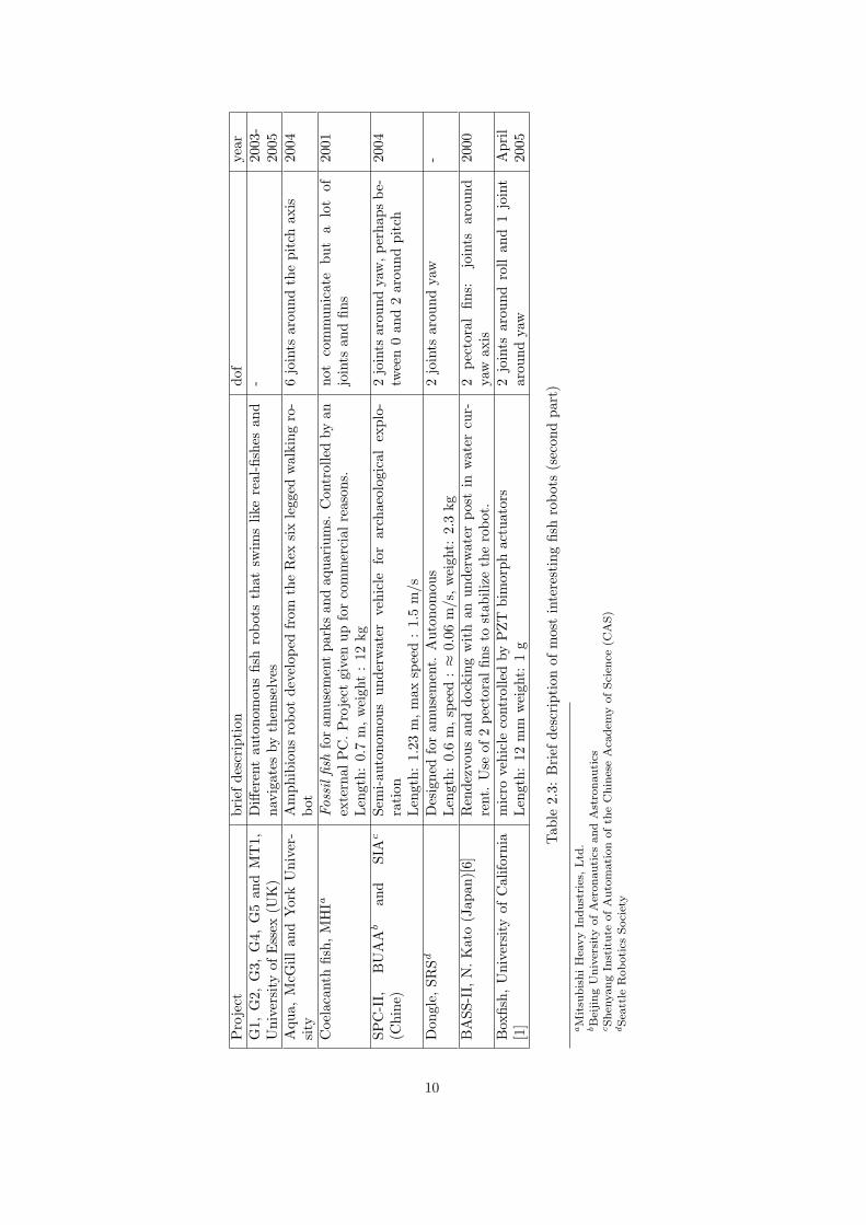
ts(s
econ
dpa
rt)
aM
itsu
bis
hiH
eavy
Indust
ries
,Ltd
.bB
eijing
Univ
ersi
tyofA
eronautics
and
Ast
ronauti
cscShen
yang
Inst
itute
ofA
uto
mation
ofth
eC
hin
ese
Aca
dem
yofSci
ence
(CA
S)
dSea
ttle
Robotics
Soci
ety
10
MT1 G1 G2
G3 G4 G5
Coelacanth dongle SPC-II
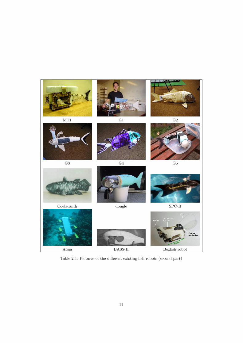
Aqua BASS-II Boxfish robot
Table 2.4: Pictures of the different existing fish robots (second part)
11
Chapter 3
Some possible configurations
3.1 Amphibot II modules
The amphibot II modules were designed at the BIRG in 2005, the first modules were availablein may 2005. The principle is that each module is power supply and mechanically independentfrom another and can be easily replaced in case of damage. The modules’ density is nearwater’s density. Their is two type of modules: head and body modules.
The body module contains one motor. The head module contains two motors that areperpendicular to the body’s motor. They communicate with I2C protocol. The motor controlmodule was developed at the ASL1 (appendix F).
For that project it was intended to use these modules and explore the different possibilitiesto build a fish robot with minimal modifications to modules. The challenge is to demonstratethe modularity and the capacity to work in water.
1Autonomous System Lab - EPFL
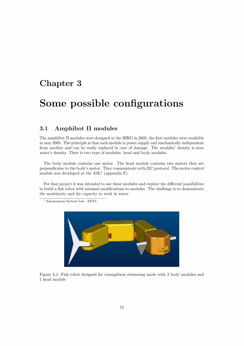
Figure 3.1: Fish robot designed for carangiform swimming mode with 3 body modules and1 head module
12
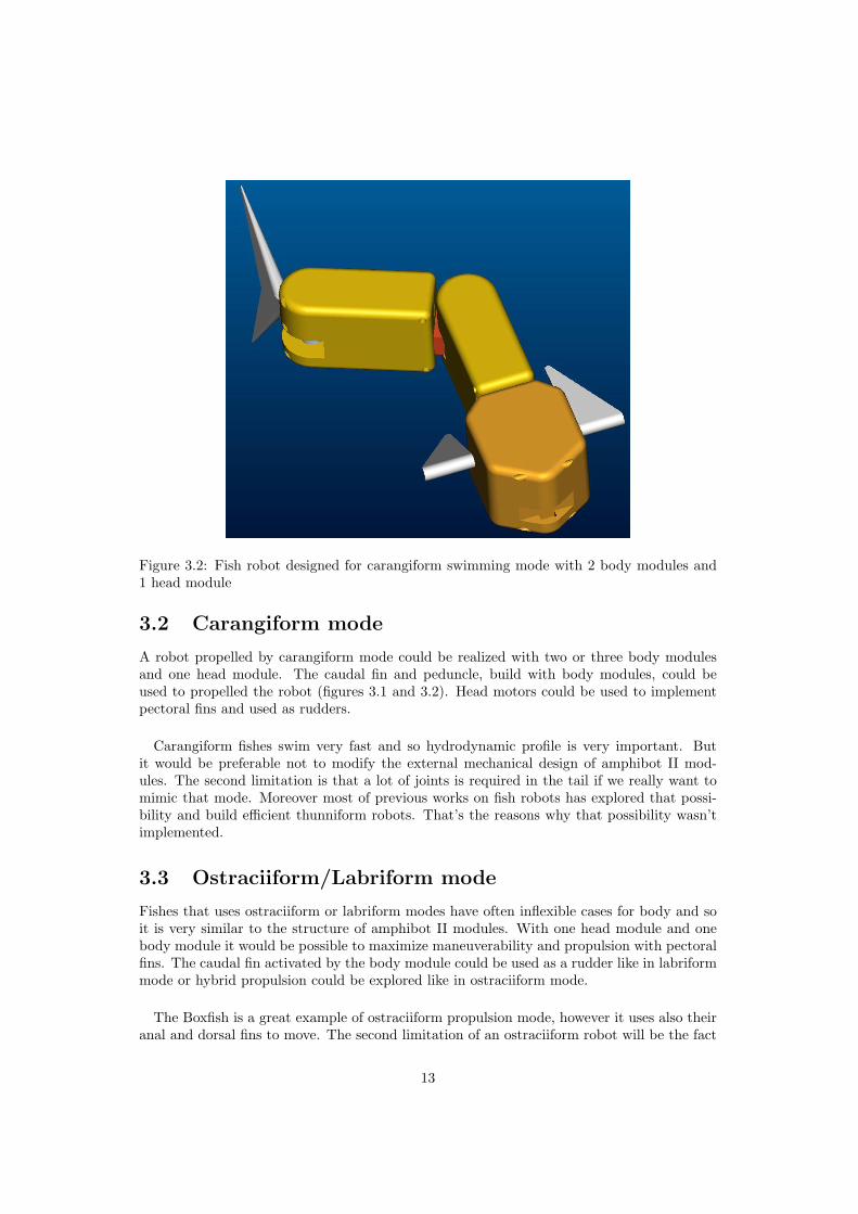
Figure 3.2: Fish robot designed for carangiform swimming mode with 2 body modules and1 head module
3.2 Carangiform mode
A robot propelled by carangiform mode could be realized with two or three body modulesand one head module. The caudal fin and peduncle, build with body modules, could beused to propelled the robot (figures 3.1 and 3.2). Head motors could be used to implementpectoral fins and used as rudders.
Carangiform fishes swim very fast and so hydrodynamic profile is very important. Butit would be preferable not to modify the external mechanical design of amphibot II mod-ules. The second limitation is that a lot of joints is required in the tail if we really want tomimic that mode. Moreover most of previous works on fish robots has explored that possi-bility and build efficient thunniform robots. That’s the reasons why that possibility wasn’timplemented.
3.3 Ostraciiform/Labriform mode
Fishes that uses ostraciiform or labriform modes have often inflexible cases for body and soit is very similar to the structure of amphibot II modules. With one head module and onebody module it would be possible to maximize maneuverability and propulsion with pectoralfins. The caudal fin activated by the body module could be used as a rudder like in labriformmode or hybrid propulsion could be explored like in ostraciiform mode.
The Boxfish is a great example of ostraciiform propulsion mode, however it uses also theiranal and dorsal fins to move. The second limitation of an ostraciiform robot will be the fact
13
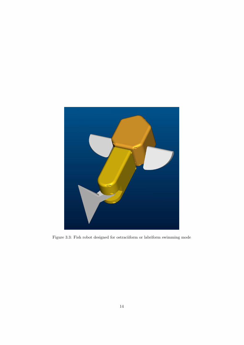
Figure 3.3: Fish robot designed for ostraciiform or labriform swimming mode
14

that pectoral fins have only each one degree of freedom in place of five to ten per pectoralfins for the Boxfish.
15

Chapter 4
Realization of BoxyBot
The fish robot realized is inspired by the BoxFish and so were baptized BoxyBot. It use onlytwo modules: one head and one body module. The configuration of BoxyBot is visible infigure 4.1
4.1 Mechanical design
Fins Fins are made of plate of polymer (PE or rubber). They are fixed to the moduleswith intermediate parts to provide easy change of the fins: fins are maintained with two pins.Remark that the attachement part for caudal fin is the same part as the original attach ofamphibot II modules with little modifications after injection, the same mould can so be used.Fins can be made with different thickness up to 4 mm. If the groove is larger than necessaryan additional part is put. See appendix A for mechanical drawings.
fins realized aspect ration surface [cm2]caudal fin 2.9 35small pectoral fins 0.6 25 x 2 finsbig pectoral fins 0.6 50 x 2 fins
The two caudal fins and the four paired of pectoral fins realized are visible in figure 4.2. Thedimensions are in table above. Fins made of rubber will be named ”flexible” in the rest ofthe report.
Buoyancy The final density is bigger than water’s density so it sinks. The robot is alsonot enough vertically distribute. So a mass is added under the body and a float (expansedPS) above.
Final robot’s length is 25 [cm] with the caudal fin.
4.2 Electronical design
Control Previously, amphibot I modules were controlled by an outside computer. Themodules were connected with a cable and were only power autonomous. In goal to preventinfluence of the cable to the dynamic of the future fish robot a PIC16f876A is added onthe electronic board of the body module (appendix E.1). It is used as the master for I2Ccommunication.
16
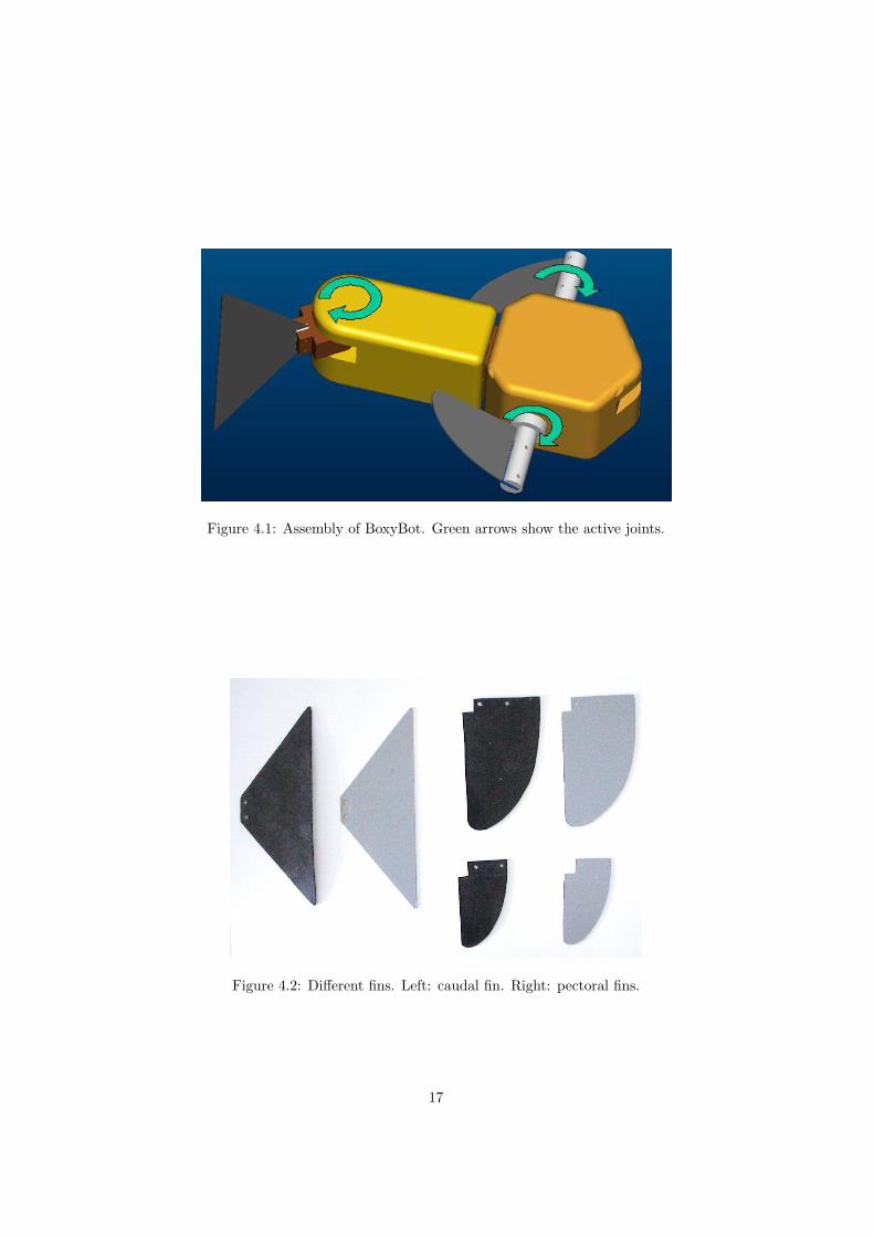
Figure 4.1: Assembly of BoxyBot. Green arrows show the active joints.
Figure 4.2: Different fins. Left: caudal fin. Right: pectoral fins.
17
Magnetic contact To stop power supply from batteries without opening the module, amagnetic contact is added in the power board of the body module (appendix E.2). However,the module have to be opened to program the PIC and to recharge batteries.
Because the electronic board of the head module were not available, the electronic boardof Amphibot I is used for the head. To keep the possibility to stop power supply, littlemodifications were made on that board (appendix E.3).
4.3 Software
The PIC is programmed in language C with CCS compiler and an In Circuit Debugger (ICD)from microchip [12]. Motors are controlled in position without specific profile of velocity, thesignal compute by the program is a sinusoidal signal, a lookup table is used to compute thatsine and time is incremented in an interrupt.
Series of motions Because of the fact that the robot have to be dry, open and repro-grammed each time that we want to test another program, it is possible to enter a table ofamplitude, frequency, phase, offset and sequences duration for testing a series of motions.
The flow charts of the program are visible in figures 4.3 to 4.6.
Development and graphical visualization An external board can be used to test theprogram (appendix E.4). That board have the same PIC that will be the master and replacethe PIC in the fish. When using that external board it is important to be sure that thecontroller in the fish don’t act as a master. So it is recommended to erase it while using theexternal board.
When using the external board, it is possible to define a constant(GRAPH) in the headerfile to visualize the movement of the fins. The values of the positions of the three fins will besent by RS232 communication. A program on the pc will take the values and write them ina text file, easily usable with Matlab. The pc software is in appendix B.3 and matlab codein B.2.
18
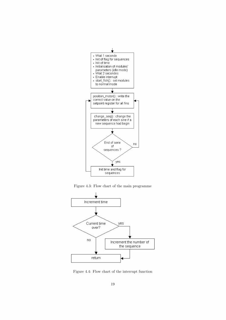
Figure 4.3: Flow chart of the main programme
Figure 4.4: Flow chart of the interrupt function
19
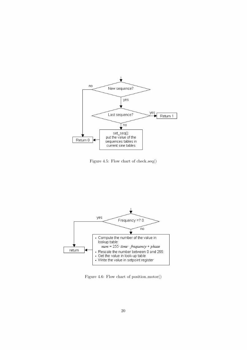
Figure 4.5: Flow chart of check seq()
Figure 4.6: Flow chart of position motor()
20
Chapter 5
Performances
The robot has no sensors and so it is very difficult to control its trajectory. Explore themaneuverability is possible but characterize isn’t without any feedback. Speed of the robotis characterized and turning is measured very approximately. Some other motions wereexplored like diving, do spin or move backwards.
5.1 Forward speed
Speed is a function of amplitude and frequency of the fins’ oscillations. It depends also on alot of parameters like aspect ratio, stiffness or surface of the fins.
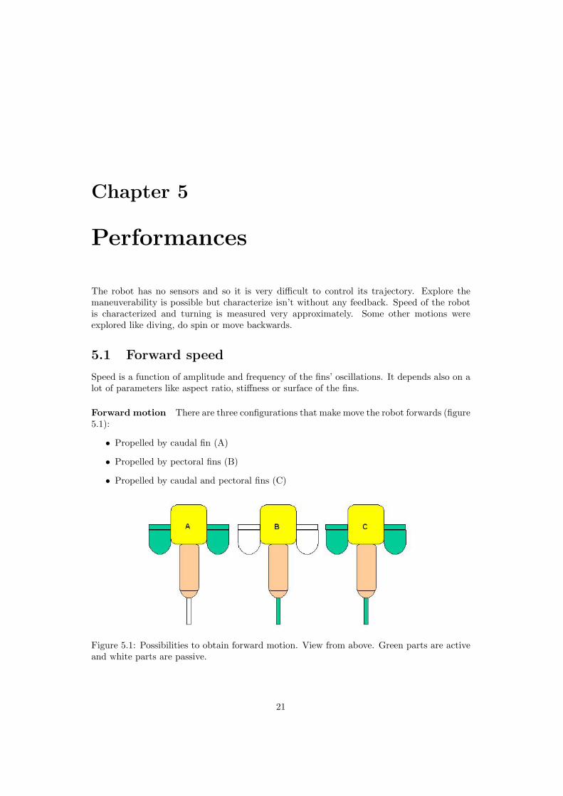
Forward motion There are three configurations that make move the robot forwards (figure5.1):
• Propelled by caudal fin (A)
• Propelled by pectoral fins (B)
• Propelled by caudal and pectoral fins (C)
Figure 5.1: Possibilities to obtain forward motion. View from above. Green parts are activeand white parts are passive.
21
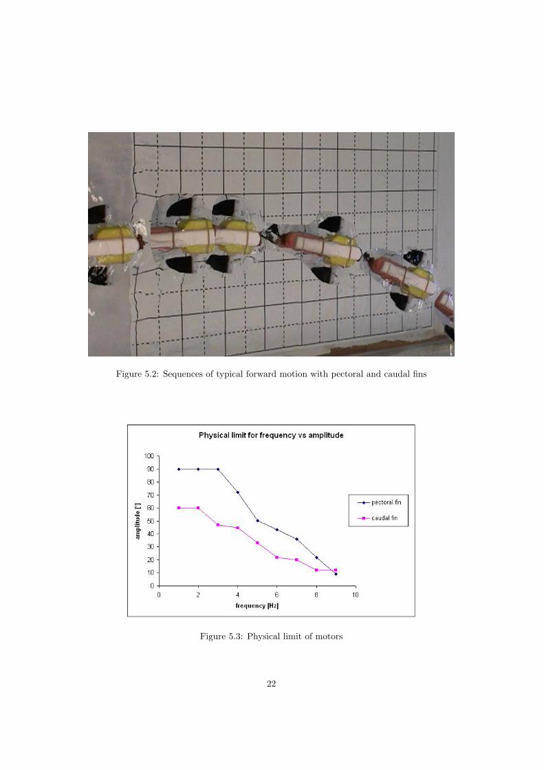
Figure 5.2: Sequences of typical forward motion with pectoral and caudal fins
Figure 5.3: Physical limit of motors
22
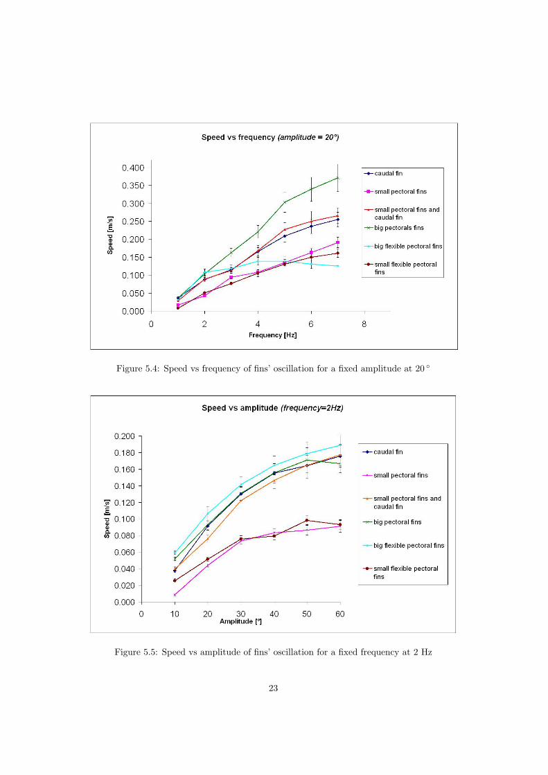
Figure 5.4: Speed vs frequency of fins’ oscillation for a fixed amplitude at 20 ◦
Figure 5.5: Speed vs amplitude of fins’ oscillation for a fixed frequency at 2 Hz
23
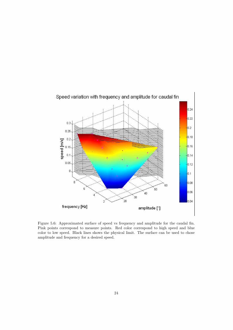
Figure 5.6: Approximated surface of speed vs frequency and amplitude for the caudal fin.Pink points correspond to measure points. Red color correspond to high speed and bluecolor to low speed. Black lines shows the physical limit. The surface can be used to choseamplitude and frequency for a desired speed.
24
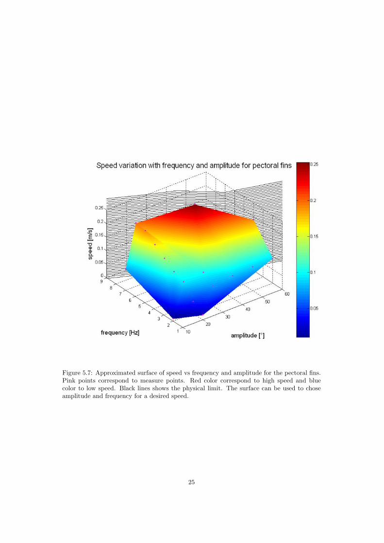
Figure 5.7: Approximated surface of speed vs frequency and amplitude for the pectoral fins.Pink points correspond to measure points. Red color correspond to high speed and bluecolor to low speed. Black lines shows the physical limit. The surface can be used to choseamplitude and frequency for a desired speed.
25

Measure of the speed As explained before, the robot never goes straight. So it is nec-essary to measure distance in two directions. The curve traveled is then approximated to aline. In that goal, a video camera is used to film the robot from above. A squared paper isplaced under the aquarium to provide the possibility to measure distance. The accuracy ofmeasure is then about ±2 [cm] in both directions and ±0.08[s] for the time (video accuracy).That method provide an accuracy less than ±0.02 [m/s]. A typical measure’s sequence isshown in figure 5.2.
Physical limit The physical limit of the motors, visible in figure 5.3 is determined withoutcharge (out of the water). It is defined by the maximal values of sine parameters that themotor can follow without diminution of amplitude. The software limit is above the physicallimit.
Results The results obtained are visible in figures 5.4 to 5.7.
• Speed is proportional to frequency
• Speed is proportional to amplitude. We see a saturation that arrived near 90 ◦ becauseat that amplitude the motion is opposed to the direction of desired motion
• Use of the caudal fin get more speed than with small pectoral fins. We can also seethat using pectoral and caudal fins together in place of caudal fin only don’t provide abetter speed
• A too weak stiffness isn’t appropriate for frequencies above 2 [Hz] but can be better forsmaller frequencies.
• Speed is highly proportional to fins’ surface
5.2 Turning
The possibilities for turning are multiple (figure 5.9). There is two main phenomena thatmake the robot turn:
• Caudal’s offset shift the centre of gravity and the fins’ forces cause moments
• Hydrodynamic forces on the caudal fin
For small speed the second phenomena is negligible. In the case of the configurations Cand D at high speed, the left pectoral fin increase water’s velocity and hydrodynamic forcesare important on the caudal fin.
The measure of radius of turning isn’t very accurate because the motion of the robotcause waves that perturb it. Because of that, the curve wasn’t really a circle.
Results Radius of turning is independent of rotational speed. Each configuration prensentedin figure 5.9 have been tested and works.
• configuration A : the relation between caudal offset and radius of turning is shown infigure 5.10. The minimal radius obtained is about 20 cm. The maximal value thatcould be measured is about 60 cm because of the dimension of the aquarium.
26
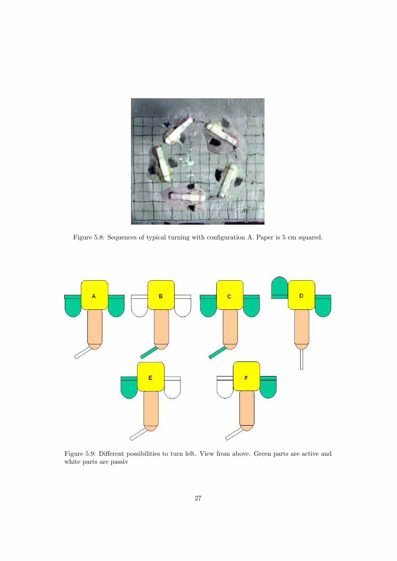
Figure 5.8: Sequences of typical turning with configuration A. Paper is 5 cm squared.
Figure 5.9: Different possibilities to turn left. View from above. Green parts are active andwhite parts are passiv
27
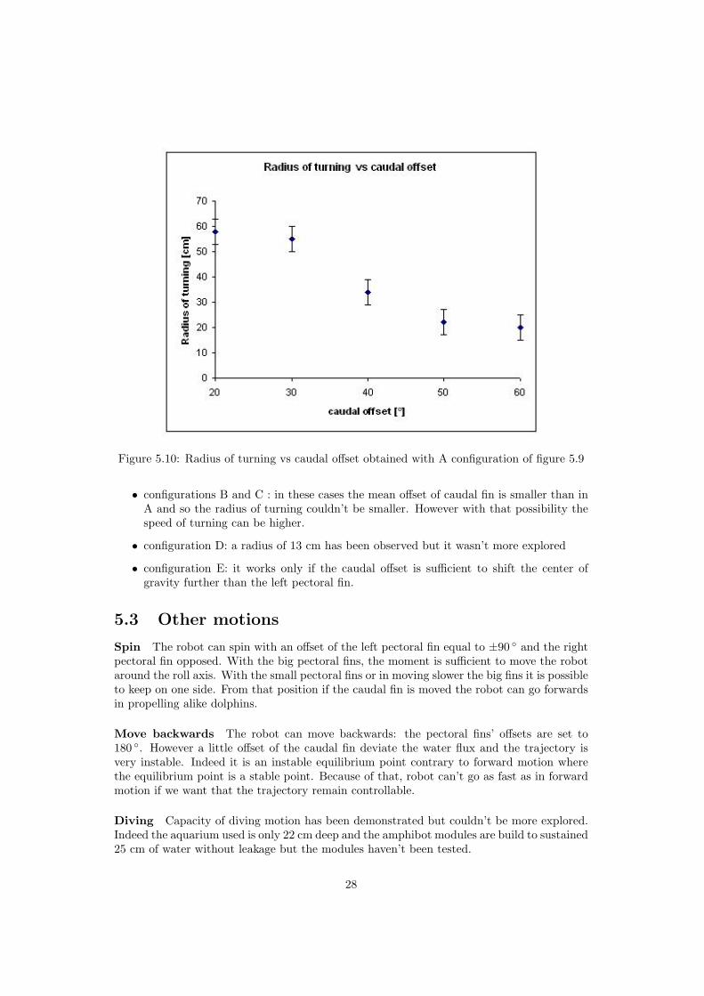
Figure 5.10: Radius of turning vs caudal offset obtained with A configuration of figure 5.9
• configurations B and C : in these cases the mean offset of caudal fin is smaller than inA and so the radius of turning couldn’t be smaller. However with that possibility thespeed of turning can be higher.
• configuration D: a radius of 13 cm has been observed but it wasn’t more explored
• configuration E: it works only if the caudal offset is sufficient to shift the center ofgravity further than the left pectoral fin.
5.3 Other motions
Spin The robot can spin with an offset of the left pectoral fin equal to ±90 ◦ and the rightpectoral fin opposed. With the big pectoral fins, the moment is sufficient to move the robotaround the roll axis. With the small pectoral fins or in moving slower the big fins it is possibleto keep on one side. From that position if the caudal fin is moved the robot can go forwardsin propelling alike dolphins.
Move backwards The robot can move backwards: the pectoral fins’ offsets are set to180 ◦. However a little offset of the caudal fin deviate the water flux and the trajectory isvery instable. Indeed it is an instable equilibrium point contrary to forward motion wherethe equilibrium point is a stable point. Because of that, robot can’t go as fast as in forwardmotion if we want that the trajectory remain controllable.
Diving Capacity of diving motion has been demonstrated but couldn’t be more explored.Indeed the aquarium used is only 22 cm deep and the amphibot modules are build to sustained25 cm of water without leakage but the modules haven’t been tested.
28

Figure 5.11: Different possibilities to dive. View from side. Green parts are active and whiteparts are passive
Walking If the pectoral fins are moved synchronously, the robot can go forward, draggingon the floor. Pectoral fins lift the robot and it fall further. However there is multipledrawbacks:
• works only with enough stiff fins (not with flexible fins)
• the friction coefficient has to be high: PE pectoral fins on smooth surface isn’t appro-priate
• at each step the robot fall, the chock could damage the robot
5.4 Trajectories’ follow
Except motor’s encoders, the robot has no sensors so it is impossible to follow a trajectory.However it is possible to chose a series of motion and to specify how long we want that therobot execute it. The motions are then executed in loop. An example of command is visiblein figure 5.12.
29
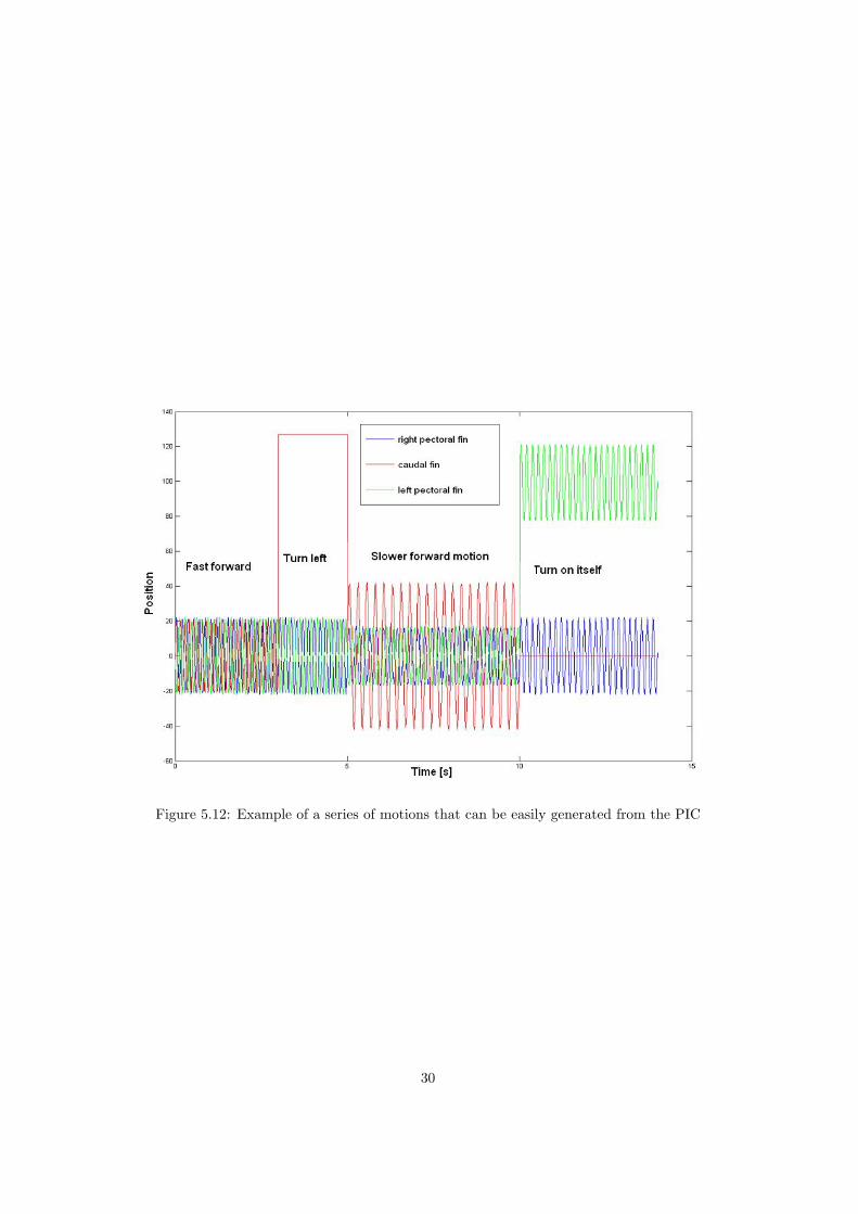
Figure 5.12: Example of a series of motions that can be easily generated from the PIC
30
Chapter 6
Future work
The next step is to add sensors, however it would be interesting to search for the betteraspect ratio of pectoral fins. A point that have to be improve is the method to program andrecharge batteries: opening the module very often cause a lot of mechanical problems andtake a lot of time.
The future possible works could be resume in the points below:
• Characterization of diving
• Characterization of fins for different aspect ratio
• Adding the possibility to get out cables for recharging batteries and program withoutopen the all module
• Adding of proprioceptive sensors : tilt sensor on roll axis
• Adding of exterioceptive sensors : light sensor
31
Chapter 7
Conclusion
The fish robot realized is 0.25 m long and can swim up to 0.37 m/s, the minimal radius ofturning observed is 0.13 m. The robot can dive, go forwards and backwards, swim on theside and do spins.
The speed is proportional to frequency and amplitude of the fins’ oscillations and is highlyproportional to the surface of the fins. Rubber fins provides smaller speed than PE fins andabove 2 Hz they aren’t appropriate for propulsion.
The caudal fin provide a bigger speed than the small pectoral fins but has a bigger surface.Use of the big pectoral fins provide the best performances. But like the development offishes in the nature, we have to adapt the robot to its environment: a smaller speed is muchappropriate in a confine space. So the use of the small pectoral fins could be better for testingmaneuvers in that aquarium in the future.
32

Appendix A
Mechanical drawings
33
Appendix B
Software
B.1 PIC’s program
34

B.2 Matlab
35

B.3 RS232 interface
36

Appendix C
Web sites of fish robots
These web sites were visited in march 2005.
• RoboTuna I, http://web.mit.edu/towtank/www/Tuna/Tuna1/tuna1.html
• RoboTuna II, http://web.mit.edu/towtank/www/Tuna/tuna.html
• RoboPike, http://web.mit.edu/towtank/www/Pike/pike.html
• SPC-II,http://www.vieartificielle.com/nouvelle/?id nouvelle=769
• Dongle,http://www.seattlerobotics.org/encoder /200211/autonomous robotic fish.html
• B1, http://www-personal.umich.edu/ bobden/biomechatronicdevices.html#Movie%20of%20our%20Biomechatronic%20Fish
• NMRI’s robots, http://www.nmri.go.jp/eng/khirata/fish/index e.html
• Essex University’s robots, http://privatewww.essex.ac.uk / jliua
• Coelacanth fish, http://www.mhi.co.jp/enews/e 0898.html
• Aqua project, http://www.aquarobot.net:8080/AQUA/AQUA/index html
37

Appendix D
Translation english-french offishes’ vocabulary
English FrenchTrout = truiteTuna = thonSalmon = saumonSwordfish = espadonMackerel = maquereauHerring = harengPike = brochetCarp = carpeCord = morueBoxfish = poisson coffreAngelfish = poisson angeeel = anguillelamprey = lamproiebuoyancy = flottabiliteair bladder = vessie natatoirefin = nageoirecaudal fin = nageoire caudalepectoral fins = nageoires pectoralespelvic fins = nageoires pelviennes ou ventralesmedian fins = nageoires impairesspiny rays = rayons pineuxsoft rays = rayons mous
38
Appendix E
Electronical parts
E.1 Control board Amphibot II - body module
39

E.2 Power board Amphibot II - body module
40

E.3 Power board Amphibot I - head module
41

E.4 Development board for PIC16f876A
42
Appendix F
motor control register summary[15]
43
Bibliography
[1] XINYAN DENG and SRINATH AVADHANULA Biomimetic Micro Un-derwater Vehicle with Oscillating Fin Propulsion: System Design andForce Measurement. Robotics and Intelligent Machines Laboratory Uni-versity of California, Berkeley, USA, 2005.
[2] DEAN H. THORSEN and MARK W. WESTNEAT Diversity of PectoralFin Structure and Function in Fishes With Labriform Propulsion. Depart-ment of Zoology, Division of Fishes, Field Museum of Natural History,Chicago, 2005.
[3] JUNZHI YU and LONG WANG Parameter Optimization of SimplifiedPropulsive Model for Biomimetic Robot Fish. Intelligent Control Labora-tory Center for Systems and Control, Department of Mechanics and Engi-neering Science Peking University, China, 2005.
[4] PABLO VALDIVIA Y ALVARADO and KAMA YOUCEF-TOUMI Per-formance of Machines with Flexible Bodies Designed for Biomimetic Lo-comotion in Liquid Environments.Mechanical Engineering Department,MIT, USA, 2005.
[5] EUNJUNG KIM and YOUNGIL YOUM Simulation Study of Fish Swim-ming Modes for Aquatic Robot System. Department of Mechanical Engi-neering, Pohang University of Science and Technology(POSTECH), Po-hang, Korea , 2005.
[6] NAOMI KATO ”Control Performance in the Horizontal Plane of a FishRobot with Mechanical Pectoral Fins”, Ieee journal of ocenaic engineering,vol. 25, no. 1, January 2000.
[7] JUNZHI YU, MIN TAN, SHUO WANG and ERKUI CHEN ”Developmentof a Biomimetic Robotic Fish and Its Control Algorithm”, Ieee transactionson systems, man, and cybernetics, Part B: cybernetics, vol. 34, no. 4,August 2004.
[8] JINDONG LIU, IAN DUKES, ROB KNIGHT, HUOSHENG HU Devel-opment of fish-like swimming behaviours for an autonomous robotic fish.Department of Computer Science, University of Essex, United Kingdom,2004.
[9] J.E. COLGATE, K.M. LYNCH ”Mechanics and Control of Swimming: AReview”, Ieee journal of oceanic engineering, vol. 24, no. 3, July 2004.
44
[10] MICHAEL SFAKIOTAKIS, DAVID M. LANE and J. BRUCE C. DAVIES”Review of Fish Swimming Modes for Aquatic Locomotion”, Ieee journalof ocenaic engineering, vol. 24, no. 2, April 1999.
[11] C.C. LINDSEY, Form, function and locomotory habits in fish Fish Phys-iology Vol. VII Locomotion, edited by W.S. Hoar and D.J. Randall. NewYork: Academic Press, 1978, pp. 1-100.
[12] Web site of Microchip Technology Inc. http://www.microchip.com
[13] A. WHEELER, Les poissons d’eau douce, Ed. Solar, 1983.
[14] B.-J MUSS, J.-G NIELSEN, P. DAHLSTROM et B. OLESEN NYSTROMGuide des poissons de mer et de peche, Ed. Delachaux et niestle, 1998.
[15] The ASL I2C motor control module, institut d’ingenierie de systemes, lab-oratoire de systemes autonomes 2, EPFL, 2003
45