BOX WING AIRCRAFT CONCEPTUAL DESIGN
10
BOX WING AIRCRAFT CONCEPTUAL DESIGN Paul O Jemitola * , John P Fielding * * Department of Aerospace Engineering, Cranfield University [email protected]; j.p.fielding@cranfield.ac.uk Keywords: keywords list (Box Wing, Joined Wing, Optimization, Tip Fin Inclination, Wing/Tip Fin Joint Fixity) Abstract This paper presents a conceptual design process for a medium range box wing aircraft is pre- sented. The process begins with the initial es- timates of components parameters followed by a constraint analysis to chose a design point. Struc- tural considerations such as the appropriate wing mass estimation methods for box wing, wing/tip fin joint fixities and tip fin inclination are then presented. An investigation of longitudinal sta- bility issues including trim and short period os- cillation are also presented before description of the optimization routine developed for the study. Finally, a comparison is presented of how the box wing compares with a conventional cantilever wing aircraft designed for the same mission and payload. Nomenclature A Aspect ratio AoA Angle of attack b Span C 1 Mass coefficient DOC Direct operating cost FD Fuselage diameter FEA Finite element analysis FL Fuselage length lbs Pounds LFL Landing field length m Million M TOM Maximum take-off mass nm Nautical mile pax Passenger TFL Takeoff field length S Wing area USD United States Dollars ∧ 1/4 Quarter chord sweep angle 1 Introduction As part of the search for the next future airliner configuration, and to mitigate the negative impact of airliners on the environment, there has been renewed interest in unconventional designs. An aircraft configuration of interest is the box/joined wing aircraft configuration, which in recent times has attracted the attention of researchers due to its claimed merits of reduced structural weight and low induced drag[1]. Box/joined wing aircraft potential of improved fuel efficiency and reduced direct operating costs have been other reasons to investigate the configuration. Box/joined wing aircraft have different names, such as box wing, biplane and diamond wing. The essential difference is in the wing con- figuration and the principle of operation; see Figs 1 and 2. This study is about the joined wing air- craft that has tip fins linking the tips of the fore and aft wings together and appropriately called a box wing aircraft. The box wing of this study is based on Prandtl’s[2] ‘best wing system’ where a closed rectangular lifting system produces the smallest possible induced drag for a given span and height. Frediani[3] posits that Prandtl’s[2] ‘best wing system’, if applied to current aircraft could offer induced drag reductions of up to 20- 1
Transcript of BOX WING AIRCRAFT CONCEPTUAL DESIGN

BOX WING AIRCRAFT CONCEPTUAL DESIGN
Paul O Jemitola∗, John P Fielding∗∗Department of Aerospace Engineering, Cranfield University
[email protected]; [email protected]
Keywords: keywords list (Box Wing, Joined Wing, Optimization, Tip Fin Inclination, Wing/Tip FinJoint Fixity)
Abstract
This paper presents a conceptual design processfor a medium range box wing aircraft is pre-sented. The process begins with the initial es-timates of components parameters followed by aconstraint analysis to chose a design point. Struc-tural considerations such as the appropriate wingmass estimation methods for box wing, wing/tipfin joint fixities and tip fin inclination are thenpresented. An investigation of longitudinal sta-bility issues including trim and short period os-cillation are also presented before description ofthe optimization routine developed for the study.Finally, a comparison is presented of how the boxwing compares with a conventional cantileverwing aircraft designed for the same mission andpayload.
Nomenclature
A Aspect ratioAoA Angle of attackb SpanC1 Mass coefficientDOC Direct operating costFD Fuselage diameterFEA Finite element analysisFL Fuselage lengthlbs PoundsLFL Landing field lengthm MillionMTOM Maximum take-off massnm Nautical milepax Passenger
TFL Takeoff field lengthS Wing areaUSD United States Dollars∧1/4 Quarter chord sweep angle
1 Introduction
As part of the search for the next future airlinerconfiguration, and to mitigate the negative impactof airliners on the environment, there has beenrenewed interest in unconventional designs. Anaircraft configuration of interest is the box/joinedwing aircraft configuration, which in recent timeshas attracted the attention of researchers due to itsclaimed merits of reduced structural weight andlow induced drag[1]. Box/joined wing aircraftpotential of improved fuel efficiency and reduceddirect operating costs have been other reasons toinvestigate the configuration.
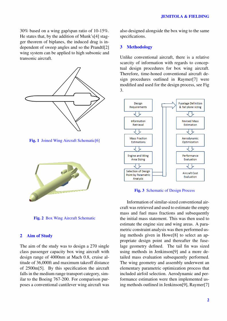
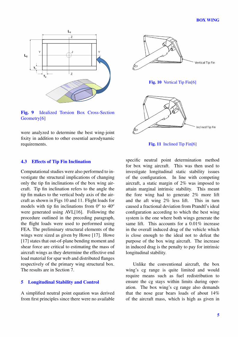
Box/joined wing aircraft have differentnames, such as box wing, biplane and diamondwing. The essential difference is in the wing con-figuration and the principle of operation; see Figs1 and 2. This study is about the joined wing air-craft that has tip fins linking the tips of the foreand aft wings together and appropriately called abox wing aircraft. The box wing of this study isbased on Prandtl’s[2] ‘best wing system’ wherea closed rectangular lifting system produces thesmallest possible induced drag for a given spanand height. Frediani[3] posits that Prandtl’s[2]‘best wing system’, if applied to current aircraftcould offer induced drag reductions of up to 20-
1
JEMITOLA & FIELDING
30% based on a wing gap/span ratio of 10-15%.He states that, by the addition of Munk’s[4] stag-ger theorem of biplanes, the induced drag is in-dependent of sweep angles and so the Prandtl[2]wing system can be applied to high subsonic andtransonic aircraft.
Fig. 1 Joined Wing Aircraft Schematic[6]
Fig. 2 Box Wing Aircraft Schematic
2 Aim of Study
The aim of the study was to design a 270 singleclass passenger capacity box wing aircraft withdesign range of 4000nm at Mach 0.8, cruise al-titude of 36,000ft and maximum takeoff distanceof 2500m[5]. By this specification the aircraftfalls in the medium range transport category, sim-ilar to the Boeing 767-200. For comparison pur-poses a conventional cantilever wing aircraft was
also designed alongside the box wing to the samespecifications.
3 Methodology
Unlike conventional aircraft, there is a relativescarcity of information with regards to concep-tual design procedures for box wing aircraft.Therefore, time-honed conventional aircraft de-sign procedures outlined in Raymer[7] weremodified and used for the design process, see Fig3.
Fig. 3 Schematic of Design Process
Information of similar-sized conventional air-craft was retrieved and used to estimate the emptymass and fuel mass fractions and subsequentlythe initial mass statement. This was then used toestimate the engine size and wing areas. A para-metric constraint analysis was then performed us-ing methods given in Howe[8] to select an ap-propriate design point and thereafter the fuse-lage geometry defined. The tail fin was sizedusing methods in Jenkinson[9] and a more de-tailed mass evaluation subsequently performed.The wing geometry and assembly underwent anelementary parametric optimization process thatincluded airfoil selection. Aerodynamic and per-formance estimation were then implemented us-ing methods outlined in Jenkinson[9], Raymer[7]
2

BOX WING
and Roskam[10]. Landing gear details were de-termined using Raymer[7] while position andloading were chosen consistent with Howe[8].Field performance was evaluated using methodsgiven in Raymer[7] and consistent with Ojha[11],Eshelby[12]. Cost issues were performed by tak-ing an average of the outcomes of the methods inRaymer[7], Roskam[13] and Burns[14].
4 Structural and Aerodynamic Considera-tions
4.1 Modification of Mass Formula
One of the challenges in the conceptual designof a box wing airliner is estimating the wingmass. Several empirical formulae exist for esti-mating the mass of conventional cantilever wingsbut these would be misleading if applied directlyto an unconventional configuration such as boxwing aircraft. Therefore, a procedure for defin-ing an empirical formula for the mass estimationof the fore and aft wings of a box wing aircraftshown in Fig 4, was performed.
Fig. 4 Procedure Schematic
Ten different box wing aircraft models withappropriate medium range wing parameters weregenerated. The wing parameters of the ten boxwing models were subsequently used to generatetwenty cantilever winged (ten forward swept andten aft swept but not joined at the tips) aircraftmodels. The masses of these wings were thenestimated using Howe’s[15] method. Howe’s[15]
method, Eqn 1, requires a coefficient, C1 whichdepends on the type of aircraft. Typical C1 valuesare shown in Table 1.
Table 1 Aircraft Type Mass Coefficients[15]Aircraft Type C1
Long Range 0.028Short Range 0.034Braced Wing 0.021Light aircraft 0.028 - 0.034
Next, to obtain the wing load distributionsfor an assumed flight condition each of thetwenty cantilever winged aircraft was modelledin a vortex lattice tool called Athena VortexLattice[16](AVL). AVL is a program that uti-lizes vortex-lattice theory for aerodynamic anddynamic stability analysis of a given aircraft ge-ometry. Fig 5 shows an AVL model of a box wingaircraft.
Fig. 5 Box Wing AVL Model
The wing loads were then used to performfinite element analysis (FEA) on the torsionbox models of the entire cantilever wingedaircraft from which the torsion box masses wereobtained. A relationship was subsequently es-tablished between the empirical and torsion boxmasses of the twenty cantilever wing aircraft.In a similar manner the ten box wing models(joined at the tip)were modelled in AVL to obtainthe wing loads and distribution for an assumedflight condition. The wing loads were then usedto perform FEA on the torsion box models of the
3

JEMITOLA & FIELDING
MW = C1
[bS
Cos∧1/4
(1+2λ
3+3λ
)(MTOMNS
)0.3(VD
τ
)0.5]0.9
(1)
box wing aircraft from which their masses wereobtained. A relationship was thereafter plottedwith the equivalent cantilever torsion box modelmass and that of the box wing. Using regressionanalysis the coefficients for the fore and aftwings were derived. By relating the torsion boxmasses of the box wing aircraft models to thatof the conventional aircraft wing models andextending this relationship to their empiricalmasses, wing mass estimation coefficients, C1in Howe[15], were derived for the fore and aftwings of the medium range box wing aircraft;see results in Section 7.
Fig. 6 Location of Joints
Fig. 7 Wing/Tip Fin Joint Fixities
4.2 Structural Consequences of Joint Fixity
A computational study was performed to com-pare the stress distributions in finite elementtorsion box models of a box wing structure thatresult from employing four different wing/tipfin joint fixities. The joint fixity types were theuniversal, ball, pin and rigid joints, see Figs 6and 7, and they refer to the type of attachmentthat connects the tip of the fore and aft wings tothe tip fin. The wing root to wing tip load distri-butions used for the analysis were obtained fromAVL[16]. Studies by Wolkovitch[1] indicate thatthe optimum wing torsion box cross-sectionalprofile of the box wing configuration is onewhich accounts for the tilted bending axis of thewings by having the ‘bending-resistant material’concentrated near the upper leading edges andlower trailing edges as illustrated in Fig 8.
Fig. 8 Box Wing Tilted Bending Axis
However, for simplicity, an idealized wingtorsion box cross-sectional geometry, sketchedin Fig 9, was used in the study. The loadsobtained from AVL were used to perform FEAof a statically loaded idealized box wing config-uration. Due to the simplicity of the torque boxand elastic axis beam type models used for thestress/strain analysis, only general stress trends
4
BOX WING
Fig. 9 Idealized Torsion Box Cross-SectionGeometry[6]
were analyzed to determine the best wing-jointfixity in addition to other essential aerodynamicrequirements.
4.3 Effects of Tip Fin Inclination
Computational studies were also performed to in-vestigate the structural implications of changingonly the tip fin inclinations of the box wing air-craft. Tip fin inclination refers to the angle thetip fin makes to the vertical body axis of the air-craft as shown in Figs 10 and 11. Flight loads formodels with tip fin inclinations from 0o to 40o
were generated using AVL[16]. Following theprocedure outlined in the preceding paragraph,the flight loads were used to performed usingFEA. The preliminary structural elements of thewings were sized as given by Howe [17]. Howe[17] states that out-of-plane bending moment andshear force are critical to estimating the mass ofaircraft wings as they determine the effective endload material for spar web and distributed flangesrespectively of the primary wing structural box.The results are in Section 7.
5 Longitudinal Stability and Control
A simplified neutral point equation was derivedfrom first principles since there were no available
Fig. 10 Vertical Tip Fin[6]
Fig. 11 Inclined Tip Fin[6]
specific neutral point determination methodfor box wing aircraft. This was then used toinvestigate longitudinal static stability issuesof the configuration. In line with competingaircraft, a static margin of 2% was imposed toattain marginal intrinsic stability. This meantthe fore wing had to generate 2% more liftand the aft wing 2% less lift. This in turncaused a fractional deviation from Prandtl’s idealconfiguration according to which the best wingsystem is the one where both wings generate thesame lift. This accounts for a 0.01% increasein the overall induced drag of the vehicle whichis close enough to the ideal not to defeat thepurpose of the box wing aircraft. The increasein induced drag is the penalty to pay for intrinsiclongitudinal stability.
Unlike the conventional aircraft, the boxwing’s cg range is quite limited and wouldrequire means such as fuel redistribution toensure the cg stays within limits during oper-ation. The box wing’s cg range also demandsthat the nose gear bears loads of about 14%of the aircraft mass, which is high as given in
5

JEMITOLA & FIELDING
Howe[8]. Howe[8] states that the nose shouldbear loads ranging from 6% to 15% at operatingempty mass (OEM) and maximum takeoff mass(MTOM) respectively. However, for the box wingthis load stays virtually constant throughout itslimited cg range and so may not be very critical.
Using inertia statements of the box wing andconventional aircraft, along with aerodynamicdata generated from Javafoil[18], trim analyseswere performed in J2[19] for both aircraft atcruise to investigate trim stability. Thereafter,longitudinal dynamic analyses was performed togive insight into the short period oscillation ofboth aircraft. The results were then inputted onthe longitudinal short period pilot opinion con-tours chart called the ‘thumb print’ criterion. The‘thumb print’ criterion provides guidance to air-craft designers and evaluators concerning the bestcombinations of longitudinal short period modedamping and frequency to give good handlingqualities. The chart is empirical and is based en-tirely on pilot opinion but adequate for concep-tual design studies. The results are shown in Sec-tion 7.
6 Optimization Method
A design/optimization tool was developed tooptimize the box wing and conventional can-tilever aircraft designs. The design tool wasimplemented in Microsoft Excel and enhancedby Visual Basic for Application (VBA) algo-rithms. The tool was setup to solve multiobjec-tive and multidisciplinary optimization problemsusing deterministic gradient search and stochas-tic non-gradient search algorithms. Furthermore,the results of the wing mass estimation coef-ficient, wing/tip fin joint fixity and tip fin in-clination studies were implemented in the de-sign/optimization tool. The architecture of thedesign tool is as shown in Fig 12 and it con-sists broadly of baseline design, geometry defi-nition, wing structures, mass, aerodynamics, per-formance and cost modules. The arrows showthe direction and paths of optimization routinesof the tool.
Fig. 12 Design Method Architecture
In the tool’s multidisciplinary design opti-mization setup the constraints were takeoff dis-tance, cruise speed and landing distance whilethe parameters were number of engines, fuselagediameter, aerofoils, wing span and wing gap forthe box wing. The design variables were wingsweep, wing area and average thickness to chordratio. The objective functions or measures ofmerit were minimization of all-up-mass, fuel perpax per nautical mile and DOC per nautical mile.
7 Results
The wing mass estimation coefficient of 0.28derived for the fore wing proved to be the sameas that derived for the aft wing. As the wingscarry the same load and are connected by tip finsit was anticipated that their coefficient may bethe same, because the wings are mutually bracingeach other and the same set of constraints wereapplied to both. The significance of this is thatthe aft wing of a medium range box wing aircraftwould be lighter than the fore wing. The reasonfor this is that for a medium range box wingaircraft the sweep angle of the aft wing wouldtypically be less than that of the fore wing (wingarea being the same), the resulting mass of theaft wing would thus be lower. This general resultis of significance to the conceptual designer, for
6

BOX WING
this difference in mass would be of considerationfor center of gravity and static margin issues ofthe configuration. The mass difference wouldalso be of influence in the positioning of otherheavy items such as engines and landing gears.
Of the 4 joint types investigated, the rigidjoint offered a lighter structure than any of theother three, with its significantly lower wing rootout-of-plane bending moment. The rigid jointdoes not accentuate aero elastic problems be-cause it transmits all stresses, it should also pro-duce a heavier tip fin meaning greater inertia re-lief. However, this increase in the moment of in-ertia has a consequence of reduced roll respon-siveness; an undesirable development for mili-tary aircraft but less critical for civil transports.The rigid joint also produces greater overall wingstiffness which could have ameliorating effectson the reduced roll responsiveness caused by aheavier tip fin. Finally, the rigid joint allows forthe design of the wing tip/tip fin junction to takefull advantage of the aerodynamic benefits of theconfiguration.
Fig. 13 Tip Fin Section[6]
Tip fin inclination significantly affects thetorsional force, dragwise shear force and drag-wise bending moment distributions in the wingsof a box wing aircraft. However, there are onlyminor variations in out-of-plane bending momentand shear force distributions as a function oftip fin inclination. Minor variations were alsoobserved in the cases for the tip fin torsion box
masses, the overall wing torsion box masses andwing tip deflections. The changes in torsionalforce, dragwise shear force and dragwise bend-ing moment with tip fin inclination did not affectthe structural design of the tip fin as they are notdesign driving parameters.
The changes in torsion and dragwise shearforce are not significant because the stiffnessof the section is high enough along the foreand aft planes not to provoke an appreciabledifference in deformation of the tip fin, seeFig 13. However, these torsion and dragwiseshear force distributions would have significantinfluences on the wing/tip fin joint design andsuggests heavy joints; an area not covered in thispaper.
Furthermore, the minor variation in theout-of-plane bending moment, shear force dis-tributions and torsion box masses suggests thattip fin inclination has a reduced effect on thestructural design of a box wing aircraft. Thisdeduction is valid from a structural viewpointbut tip fin inclination could have non negligibleeffects on the dynamic modes, flutter speed andfrequency; areas not investigated.
The box wing and conventional aircraft trimwere compared while cruising at 31,000ft atMach 0.8 trimmed. From Table 2 both aircraftwere cruising at about the same angle of attackbut while the conventional aircraft’s wing had apositive angle of attack the box wing’s fore winghad a negative angle of attack. At the tailplaneand aft wing both had positive angle of attack.
The fact that for the box wing aircraft the forewing is at a ‘low’ angle and the aft wing a ‘high’angle is in line with Bell’s[20] highlight thatthe rear wing induces an upwash on the forwardwing, which in turn induces a downwash on therear wing. Thus, the fore wing’s negative angleof attack is to compensate for the increased angleof attack caused by the upwash on it induced bythe aft wing. Similarly, the aft wing’s rather highangle of attack is to compensate for the reduced
7

JEMITOLA & FIELDING
Table 2 Aircraft Trim Parameters at Mach 0.831,000ftParameter (o) Conventional Box
AoA 1.70 1.68Wing AoA 2.94 -1.32Elevon 3.10Tailplane/Aft wing AoA 1.12 2.10Elevator -0.22 -5.13
angle of attack induced on it by the downwashfrom the fore wing.
The trim drag of the conventional aircraftwith an elevator angle of −0.22o would be muchlower than that of the box wing with elevonand elevator angles of 3.10o and −5.13o respec-tively. This suggests that further optimization isrequired for the box wing as the trim drag sug-gested by this simulation could reduce the advan-tage the box wing configuration has over the con-ventional aircraft.
Fig. 14 Thumb Print Criterion[21]
The box wing aircraft model and the con-ventional cantilever wing aircraft model on the‘thumb print’ criterion is shown in Fig 14. Thisillustrates the significant difference between theconventional and the box wing aircraft. Whereasthe conventional aircraft falls in the satisfactoryarea of the ‘thumb print’ the box wing aircraftis in the unacceptable area. This is due to the
principle of operation of the box wing and thefact that the static margin for the box wing at 2%makes for marginal longitudinal stability. Thus,to retain the aerodynamic advantages of thebox wing configuration stability augmentationdevices would be required; a technology whichis well matured in the aviation industry.
Table 3 Design OutcomesAircraft Type Conventional Box Wing
Dimensionsb (m) 47.00 37.6A - fore/aft 11.39 12.62/12.62S - fore/aft (m2) 194.00 112.00/112.00∧1/4 - fore/aft (o) 27 29/-24FL (m) 46.00 46.00FD (m) 5.60 5.60
MassesOEM (kg) 53250.00 57605.00Payload (kg) 31050.00 31050.00MTOM (kg) 114916.00 114240.00Max fuel (kg) 46630.00 37692.00Max pax 270 270
PerformanceLFL (m) 1783 1615TFL (m) 1640 1336Range (nm) 4000 4000Price (2007USD) 108.7m 121.9mFuel/pax/nm(lbs) 0.062 0.052DOC/nm 20.88 20.34DOC/nm/seat 0.077 0.075
The outcomes of the design/optimization ofboth aircraft types are shown in Table 3 and theirsketches are shown in Figs 15 and 16. The boxwing aircraft MTOM came out being about 95%of that of the conventional aircraft and showsbetter field performance. Also significant is theDOC/nautical mile in which the box wing is97% of that of the conventional aircraft. Thecost performance values could be even lower butfor the new programme difficulty factor inputtedinto the aircraft cost algorithm to account for thenovel box wing configuration. This, amongst
8

BOX WING
Fig. 15 Optimized Conventional Aircraft
Fig. 16 Optimized Box Wing Aircraft
others, accounts for the relatively high aircraftmarket price shown in Table 3. However, theDOC/nautical mile advantage of the box wing in-creases with increase in the fuel price.
Fig. 17 DOC/nm Trend with Fuel Price Increase
Fig 17 shows how the box wing aircraft’sDOC/nautical mile benefit improves from 97%of the conventional cantilever wing aircraft at2.5 USD per gallon to 90% at 10 USD pergallon. Thus, with the likelihood of fuel pricescontinuously increasing and the carbon taxalready introduced in Europe, the box wing hasa clear advantage over conventional designs.Furthermore, the reduced wing span of the boxwing makes it suitable for large long rangedesigns that would easily fit into the 80m boxat airports. Thus, the box wing aircraft has thepotential of being a viable replacement to theconventional cantilever aircraft.
8 Recommendations for Future Work
The analytic models used for this study were rel-atively simple, to reduce the data preparation andthe turn-around time of data processing. Also,the weights estimated obtained from the finite el-ement tool in this study were limited to the struc-tural torsion box of the wing; trailing and leadingedges, control surfaces and auxiliary componentweights were excluded. Thus, for more detailedanalysis further studies would be required whichshould include torsion box cross-sections that ac-count for the aforementioned omissions and thetilted bending axis of the box wing configuration.
A non-linear analysis is recommended for fu-ture work in identifying post buckling behaviourof the box wing aircraft wing system. It is alsorecommended that flutter and divergence analy-sis of the box wing configuration be performedfor a more complete investigation into the effectsof the joint fixity. It is further recommended thata separate investigation on the effects of differenttip fin inclinations be performed from a purelyaerodynamic perspective. A comprehensive CFDanalysis is also recommended.
Acknowledgments
The authors acknowledges the support of the De-partment of Aerospace Engineering, CranfieldUniversity and the Nigerian Air Force.
9

JEMITOLA & FIELDING
References
[1] Wolkovitch J. The joined wing: an overview,Journal of Aircraft, Vol. 23, March 1986, pp.161-178.
[2] Prandtl L. Induced drag of multiplanes, Technis-che Berichte, Vol. III, No. 7, 1924.
[3] Frediani A. The prandtlwing, Lecture series oninnovative configurations and advanced con-cepts for future civil aircraft ISBN 2-930389-62-1, Von Karman Institute, VKI 2005-06, 2005.
[4] Munk M. The minimum induced drag of airfoils,Report 121, NACA, March 1923.
[5] Smith H and Jemitola PO. A - 9 box wingmedium range airliner - project specification,Department of Aerospace Engineering, Cran-field University, Cranfield, 2009.
[6] Jemitola PO and Monterzino G and FieldingJ and Lawson C. Tip fin inclination effect onstructural design of a box wing aircraft, Pro-ceedings of the Institution of Mechanical Engi-neers, Part G: Journal of Aerospace Engineer-ing, DOI: 10.1177/0954410011426528, 5 Jan-uary 2012.
[7] Raymer D. Aircraft Design : A Conceptual Ap-proach., American Institute of Aeronautics andAstronautics, Virginia, USA, 2006.
[8] Howe D. Aircraft Conceptual Design Synthe-sis., Professional Engineering Publishing Lim-ited, London, 2000.
[9] Jenkinson L and Rhodes D and Simpkin P. CivilJet Aircraft Design., Arnold Publishers, UK,1999.
[10] Roskam J. Airplane Design: Part VI - Prelim-inary Calculation of Aerodynamic, Thrust andPower Characteristics., Roskam Aviation andEngineering Corporation, Kansas, USA, 1990.
[11] Ojha SK. Flight Performance of Aircraft.,American Institute of Aeronautics and Astro-nautics, Washington DC, USA, 1995.
[12] Eshelby ME. Aircraft Performance : Theoryand Practice., Arnold Publishers, UK, 2000.
[13] Roskam J. Airplane Design: Part VIII - Air-plane Cost Estimation., Roskam Aviation andEngineering Corporation, Kansas, USA, 1990.
[14] Burns JW. Aircraft cost estimation methodologyand value of a pound derivation for preliminarydesign development applications, 53rd Annual
Conference, No 2228, Society of Allied WeightEngineers, Inc, California, May 1994.
[15] Howe D. DAeT 9317 - Aircraft Mass Prediction,Department of Aerospace Engineering, Cran-field University, Cranfield, 2009.
[16] Drela M. and Youngren, H. Athena vor-tex lattice user manual, Version 3.26,http://web.mit.edu/drela/Public/web/avl/,2006.
[17] Howe D. Aircraft Loading and Structural Lay-out., Professional Engineering Publishing Lim-ited, London, 2004.
[18] Hepperle M. Javafoil, Ver-sion 2.20 - 01, http://web.mh-aerotools.de/airfoils/javafoil.htm, December2010.
[19] John J. J2Universal aircraft dynamics softwaresuite, J2 Aircraft Dynamics Ltd, 2010.
[20] Bell A and Fromm J and Lowery S and RiggsS and Sleeper B and Tamayo M and Todd Jand Usmanov O. Design and optimization ofa joined-wing aircraft, University of Colorado,Boulder, Colorado, USA, 2008.
[21] Cook M. Flight Dynamics Principles., ElsevierLtd, Oxford, UK, 2nd Edition, 2007.
8.1 Copyright Statement
The authors confirm that they, and/or their company ororganization, hold copyright on all of the original ma-terial included in this paper. The authors also confirmthat they have obtained permission, from the copy-right holder of any third party material included in thispaper, to publish it as part of their paper. The authorsconfirm that they give permission, or have obtainedpermission from the copyright holder of this paper, forthe publication and distribution of this paper as part ofthe ICAS2012 proceedings or as individual off-printsfrom the proceedings.
10