Bowflex®Bowflex®Bowflex ... - Nautilus,...
20
Bowflex® Bowflex® Bowflex® TreadClimber® readClimber® readClimber® TC5500 TC5500 TC5500 001-7320–040109B
Transcript of Bowflex®Bowflex®Bowflex ... - Nautilus,...

Bowflex®Bowflex®Bowflex® TTTreadClimber®readClimber®readClimber® TC5500TC5500TC5500
001-7320–040109B
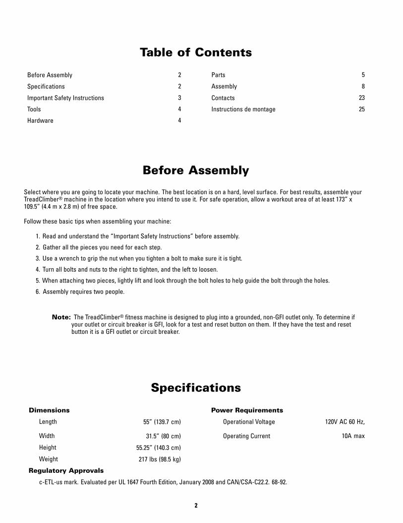
Table of Contents
Before Assembly 2 Parts 5
Specifications 2 Assembly 8
Important Safety Instructions 3 Contacts 23
Tools 4 Instructions de montage 25
Hardware 4
Before Assembly
Select where you are going to locate your machine. The best location is on a hard, level surface. For best results, assemble yourTreadClimber® machine in the location where you intend to use it. For safe operation, allow a workout area of at least 173” x109.5” (4.4 m x 2.8 m) of free space.
Follow these basic tips when assembling your machine:
1. Read and understand the “Important Safety Instructions” before assembly.
2. Gather all the pieces you need for each step.
3. Use a wrench to grip the nut when you tighten a bolt to make sure it is tight.
4. Turn all bolts and nuts to the right to tighten, and the left to loosen.
5. When attaching two pieces, lightly lift and look through the bolt holes to help guide the bolt through the holes.
6. Assembly requires two people.
Note: The TreadClimber® fitness machine is designed to plug into a grounded, non-GFI outlet only. To determine ifyour outlet or circuit breaker is GFI, look for a test and reset button on them. If they have the test and resetbutton it is a GFI outlet or circuit breaker.
Specifications
Dimensions Power Requirements
Length 55” (139.7 cm) Operational Voltage 120V AC 60 Hz,
Width 31.5” (80 cm) Operating Current 10A max
Height 55.25” (140.3 cm)
Weight 217 lbs (98.5 kg)
Regulatory Approvals
c-ETL-us mark. Evaluated per UL 1647 Fourth Edition, January 2008 and CAN/CSA-C22.2. 68-92.
222

Important Safety Instructions
This icon means a potentially hazardous situation which, if not avoided, could result in death or serious injury.
Obey the following warnings:
Read and understand all warnings on this machine.
Carefully read and understand the Assembly Manual.
••• Keep bystanders and children away from the product you are assembling at all times.
••• Do not connect power supply to the machine until instructed to do so.
••• Do not assemble this machine outdoors or in a wet or moist location.
••• Make sure assembly is done in an appropriate work space away from foot traffic and exposure to bystanders.
••• Some components of the machine can be heavy or awkward. Use a second person when doing the assembly steps involving
these parts. Do not do steps that involve heavy lifting or awkward movements on your own.
••• Set up this machine on a solid, level, horizontal surface.
••• Do not try to change the design or functionality of this machine. This could compromise the safety and can void the warranty.
••• If replacement parts are necessary use only genuine Nautilus® replacement parts and hardware. Failure to use genuine
replacement parts can cause a risk to users, keep the machine from operating correctly or void the warranty.
••• Do not use or put the machine into service until the machine has been fully assembled and inspected for correct performance
in accordance with the Owner’s Manual.
••• Read and understand the complete Owner’s Manual supplied with this machine before first use. Keep the Owner’s and
Assembly Manuals for future reference.
333

Tools
••• 13mm Open End Wrench or Adjustable Wrench (not included)
••• #2 Phillips Head Screwdriver (not included)
••• Utility Knife or Scissors (not included)
••• 5mm Hex Wrench (included)
Hardware
Item Qty Description
A 4 M8 x 20 Hex Head Bolt
B 16 M8 x 20 Button Head Hex Screw
C 20 M8 Spring Washer
D 4 M8 Wide Washer
E 16 M8 Regular Washer
F 4 Self Tapping Phillips Screw
G 1 5mm Hex Wrench
444

Parts
3 BOXES
BOX 1
Item Qty Description
1 1 Handle
2 2 Junction Cover
3 1 Console/Handlebar Assembly
4 1 Rear Cover
5 2 Cylinder
6 1 Manual Pack
7 1 Hardware Card
8 1 Power Cord
9 1 Motor Cover
555

Item Qty Description
10 1 Treadle Assembly
666
BOX 2

Item Qty Description
11 1 Base
12 1 Upright, Right
13 1 Upright, Left
777
BOX 3
Assembly
Step 1: Attach Handle to Base
NOTE: Hardware is pre-installed and not on Hardware Card.
888

Step 2: Attach Treadle Assembly to Base
999
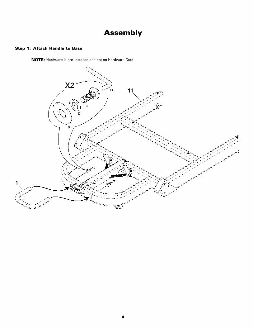
Step 3: Attach Motor Cover to Base Assembly
101010

Step 4: Secure Motor Cover to Base Assembly
111111

Step 5: Attach Junction Covers and Uprights to the Console/Handlebar Assembly
NOTE: Do not crimp the Console Cable.
121212

Step 6: Run the Console Cable through the Base Assembly
131313

Step 7: Attach the Console/Handlebar/Upright Assembly to Base Assembly
141414
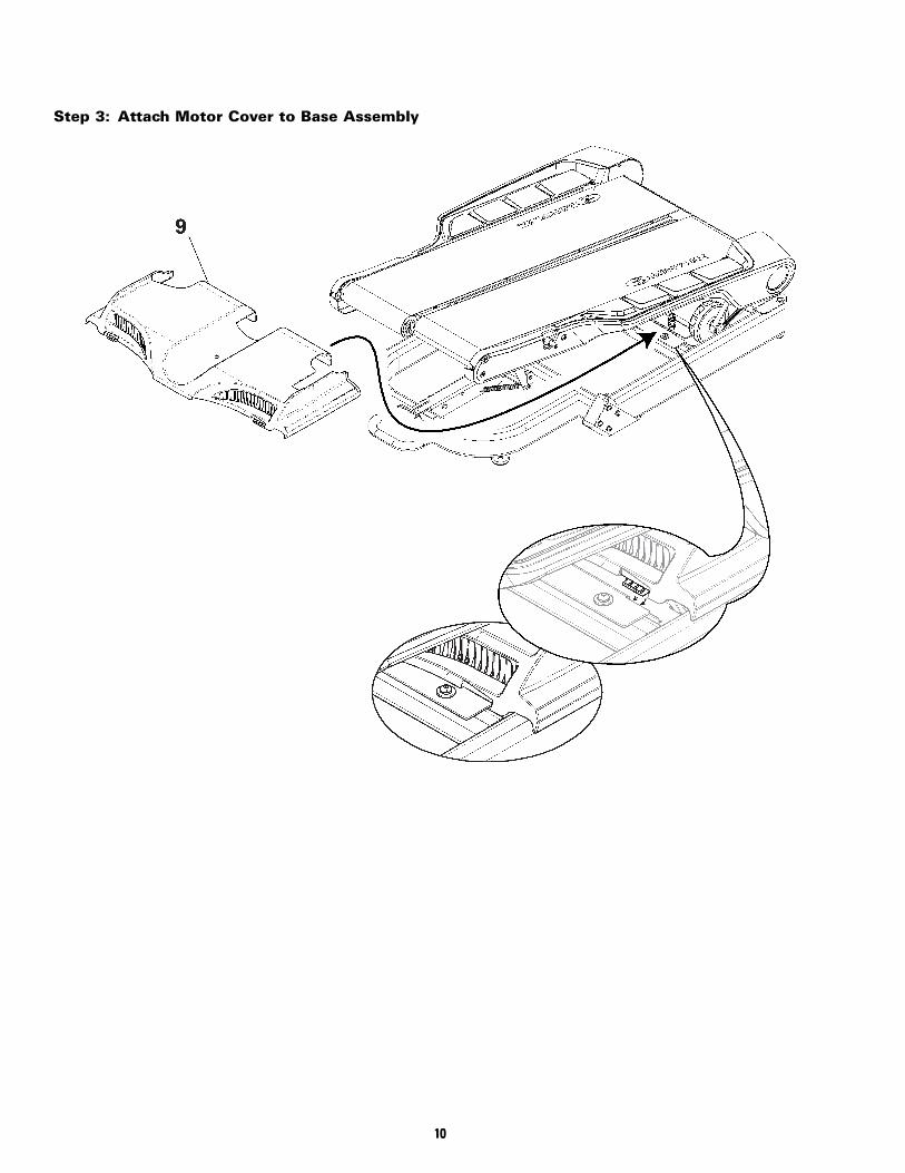
Step 8: Attach Cylinders to Uprights and then Treadle
NOTE: Hardware is pre-installed and not on Hardware Card.
The single, white arrow on top of the cylinders must point up and to the rear of the machine. Be sure toattach cylinder to upright before Treadle.
151515

Step 9: Connect the Console Cable to Rear of Machine
161616

Step 10: Attach Rear Cover
NOTE: Push the excess Console Cable inside the frame and then attach Rear Cover.
Be sure the safety tabs on the upper-inside of the Rear Cover snap onto the Base Assembly.
171717

Step 11: Connect Power Cord
Final Inspection
Inspect your machine to ensure that all fasteners are tight and components are properly assembled.
Do not use or put the machine into service until the machine has been fully assembled and inspected for correctperformance in accordance with the Owner’s Manual.
181818

Contacts
NORTH AMERICA
Customer ServiceTel: (800) 605–3369E-mail: [email protected]
CORPORATE HEADQUARTERSNautilus, Inc.World Headquarters16400 SE Nautilus DriveVancouver, WA, USA 98683Tel: (800) NAUTILUS (628-8458)
ASIA PACIFIC & LATIN AMERICA
Customer ServiceTel: (360) 859–5180Fax: (360) 859–5197E-mail: [email protected]
EUROPE, MIDDLE EAST & AFRICA
International Customer ServiceNautilus International GmbHAlbin-Köbis-Str. 451147 KölnTel: + 49 02203 2020 0Fax: + 49 02203 2020 45 45E-mail: [email protected]
GERMANY and AUSTRIANautilus International GmbHAlbin-Köbis-Str. 451147 KölnTel: + 49 02203 2020 0Fax: + 49 02203 2020 45 45
ITALYNautilus Italy S.r.l., Via della Mercanzia, 10340050 Funo di Argelateo - BolognaTel: + 39 051 664 6201Fax: + 39 051 664 7461
SWITZERLANDNautilus Switzerland SARue Jean Prouvé 6CH-1762 GivisiezTel: + 41 26 460 77 66Fax: + 41 26 460 77 60
UNITED KINGDOMNautilus UK Ltd4 Vincent AvenueCrownhill, Milton Keynes, Bucks, MK8 0ABTel: + 44 1908 267 345Fax: + 44 1908 267 345
191919

Printed in China
© 2009 Nautilus, Inc., All rights reserved
™ and ® indicate a trademark or registered trademark. Nautilus, Inc. (www.nautilus.com) trademarks include NAUTILUS®, BOWFLEX®, STAIRMASTER®, SCHWINN® and UNIVERSAL® and respective logos.
Other trademarks are the property of their respective owners.