
Boundary element analysis of three-dimensional cracks in ...
27
* Correspondence to: F. G. Yuan, Department of Mechanical and Aerospace Engineering, North Carolina State University, Raleigh, NC 27695, U.S.A. s E-mail: yuan@eos.ncsu.edu Contract/grant sponsor: National Science Foundation; contract/grant number: CMS-9713559 Contract/grant sponsor: Air Force O$ce of Scienti"c Research; contract/grant numbers: F33615-97-C-5089, F49620-98- 1-0104 Received 15 September 1998 Copyright ( 2000 John Wiley & Sons, Ltd. Revised 21 January 1999 INTERNATIONAL JOURNAL FOR NUMERICAL METHODS IN ENGINEERING Int. J. Numer. Meth. Engng. 2000; 48:211 } 237 Boundary element analysis of three-dimensional cracks in anisotropic solids Ernian Pan1 and F. G. Yuan2, *, s 1 Structures ¹ echnology, Inc., Cary, NC 27511, ;.S.A. 2 Department of Mechanical and Aerospace Engineering, North Carolina State ;niversity, Raleigh, NC 27695, ;.S.A. SUMMARY This paper presents a boundary element analysis of linear elastic fracture mechanics in three-dimensional cracks of anisotropic solids. The method is a single-domain based, thus it can model the solids with multiple interacting cracks or damage. In addition, the method can apply the fracture analysis in both bounded and unbounded anisotropic media and the stress intensity factors (SIFs) can be deduced directly from the boundary element solutions. The present boundary element formulation is based on a pair of boundary integral equations, namely, the displacement and traction boundary integral equations. While the former is collocated exclusively on the uncracked boundary, the latter is discretized only on one side of the crack surface. The displacement and/or traction are used as unknown variables on the uncracked boundary and the relative crack opening displacement (COD) (i.e. displacement discontinuity, or dislocation) is treated as a unknown quantity on the crack surface. This formulation possesses the advantages of both the traditional displacement boundary element method (BEM) and the displacement discontinuity (or dislocation) method, and thus eliminates the de"ciency associated with the BEMs in modelling fracture behaviour of the solids. Special crack-front elements are introduced to capture the crack-tip behaviour. Numerical examples of stress intensity factors (SIFs) calculation are given for transversely isotropic orthotropic and anisotropic solids. For a penny- shaped or a square-shaped crack located in the plane of isotropy, the SIFs obtained with the present formulation are in very good agreement with existing closed-form solutions and numerical results. For the crack not aligned with the plane of isotropy or in an anisotropic solid under remote pure tension, mixed mode fracture behavior occurs due to the material anisotropy and SIFs strongly depend on material anisotropy. Copyright ( 2000 John Wiley & Sons, Ltd. KEY WORDS : boundary element method; fracture mechanics; stress intensity factor; crack opening displace- ment; dislocations
Transcript of Boundary element analysis of three-dimensional cracks in ...
*Correspondence to: F. G. Yuan, Department of Mechanical and Aerospace Engineering, North Carolina StateUniversity, Raleigh, NC 27695, U.S.A.
sE-mail: [email protected]
Contract/grant sponsor: National Science Foundation; contract/grant number: CMS-9713559Contract/grant sponsor: Air Force O$ce of Scienti"c Research; contract/grant numbers: F33615-97-C-5089, F49620-98-1-0104
Received 15 September 1998Copyright ( 2000 John Wiley & Sons, Ltd. Revised 21 January 1999
INTERNATIONAL JOURNAL FOR NUMERICAL METHODS IN ENGINEERINGInt. J. Numer. Meth. Engng. 2000; 48:211}237
Boundary element analysis of three-dimensional cracksin anisotropic solids
Ernian Pan1 and F. G. Yuan2,*,s
1 Structures ¹echnology, Inc., Cary, NC 27511, ;.S.A.2 Department of Mechanical and Aerospace Engineering, North Carolina State ;niversity, Raleigh, NC 27695, ;.S.A.
SUMMARY
This paper presents a boundary element analysis of linear elastic fracture mechanics in three-dimensionalcracks of anisotropic solids. The method is a single-domain based, thus it can model the solids with multipleinteracting cracks or damage. In addition, the method can apply the fracture analysis in both bounded andunbounded anisotropic media and the stress intensity factors (SIFs) can be deduced directly from theboundary element solutions.
The present boundary element formulation is based on a pair of boundary integral equations, namely, thedisplacement and traction boundary integral equations. While the former is collocated exclusively on theuncracked boundary, the latter is discretized only on one side of the crack surface. The displacement and/ortraction are used as unknown variables on the uncracked boundary and the relative crack openingdisplacement (COD) (i.e. displacement discontinuity, or dislocation) is treated as a unknown quantity on thecrack surface. This formulation possesses the advantages of both the traditional displacement boundaryelement method (BEM) and the displacement discontinuity (or dislocation) method, and thus eliminates thede"ciency associated with the BEMs in modelling fracture behaviour of the solids. Special crack-frontelements are introduced to capture the crack-tip behaviour. Numerical examples of stress intensity factors(SIFs) calculation are given for transversely isotropic orthotropic and anisotropic solids. For a penny-shaped or a square-shaped crack located in the plane of isotropy, the SIFs obtained with the presentformulation are in very good agreement with existing closed-form solutions and numerical results. For thecrack not aligned with the plane of isotropy or in an anisotropic solid under remote pure tension, mixedmode fracture behavior occurs due to the material anisotropy and SIFs strongly depend on materialanisotropy. Copyright ( 2000 John Wiley & Sons, Ltd.
KEY WORDS: boundary element method; fracture mechanics; stress intensity factor; crack opening displace-ment; dislocations

INTRODUCTION
The boundary element method (BEM) is particularly attractive for linear elastic fracture mechan-ics [1, 2] in which SIFs and other fracture parameters play an important role in characterizingfracture behaviour of the solids. Accurate evaluation of singular state of stress near a crack tip haschallenged all the numerical modelling techniques. Especially for the conventional BEM, thegeometric coincidence of opposite nodes across the crack surfaces provides identical equations forthese nodal points. This yields a rank de"cient coe$cient matrix. To circumvent this di$culty,several methods within the scope of BEM have been suggested [3]. These include the specialGreen's function method [4] where the crack surface conditions are embedded into the Green'sfunction; the multi-domain technique [5] where each crack surface belongs to a distinct sub-region; the displacement discontinuity or dislocation method [6, 7]; and the Galerkin symmetricmethod [8].
Recently, several single-domain BEMs have been proposed for the study of cracked media [3].These single-domain BEMs involve two sets of boundary integral equations (one is the displace-ment integral equation, and the other is the traction type integral equation). One form of thesingle-domain BEMs is the so-called Dual Boundary Element Method (DBEM) where thedisplacement integral equation is collocated on the "nite uncracked boundary and on one sideof the crack surface, while the traction integral equation is collocated on the other side of thecrack surface. This DBEM has been developed for both two-dimensional [9] and three-dimen-sional [10] isotropic cracked media, and it has been applied to various fracture mechanicsproblems [2].
In the DBEM formulation, the displacements on each side of the crack surface are collocated asunknown variables, which may be unnecessary for the SIF calculation. Therefore, an idealsingle-domain BEM formulation would be the one, which requires discretization only on one sideof the crack surface. Applying the displacement integral equation to the uncracked boundaryonly, and the traction integral equation on one side of the crack surface can achieve suchsingle-domain BEM formulation. This single-domain BEM formulation has been proposed byPan and Amadei [11] and Pan [3] for two-dimensional anisotropic cracked solids. A similarformulation was proposed recently by Qin et al. [12] for three-dimensional isotropic crackedsolids in which the "nite-part integral involved was evaluated exactly. The advantages of usingthis new single-domain BEM formulation are two-fold: (i) the Cauchy-type singularity in thedisplacement integral equation can still be calculated directly by the rigid-body motion method;and (ii) for cracks in an in"nite domain, only the traction integral equation is needed to model theproblem [3]. The traction integral equation for in"nite domain problems resembles the displace-ment discontinuity or dislocation method, as has been investigated for some three-dimensionalfracture problems [13}20].
Although BEM has been widely applied to various fracture problems in three-dimensionalisotropic solids, relatively little attention has been paid to the three-dimensional anisotropic case[21] as to the authors' knowledge. A penny-shaped or elliptical crack in a linear elastic solid in anin"nite three-dimensional space under a far-"eld stress or uniform traction along the cracksurfaces, exact stress intensity factors for modes I, II, and III are available for either an isotropicsolid or a transversely isotropic solid with the plane of isotropy coincident with the plane of thecrack surface [22}24]. However, when the plane of isotropy is not aligned with the crack surface,the SIFs for an elliptical crack in an in"nite anisotropic solid can only be expressed by an integral[23]. If the material property, geometry and boundary conditions are symmetric with respect to
212 E. PAN AND F. G. YUAN
Copyright ( 2000 John Wiley & Sons, Ltd. Int. J. Numer. Meth. Engng. 2000; 48:211}237

the crack surface, the displacement integral equation can be employed to analyse some of therestricted 3-D crack problems in anisotropic media [25].
In this paper, we present a single-domain BEM formulation for linear elastic fracture mechan-ics analysis in three-dimensional anisotropic solids. This formulation is an extension of two-dimensional analysis [3] to the three-dimensional case and it is similar to Qin et al. [12] butextended to anisotropic solids. In this formulation, the displacement integral equation is collo-cated on the uncracked boundary and the traction integral equation on one side of the cracksurface. The Cauchy-type singularity involved in the displacement integral equation is calculateddirectly by the rigid-body motion method; the "nite-part integral associated with the tractionboundary integral equation is evaluated by Kutt's numerical quadrature [26, 27]. To illustratethe utility of the method, numerical examples are carried out for a penny-shaped and a square-shaped crack in transversely isotropic, orthotropic and anisotropic solids. The SIF values are ingood agreement with previously published results. Strong dependency of the SIFs on the materialanisotropy is demonstrated in the numerical examples.
BEM FORMULATION FOR THREE-DIMENSIONAL ANISOTROPICCRACKED SOLIDS
For a linearly elastic medium, we express the total displacements, stresses, and tractions throughlinear superposition as follows:
uti" u)
i#u1
i, p5
ij"p)
ij#p1
ij, ¹ 5
i"¹ )
i#¹ 1
i(1)
where the superscript t denotes the total solution, h the homogeneous solution, and p a particularsolution corresponding to the body forces and/or the far-"eld stresses. The advantage of using thelinear superposition (1) is the exact handling for the in"nite domain problem, as will soon becomeclear.
Following the procedure of Pan and Amadei [28] one can show that the total internaldisplacement solution at x
pcan be expressed by the following integral
u5i(xp)"!P
S
¹*ij(xp , xS)u5j
(xS) dS (xS)#P!¹*
ij(xp , x!`) [u5j
(x!`)!u5j(x!~ )]d! (x!`)
#PS
;*ij(xp , xS)¹5
j(xS) dS (xS)#P
S
¹*ij(xp , xS) [u1
j(xS)!u1
i(xp)] dS (xS)
!PS
;*ij(xp , xS)¹1
j(xS) dS (xS) (2)
where;*ij
and ¹*ij
represent the Green's functions for displacements and tractions which are givenexactly for a transversely isotropic solid with arbitrarily oriented isotropic plane (see AppendixA), and are given explicitly for a generally anisotropic solid (see Appendix B); summation from1 to 3 is implied on the repeated index; S and ! (&!
i) are the uncracked boundary of the body and
the crack surfaces, respectively, with the corresponding points being distinguished by subscriptS and ! (Figure 1); and a point on the positive (or negative) side of the crack is denoted by x!` (or
BOUNDARY ELEMENT ANALYSIS OF THREE-DIMENSIONAL CRACKS 213
Copyright ( 2000 John Wiley & Sons, Ltd. Int. J. Numer. Meth. Engng. 2000; 48:211}237
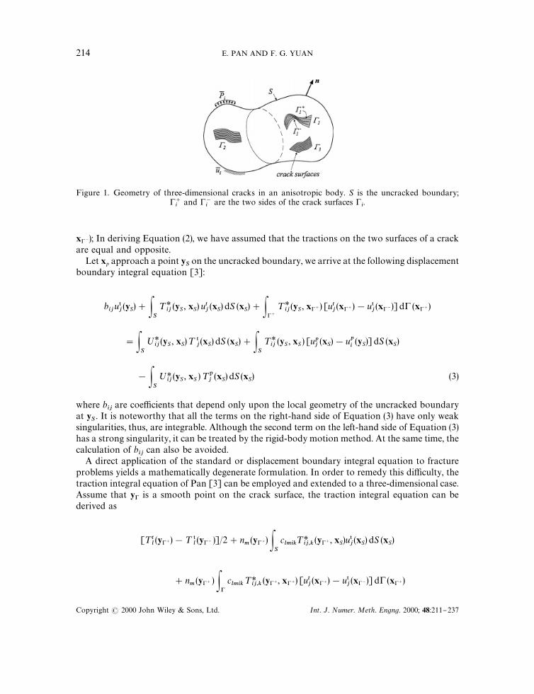
Figure 1. Geometry of three-dimensional cracks in an anisotropic body. S is the uncracked boundary;!`i
and !~i
are the two sides of the crack surfaces !i.
x!~); In deriving Equation (2), we have assumed that the tractions on the two surfaces of a crackare equal and opposite.
Let xp approach a point ySon the uncracked boundary, we arrive at the following displacement
boundary integral equation [3]:
biju5j(yS)#P
S
¹*ij(yS , xS) utj
(xS) dS (xS)#P!`
¹*ij(yS , x!`) [utj
(x!`)!u5j(x!~)] d! (x!`)
"PS
;*ij(yS , xS)¹ 5
j(xS) dS (xS)#P
S
¹*ij
(yS , xS ) [upj(xS)!up
i(yS)] dS (xS)
!PS
;*ij(yS , xS )¹1
j(xS) dS (xS) (3)
where bij
are coe$cients that depend only upon the local geometry of the uncracked boundaryat y
S. It is noteworthy that all the terms on the right-hand side of Equation (3) have only weak
singularities, thus, are integrable. Although the second term on the left-hand side of Equation (3)has a strong singularity, it can be treated by the rigid-body motion method. At the same time, thecalculation of b
ijcan also be avoided.
A direct application of the standard or displacement boundary integral equation to fractureproblems yields a mathematically degenerate formulation. In order to remedy this di$culty, thetraction integral equation of Pan [3] can be employed and extended to a three-dimensional case.Assume that y! is a smooth point on the crack surface, the traction integral equation can bederived as
[¹tl(y!`)!¹ 5
l(y!~ )]/2#n
m(y!`) P
S
clmik
¹*ij,k
(y!`, xS)u5j(xS) dS (xS)
#nm(y!` ) P!
clmik
¹*ij,k
(y!`, x!`) [utj(x!`)!u5
j(x!~)] d! (x!`)
214 E. PAN AND F. G. YUAN
Copyright ( 2000 John Wiley & Sons, Ltd. Int. J. Numer. Meth. Engng. 2000; 48:211}237
"[¹1l(y!`)!¹1
l(y!~)]/2#n
m(y!`) P
S
clmik;*
ij,k(y!`, xS)¹ 5
j(xS) dS (xS)
#nm(y!` ) P
S
clmik
¹*ij,k
(y!`, xS)u1j(xS) dS (xS)
!nm(y!
`) P
S
clmik;*
ij,k(y!`, xS)¹ 1
j(xS) dS (xS) (4)
where nm
is the unit outward normal of the positive side of the crack surface at y!` and clmik
is thefourth-order sti!ness tensor of the anisotropic medium; ;*
ij,kand ¹*
ij,kare the derivatives of the
Green's functions for displacements and tractions with respect to the source point respectively.Again these Green's functions are given exactly for a transversely isotropic solid with anyoriented isotropic plane (see Appendix A) and explicitly for a generally anisotropic solid (seeAppendix B).
Equations (3) and (4) form a pair of boundary integral equations and are similar to the single-domain BEMs of Mi and Aliabadi [10] for an isotropic medium. In this paper, however, thedisplacement integral equation is collocated exclusively on the uncracked boundary and thetraction integral equation on one side of the crack surface only. Furthermore, this formulationcan be applied to generally anisotropic media with the Cauchy-type integral being evaluatedexactly by the rigid-body motion method. It is also worth mentioning that the e!ect of the bodyforce and/or far-"eld stresses have been included by superposing the corresponding particularsolution, which makes the problem very similar to the one associated with the homogeneousgoverning equations. The only di!erence is that for the body force and/or far-"eld stress cases,two extra integral terms related to the particular solution need to be added to the homogeneousintegral equations. The advantage of using Equations (3) and (4) is that for the far-"eld stress case,the arti"cial truncation of the in"nite domain or transferring of the far-"eld stress onto theproblem boundary can be avoided. While the former method increases the size of the problemand also introduces errors because of the truncation of the region, the latter may not be suitablefor the cases where the boundary has a complex shape. In the following analysis, the superscript tassociated with the physical quantities will be omitted for simplicity, with the understanding thatthe physical quantities are the total ones.
For problems containing crack surfaces only, i.e. cracks in an in"nite space, only Equation (4)is required with the uncracked boundary integral terms being omitted. The resulting equationresembles the displacement discontinuity method [6] and the dislocation method [14, 19, 20, 29].For problems in an uncracked domain, only Equation (3) is required with the crack surfaceintegral terms being omitted. Equation (3) is then reduced to the traditional displacementboundary integral equation [30].
The boundary integral equations (3) and (4) can be discretized and solved numerically for theunknown boundary displacements (or displacement discontinuities on the crack surface) andtractions. It is emphasized that in deriving Equation (4), we have assumed a smooth crack surface.If the crack surface possesses discontinuous tangential planes at certain points or along certainlines, discontinuous elements are required in which the collocation points are moved away fromthese points or lines. The hypersingular integral term in Equation (4) also requires special
BOUNDARY ELEMENT ANALYSIS OF THREE-DIMENSIONAL CRACKS 215
Copyright ( 2000 John Wiley & Sons, Ltd. Int. J. Numer. Meth. Engng. 2000; 48:211}237

Figure 2. Four element types for the uncracked boundary.
attention and its handling by Kutt's [26, 27] numerical quadrature formulae will be discussed ina later section.
NUMERICAL SCHEME
Nine-node quadrilateral curved elements are employed to discretize both the uncracked bound-aries and crack surfaces. On each element, the displacement and/or traction on the uncrackedboundary, and the relative crack opening displacement (COD) on the crack surfaces can beapproximated by their nodal values. For example, the total displacement on each element can beexpressed as
ui"
9+k/1
/kuki, ¹
i"
9+k/1
/k¹ k
i, *u
i"
9+k/1
/k*uk
i, i"1, 2, 3 (5)
where /k
(k"1}9) are the shape functions, uki, ¹ k
i, and *ul
iare the nodal displacements, nodal
tractions, and nodal crack opening displacements at nodal point k and l, respectively.In order to handle the possible discontinuities of the geometric and boundary conditions of the
uncracked boundary and the crack surface, four and "ve types of nine-node quadrilateralelements are introduced respectively (Figures 2 and 3). It is noted that while element type I iscontinuous, others are discontinuous elements. The four sets of shape functions for the uncracked
216 E. PAN AND F. G. YUAN
Copyright ( 2000 John Wiley & Sons, Ltd. Int. J. Numer. Meth. Engng. 2000; 48:211}237

Figure 3. Five element types for the crack surface.
boundary are listed in Appendix C where the discontinuous nodes are at a distance of 1/3 fromthe element edge. Assuming isoparametric elements, the coordinates at any point in one elementare then related to its element nodal co-ordinates as follows:
x"9+k/1
/kxk1, y"
9+k/1
/kxk2, z"
9+k/1
/kxk3
(6)
Furthermore, in order to capture the speci"c characteristics of the COD near a crack front, weconstructed four sets of crack-front shape functions corresponding to the element type II}Vshown in Figure 3. For crack-front element types II}IV, the following shape functions areintroduced to approximate the COD
*ui"
9+k/1
(1#g)d`1uk*uk
i(7)
where d is the order of the stress singularity near the crack front [31]; *u*["u
i(x!`)!u
i(x!~)]
are the CODs, uk(k"1}9) are the nine shape functions which are similar to the corresponding
shape functions for the uncracked boundary, except for the di!erent coe$cients for each shapefunction, and *uk
iare the CODs at nodal point k.
BOUNDARY ELEMENT ANALYSIS OF THREE-DIMENSIONAL CRACKS 217
Copyright ( 2000 John Wiley & Sons, Ltd. Int. J. Numer. Meth. Engng. 2000; 48:211}237
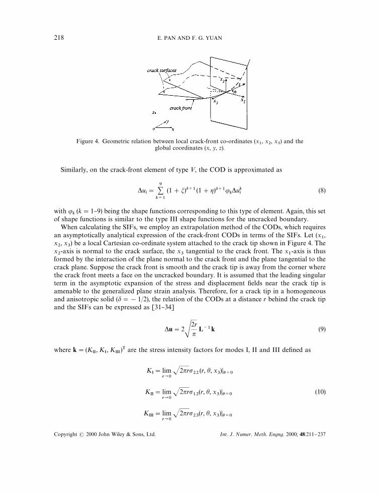
Figure 4. Geometric relation between local crack-front co-ordinates (x1, x
2, x
3) and the
global coordinates (x, y, z).
Similarly, on the crack-front element of type <, the COD is approximated as
*ui"
9+k/1
(1#m)d`1 (1#g)d`1uk*uk
i(8)
with uk(k"1}9) being the shape functions corresponding to this type of element. Again, this set
of shape functions is similar to the type III shape functions for the uncracked boundary.When calculating the SIFs, we employ an extrapolation method of the CODs, which requires
an asymptotically analytical expression of the crack-front CODs in terms of the SIFs. Let (x1,
x2, x
3) be a local Cartesian co-ordinate system attached to the crack tip shown in Figure 4. The
x2-axis is normal to the crack surface, the x
3tangential to the crack front. The x
1-axis is thus
formed by the interaction of the plane normal to the crack front and the plane tangential to thecrack plane. Suppose the crack front is smooth and the crack tip is away from the corner wherethe crack front meets a face on the uncracked boundary. It is assumed that the leading singularterm in the asymptotic expansion of the stress and displacement "elds near the crack tip isamenable to the generalized plane strain analysis. Therefore, for a crack tip in a homogeneousand anisotropic solid (d"!1/2), the relation of the CODs at a distance r behind the crack tipand the SIFs can be expressed as [31}34]
*u"2S2r
nL~1k (9)
where k"(KII, K
I, K
III)T are the stress intensity factors for modes I, II and III de"ned as
KI"lim
r?0J2nrp
22(r, h, x
3)Dh/0
KII"lim
r?0J2nrp
12(r, h, x
3)Dh/0
(10)
KIII"lim
r?0J2nrp
23(r, h, x
3)Dh/0
218 E. PAN AND F. G. YUAN
Copyright ( 2000 John Wiley & Sons, Ltd. Int. J. Numer. Meth. Engng. 2000; 48:211}237

Expression (9) is based on Stroh formalism. L is one of the Barnett}Lothe tensors which dependsonly on the anisotropic properties of the solid in the local crack-front co-ordinates, and*u"[*u
1, *u
2, *u
3]T is the COD in the local crack-front co-ordinates. On the crack-front
element, equating the CODs from the numerical calculation (7) or (8) to the analytical expression(9), one then obtains a set of algebraic equations from which the SIFs, K
I, K
II, and K
III, can be
solved.
TREATMENT OF HYPERSINGULAR INTEGRAL EQUATIONS
In solving the pairs of boundary integral Equations (3) and (4), special attention needs to be paidto the singular terms involved. As mentioned earlier, the Cauchy-type singularity in Equation (3)can be directly evaluated by the rigid-body motion method. For the "nite-part integrals inEquation (4), a Kutt's [26, 27] numerical quadrature is proposed to solve the hypersingularintegral equations.
On each isoparametric element, the "nite-part integral can be expressed as
P1
~1P
1
~1
F[y(m# , g# ), x (m, g)]/k(m, g)g (m, g)J (m, g) dm dg (11)
with
g (m,g)"G1 for interior elements
(1#g)d`1 for crack-front element types II}IV
(1#m)d`1(1#g)d`1 for crack-front element type V
(12)
Also in Equation (11), FJO (1/r3) represents one component of nmclmik
¹*ij,k
uj, /
kare the shape
functions and J is the Jacobian transformation. The collocation point x(mc, gc) in Equation (11)coincides with one of the nodal points on the element.
Introducing the following polar coordinates transform
m"m##r cosh(13)
g"g##r sin h
Equation (11) can then be rewritten as
+mP
h2
h1P
R (h)
0
F[y(m#, g#), x (r, h)]/k(r, h) g (r, h)J (r, h) rdr dh (14)
where the summation on m is for all the triangles needed on the element. For instance, if thecollocation point is one of the corner points of the element, the element is then divided into twotriangles, and the summation on m is from 1 to 2. On the other hand, if the collocation point is aninternal point, the element needs to be divided into four triangles. Consequently, the summationon m in Equation (14) is from 1 to 4. It is observed now that the integrand is O(1/r2). Therefore,
BOUNDARY ELEMENT ANALYSIS OF THREE-DIMENSIONAL CRACKS 219
Copyright ( 2000 John Wiley & Sons, Ltd. Int. J. Numer. Meth. Engng. 2000; 48:211}237

Kutt's [26, 27] numerical quadrature can be utilized to evaluate the inner "nite-part integral withrespect to r. The outer integral with respect to h is regular and can be calculated by the regularGauss quadrature.
For a given Gauss point hj, the inner integral in Equation (14) can be approximated by Kutt's
N-point equispace quadrature as
PR
0
f (r)
r2dr+
1
R
N+i/1
(wi#c
ilnR) f A
i!1
NRB (15)
where wiare the weights and c
ithe coe$cients given by Kutt, and the integrand is given by
f (r)"F[y(m#, g# ), x (r, hj)]/
k(r, h
j) g (r, h
j) J (r, h
j) r3 (16)
In applying Kutt's N-point equispace quadrature (15), it has been assumed that the integrandf (r)3C0[0, R] and f (r)3C2 in the neighbourhood of r"0 [26, 27]. Therefore, if the crack surfaceis #at, continuous elements can be used to discretize the interior crack surface, with discontinuouselements for the crack-fronts only. However, if the crack surface is curved, then discontinuouselements are needed for the whole crack surface in order to satisfy the continuity requirement forf (r). In the following numerical examples, Kutt's 20-point equispace quadrature is used to the"nite-part integral with respect to r, and 20 Guassian points for the regular outer integral withrespect to h. Since we restrict ourselves in this paper to the #at crack surfaces only, continuouselements are used to discretize the interior crack surface.
NUMERICAL RESULTS AND DISCUSSION
The Green's functions for transversely isotropic solids with arbitrarily oriented isotropic plane[28, 35] and for generally anisotropic solids [36] have been incorporated into the displacementand traction integral equations, and the resulting formulation has been programmed for numer-ical calculation. In this section, several numerical examples including the solids with in"nitedomain and "nite geometry are presented to verify the program and to show the e$ciency andaccuracy of the present BEM formulation in calculating the SIFs in transversely isotropic andanisotropic media. In all the examples, a uniaxial normal stress is applied normal to the cracksurface. The e!ects of material anisotropy, material orientation, crack geometry and "nitegeometry on the SIFs are demonstrated. Numerical results also show that material anisotropycan have a profound e!ect on the SIFs.
Example 1: A penny-shaped crack in an in,nite space
The "rst example considers a penny-shaped crack (with radius a"5 in.) located in the x}y planein an in"nite space under a far-"eld uniform stress p= applied in the z-direction. Forty-eightnine-node quadrilateral elements are used to discretize the crack surface (Figure 5). Geometricnodes and collocation points are also shown in the "gure. For the isotropic solid (E"4 Msi and
l"0.25 are used in modelling), the normalized mode-I stress intensity factor, KI/(2p=Ja/n),
along the crack front varies from 0.99 to 1.01, compared with the value of unity in the analytical
220 E. PAN AND F. G. YUAN
Copyright ( 2000 John Wiley & Sons, Ltd. Int. J. Numer. Meth. Engng. 2000; 48:211}237

Figure 5. Discretization of a penny-shaped crack (radius a"5 in.) with 48 nine-nodequadrilateral elements.
solution K3%&I"2p=Ja/n [37]. The largest deviation for the SIFs using the 3D BEM formulation
is only about 1 per cent, even with only 48 elements modelled in the crack region (16 elementsalong the crack front). It is noted that for the penny-shaped or elliptical crack, [37] the mode-ISIF in an in"nite isotropic solid is independent of the material property.
Two classes of transversely isotropic (TI) solids are then selected to study the e!ect of materialanisotropy on the SIFs.
For class I material, EX/E
Z"3, l
XY"0.25, l
YZ"0.25 and G
YZ/E
Z"0.4
For class II material, EX/E
Z"0.5, l
XY"0, l
YZ"0.4 and G
YZ/E
Z"0.8
The material properties for classes I and II are chosen from the papers by Pan and Amadei, [11]and Hoenig, [23] respectively. X, > and Z refer to longitudinal, transverse and normal directionrespectively. (X, >, Z) are often called principal material axes and the plane X}> is termed asprincipal material plane of the plane of isotropy in this case. In the transversely isotropic solids,EX"E
Y, G
XZ"G
YZ, l
XZ"l
YZ, and G
XY"E
X/2(1#l
XY). l
XYis the Poisson's ratio for trans-
verse strain in the >-direction when stressed in the X-direction (Figure 6).For the plane of isotropy parallel to the penny-shaped crack surface (x}y plane), TI-0, the 3-D
BEM results also predict a nearly constant SIF close to the analytical solution, K3%&I"2p=Ja/n,
along the crack front (Figure 7). However, for the plane of isotropy not parallel to the cracksurface, TI-90, the SIFs then vary along the crack front. In the case of the orientation angleb"903 and inclination angle t"903 (Figure 6), which corresponds to the plane of isotropybeing normal to the crack plane (or parallel to the space "xed x}z plane), the crack is under puremode-I subjected to a remote uniform stress p= in the z-direction. The variation of K
Ialong the
crack front is also shown in Figure 7 for the two classes of transversely isotropic solids. It isinteresting to note from Figure 7 that the variation of the SIF for class II is similar (but not the
BOUNDARY ELEMENT ANALYSIS OF THREE-DIMENSIONAL CRACKS 221
Copyright ( 2000 John Wiley & Sons, Ltd. Int. J. Numer. Meth. Engng. 2000; 48:211}237

Figure 6. Relationship between the principal material co-ordinates (X, >, Z) and the space-"xed globalcoordinates (x, y, z). b and t are the orientation and inclined angles, respectively. (X, >) is the principal
material plane or plane of isotropy.
same!) to that obtained by Hoenig [23]; variation of the SIF for classes I and II material followsa function
Ai#B
icos 2h, i"I or II (17)
where h is measured counterclockwise from the x-axis. Due to the di!erent material anisotropyratio, E
X/E
Z, between these two materials, the maximum (minimum) values of K
Ifor class I occur
at h"90 and 2703 (0 and 1803) respectively; reverse trend for class II.
Example 2: A square-shaped crack in an in,nite space
A square-shaped crack in the x}y plane in an in"nite space is studied in this example. The sidelength of the square is 2a ("6 in.), and a far-"eld stress p= is applied in the z-direction. Thesquare-shaped crack can be seen in Figure 13 which will be discussed in the next example. Onehundred (10]10) nine-node quadrilateral elements are used to discretize the square withthe meshes shown in Figure 8. To gain an insight into the stress intensity factors a!ected by thematerial anisotropy, two sets of material properties, transversely isotropic and anisotropicmaterials, are studied for this shape of the crack. The "rst set of numerical results utilizesa transversely isotropic (TI) material whose material properties are the same as the class I inExample 1. Three material orientations for the transversely isotropic material under normalloading are studied: (i) TI-0 corresponds to the plane of isotropy parallel to the crack surface;(ii) TI-90 represents the plane of isotropy normal to the crack surface (b"903 and t"900),respectively; and (iii) TI-45 corresponds to b"453 and t"453 where the sti!ness matrix is fully
populated. The normalized SIFs, KI/(p=Jna), along x"$a and y"$a for three material
orientations are shown in Figure 9.The variation of mode-I SIFs along the crack front for TI-0 either along x"$a or y"$a is
shown in Figure 9. For comparison, the SIFs for isotropic materials are also calculated andshown in the "gure. Note that for either a penny-shaped or an elliptical crack with crack planeparallel to the plane of isotropy in an in"nite space, the analytical forms for the mode-I stressintensity factor [22, 23] are independent of material properties. In this case of a square-shapedcrack in an in"nite space, the variation of mode-I SIFs along the crack front for the TI-0 shown in
222 E. PAN AND F. G. YUAN
Copyright ( 2000 John Wiley & Sons, Ltd. Int. J. Numer. Meth. Engng. 2000; 48:211}237

Figure 7. Variation of KI/(2p=Ja/n) along the penny-shaped crack front of transversely isotropic solids
(TI-0 and TI-90) in an in"nite space under a far-"eld normal stress p=.
Figure 8. Discretization of a square-shaped crack (side length 2a"6 in.) with 100 nine-nodequadrilateral elements.
Figure 9, as expected, is the same as that for the isotropic case, i.e. independent of materialproperties. The values are almost the same as that obtained by Weaver using a dislocationmethod. The maximum value occurs at the middle of the square side and decrease to zero at thecorners (x"$a, y"$a). The maximum SIF value that predicted from the 3-D BEM is 0.7626,as compared with 0.74 in Weaver [38] and 0.76 in Murakami [39] for isotropic solids.
The e!ect of material anisotropy on mode-I SIFs can be demonstrated in the TI-90 case. In thiscase, the mode-I SIF along the crack front y"$a is much larger than that along x"$a, about
BOUNDARY ELEMENT ANALYSIS OF THREE-DIMENSIONAL CRACKS 223
Copyright ( 2000 John Wiley & Sons, Ltd. Int. J. Numer. Meth. Engng. 2000; 48:211}237

Figure 9. Variation of KI/(p=Jna) along the square-shaped crack front of a transversely isotropic solid in
an in"nite space under a far-"eld normal stress p=.
30 per cent greater when compared with their maximum values. It is also expected that the SIFsfor the cases of isotropic, TI-0 and TI-90 materials are symmetrical about x"0 and y"0, theSIFs for TI-45 also shown in Figure 9 are unsymmetric with respect to either x"0 or y"0. Dueto the material orientation for TI-45, the mode-I SIFs along the crack front y"$a are the sameas those along x"$a. In addition, the fracture exhibits mixed mode-I, II and III behaviour. Thevariation of mode-II and III stress intensity factors along the crack front x"!a is shown inFigure 10. In this "gure, the maximum absolute value of mode-II SIF is about 15 per cent of themaximum value for mode-I SIF. The values of K
IIand K
IIIfollow the relations
KII(x"a, y)"!K
II(x"!a, y), K
III(x"a, y)"!K
III(x"!a, y)
KII(x, y"!a)"K
II(x"!a, y), K
III(x, y"!a)"!K
III(x"!a, y)
KII(x, y"a)"!K
II(x, y"!a), K
III(x, y"a)"!K
III(x, y"!a)
It is emphasized at this point that in the procedure of deriving the BEM formulation, noassumption has been made regarding the material anisotropy. Therefore, the present formulationcan be equally well applied to either orthotropic or general anisotropic solids. The only di!erencein the numerical calculation is the Green's functions. For a transversely isotropic solid with anyoriented isotropic plane, these Green's functions are given in exact-closed forms (Appendix A).However, for either orthotropic or general anisotropic solids, they can only be evaluatedexplicitly through a sixth-order polynomial (Appendix B).
224 E. PAN AND F. G. YUAN
Copyright ( 2000 John Wiley & Sons, Ltd. Int. J. Numer. Meth. Engng. 2000; 48:211}237

Figure 10. Variation of KII/(p=Jna) and K
III/(p=Jna) along the square crack front x"!a of a trans-
versely isotropic solid in an in"nite space under a far-"eld normal stress p= .
Another set of numerical results is investigated for anisotropic solids (or composites). Thecomposite material was made by stacking layers of a carbon warp-knit fabric that was stitchedwith Kevlar-29 thread prior to introducing 3501-6 epoxy resin. The resin was introduced in anautoclave using a resin "lm infusing process. In the NASA Advanced Composites TransportProgram, Boeing is using this material to develop a composite wing box for a transport aircraft.The "bre areal weight of each fabric layer was equivalent to 10 layers of 145 g/m2 prepreg. Thefabric contained 44 per cent 03 yarns, 44 per cent $453 yarns, and 12 per cent 903 yarns. Theresulting orthotropic material properties are:
EX"11.773 Msi, E
Y"5.162 Msi, E
Z"1.53 Msi,
GXY
"2.479 Msi, GXZ
"0.64 Msi, GYZ"0.57 Msi,
lXY
"0.401, lXZ
"0.22, lYZ"0.29
Three di!erent material orientations are studied, For class I (orthotropic material), EX, E
Y, and
EZ
are along the z, x and y-axis, respectively (b"!903 and t"903); for class II, EX
and EY
arein the x}y plane respectively, and E
Xis rotated 453 counterclockwise with respect to the x-axis
(b"453 and t"03). In this case, the sti!ness tensor cijkl
in the structural co-ordinates (x, y, z) ismonoclinic with symmetry plane at z"0. In the class III material, E
Xand E
Yare in the x}z plane,
and EX
is rotated 453 counterclockwise with respect to the x-axis. The global elastic property for
BOUNDARY ELEMENT ANALYSIS OF THREE-DIMENSIONAL CRACKS 225
Copyright ( 2000 John Wiley & Sons, Ltd. Int. J. Numer. Meth. Engng. 2000; 48:211}237

Figure 11. Variation of KI/(p=Jna) along the square-shaped crack front of anisotropic solids in an in"nite
space under a far-"eld normal stress p=.
the class III is monoclinic having symmetry plane at y"0. This material orientation simulates ano!-axis composite.
For the same square-shaped crack but in anisotropic solids, the anisotropic Green's functions
are calculated accurately in Appendix B. The normalized SIFs, KI/(p=Jna), along the crack
fronts are shown in Figure 11 for classes I and II. It is worth mentioning that under remotenormal stress p
z"p= the crack is pure mode-I for class I. The variation of mode-I SIFs along the
rack front for class I (i.e. the orthotropic case) is, however, di!erent from that for the isotropic orthe TI-0 case in the in"nite space shown in Figure 9. For the orthotropic case, the maximumvalues of the mode-I SIF along x"$a and y"$a are, respectively, 0.5953 and 0.8833,compared to 0.7626 for the isotropic or the TI-0 case. For class II where z"0 is the materialsymmetry plane, the problem is also under pure mode-I deformation, but the SIF values areunsymmetric on either y"0 or x"0. The SIFs are symmetric with respect to x"y. The SIFsalong x"!a or y"!a are also shown in Figure 11.
For class III where y"0 is the material symmetry plane, however, the fracture exhibits mixedmode-I, II and III behaviour. The mode-I SIFs along the crack front x"$a are much largerthan those along y"$a. They are symmetric with respect to x"0 and y"0. The correspond-ing variations of mode-II and III SIFs along the crack front x"!a and y"!a for class III areshown in Figure 12. The mode-II SIF values are anti-symmetric about x"0 and symmetricabout y"0. For mode-III SIF values, they are symmetric about x"0 and anti-symmetric abouty"0. While these SIF values have the same order of magnitude, their maximum absolute valuesare less than 10 per cent of the maximum values for the corresponding mode-I SIFs.
226 E. PAN AND F. G. YUAN
Copyright ( 2000 John Wiley & Sons, Ltd. Int. J. Numer. Meth. Engng. 2000; 48:211}237
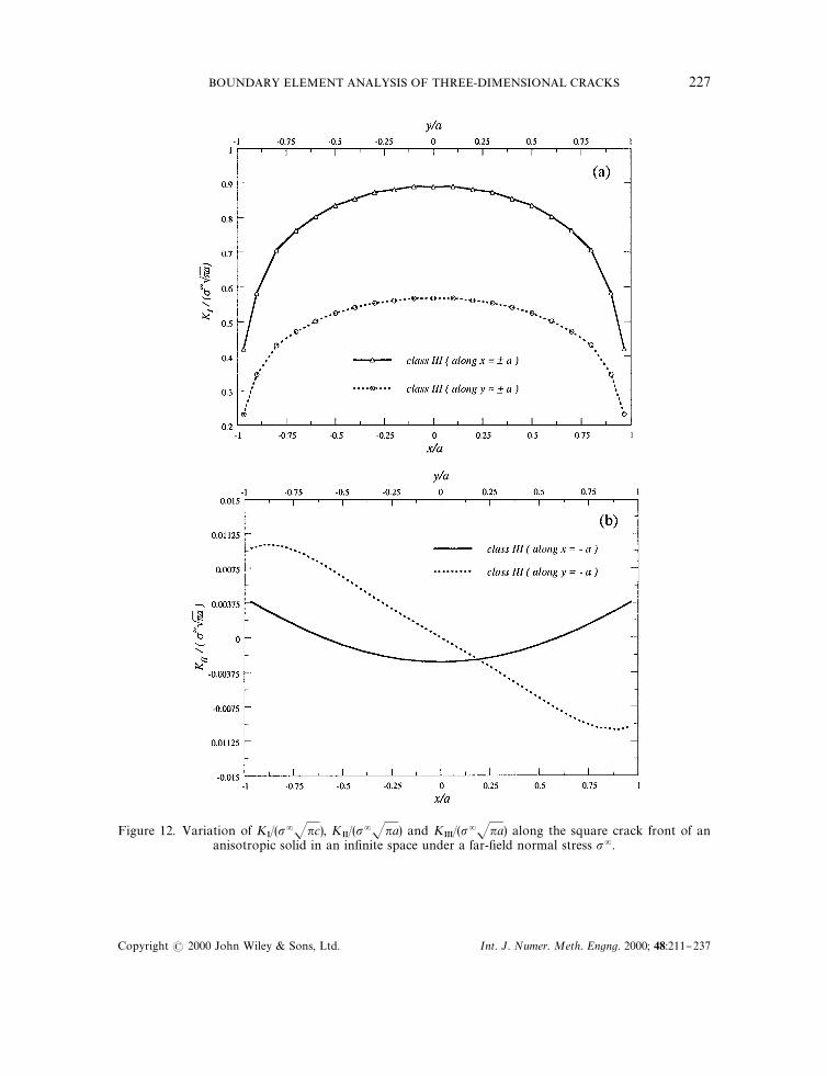
Figure 12. Variation of KI/(p=Jnc), K
II/(p=Jna) and K
III/(p=Jna) along the square crack front of an
anisotropic solid in an in"nite space under a far-"eld normal stress p=.
BOUNDARY ELEMENT ANALYSIS OF THREE-DIMENSIONAL CRACKS 227
Copyright ( 2000 John Wiley & Sons, Ltd. Int. J. Numer. Meth. Engng. 2000; 48:211}237

Figure 12. Continued.
Example 3: A square-shaped crack in a ,nite cube
To study the e!ect of "nite geometry on the SIFs, a square-shaped crack in a "nite cube undera uniform tensile stress p= applied at the top and bottom faces in the z-direction (Figure 13) isstudied. The cube has a height 2H and a width=. The side length of the square crack is 2a. In thenumerical example, the geometry is such that 2a/="0.5, H/="1, and the material is assumedto be isotropic with E"4 Msi and l"0.3. Twenty-four and 36 elements are used to discretize,respectively, the uncracked boundary and the crack surface. It is noted that, while forExamples 1 and 2, only Equation (4), with the uncracked boundary integral being discarded isneeded. For this example, however, both Equations (3) and (4) are required to model the problem.The normalized mode-I SIF along the y-axis is shown in Figure 14 and compared with that in thecorresponding in"nite medium. As expected, the normalized SIF value is larger in a "nite cubethan that in an in"nite domain, with a maximum di!erence of 6.8 per cent occurring at the middleof the square side for the chosen geometry and material property. Also in the middle of the squareside, the normalized SIF in the "nite cube is 0.8183, as compared to about 0.81 from a paper byWen and Aliabadi [40] for the same geometry.
CONCLUSIONS
A single-domain three-dimensional BEM formulation has been proposed for fracture mechanicsanalysis in anisotropic elastic cracked media. The formulation consists of a pair of integral
228 E. PAN AND F. G. YUAN
Copyright ( 2000 John Wiley & Sons, Ltd. Int. J. Numer. Meth. Engng. 2000; 48:211}237

Figure 13. Geometry of a "nite cube with a central square-shaped crack under a uniform normal stress p=.
equations, namely, the displacement and traction integral equations. While the Cauchy-typesingularity was calculated directly by the rigid-body motion method, the "nite-part integral wasevaluated by Kutt's numerical quadrature. Special crack-front elements have been introduced tocapture the crack-tip behaviour of the crack opening displacement, and an extrapolation methodof the COD is employed for the calculation of the stress intensity factors.
Numerical examples of the calculation of the SIFs for a penny-shaped and a square-shapedcrack in transversely isotropic, orthotropic and anisotropic solids were conducted. Thee!ects of material anisotropy, material orientation, crack geometry and "nite geometry on theSIFs have been demonstrated. The SIF values are in very good agreement with previouslypublished results. Material anisotropy can have a signi"cant e!ect on the SIFs. It is the authors'belief that the single-domain BEM formulation presented in this paper can be a powerfulnumerical tool, which can apply to various complex three-dimensional geometries of com-posite structures with cracks or damage under mixed-mode loading. Some of the relatedproblems are currently under investigation by the authors and results will be published ina separate paper.
APPENDIX A: GREEN'S FUNCTIONS IN TRANSVERSELY ISOTROPIC SOLIDS
In this appendix, the Green's functions in a transversely isotropic solid with any orientedisotropic plane are presented based on the results of Pan and Chou [35] and Pan and Amadei[28].
BOUNDARY ELEMENT ANALYSIS OF THREE-DIMENSIONAL CRACKS 229
Copyright ( 2000 John Wiley & Sons, Ltd. Int. J. Numer. Meth. Engng. 2000; 48:211}237
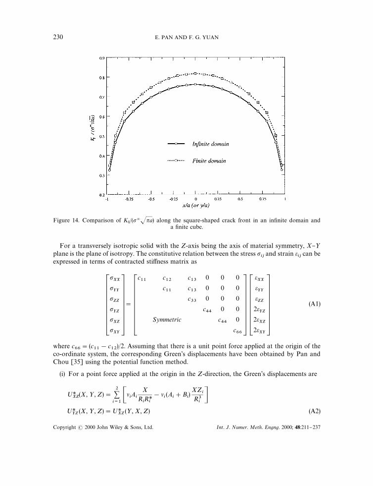
Figure 14. Comparison of KI/(p=Jna) along the square-shaped crack front in an in"nite domain and
a "nite cube.
For a transversely isotropic solid with the Z-axis being the axis of material symmetry, X}>plane is the plane of isotropy. The constitutive relation between the stress p
ijand strain e
ijcan be
expressed in terms of contracted sti!ness matrix as
pXX
pYY
pZZ
pYZ
pXZ
pXY
"
c11
c12
c13
0 0 0
c11
c13
0 0 0
c33
0 0 0
c44
0 0
Symmetric c44
0
c66
eXXeYY
eZZ
2eYZ
2eXZ
2eXY
(A1)
where c66"(c
11!c
12)/2. Assuming that there is a unit point force applied at the origin of the
co-ordinate system, the corresponding Green's displacements have been obtained by Pan andChou [35] using the potential function method.
(i) For a point force applied at the origin in the Z-direction, the Green's displacements are
;*XZ
(X, >, Z)"2+i/1CliAi
X
RiR*
i
!li(A
i#B
i)XZ
iR3
iD
;*YZ
(X, >, Z)";*XZ
(>, X, Z) (A2)
230 E. PAN AND F. G. YUAN
Copyright ( 2000 John Wiley & Sons, Ltd. Int. J. Numer. Meth. Engng. 2000; 48:211}237
;*ZZ
(X, >, Z)"!
2+i/1CA
c11
Bi#c
44l2iA
ic13#c
44B
1
Ri
#
(Ai#B
i)l2
ic13#c
44
c44
(X2#>2)#c11
Z2
R3i
D (A2)
where ;*ij(X, >, Z) is the Green's function for displacement in the i-direction at the "eld point
(X, >, Z) caused by a point force in the j-direction applied at the origin (0, 0, 0), i.e. the sourcepoint. In Equation (A2)
R*i"R
i#Z
i
Ri"JX2#>2#Z2
i(A3)
Zi"l
iZ
and the constants Aiand B
iare determined as
l1A
1"!l
2A
2"
c13#c
444nc
33c44
(l22!l2
1)
if Jc11
c33!c
13!2c
44O0 (A4)
Bi"!A
i
A1"A
2"0
B1"B
2"!
c13#c
4416nc
11c44
, if Jc11
c33!c
13!2c
44"0 (A5)
In Equations (A2)}(A5), the parameters liare related to the elastic constants c
ijas
l3"Jc
66/c
44
l1"Ja#Jb (A6)
l2"Ja!Jb
with
a"(Jc
11c33!c
13) (Jc
11c33
#c13#2c
44)
4c33
c44
b"(Jc
11c33#c
13) (Jc
11c33
!c13!2c
44)
4c33
c44
(A7)
(ii) For a point force applied at the origin in the X-direction, the Green's function fordisplacements are
;*XX
(X, >, Z)"2+i/1C(A@
i!B@
i)A
li
Ri
!
liX2
R3iB#2l
iB@iA
1
R*i
!
X2
RiR*2
iBD#DA
1
R*3
!
>2
R3R*2
3B
;*YX
(X, >, Z)"!
2+i/1Cli (A@
i!B@
i)X>
R3i
#2liB@
i
X>
RiR*2
iD#D
X>
R3R*2
3
(A8)
;*ZX
(X, >, Z)"!
2+i/1Cl2i ki (A@
i!B@
i)XZ
iR3
i
#
c11
A@i!c
44l2iB@i
c13#c
44
2X
R3R*
3D
BOUNDARY ELEMENT ANALYSIS OF THREE-DIMENSIONAL CRACKS 231
Copyright ( 2000 John Wiley & Sons, Ltd. Int. J. Numer. Meth. Engng. 2000; 48:211}237

where
ki"
c11
/l2i!c
44c13#c
44 (A9)
D"
1
4nc44
l3
and A@iand B@
iare obtained as
A@1"B@
1"!
c44!c
33l21
8nc33
c44
(l21!l2
2)l2
1
A@2"B@
2"
c44
!c33
l22
8nc33
c44
(l21!l2
2)l2
2
if Jc11
c33!c
13!2c
44O 0 (A10)
A@1"A@
2"
1
16nc11
B@1"B@
2"
1
16nc44
l21
if Jc11
c33!c
13!2c
44"0 (A11)
(iii) For a point force applied at the origin in the >-direction, the Greens function fordisplacement can be obtained by interchanging X and > in equation (A9), i.e.
;*XY
(X, >, Z)";*YX
(>, X, Z)
;*YY
(X, >, Z)";*XX
(>, X, Z) (A12)
;*ZY
(X, >, Z)";*ZX
(>, X, Z)
With these Green's functions being known exactly, their derivatives with respect to eithera source or "eld point can be directly carried out. For Green's functions in an in"nite space, as forthe current case here, their derivatives with respect to a source point are opposite to those withrespect to the corresponding "eld point.
It is observed clearly from the de"nition of R*i
(i.e. Equation (A3)) that for "eld points (X, >, Z)located on the negative Z-axis, the above Green's functions breakdown. In such a case, Green'sfunctions at the image point are calculated and imaged back to those corresponding to the "eldpoint on the negative Z-axis.
The above Green's functions are valid only in a principal material co-ordinate with the Z-axisbeing the axis of elastic symmetry. For an in"nite solid of transverse isotropy with arbitrarilyoriented isotropic plane, the Green's functions expressed in terms of the local co-ordinates(X,>,Z) need to be transformed to the global co-ordinates (x, y, z). The relationship of the global(x, y, z) and local (X,>,Z) co-ordinate systems is illustrated in Figure 6, i.e.
Cx
y
z D"H CX
>
Z D (A13)
232 E. PAN AND F. G. YUAN
Copyright ( 2000 John Wiley & Sons, Ltd. Int. J. Numer. Meth. Engng. 2000; 48:211}237
where the elements of matrix H are
H"C!cost cosb sinb sint cosb
!cost sinb !cosb sint sinb
sint 0 cost D (A14)
With the co-ordinate transformation matrix H, the Green's functions for displacements, ;*ij, in
terms of global co-ordinates can be obtained as
U*'-0"!-
"HU*-0#!-
HT (A15)
The Green's functions for tractions, ¹*ij, can be derived in a similar procedure.
APPENDIX B: GREEN'S FUNCTIONS IN ANISOTROPIC SOLIDS
The Green's functions in an anisotropic in"nite space have been derived recently by Tonon et al.[36] based on the theory of the residues. Here we outline only the displacements Green'sfunctions. Assuming that there is a unit point force applied at the origin in the j-direction, theGreen's function for displacement in the i-direction at the "eld point x can be expressed in termsof the following integral:
;*ij(x)"
1
8n2 P)!~1
ij(n)d (n )x) d) (n) (B1)
where ) is any closed surface in a three-dimensional n-space which encloses the origin pointn"0. D (x) is the delta function, and
!~1ij
(n)"(cikjl
nknl)~1 (B2)
with cikjl
being the sti!ness tensor of the anisotropic solid. It was shown in Tonon et al. [36] thatEquation (B1) can be reduced to an one-dimensional in"nite integral with the latter integral beingevaluated by the theory of the residues. Therefore, the Green's functions for displacement (B1) canbe obtained as
;*ij(x)"!
1
2nrIm C 3
+m/1
Aij(p#f
mq)
a7(f
m!fM
m)
3<k/1kOm
(fm!f
k) (f
m!fM
k)D (B3)
where the overbar denotes the complex conjugate,
Aij(n)"adj [c
ikjlnknl] , D (n)"det [c
ikjlnknl] (B4)
BOUNDARY ELEMENT ANALYSIS OF THREE-DIMENSIONAL CRACKS 233
Copyright ( 2000 John Wiley & Sons, Ltd. Int. J. Numer. Meth. Engng. 2000; 48:211}237

p and q are two vectors related to the "eld points, and akare the coe$cients of the sixth-order
polynomial D(n), i.e.
D(p#fq)"6+k/0
ak`1
fk"a7
3<m/1
(f!fm) (f!fM
m) (B5)
The three roots fm(m"1, 2, 3) are chosen with Im f
m'0. Expressions for the traction Green's
functions and their derivatives are much complicated, and they can be obtained by the e$cientand accurate numerical method proposed in Tonon et al. [36].
APPENDIX C: SHAPE FUNCTIONS FOR UNCRACKED BOUNDARY
Shape functions for type I element on the uncracked boundary
/1"0.25mg (m!1) (g!1)
/2"0.5g (1!m2) (g!1)
/3"0.25mg (m#1) (g!1)
/4"0.5m (1!g2) (m!1)
/5"(1!m2) (1!g2) (C1)
/6"0.5m (1!g2) (m#1)
/7"0.25mg (m!1) (g#1)
/8"0.5g (1!m2) (g#1)
/9"0.25mg (m#1) (g#1)
Shape functions for type II element on the uncracked boundary
/1"0.45mg(m!1) (g!1)
/2"0.9g(1!m2) (g!1)
/3"0.45mg(m#1) (g!1)
/4"0.75m(1!g) (2/3#g) (m!1)
/5"1.5(m2!1) (g!1) (2/3#g) (C2)
/6"0.75m(1!g) (2/3#g) (m#1)
/7"0.3mg(m!1) (2/3#g)
/8"0.6g(1!m2) (2/3#g)
/9"0.3mg(m#1) (2/3#g)
234 E. PAN AND F. G. YUAN
Copyright ( 2000 John Wiley & Sons, Ltd. Int. J. Numer. Meth. Engng. 2000; 48:211}237

Shape functions for type III element on the uncracked boundary
/1"0.81mg(m!1) (g!1)
/2"1.35g(1!m) (2/3#m) (g!1)
/3"0.54mg(2/3#m) (g!1)
/4"1.35m(1!g) (2/3#g) (m!1)
/5"2.25(1!m) (2/3#m) (1!g) (2/3#g) (C3)
/6"0.9m(1!g) (2/3#g) (2/3#m)
/7"0.54mg(m!1) (2/3#g)
/8"0.9g(2/3#g) (1!m) (2/3#m)
/9"0.36mg(2/3#m) (2/3#g)
Shape functions for type IV element on the uncracked boundary
/1"0.54mg(m!2/3) (g!1)
/2"!1.35g(1#m) (m!2/3) (g!1)
/3"0.81mg(m#1) (g!1)
/4"0.9m(1!g) (2/3#g) (m!2/3)
/5"!2.25(1#m) (m!2/3) (1!g) (2/3#g) (C4)
/6"1.35m(1!g) (2/3#g) (m#1)
/7"0.36mg(m!2/3) (2/3#g)
/8"!0.9g(2/3#g) (1#m) (m!2/3)
/9"0.54mg(m#1) (2/3#g)
ACKNOWLEDGEMENTS
The work presented in this paper was supported by National Science Foundation under Grant CMS-9713559, Air Force O$ce of Scienti"c Research under Grant F33615-97-C-5089 and F49620-98-1-0104.
REFERENCES
1. Cruse TA. Boundary Element Analysis in Computational Fracture Mechanics. Kluwer Academic Publishers:Dordrecht, The Netherlands, 1988.
2. Aliabadi MH. Boundary element formulations in fracture mechanics. Applied Mechanics Review 1997; 50:83}96.3. Pan E. A general boundary element analysis of 2-D linear elastic fracture mechanics. International Journal of Fracture
1997; 88:41}59.4. Snyder MD, Cruse TA. Boundary-integral analysis of anisotropic cracked plates. International Journal of Fracture
1975; 11:315}328.
BOUNDARY ELEMENT ANALYSIS OF THREE-DIMENSIONAL CRACKS 235
Copyright ( 2000 John Wiley & Sons, Ltd. Int. J. Numer. Meth. Engng. 2000; 48:211}237

5. Blandford GE, Ingra!ea AR, Liggett JA. Two-dimensional stress intensity factor computations using the boundaryelement method. International Journal for Numerical Methods in Engineering 1981; 17:387}404
6. Crouch SL, Star"eld AM. Boundary Element Methods in Solid Mechanics. George Allen and Unwin Publishers:London, 1983.
7. Pan E. Dislocation in an in"nite poroelastic medium. Acta Mechanica 1991; 87:105}115.8. Sirtori S, Maier G, Novati G, Miccoli S. A Galerkin symmetric boundary-element method in elasticity: Formulation
and implementation. International Journal for Numerical Methods in Engineering 1992; 35:255}282.9. Portela A, Aliabadi MH, Rooke DP. Dual boundary element method: E$cient implementation for cracked problems.
International Journal for Numerical Methods in Engineering 1992; 33:1269}1287.10. Mi Y, Aliabadi MH. Dual boundary element method for three-dimensional fracture mechanics analysis. Engineering
Analysis with Boundary Elements 1992; 10:161}171.11. Pan E, Amadei B. Fracture mechanics analysis of cracked 2-D anisotropic media with a new formulation of the
boundary element method. International Journal of Fracture 1996; 77:161}174.12. Qin TY, Chen WJ, Tang RJ. Three-dimensional crack problem analysis using boundary element method with"nite-part integrals. International Journal of Fracture 1997; 84:191}202.
13. Sohn GH, Hong CS. Application of singular integral equations to embedded planar crack problems in "nite body.In Brebbia AC, Maier G (eds). Boundary Element, Vol. 2, Springer: Berlin, 1985; 8-57}8-67.
14. Wong GK, Barnett DM. A dislocation method for solving 3-D crack and inclusion problems in linear elastic solids.In Bilby AB (ed.). Fundamentals of Deformation and Fracture, Eshelly Memorial Symposium, Cambridge UniversityPress: Cambridge, 1985; 417}437.
15. Gray LJ, Martha LF, Ingra!ea AR. Hypersingular integrals in boundary element fracture analysis. InternationalJournal for Numerical Methods in Engineering 1990; 29:1135}1158.
16. Martha LF, Gray LJ, Ingra!ea AR. Three-dimensional fracture simulation with a single-domain direct boundaryelement formulation. International Journal for Numerical Methods in Engineering 1992; 35:1907}1921.
17. Qin TY, Tang RJ. Finite-part integral and boundary element method to solve embedded planar crack problems.International Journal of Fracture 1993; 60:373}381.
18. Zhao M, Liu Y, Cheng C. Boundary-integral equations and the boundary-element method for three-dimensionalfracture mechanics. Engineering Analysis with Boundary Elements 1994; 13:333}338.
19. Xu Y, Moran B, Belytschko T. Self-similar crack expansion method for three-dimensional crack analysis. ASME,Journal of Applied Mechanics 1997; 64:729}737.
20. Xu Y, Moran B, Belytschko T. Self-similar crack expansion method for three-dimensional cracks under mixed-modeloading conditions. ASME, Journal of Applied Mechanics 1998; 65:557}565.
21. Sladek V, Sladek J. Three-dimensional crack analysis for an anisotropic body. Applied Mathematical Modelling 1982;6:374}381.
22. Kassir MK, Sih GC. Three-dimensional stresses around elliptical cracks in transversely isotropic solids. EngineeringFracture Mechanics 1968; 1:327}345.
23. Hoenig A. The behavior of a #at elliptical crack in an anisotropic elastic body. International Journal of Solids andStructures 1978; 14:925}934.
24. Zhang ZG, Mai YW. A simple solution for the stress intensity factor of a #at elliptical crack in a transversely isotropicsolid. Engineering Fracture Mechanics 1989; 34:645}648.
25. Ishikawa H. Application of the boundary element method to anisotropic crack problems. In Aliabadi MH,Brebbia CA (eds). Advances in Boundary Element Methods for Fracture Mechanics, Computational MechanicsPublications: Southampton, UK, 1993; 269}291.
26. Kutt HR. Quadrature formulae for "nite-part integrals. Special Report=ISK 178, National Research Institute forMathematical Sciences, Pretoria, 1975.
27. Kutt HR. On the numerical evaluation of "nite-part integrals involving an algebraic singularity. Special Report=ISK 179, National Research Institute for Mathematical Sciences, Pretoria, 1975.
28. Pan E, Amadei B. A 3-D boundary element formulation of anisotropic elasticity with gravity. Applied MathematicalModelling 1996; 20:114}120.
29. Lin W, Keer LM. Three-dimensional analysis of cracks in layered transversely isotropic media. Proceedings of RoyalSociety (¸ondon) 1989; A424:307}322.
30. Brebbia CA, Dominguez J. Boundary Element Methods, An Introductory Course. McGraw-Hill: New York, 1989.31. Ting TCT. Anisotropic Elasticity: ¹heory and Applications. Oxford University Press: Oxford, 1996.32. Sih GC, Paris PC, Irwin GR. On cracks in rectilinearly anisotropic bodies. International Journal of Fracture 1965;
3:189}203.33. Hoenig A. Near-tip behavior of a crack in a plane anisotropic elastic body. Engineering Fracture Mechanics. 1982;
16:393}403.34. Suo Z. Singularities, interfaces and cracks in dissimilar anisotropic media. Proceedings of the Royal Society (¸ondon),
1990; A427:331}358.35. Pan YC, Chou TW. Point force solution for an in"nite transversely isotropic solid. ASME Journal of Applied
Mechanics 1976; 43:608}612.
236 E. PAN AND F. G. YUAN
Copyright ( 2000 John Wiley & Sons, Ltd. Int. J. Numer. Meth. Engng. 2000; 48:211}237

36. Tonon F, Pan E, Amadei B. Green's functions and BEM formulation for 3D anisotropic media. Computers andStructures 1999; submitted.
37. Tada H, Paris PC, Irwin GR. ¹he Stress Analysis of Cracks Handbook (2nd edn). Paris Productions Incorporated:Missouri, 1985.
38. Weaver J. Three-dimensional crack analysis. International Journal of Solids and Structures. 1997; 13: 321}330.39. Murakami Y. Stress Intensity Factors Handbook. Pergamon Press: Oxford, 1987.40. Wen PH, Aliabadi MH. Mixed-mode weight functions in three-dimensional fracture mechanics: static. Engineering
Fracture Mechanics 1998; 59:563}575.
BOUNDARY ELEMENT ANALYSIS OF THREE-DIMENSIONAL CRACKS 237
Copyright ( 2000 John Wiley & Sons, Ltd. Int. J. Numer. Meth. Engng. 2000; 48:211}237


